EP3741520A1 - Robotic device and gripping method - Google Patents
Robotic device and gripping method Download PDFInfo
- Publication number
- EP3741520A1 EP3741520A1 EP20176017.0A EP20176017A EP3741520A1 EP 3741520 A1 EP3741520 A1 EP 3741520A1 EP 20176017 A EP20176017 A EP 20176017A EP 3741520 A1 EP3741520 A1 EP 3741520A1
- Authority
- EP
- European Patent Office
- Prior art keywords
- gripping
- pressure distribution
- workpiece
- posture control
- rotation
- Prior art date
- Legal status (The legal status is an assumption and is not a legal conclusion. Google has not performed a legal analysis and makes no representation as to the accuracy of the status listed.)
- Withdrawn
Links
Images



Classifications
-
- B—PERFORMING OPERATIONS; TRANSPORTING
- B25—HAND TOOLS; PORTABLE POWER-DRIVEN TOOLS; MANIPULATORS
- B25J—MANIPULATORS; CHAMBERS PROVIDED WITH MANIPULATION DEVICES
- B25J9/00—Program-controlled manipulators
- B25J9/16—Program controls
- B25J9/1694—Program controls characterised by use of sensors other than normal servo-feedback from position, speed or acceleration sensors, perception control, multi-sensor controlled systems, sensor fusion
-
- B—PERFORMING OPERATIONS; TRANSPORTING
- B25—HAND TOOLS; PORTABLE POWER-DRIVEN TOOLS; MANIPULATORS
- B25J—MANIPULATORS; CHAMBERS PROVIDED WITH MANIPULATION DEVICES
- B25J9/00—Program-controlled manipulators
- B25J9/16—Program controls
- B25J9/1612—Program controls characterised by the hand, wrist, grip control
-
- B—PERFORMING OPERATIONS; TRANSPORTING
- B25—HAND TOOLS; PORTABLE POWER-DRIVEN TOOLS; MANIPULATORS
- B25J—MANIPULATORS; CHAMBERS PROVIDED WITH MANIPULATION DEVICES
- B25J13/00—Controls for manipulators
- B25J13/08—Controls for manipulators by means of sensing devices, e.g. viewing or touching devices
- B25J13/081—Touching devices, e.g. pressure-sensitive
-
- B—PERFORMING OPERATIONS; TRANSPORTING
- B25—HAND TOOLS; PORTABLE POWER-DRIVEN TOOLS; MANIPULATORS
- B25J—MANIPULATORS; CHAMBERS PROVIDED WITH MANIPULATION DEVICES
- B25J13/00—Controls for manipulators
- B25J13/08—Controls for manipulators by means of sensing devices, e.g. viewing or touching devices
- B25J13/085—Force or torque sensors
-
- B—PERFORMING OPERATIONS; TRANSPORTING
- B25—HAND TOOLS; PORTABLE POWER-DRIVEN TOOLS; MANIPULATORS
- B25J—MANIPULATORS; CHAMBERS PROVIDED WITH MANIPULATION DEVICES
- B25J9/00—Program-controlled manipulators
-
- B—PERFORMING OPERATIONS; TRANSPORTING
- B25—HAND TOOLS; PORTABLE POWER-DRIVEN TOOLS; MANIPULATORS
- B25J—MANIPULATORS; CHAMBERS PROVIDED WITH MANIPULATION DEVICES
- B25J9/00—Program-controlled manipulators
- B25J9/16—Program controls
- B25J9/1602—Program controls characterised by the control system, structure, architecture
-
- B—PERFORMING OPERATIONS; TRANSPORTING
- B25—HAND TOOLS; PORTABLE POWER-DRIVEN TOOLS; MANIPULATORS
- B25J—MANIPULATORS; CHAMBERS PROVIDED WITH MANIPULATION DEVICES
- B25J9/00—Program-controlled manipulators
- B25J9/16—Program controls
- B25J9/1628—Program controls characterised by the control loop
- B25J9/163—Program controls characterised by the control loop learning, adaptive, model based, rule based expert control
-
- B—PERFORMING OPERATIONS; TRANSPORTING
- B25—HAND TOOLS; PORTABLE POWER-DRIVEN TOOLS; MANIPULATORS
- B25J—MANIPULATORS; CHAMBERS PROVIDED WITH MANIPULATION DEVICES
- B25J9/00—Program-controlled manipulators
- B25J9/16—Program controls
- B25J9/1656—Program controls characterised by programming, planning systems for manipulators
- B25J9/1669—Program controls characterised by programming, planning systems for manipulators characterised by special application, e.g. multi-arm co-operation, assembly, grasping
-
- G—PHYSICS
- G05—CONTROLLING; REGULATING
- G05B—CONTROL OR REGULATING SYSTEMS IN GENERAL; FUNCTIONAL ELEMENTS OF SUCH SYSTEMS; MONITORING OR TESTING ARRANGEMENTS FOR SUCH SYSTEMS OR ELEMENTS
- G05B2219/00—Program-control systems
- G05B2219/30—Nc systems
- G05B2219/39—Robotics, robotics to robotics hand
- G05B2219/39487—Parallel jaws, two fingered hand
-
- G—PHYSICS
- G05—CONTROLLING; REGULATING
- G05B—CONTROL OR REGULATING SYSTEMS IN GENERAL; FUNCTIONAL ELEMENTS OF SUCH SYSTEMS; MONITORING OR TESTING ARRANGEMENTS FOR SUCH SYSTEMS OR ELEMENTS
- G05B2219/00—Program-control systems
- G05B2219/30—Nc systems
- G05B2219/39—Robotics, robotics to robotics hand
- G05B2219/39507—Control of slip motion
-
- G—PHYSICS
- G05—CONTROLLING; REGULATING
- G05B—CONTROL OR REGULATING SYSTEMS IN GENERAL; FUNCTIONAL ELEMENTS OF SUCH SYSTEMS; MONITORING OR TESTING ARRANGEMENTS FOR SUCH SYSTEMS OR ELEMENTS
- G05B2219/00—Program-control systems
- G05B2219/30—Nc systems
- G05B2219/39—Robotics, robotics to robotics hand
- G05B2219/39508—Reorientation of object, orient, regrasp object
-
- G—PHYSICS
- G05—CONTROLLING; REGULATING
- G05B—CONTROL OR REGULATING SYSTEMS IN GENERAL; FUNCTIONAL ELEMENTS OF SUCH SYSTEMS; MONITORING OR TESTING ARRANGEMENTS FOR SUCH SYSTEMS OR ELEMENTS
- G05B2219/00—Program-control systems
- G05B2219/30—Nc systems
- G05B2219/39—Robotics, robotics to robotics hand
- G05B2219/39509—Gripping, grasping, links embrace, encircle, envelop object to grasp
-
- G—PHYSICS
- G05—CONTROLLING; REGULATING
- G05B—CONTROL OR REGULATING SYSTEMS IN GENERAL; FUNCTIONAL ELEMENTS OF SUCH SYSTEMS; MONITORING OR TESTING ARRANGEMENTS FOR SUCH SYSTEMS OR ELEMENTS
- G05B2219/00—Program-control systems
- G05B2219/30—Nc systems
- G05B2219/39—Robotics, robotics to robotics hand
- G05B2219/39514—Stability of grasped objects
Definitions
- the present disclosure relates to a robotic device and a gripping method.
- a robotic device When gripping and transporting a workpiece with a robotic device, the gripped workpiece may slip and fall due to the weight, shape, or surface state of the workpiece. Therefore, a robotic device is provided which increases gripping power to further prevent slippage when detecting slippage in the gripped workpiece.
- a robotic device includes an end effector device, a first sensor, and a controller.
- the end effector device includes two fingers for gripping a workpiece.
- the first sensor detects a pressure distribution on a gripping position on the workpiece by the two fingers.
- the controller performs, based on a temporal variation in the pressure distribution when the workpiece is lifted, posture control including rotation of the end effector device.
- a gripping method is for gripping a workpiece using a robotic device including an end effector device and a first sensor.
- the end effector device includes two fingers.
- the first sensor is for detecting a pressure distribution on a gripping position of the workpiece by the two fingers.
- the gripping method includes: gripping the workpiece using the two fingers; detecting a pressure distribution on a gripping position on the workpiece; and performing, based on a temporal variation of the pressure distribution when the workpiece is lifted, posture control including rotation of the end effector device.
- FIGS. 1 to 4 An embodiment of the present disclosure will hereinafter be described with reference to FIGS. 1 to 4 . Elements that are the same or equivalent are labelled with the same reference signs in the drawings and description thereof is not repeated.
- FIG. 1 is a perspective view of an appearance example of the robotic device 10.
- directions intersecting each other on a horizontal plane are a positive X axial direction and a positive Y axial direction, and upward in a vertical direction is a positive Z axial direction.
- the robotic device 10 includes a base 20, a robotic hand device 26, and an end effector device 30.
- the robotic hand device 26 is mounted on the base 20.
- the end effector device 30 is replaceable and connected to a distal end of the robotic hand device 26.
- the robotic hand device 26 drives the end effector device 30.
- end effector may hereinafter also be referred to as "EE”.
- the robotic hand device 26 includes a plurality of arms coupled to each other. Specifically, the robotic hand device 26 includes a shoulder 21, a lower arm 22, a first upper arm 23, a second upper arm 24, and a wrist 25.
- the shoulder 21 is coupled to the base 20 and allowed to pivot around a first axis L1 extending in a Z axial direction.
- the lower arm 22 is coupled to the shoulder 21 and allowed to pivot around a second axis L2 extending in a direction intersecting the first axis L1 to move up and down.
- the first upper arm 23 is coupled to a distal end of the lower arm 22 and allowed to pivot around a third axis L3 extending parallel to the second axis L2 to move up and down.
- the second upper arm 24 is coupled to a distal end of the first upper arm 23 and allowed to twist and turn around a fourth axis L4 extending parallel to the third axis L3.
- the wrist 25 is coupled to a distal end of the second upper arm 24 and allowed to pivot around a fifth axis L5 extending in a direction intersecting the fourth axis L4 to move up and down.
- the EE device 30 is configured as a gripping mechanism that includes a housing 31, a first finger 32, and a second finger 33.
- the housing 31 is connected to a distal end of the wrist 25 and allowed to twist and turn around a sixth axis L6 extending in a direction intersecting the fifth axis L5.
- the first finger 32 and the second finger 33 protrude from an opening provided in the housing 31 so as to grip a workpiece.
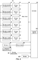
- FIG. 2 is a block diagram illustrating an example of the circuit configuration of the robotic device 10.
- the robotic device 10 includes a motor driver 50, a first axis motor 51, a second axis motor 52, a third axis motor 53, a fourth axis motor 54, a fifth axis motor 55, and a sixth axis motor 56.
- the motor driver 50 drives the first to sixth axis motors 51 to 56.
- the first axis motor 51 rotates the shoulder 21 around the first axis L1.
- the second axis motor 52 rotates the lower arm 22 around the second axis L2.
- the third axis motor 53 rotates the first upper arm 23 around the third axis L3.
- the fourth axis motor 54 rotates the second upper arm 24 around the fourth axis L4.
- the fifth axis motor 55 rotates the wrist 25 around the fifth axis L5.
- the sixth axis motor 56 rotates the EE device 30 around the sixth axis L6.
- the robotic device 10 also includes a first axis encoder and torque sensor 61, a second axis encoder and torque sensor 62, and a third axis encoder and torque sensor 63.
- the robotic device 10 further includes a fourth axis encoder and torque sensor 64, a fifth axis encoder and torque sensor 65, and a sixth axis encoder and torque sensor 66.
- the first axis encoder and torque sensor 61 detects a rotational position and torque of the first axis motor 51 and outputs a first encoder signal and a first torque signal.
- the second axis encoder and torque sensor 62 detects a rotational position and torque of the second axis motor 52 and outputs a second encoder signal and a second torque signal.
- the third axis encoder and torque sensor 63 detects a rotational position and torque of the third axis motor 53 and outputs a third encoder signal and a third torque signal.
- the fourth axis encoder and torque sensor 64 detects a rotational position and torque of the fourth axis motor 54 and outputs a fourth encoder signal and a fourth torque signal.
- the fifth axis encoder and torque sensor 65 detects a rotational position and torque of the fifth axis motor 55 and outputs a fifth encoder signal and a fifth torque signal.
- the sixth axis encoder and torque sensor 66 detects a rotational position and torque of the sixth axis motor 56 and outputs a sixth encoder signal and a sixth torque signal.
- the robotic device 10 further includes a pressure distribution sensor 40, a gripping torque sensor 45, an effector driver 80, a controller 90, and storage 100.
- the controller 90 provides a control signal to the motor driver 50 to perform posture control of the robotic hand device 26.
- the first to sixth encoder signals which indicate the posture of the robotic hand device 26 are fed back to the controller 90.
- the first to sixth torque signals are also fed back to the controller 90.
- the effector driver 80 drives the first finger 32 and the second finger 33.
- the controller 90 provides a control signal to the effector driver 80 to move the first finger 32 and the second finger 33.
- the pressure distribution sensor 40 and the gripping torque sensor 45 are embedded in the EE device 30.
- the pressure distribution sensor 40 detects a pressure distribution on a gripping position on the workpiece by the first finger 32 and the second finger 33. An output signal from the pressure distribution sensor 40 is supplied to the controller 90.
- the pressure distribution sensor 40 is equivalent to an example of a "first sensor".
- the gripping torque sensor 45 detects gripping torque on the workpiece.
- the gripping torque is torque of an unillustrated motor driving the first finger 32 and the second finger 33.
- the gripping torque sensor 45 is equivalent to an example of a "second sensor".
- the controller 90 includes a neural network and a processor such as a central processing unit (CPU).
- the storage 100 includes a main storage device such as semiconductor memory and an auxiliary storage device such as a hard disk drive.
- the storage 100 stores therein data and a computer program.
- the processor of the controller 90 executes the computer program stored in the storage 100, thereby controlling each component of the robotic device 10.
- the controller 90 includes a learning section 120.
- the learning section 120 performs supervised learning based on a plurality of trials including gripping of the workpiece using the first finger 32 and the second finger 33 and movement and rotation of a tool center point (TCP) of the EE device 30.
- TCP tool center point
- the learning is individually performed for each of a plurality of workpieces having mutually different shapes.
- the learning section 120 stores therein a result of the learning.
- the neural network of the controller 90 functions as the learning section 120. Note that the learning may be performed in a virtual environment.
- the controller 90 performs posture control including rotation of the EE device 30 based on temporal variation in the pressure distribution when a workpiece is lifted.
- FIG. 3 is a block diagram illustrating an example of the input to the learning section 120.
- the learning data includes (1) a pressure distribution, (2) a temporal variation in the pressure distribution, (3) a movement amount of the TCP, (4) a rotation amount of the TCP, (5) a movement speed of the TCP, and (6) a gripping torque.
- the pressure distribution is obtained from the output of the pressure distribution sensor 40.
- the gripping torque is obtained from the output of the gripping torque sensor 45.
- the label includes a movement amount of the pressure distribution, that is to say a slippage amount.
- the learning section 120 performs supervised learning. Based on the result of the supervised learning, the learning section 120 determines the movement amount and the rotation amount of the TCP such that the movement amount of the pressure distribution after posture control by the controller 90 is small.
- the learning section 120 performs additional supervised learning. Based on the result of the additional supervised learning, under a condition where the movement amount of the pressure distribution after the posture control by the controller 90 is greater than a first threshold, the learning section 120 determines the gripping torque prior to the posture control such that the gripping torque prior to the posture control is small.
- the learning section 120 additionally determines the movement speed of the TCP such that the movement speed of the TCP is high.
- the learning section 120 performs additional supervised learning. Based on the result of the additional supervised learning, under a condition where the movement amount of the pressure distribution after the posture control by the controller 90 is greater than a third threshold, the learning section 120 determines the gripping torque after the posture control such that the gripping torque after the posture control is small.
- FIG. 4 is a flowchart depicting an example of the workpiece conveyance control by the controller 90.
- the learning section 120 stores therein the result of supervised learning.
- Step S200 As illustrated in FIG. 4 , the controller 90 controls the effector driver 80 so that the EE device 30 grips the workpiece using the first finger 32 and the second finger 33.
- the pressure distribution sensor 40 detects the pressure distribution on the gripping position on the workpiece.
- Step S202 The controller 90 controls the motor driver 50 so that the robotic hand device 26 lifts the workpiece using the EE device 30.
- Step S202 in the process ends, the process of the controller 90 proceeds to Step S204.
- Step S204 The controller 90 detects the temporal variation in the pressure distribution when the workpiece is lifted.
- Step S204 in the process ends, the process of the controller 90 proceeds to Step S206.
- Step S206 The controller 90 performs posture control of the EE device 30 using the result of the supervised learning of the learning section 120. That is, the controller 90 performs posture control including rotation of the EE device 30 based on the temporal variation in the pressure distribution when the workpiece is lifted.
- Step S208 the process of the controller 90 proceeds to Step S208.
- Step S208 The controller 90 determines whether or not the movement amount of the pressure distribution after posture control of the EE device 30, that is to say the slippage amount, is equal to or less than a fourth threshold.
- the process of the controller 90 proceeds to Step S210.
- the process of the controller 90 returns to Step S200 so that gripping of the workpiece using the first finger 32 and the second finger 33 is retried.
- Step S210 The controller 90 controls the motor driver 50 to move the TCP of the EE device 30 to a desired position.
- Step S210 in the process ends, the process of the controller 90 ends.
- the embodiment provides the robotic device 10 capable of preventing a fall of the workpiece while suppressing gripping force.
- the robotic device 10 has six degrees of freedom, but the present disclosure is not limited to this.
- the robotic device 10 may have five or fewer degrees of freedom, or seven or more degrees of freedom.
Landscapes
- Engineering & Computer Science (AREA)
- Robotics (AREA)
- Mechanical Engineering (AREA)
- Human Computer Interaction (AREA)
- Health & Medical Sciences (AREA)
- General Health & Medical Sciences (AREA)
- Orthopedic Medicine & Surgery (AREA)
- Automation & Control Theory (AREA)
- Manipulator (AREA)
Abstract
Description
- The present disclosure relates to a robotic device and a gripping method.
- When gripping and transporting a workpiece with a robotic device, the gripped workpiece may slip and fall due to the weight, shape, or surface state of the workpiece. Therefore, a robotic device is provided which increases gripping power to further prevent slippage when detecting slippage in the gripped workpiece.
- A robotic device according to an aspect of the present disclosure includes an end effector device, a first sensor, and a controller. The end effector device includes two fingers for gripping a workpiece. The first sensor detects a pressure distribution on a gripping position on the workpiece by the two fingers. The controller performs, based on a temporal variation in the pressure distribution when the workpiece is lifted, posture control including rotation of the end effector device.
- A gripping method according to an aspect of the present disclosure is for gripping a workpiece using a robotic device including an end effector device and a first sensor. The end effector device includes two fingers. The first sensor is for detecting a pressure distribution on a gripping position of the workpiece by the two fingers. The gripping method includes: gripping the workpiece using the two fingers; detecting a pressure distribution on a gripping position on the workpiece; and performing, based on a temporal variation of the pressure distribution when the workpiece is lifted, posture control including rotation of the end effector device.
-
-
FIG. 1 is a perspective view of an appearance example of a robotic device according to an embodiment. -
FIG. 2 is a block diagram illustrating an example of a circuit configuration of the robotic device. -
FIG. 3 is a block diagram illustrating an example of input to a learning section. -
FIG. 4 is a flowchart depicting an example of workpiece conveyance control by a controller. - An embodiment of the present disclosure will hereinafter be described with reference to
FIGS. 1 to 4 . Elements that are the same or equivalent are labelled with the same reference signs in the drawings and description thereof is not repeated. - A
robotic device 10 according to the embodiment will first be described with reference toFIG. 1. FIG. 1 is a perspective view of an appearance example of therobotic device 10. InFIG. 1 , directions intersecting each other on a horizontal plane are a positive X axial direction and a positive Y axial direction, and upward in a vertical direction is a positive Z axial direction. - As illustrated in
FIG. 1 , therobotic device 10 includes abase 20, arobotic hand device 26, and anend effector device 30. Therobotic hand device 26 is mounted on thebase 20. Theend effector device 30 is replaceable and connected to a distal end of therobotic hand device 26. Therobotic hand device 26 drives theend effector device 30. Note that end effector may hereinafter also be referred to as "EE". - The
robotic hand device 26 includes a plurality of arms coupled to each other. Specifically, therobotic hand device 26 includes ashoulder 21, alower arm 22, a firstupper arm 23, a secondupper arm 24, and awrist 25. - The
shoulder 21 is coupled to thebase 20 and allowed to pivot around a first axis L1 extending in a Z axial direction. - The
lower arm 22 is coupled to theshoulder 21 and allowed to pivot around a second axis L2 extending in a direction intersecting the first axis L1 to move up and down. - The first
upper arm 23 is coupled to a distal end of thelower arm 22 and allowed to pivot around a third axis L3 extending parallel to the second axis L2 to move up and down. - The second
upper arm 24 is coupled to a distal end of the firstupper arm 23 and allowed to twist and turn around a fourth axis L4 extending parallel to the third axis L3. - The
wrist 25 is coupled to a distal end of the secondupper arm 24 and allowed to pivot around a fifth axis L5 extending in a direction intersecting the fourth axis L4 to move up and down. - The
EE device 30 is configured as a gripping mechanism that includes ahousing 31, afirst finger 32, and asecond finger 33. Thehousing 31 is connected to a distal end of thewrist 25 and allowed to twist and turn around a sixth axis L6 extending in a direction intersecting the fifth axis L5. Thefirst finger 32 and thesecond finger 33 protrude from an opening provided in thehousing 31 so as to grip a workpiece. - A circuit configuration of the
robotic device 10 will next be described with reference toFIGS. 1 and2. FIG. 2 is a block diagram illustrating an example of the circuit configuration of therobotic device 10. - As illustrated in
FIG. 2 , therobotic device 10 includes amotor driver 50, afirst axis motor 51, asecond axis motor 52, athird axis motor 53, afourth axis motor 54, afifth axis motor 55, and asixth axis motor 56. Themotor driver 50 drives the first tosixth axis motors 51 to 56. Thefirst axis motor 51 rotates theshoulder 21 around the first axis L1. Thesecond axis motor 52 rotates thelower arm 22 around the second axis L2. Thethird axis motor 53 rotates the firstupper arm 23 around the third axis L3. Thefourth axis motor 54 rotates the secondupper arm 24 around the fourth axis L4. Thefifth axis motor 55 rotates thewrist 25 around the fifth axis L5. Thesixth axis motor 56 rotates theEE device 30 around the sixth axis L6. - The
robotic device 10 also includes a first axis encoder andtorque sensor 61, a second axis encoder andtorque sensor 62, and a third axis encoder andtorque sensor 63. Therobotic device 10 further includes a fourth axis encoder andtorque sensor 64, a fifth axis encoder andtorque sensor 65, and a sixth axis encoder andtorque sensor 66. The first axis encoder andtorque sensor 61 detects a rotational position and torque of thefirst axis motor 51 and outputs a first encoder signal and a first torque signal. The second axis encoder andtorque sensor 62 detects a rotational position and torque of thesecond axis motor 52 and outputs a second encoder signal and a second torque signal. The third axis encoder andtorque sensor 63 detects a rotational position and torque of thethird axis motor 53 and outputs a third encoder signal and a third torque signal. The fourth axis encoder andtorque sensor 64 detects a rotational position and torque of thefourth axis motor 54 and outputs a fourth encoder signal and a fourth torque signal. The fifth axis encoder andtorque sensor 65 detects a rotational position and torque of thefifth axis motor 55 and outputs a fifth encoder signal and a fifth torque signal. The sixth axis encoder andtorque sensor 66 detects a rotational position and torque of thesixth axis motor 56 and outputs a sixth encoder signal and a sixth torque signal. - The
robotic device 10 further includes apressure distribution sensor 40, agripping torque sensor 45, aneffector driver 80, acontroller 90, andstorage 100. - The
controller 90 provides a control signal to themotor driver 50 to perform posture control of therobotic hand device 26. The first to sixth encoder signals which indicate the posture of therobotic hand device 26 are fed back to thecontroller 90. The first to sixth torque signals are also fed back to thecontroller 90. - The
effector driver 80 drives thefirst finger 32 and thesecond finger 33. Thecontroller 90 provides a control signal to theeffector driver 80 to move thefirst finger 32 and thesecond finger 33. Thepressure distribution sensor 40 and thegripping torque sensor 45 are embedded in theEE device 30. - The
pressure distribution sensor 40 detects a pressure distribution on a gripping position on the workpiece by thefirst finger 32 and thesecond finger 33. An output signal from thepressure distribution sensor 40 is supplied to thecontroller 90. Thepressure distribution sensor 40 is equivalent to an example of a "first sensor". - The gripping
torque sensor 45 detects gripping torque on the workpiece. The gripping torque is torque of an unillustrated motor driving thefirst finger 32 and thesecond finger 33. The grippingtorque sensor 45 is equivalent to an example of a "second sensor". - The
controller 90 includes a neural network and a processor such as a central processing unit (CPU). Thestorage 100 includes a main storage device such as semiconductor memory and an auxiliary storage device such as a hard disk drive. Thestorage 100 stores therein data and a computer program. The processor of thecontroller 90 executes the computer program stored in thestorage 100, thereby controlling each component of therobotic device 10. - The
controller 90 includes alearning section 120. Thelearning section 120 performs supervised learning based on a plurality of trials including gripping of the workpiece using thefirst finger 32 and thesecond finger 33 and movement and rotation of a tool center point (TCP) of theEE device 30. The learning is individually performed for each of a plurality of workpieces having mutually different shapes. Thelearning section 120 stores therein a result of the learning. The neural network of thecontroller 90 functions as thelearning section 120. Note that the learning may be performed in a virtual environment. - The
controller 90 performs posture control including rotation of theEE device 30 based on temporal variation in the pressure distribution when a workpiece is lifted. - Input to the
learning section 120 will next be described with reference toFIGS. 1 to 3 .FIG. 3 is a block diagram illustrating an example of the input to thelearning section 120. - As illustrated in
FIG. 3 , learning data and a label are provided to thelearning section 120. The learning data includes (1) a pressure distribution, (2) a temporal variation in the pressure distribution, (3) a movement amount of the TCP, (4) a rotation amount of the TCP, (5) a movement speed of the TCP, and (6) a gripping torque. The pressure distribution is obtained from the output of thepressure distribution sensor 40. The gripping torque is obtained from the output of thegripping torque sensor 45. The label includes a movement amount of the pressure distribution, that is to say a slippage amount. - Specifically, having been provided as learning data the temporal variation in the pressure distribution and the movement amount and the rotation amount of the TCP, and having been provided as a label the movement amount of the pressure distribution after rotation, the
learning section 120 performs supervised learning. Based on the result of the supervised learning, thelearning section 120 determines the movement amount and the rotation amount of the TCP such that the movement amount of the pressure distribution after posture control by thecontroller 90 is small. - Having been further provided as learning data the gripping torque prior to rotation, the
learning section 120 performs additional supervised learning. Based on the result of the additional supervised learning, under a condition where the movement amount of the pressure distribution after the posture control by thecontroller 90 is greater than a first threshold, thelearning section 120 determines the gripping torque prior to the posture control such that the gripping torque prior to the posture control is small. - Under a condition where the movement amount of the pressure distribution after posture control by the
controller 90 is greater than a second threshold, thelearning section 120 additionally determines the movement speed of the TCP such that the movement speed of the TCP is high. - Having been further provided as learning data the gripping torque after rotation and the temporal variation in the pressure distribution after rotation, the
learning section 120 performs additional supervised learning. Based on the result of the additional supervised learning, under a condition where the movement amount of the pressure distribution after the posture control by thecontroller 90 is greater than a third threshold, thelearning section 120 determines the gripping torque after the posture control such that the gripping torque after the posture control is small. - Workpiece conveyance control by the
controller 90 will next be described with reference toFIGS. 1 to 4 .FIG. 4 is a flowchart depicting an example of the workpiece conveyance control by thecontroller 90. Thelearning section 120 stores therein the result of supervised learning. - At Step S200: As illustrated in
FIG. 4 , thecontroller 90 controls theeffector driver 80 so that theEE device 30 grips the workpiece using thefirst finger 32 and thesecond finger 33. Thepressure distribution sensor 40 detects the pressure distribution on the gripping position on the workpiece. When Step S200 in the process ends, the process of thecontroller 90 proceeds to Step S202. - At Step S202: The
controller 90 controls themotor driver 50 so that therobotic hand device 26 lifts the workpiece using theEE device 30. When Step S202 in the process ends, the process of thecontroller 90 proceeds to Step S204. - At Step S204: The
controller 90 detects the temporal variation in the pressure distribution when the workpiece is lifted. When Step S204 in the process ends, the process of thecontroller 90 proceeds to Step S206. - At Step S206: The
controller 90 performs posture control of theEE device 30 using the result of the supervised learning of thelearning section 120. That is, thecontroller 90 performs posture control including rotation of theEE device 30 based on the temporal variation in the pressure distribution when the workpiece is lifted. When Step S206 in the process ends, the process of thecontroller 90 proceeds to Step S208. - At Step S208: The
controller 90 determines whether or not the movement amount of the pressure distribution after posture control of theEE device 30, that is to say the slippage amount, is equal to or less than a fourth threshold. When thecontroller 90 determines that the movement amount of the pressure distribution is equal to or less than the fourth threshold (Yes in Step S208), the process of thecontroller 90 proceeds to Step S210. When thecontroller 90 determines that the movement amount of the pressure distribution is greater than the fourth threshold (No in Step S208), the process of thecontroller 90 returns to Step S200 so that gripping of the workpiece using thefirst finger 32 and thesecond finger 33 is retried. - At Step S210: The
controller 90 controls themotor driver 50 to move the TCP of theEE device 30 to a desired position. When Step S210 in the process ends, the process of thecontroller 90 ends. - The embodiment provides the
robotic device 10 capable of preventing a fall of the workpiece while suppressing gripping force. - The embodiment of the present disclosure is described above with reference to the accompanying drawings. However, the present disclosure is not limited to the above embodiment and may be implemented in various manners within a scope not departing from the gist thereof. Furthermore, various disclosures may be created by appropriately combining elements of configuration disclosed in the above embodiment. For example, some of elements of configuration may be removed from the entirety thereof disclosed in the embodiment. The drawings illustrate main elements of configuration schematically to facilitate understanding thereof. Aspects of the elements of configuration such as number illustrated in the drawings may differ in practice for the sake of convenience for drawing preparation. Furthermore, the elements of configuration described in the above embodiment are merely examples and not particular limitations. The elements of configuration may be variously altered within a scope not substantially departing from the effects of the present disclosure.
- In the embodiment, the
robotic device 10 has six degrees of freedom, but the present disclosure is not limited to this. Therobotic device 10 may have five or fewer degrees of freedom, or seven or more degrees of freedom.
Claims (12)
- A robotic device (10) comprising:an end effector device (30) including two fingers (32, 33) for gripping a workpiece;a first sensor (40) configured to detect a pressure distribution on a gripping position on the workpiece by the two fingers; anda controller (90) configured to perform, based on a temporal variation in the pressure distribution when the workpiece is lifted, posture control including rotation of the end effector device.
- The robotic device according to claim 1, wherein
the controller includes a learning section (120) which, based on a plurality of trials including the gripping of the workpiece using the two fingers and movement and rotation of a tool center point of the end effector device, performs supervised learning having been provided as learning data the temporal variation in the pressure distribution and a movement amount and a rotation amount of the tool center point and having been provided as a label a movement amount of the pressure distribution after the rotation, and
the learning section determines, based on a result of the supervised learning, the movement amount and the rotation amount of the tool center point such that the movement amount of the pressure distribution after the posture control is small. - The robotic device according to claim 2, further comprising
a second sensor (45) configured to detect gripping torque on the workpiece, wherein
based on a result of the supervised learning having been further provided as learning data the gripping torque prior to the rotation, under a condition where the movement amount of the pressure distribution after the posture control is greater than a first threshold, the learning section determines the gripping torque prior to the posture control such that the gripping torque prior to the posture control is small. - The robotic device according to claims 2 or 3, wherein
under a condition where the movement amount of the pressure distribution after the posture control is greater than a second threshold, the learning section determines a movement speed of the tool center point such that the movement speed of the tool center point is high. - The robotic device according to claim 2, further comprising
a second sensor (45) configured to detect a gripping torque on the workpiece, wherein
based on a result of the supervised learning having been further provided as learning data the gripping torque after the rotation and the temporal variation in the pressure distribution after the rotation, under a condition where the movement amount of the pressure distribution after the posture control is greater than a third threshold, the learning section determines the gripping torque after the posture control such that the gripping torque after the posture control is small. - The robotic device according to claim 1, wherein
when a movement amount of the pressure distribution is greater than a fourth threshold when the workpiece is lifted, the controller performs control so as to retry gripping of the workpiece using the two fingers. - A gripping method for gripping a workpiece using a robotic device (10) including an end effector device (30) and a first sensor (40), the end effector device including two fingers (32, 33), the first sensor for detecting a pressure distribution on a gripping position on the workpiece by the two fingers, the gripping method comprising:gripping the workpiece using the two fingers;detecting a pressure distribution on a gripping position on the workpiece; andperforming, based on a temporal variation in the pressure distribution when the workpiece is lifted, posture control including rotation of the end effector device.
- The gripping method according to claim 7, further comprising:performing, based on a plurality of trials including the gripping of the workpiece using the two fingers and movement and rotation of a tool center point of the end effector device, supervised learning having been provided as learning data the temporal variation in the pressure distribution and a movement amount and a rotation amount of the tool center point and having been provided as a label a movement amount of the pressure distribution after the rotation; anddetermining, based on a result of the supervised learning, the movement amount and the rotation amount of the tool center point such that the movement amount of the pressure distribution after the posture control is small.
- The gripping method according to claim 8, wherein
the robotic device further includes a second sensor (45) for detecting gripping torque on the workpiece, and
the gripping method further comprises determining, based on a result of the supervised learning having been further provided as learning data the gripping torque prior to the rotation, under a condition where the movement amount of the pressure distribution after the posture control is greater than a first threshold, the gripping torque prior to the posture control such that the gripping torque prior to the posture control is small. - The gripping method according to claims 8 or 9, further comprising
determining, under a condition where the movement amount of the pressure distribution after the posture control is greater than a second threshold, a movement speed of the tool center point such that the movement speed of the tool center point is high. - The gripping method according to claim 8, wherein
the robotic device further includes a second sensor (45) for detecting gripping torque on the workpiece, and
the gripping method further comprises determining, based on a result of the supervised learning having been further provided as learning data the gripping torque after the rotation and the temporal variation in the pressure distribution after the rotation, under a condition where the movement amount of the pressure distribution after the posture control is greater than a third threshold, the gripping torque after the posture control such that the gripping torque after the posture control is small. - The gripping method according to claim 7, further comprising
retrying the gripping of the workpiece using the two fingers when a movement amount of the pressure distribution when the workpiece is lifted is greater than a fourth threshold.
Applications Claiming Priority (1)
| Application Number | Priority Date | Filing Date | Title |
|---|---|---|---|
| JP2019097769A JP2020192614A (en) | 2019-05-24 | 2019-05-24 | Robot device and gripping method |
Publications (1)
| Publication Number | Publication Date |
|---|---|
| EP3741520A1 true EP3741520A1 (en) | 2020-11-25 |
Family
ID=70804500
Family Applications (1)
| Application Number | Title | Priority Date | Filing Date |
|---|---|---|---|
| EP20176017.0A Withdrawn EP3741520A1 (en) | 2019-05-24 | 2020-05-22 | Robotic device and gripping method |
Country Status (4)
| Country | Link |
|---|---|
| US (1) | US11325248B2 (en) |
| EP (1) | EP3741520A1 (en) |
| JP (1) | JP2020192614A (en) |
| CN (1) | CN111975764B (en) |
Families Citing this family (5)
| Publication number | Priority date | Publication date | Assignee | Title |
|---|---|---|---|---|
| TW202147181A (en) * | 2020-06-10 | 2021-12-16 | 淡江大學 | Three-finger mechanical gripper system and training method thereof |
| JP7549876B2 (en) * | 2020-12-07 | 2024-09-12 | 国立研究開発法人産業技術総合研究所 | ROBOT HAND SYSTEM AND ROBOT HAND OPERATION CONTROL METHOD |
| CN114431961B (en) * | 2022-01-26 | 2023-12-26 | 上海微创医疗机器人(集团)股份有限公司 | Control method of doctor console and doctor console |
| JP2024002787A (en) * | 2022-06-24 | 2024-01-11 | セイコーエプソン株式会社 | Gripping position setting method and robot system |
| WO2024172362A1 (en) * | 2023-02-15 | 2024-08-22 | 삼성전자주식회사 | Robot hand and control method therefor |
Citations (1)
| Publication number | Priority date | Publication date | Assignee | Title |
|---|---|---|---|---|
| US20110137463A1 (en) * | 2009-12-09 | 2011-06-09 | Gm Global Technology Operations, Inc. | Systems and methods associated with handling an object with a gripper |
Family Cites Families (28)
| Publication number | Priority date | Publication date | Assignee | Title |
|---|---|---|---|---|
| US4621332A (en) * | 1983-06-20 | 1986-11-04 | Hitachi, Ltd. | Method and apparatus for controlling a robot utilizing force, position, velocity, spring constant, mass coefficient, and viscosity coefficient |
| US4860215A (en) * | 1987-04-06 | 1989-08-22 | California Institute Of Technology | Method and apparatus for adaptive force and position control of manipulators |
| US4999553A (en) * | 1989-12-28 | 1991-03-12 | The United States Of America As Represented By The Administrator Of The National Aeronautics And Space Administration | Method and apparatus for configuration control of redundant robots |
| US5631861A (en) * | 1990-02-02 | 1997-05-20 | Virtual Technologies, Inc. | Force feedback and texture simulating interface device |
| KR100191107B1 (en) * | 1990-11-06 | 1999-06-15 | 이데이 노부유끼 | Signal processing method |
| JP2793493B2 (en) * | 1993-12-28 | 1998-09-03 | 本田技研工業株式会社 | Robot hand grip control method |
| IT1306514B1 (en) * | 1998-08-05 | 2001-06-11 | Vincenzo Arrichiello | BELLOW ACTUATION DEVICE, ESPECIALLY FOR ROTARY MANIPULATOR, AND METHOD OF DRIVING THAT DEVICE. |
| WO2005000538A1 (en) * | 2003-06-27 | 2005-01-06 | Matsushita Electric Industrial Co., Ltd. | Layered-type multi-joint portion drive mechanism, method of producing the mechanism, grip hand with the mechanism, and robot arm |
| JP2005177977A (en) | 2003-11-25 | 2005-07-07 | Matsushita Electric Works Ltd | Robot hand control device |
| EP1701825A4 (en) * | 2003-12-30 | 2007-04-18 | Strider Labs Inc | Robotic hand with extendable palm |
| JP2006102920A (en) * | 2004-10-08 | 2006-04-20 | Fanuc Ltd | Grip-type hand |
| JP5187552B2 (en) * | 2007-09-13 | 2013-04-24 | ソニー株式会社 | Control device and method, program, and recording medium |
| US20130079905A1 (en) * | 2010-06-03 | 2013-03-28 | Hitachi, Ltd. | Human-Operated Working Machine System |
| JP5480340B2 (en) * | 2012-07-26 | 2014-04-23 | ファナック株式会社 | Take-out robot system using roller device |
| US9004559B2 (en) * | 2012-11-09 | 2015-04-14 | Irobot Corporation | Compliant underactuated grasper |
| CN103448061B (en) * | 2013-08-07 | 2015-08-12 | 西北农林科技大学 | A kind of kiwifruit fruit picking end effector |
| EP4019209B1 (en) * | 2015-06-26 | 2024-11-13 | Soft Robotics, Inc. | Food handling gripper |
| AU2017209289A1 (en) * | 2016-01-20 | 2018-08-09 | Soft Robotics, Inc. | Soft robotic grippers for cluttered grasping environments, high acceleration movements, food manipulation, and automated storage and retrieval systems |
| US10717187B2 (en) * | 2016-02-01 | 2020-07-21 | AM Networks LLC | Desktop robotic arm with interchangeable end effectors |
| KR101862023B1 (en) * | 2016-06-29 | 2018-05-30 | (주)로보티즈 | Gripper for robot hand capabel of adaptive grasp |
| CN106003131B (en) * | 2016-07-01 | 2018-06-15 | 北京软体机器人科技有限公司 | A kind of binary channels software finger and soft robot |
| CN109641354B (en) * | 2016-08-30 | 2022-08-05 | 本田技研工业株式会社 | Robot control device and robot control method |
| JP6640792B2 (en) * | 2017-06-30 | 2020-02-05 | ファナック株式会社 | Hand control device, hand control method, and hand simulation device |
| CN108340367A (en) * | 2017-12-13 | 2018-07-31 | 深圳市鸿益达供应链科技有限公司 | Machine learning method for mechanical arm crawl |
| JP6680757B2 (en) * | 2017-12-28 | 2020-04-15 | ファナック株式会社 | Gripping hand |
| US12458351B2 (en) * | 2017-12-28 | 2025-11-04 | Cilag Gmbh International | Variable output cartridge sensor assembly |
| JP7403832B2 (en) * | 2018-03-27 | 2023-12-25 | ソフト ロボティクス, インコーポレイテッド | Field-assembled soft grips for industrial and collaborative robots |
| JP7199178B2 (en) * | 2018-08-28 | 2023-01-05 | 株式会社東芝 | ROBOT CONTROL DEVICE, ROBOT DEVICE, ROBOT CONTROL PARAMETER ADJUSTMENT METHOD, AND PROGRAM |
-
2019
- 2019-05-24 JP JP2019097769A patent/JP2020192614A/en active Pending
-
2020
- 2020-05-18 US US16/876,811 patent/US11325248B2/en not_active Expired - Fee Related
- 2020-05-20 CN CN202010427609.2A patent/CN111975764B/en active Active
- 2020-05-22 EP EP20176017.0A patent/EP3741520A1/en not_active Withdrawn
Patent Citations (1)
| Publication number | Priority date | Publication date | Assignee | Title |
|---|---|---|---|---|
| US20110137463A1 (en) * | 2009-12-09 | 2011-06-09 | Gm Global Technology Operations, Inc. | Systems and methods associated with handling an object with a gripper |
Non-Patent Citations (4)
| Title |
|---|
| FRANCISCO E VINA B ET AL: "Predicting slippage and learning manipulation affordances through Gaussian Process regression", 2012 12TH IEEE-RAS INTERNATIONAL CONFERENCE ON HUMANOID ROBOTS (HUMANOIDS 2012), 1 October 2013 (2013-10-01), pages 462 - 468, XP055738260, ISSN: 2164-0572, DOI: 10.1109/HUMANOIDS.2013.7030015 * |
| HOGAN FRANCOIS R ET AL: "Tactile Regrasp: Grasp Adjustments via Simulated Tactile Transformations", 2018 IEEE/RSJ INTERNATIONAL CONFERENCE ON INTELLIGENT ROBOTS AND SYSTEMS (IROS), IEEE, 1 October 2018 (2018-10-01), pages 2963 - 2970, XP033490818, DOI: 10.1109/IROS.2018.8593528 * |
| SU ZHE ET AL: "Force estimation and slip detection/classification for grip control using a biomimetic tactile sensor", 2015 IEEE-RAS 15TH INTERNATIONAL CONFERENCE ON HUMANOID ROBOTS (HUMANOIDS), IEEE, 3 November 2015 (2015-11-03), pages 297 - 303, XP032837575, DOI: 10.1109/HUMANOIDS.2015.7363558 * |
| VAN ANH HO ET AL: "What can be inferred from a tactile arrayed sensor in autonomous in-hand manipulation?", AUTOMATION SCIENCE AND ENGINEERING (CASE), 2012 IEEE INTERNATIONAL CONFERENCE ON, IEEE, US, 20 August 2012 (2012-08-20), pages 461 - 468, XP032289972, ISBN: 978-1-4673-0429-0, DOI: 10.1109/COASE.2012.6386384 * |
Also Published As
| Publication number | Publication date |
|---|---|
| US11325248B2 (en) | 2022-05-10 |
| CN111975764A (en) | 2020-11-24 |
| CN111975764B (en) | 2023-06-27 |
| US20200368902A1 (en) | 2020-11-26 |
| JP2020192614A (en) | 2020-12-03 |
Similar Documents
| Publication | Publication Date | Title |
|---|---|---|
| US11325248B2 (en) | Robotic device and gripping method | |
| KR101308373B1 (en) | Method of controlling robot | |
| JP6912415B2 (en) | Hand control device and hand control system | |
| EP4137280B1 (en) | Systems and methods for providing dynamic robotic control systems | |
| CN101479081B (en) | Multi-joint robot and its control program | |
| JP5458274B2 (en) | Gripping position calculation device and gripping position calculation method | |
| US20170259431A1 (en) | Robot control apparatus, robot, and robot system | |
| EP3411197B1 (en) | Robotic gripping device system and method | |
| JP2018161692A (en) | Information processing apparatus, information processing method, and program | |
| US10195744B2 (en) | Control device, robot, and robot system | |
| EP3822048A1 (en) | Gripping attitude evaluating device, and gripping attitude evaluating program | |
| US12226912B2 (en) | Control method for robot | |
| CN107962563A (en) | control device, robot and robot system | |
| CN113290542B (en) | Robot apparatus and control method | |
| CN111037553B (en) | control device | |
| CN110035873A (en) | How to teach a robot | |
| JP2015085499A (en) | Robot, robot system, control apparatus and control method | |
| US20230415337A1 (en) | Grip position setting method and robot system | |
| JPH01310882A (en) | Holding device | |
| JPH0469184A (en) | Control method for hold of robot hand | |
| JP7856591B2 (en) | Robot control method and system | |
| JP7752771B2 (en) | Robot system, robot control method, and robot control program | |
| CN117445024A (en) | Three-axis manipulator with variable-pitch gripper | |
| JP2022181337A (en) | ROBOT CONTROL METHOD AND CONTROL DEVICE | |
| US20210154838A1 (en) | Control method and robot system |
Legal Events
| Date | Code | Title | Description |
|---|---|---|---|
| PUAI | Public reference made under article 153(3) epc to a published international application that has entered the european phase |
Free format text: ORIGINAL CODE: 0009012 |
|
| STAA | Information on the status of an ep patent application or granted ep patent |
Free format text: STATUS: THE APPLICATION HAS BEEN PUBLISHED |
|
| AK | Designated contracting states |
Kind code of ref document: A1 Designated state(s): AL AT BE BG CH CY CZ DE DK EE ES FI FR GB GR HR HU IE IS IT LI LT LU LV MC MK MT NL NO PL PT RO RS SE SI SK SM TR |
|
| AX | Request for extension of the european patent |
Extension state: BA ME |
|
| STAA | Information on the status of an ep patent application or granted ep patent |
Free format text: STATUS: REQUEST FOR EXAMINATION WAS MADE |
|
| 17P | Request for examination filed |
Effective date: 20210521 |
|
| RBV | Designated contracting states (corrected) |
Designated state(s): AL AT BE BG CH CY CZ DE DK EE ES FI FR GB GR HR HU IE IS IT LI LT LU LV MC MK MT NL NO PL PT RO RS SE SI SK SM TR |
|
| STAA | Information on the status of an ep patent application or granted ep patent |
Free format text: STATUS: EXAMINATION IS IN PROGRESS |
|
| 17Q | First examination report despatched |
Effective date: 20220425 |
|
| STAA | Information on the status of an ep patent application or granted ep patent |
Free format text: STATUS: THE APPLICATION IS DEEMED TO BE WITHDRAWN |
|
| 18D | Application deemed to be withdrawn |
Effective date: 20220906 |