EP3741350B1 - Connector for a gastrostomy device - Google Patents
Connector for a gastrostomy device Download PDFInfo
- Publication number
- EP3741350B1 EP3741350B1 EP20175499.1A EP20175499A EP3741350B1 EP 3741350 B1 EP3741350 B1 EP 3741350B1 EP 20175499 A EP20175499 A EP 20175499A EP 3741350 B1 EP3741350 B1 EP 3741350B1
- Authority
- EP
- European Patent Office
- Prior art keywords
- connector
- fluid conduit
- arm
- wall
- circular port
- Prior art date
- Legal status (The legal status is an assumption and is not a legal conclusion. Google has not performed a legal analysis and makes no representation as to the accuracy of the status listed.)
- Active
Links
Images




Classifications
-
- A—HUMAN NECESSITIES
- A61—MEDICAL OR VETERINARY SCIENCE; HYGIENE
- A61J—CONTAINERS SPECIALLY ADAPTED FOR MEDICAL OR PHARMACEUTICAL PURPOSES; DEVICES OR METHODS SPECIALLY ADAPTED FOR BRINGING PHARMACEUTICAL PRODUCTS INTO PARTICULAR PHYSICAL OR ADMINISTERING FORMS; DEVICES FOR ADMINISTERING FOOD OR MEDICINES ORALLY; BABY COMFORTERS; DEVICES FOR RECEIVING SPITTLE
- A61J15/00—Feeding-tubes for therapeutic purposes
- A61J15/0026—Parts, details or accessories for feeding-tubes
-
- A—HUMAN NECESSITIES
- A61—MEDICAL OR VETERINARY SCIENCE; HYGIENE
- A61M—DEVICES FOR INTRODUCING MEDIA INTO, OR ONTO, THE BODY; DEVICES FOR TRANSDUCING BODY MEDIA OR FOR TAKING MEDIA FROM THE BODY; DEVICES FOR PRODUCING OR ENDING SLEEP OR STUPOR
- A61M39/00—Tubes, tube connectors, tube couplings, valves, access sites or the like, specially adapted for medical use
- A61M39/10—Tube connectors; Tube couplings
- A61M39/1055—Rotating or swivel joints
-
- A—HUMAN NECESSITIES
- A61—MEDICAL OR VETERINARY SCIENCE; HYGIENE
- A61J—CONTAINERS SPECIALLY ADAPTED FOR MEDICAL OR PHARMACEUTICAL PURPOSES; DEVICES OR METHODS SPECIALLY ADAPTED FOR BRINGING PHARMACEUTICAL PRODUCTS INTO PARTICULAR PHYSICAL OR ADMINISTERING FORMS; DEVICES FOR ADMINISTERING FOOD OR MEDICINES ORALLY; BABY COMFORTERS; DEVICES FOR RECEIVING SPITTLE
- A61J15/00—Feeding-tubes for therapeutic purposes
- A61J15/0015—Gastrostomy feeding-tubes
-
- A—HUMAN NECESSITIES
- A61—MEDICAL OR VETERINARY SCIENCE; HYGIENE
- A61J—CONTAINERS SPECIALLY ADAPTED FOR MEDICAL OR PHARMACEUTICAL PURPOSES; DEVICES OR METHODS SPECIALLY ADAPTED FOR BRINGING PHARMACEUTICAL PRODUCTS INTO PARTICULAR PHYSICAL OR ADMINISTERING FORMS; DEVICES FOR ADMINISTERING FOOD OR MEDICINES ORALLY; BABY COMFORTERS; DEVICES FOR RECEIVING SPITTLE
- A61J15/00—Feeding-tubes for therapeutic purposes
- A61J15/0026—Parts, details or accessories for feeding-tubes
- A61J15/0053—Means for fixing the tube outside of the body, e.g. by a special shape, by fixing it to the skin
- A61J15/0065—Fixing means and tube being one part
-
- A—HUMAN NECESSITIES
- A61—MEDICAL OR VETERINARY SCIENCE; HYGIENE
- A61M—DEVICES FOR INTRODUCING MEDIA INTO, OR ONTO, THE BODY; DEVICES FOR TRANSDUCING BODY MEDIA OR FOR TAKING MEDIA FROM THE BODY; DEVICES FOR PRODUCING OR ENDING SLEEP OR STUPOR
- A61M39/00—Tubes, tube connectors, tube couplings, valves, access sites or the like, specially adapted for medical use
- A61M39/10—Tube connectors; Tube couplings
- A61M39/1011—Locking means for securing connection; Additional tamper safeties
-
- F—MECHANICAL ENGINEERING; LIGHTING; HEATING; WEAPONS; BLASTING
- F16—ENGINEERING ELEMENTS AND UNITS; GENERAL MEASURES FOR PRODUCING AND MAINTAINING EFFECTIVE FUNCTIONING OF MACHINES OR INSTALLATIONS; THERMAL INSULATION IN GENERAL
- F16L—PIPES; JOINTS OR FITTINGS FOR PIPES; SUPPORTS FOR PIPES, CABLES OR PROTECTIVE TUBING; MEANS FOR THERMAL INSULATION IN GENERAL
- F16L37/00—Couplings of the quick-acting type
- F16L37/08—Couplings of the quick-acting type in which the connection between abutting or axially overlapping ends is maintained by locking members
- F16L37/084—Couplings of the quick-acting type in which the connection between abutting or axially overlapping ends is maintained by locking members combined with automatic locking
-
- A—HUMAN NECESSITIES
- A61—MEDICAL OR VETERINARY SCIENCE; HYGIENE
- A61J—CONTAINERS SPECIALLY ADAPTED FOR MEDICAL OR PHARMACEUTICAL PURPOSES; DEVICES OR METHODS SPECIALLY ADAPTED FOR BRINGING PHARMACEUTICAL PRODUCTS INTO PARTICULAR PHYSICAL OR ADMINISTERING FORMS; DEVICES FOR ADMINISTERING FOOD OR MEDICINES ORALLY; BABY COMFORTERS; DEVICES FOR RECEIVING SPITTLE
- A61J15/00—Feeding-tubes for therapeutic purposes
- A61J15/0026—Parts, details or accessories for feeding-tubes
- A61J15/0092—Valves on feeding tubes
-
- A—HUMAN NECESSITIES
- A61—MEDICAL OR VETERINARY SCIENCE; HYGIENE
- A61M—DEVICES FOR INTRODUCING MEDIA INTO, OR ONTO, THE BODY; DEVICES FOR TRANSDUCING BODY MEDIA OR FOR TAKING MEDIA FROM THE BODY; DEVICES FOR PRODUCING OR ENDING SLEEP OR STUPOR
- A61M39/00—Tubes, tube connectors, tube couplings, valves, access sites or the like, specially adapted for medical use
- A61M39/10—Tube connectors; Tube couplings
- A61M2039/1027—Quick-acting type connectors
Definitions
- the invention relates to a connector for connection of an enteral feeding solution supply tube to a gastrostomy device, and non-surgical and non-therapeutic methods of use thereof.
- a gastrostomy device for connection of an enteral feeding solution supply tube to a gastrostomy device, and non-surgical and non-therapeutic methods of use thereof.
- Such a device is disclosed in the US2012029483 .
- a connector as further disclosed in the claims, for rotatably coupling an enteral feeding solution supply tube to a circular port of a gastrostomy device, the connector comprising:
- the design of the connector enables the connector to be securely connected to circular port of the gastrostomy device, whilst also allowing rotation of the connector about the port.
- the gastrostomy device is often referred to in the art as a "button”.
- the circular port is often referred to in the art as an "interlock”.
- the outer wall of the first end of the fluid conduit and an inner wall of each arm are substantially parallel. This allows the arm to pivot and reduces the distance that the arm needs to travel during engagement and disengagement from the rim of the interlock. Accordingly, this puts less stress on the material from which the arm is formed, and minimises the risk of breakage.
- the catch is located on the inner wall of the arm.
- the catch may be defined by a ledge that projects inwardly towards the first end of the fluid conduit.
- the ledge may have a rim contacting surface configured to releasably engage with a ledge contacting surface of the circumferential rim.
- the ledge contacting surface of the rim is a sloped surface, and the rim contacting surface of the ledge has a complementary sloped surface. This design improves the retention of the catch against the underside of the ledge contacting surface of the circumferential rim by creating a hook effect.
- the connector may further comprise a locking member at least a part of which is configured to be sandwiched between the outer wall of the fluid conduit and the inner wall of each arm to prevent inadvertent pivoting of each arm when the connector is coupled to the port of the gastrostomy device.
- the lock member comprises a pair of hooks configured to hook around at least part of each flexible bridge.
- each hook may be configured to hook underneath each flexible bridge.
- the lock member may further comprise a hinge about which the hooks can be pivoted into and out of engagement with each flexible bridge.
- the lock member comprises:
- the lock member may be removably attachable to the connector.
- the collar of the lock member may comprise a closed ring that has an inner diameter that is slightly larger than the outer diameter of the second end of the connector. This enables the collar of the lock member to be slidably attached to the second end of the connector.
- the collar of the lock member may comprise an open ring that is made of a resilient material. This enables the collar of the lock member to snap-fit about the second end of the connector.
- a feeding extension set comprising
- a non-surgical and non-therapeutic method of delivering an enteral fluid to a patient comprising the steps of:
- the method may further comprise the step of positioning the pair of hooks on a lock member provided on the connector around at least part of each flexible bridge to prevent the second free end of each arm from decoupling from the circumferential rim. This prevent inadvertent decoupling of the connector from the gastrostomy device.
- a connector used to connect a fluid conduit for transporting enteral feeding solution to a port on a gastrostomy device is conventionally provided with a non-return valve.
- This valve ensures that the enteral feeding solution only flows in one direction, i.e., into the gastrostomy device. Back-flow is prevented.
- An example of a non-return valve used within gastrostomy device is a duck-bill valve.
- a duckbill valve is a valve, generally manufactured from rubber or synthetic elastomer, and shaped like the beak of a duck. Such a valve is commonly used in medical applications to prevent contamination due to backflow.
- a problem associated with existing connectors is that a user can inadvertently squeeze the exposed flange of a duck-bill valve. This squeezing results in the opening of the valve, resulting in back-flow. This problem can be solved by locating the non-return valve entirely within the connector. This prevents inadvertent inward deflection of the flange caused by the user.
- a gastrostomy device comprising a circular port assembly for establishing a fluid connection with a source of an enteral feeding solution, wherein the circular port assembly comprises,
- the non-return valve is a duckbill valve.
- FIGs. 1 to 6 illustrate a first construction of a connector 10 according to the first aspect of the invention.
- the connector includes a tubular fluid conduit having a first end 12 configured for connection with an orifice 102 defined in the circular port 104 of a gastrostomy device 100.
- the fluid conduit also includes a second end 14 configured for connection to an enteral feeding solution supply tube (not shown).
- the fluid conduit is generally cylindrical and has a circular cross section.
- the first end 12 is substantially perpendicular to the second end 14.
- the fluid conduit is straight, such that the first end 12 and the second end 14 are in-line with each other.
- the first end 12 of the fluid conduit has a terminally-located orifice-connecting portion 18 that is nozzle-shaped or tapered. This portion forms a tapered connection with the inner surface of the orifice 102.
- the connector includes a pair of arms 20 circumferentially arranged about the first end 12 of the conduit. In the construction shown, the arms are positioned on opposing sides of the first end 12 of the conduit. Each arm includes a first free end 22 and a second free end 24.
- Each arm 20 is connected to the outer wall 26 of the first end 12 of the fluid conduit via a flexible bridge 28.
- This flexible bridge defines a pivot about which the first and second free ends of each arm can be pivoted.
- a gap 27 is defined between the outer wall 26 and the inner wall 30 of each arm.
- Each arm is connected such that the terminally-located orifice-connecting portion 18 extends a distance beyond the second free end 24 of each arm, thereby enabling the terminally-located orifice-connecting portion 18 to be inserted into the orifice 102.
- the outer wall 26 of the first end of the fluid conduit and the inner wall 30 of each arm 20 are substantially parallel, in both the coupled and decoupled configurations.
- the second free end 24 of each arm includes a catch 32 that is configured to releasably engage with a circumferential rim 106 extending about the circular port 104 of the gastrostomy device 100.
- the catch 32 in the construction shown is located on the inner wall 30 of each arm 20, and takes the form of a ledge that extends inwardly towards the outer wall of the first end of the fluid conduit.
- Each ledge has a rim-contacting surface 36 that is configured to releasably engage with a ledge-contacting surface 108 on the circumferential rim 106.
- the rim-contacting surface 36 and the ledge-contacting surface 108 are provided with a corresponding angled surfaces. This creates a hook effect and improves the grip of the connector against the circumferential rim.
- the connector 10 may be molded as a unitary component from a plastic.
- the connector 10 is couplable to and decouplable from the circular port 104 by pivoting the first and second ends of each arm at the flexible bridge 28 such that the catch 32 on the second free end 24 of each arm is radially displaced into engagement or out of engagement with the circumferential rim 106.
- a patient or caregiver may apply an inwardly directed pressure (e.g., applied by a pinching action using the thumb and forefinger) to the outer surfaces of each arm 20 in order to move the first free end 22 of each arm inwardly towards the outer wall 26 of the first end 12 of the fluid conduit.
- the direction of the applied pressure is indicated by the arrows in FIG. 4 .
- the second free end 24 of each arm is pivoted about the flexible bridge 28 in an outwardly direction away from the outer wall 26 of the first end 12 of the fluid conduit.
- a patient or caregiver may simply push the second free end 24 of each arm down against the circular port 104.
- the angled leading edges of the catches 32 then push and flex the free end 24 outwardly such that they clip over the circumferential rim 106 as the connector is pushed into contact with the gastrostomy device.
- the patient or caregiver performs a similar pinching actions as outlined above in relation to coupling the connector.
- the user applies an inwardly directed pressure (e.g., applied by a pinching action between the thumb and forefinger) to the outer surfaces of each arm 20 in order to move the first free end 22 of each arm inwardly towards the outer wall 26 of the first end 12 of the fluid conduit.
- the second free end 24 of each arm is pivoted in an outwardly direction away from the outer wall 26 of the first end 12 of the fluid conduit. This outward movement enables the catch 32 on the inner wall 30 of the arm to clear the circumferential rim 106, enabling the connector to be decoupled from the gastrostomy device.
- FIGs. 6a-d illustrate a perspective view of a lock member 200 attached to the first construction of the connector 10. Use of the lock member 200 prevents inadvertent decoupling of the connector from the gastrostomy device.
- the lock member includes an annular collar 202 that is slidably received over the second end 14 of the tubular fluid conduit.
- the collar retains the lock member on the connector.
- the lock member also includes a generally disk-shaped cover portion 204 that is hingedly attached to the collar.
- the lock member 200 includes a flexible tab portion 206 that extends between the cover portion and the collar.
- the flexible tab portion 206 provides a hinged connection.
- a pair of spaced apart hooks 208 depend from a first surface 210 of the cover portion. Each hook 208 is dimensioned such that it is capable of being sandwiched within the gap 27 located between the between the outer wall 26 of the fluid conduit and the inner wall 30 of each arm 20 of the connector.
- each hook 208 is configured to hook around at least a part of each flexible bridge 28.
- the lock member 200 is molded as a unitary plastic component, with the flexible arm 206 being biased to a position in which the first surface 210 from which the hooks 208 depend is positioned substantially perpendicular to the first end 12 of the tubular fluid conduit, when the connector is not coupled to the gastrostomy device. This biasing is achieved as a result of the flexible tab portion 206 being curved.
- the hooks 208 act to prevent the second end 24 of each arm 20 being pivoted at the flexible bridge 28, and hence radially displaced out of engagement with the circumferential rim 106 of the circular port. Essentially, each arm is locked in the coupled configuration.
- FIGs. 7a-7b illustrate a perspective view of a port closure member 300 connected to a gastrostomy device 100 according to the third aspect of the invention.
- FIG. 7a shows the circular port 104 open.
- FIG. 7b shows the circular port 104 closed by the port closure member 300. The port is closed when enteral feeding is not taking place.
- the port closure member 300 comprises a cap 302 that is tethered by a flexible strip 304 to the gastrostomy device.
- the cap 302 includes a centrally located, generally cylindrical plug 306 that is dimensioned to be press-fitted into the circular port 104 of the device. This connection forms a fluid-tight seal.
- the cap also includes a ring member 308 that is radially disposed about the plug 306.
- the ring member 308 has a circumferential groove 310 dimensioned to receive the circumferential rim 106 provided on the circular port 104 of the gastrostomy device 100.
- the connection between the circular groove 310 and the circumferential rim 106 is shown in detail in the cross-sectional drawing, FIG. 7b .
- FIG. 8 illustrates a gastrostomy device which is not according to the invention.
- the circular port assembly 400 of the gastrostomy device 100 consists of an interlock formed by two plastic components that are connected together.
- the components may be ultrasonically welded together, or connected via a press-fit.
- a non-return duckbill valve is trapped within the assembly.
- the assembly includes a first component 402 that includes a first cylindrical wall member 404 having an inner diameter (ID) and a circumferential rim 406, a portion 408 of which extends inwardly.
- a first component 402 that includes a first cylindrical wall member 404 having an inner diameter (ID) and a circumferential rim 406, a portion 408 of which extends inwardly.
- the assembly also includes second component 410 that includes a second cylindrical wall member 412 having an outer diameter (OD).
- the OD of the second cylindrical wall member 412 is less than the ID of the first cylindrical wall member 404. Accordingly, the second component is nested within the first component.
- a gap 413 is provided between a surface 414 of the inwardly extending portion 408 of the circumferential rim 406 of the first component, and an end portion 416 of the second cylindrical wall member 412 of the second component.
- the circular port assembly 400 also includes a non-return valve, here shown in the form of a duckbill valve 418.
- the duckbill valve 418 includes a flange 420 from which elastomeric lips 422 in the shape of a duckbill extend.
- the flange 420 of the duckbill valve is retained within the gap 413 provided between a surface 414 of the inwardly extending portion 408 of the circumferential rim 406 of the first component, and an end portion 416 of the second cylindrical wall member 412 of the second component.
- this design locates the flange of the duckbill valve entirely within the interior of the circular port assembly, this prevents access to the flange. This minimises the risk of the user inadvertently causing the inward deflection of the flange, and the consequent opening of the valve.
Landscapes
- Health & Medical Sciences (AREA)
- Life Sciences & Earth Sciences (AREA)
- Veterinary Medicine (AREA)
- Public Health (AREA)
- General Health & Medical Sciences (AREA)
- Animal Behavior & Ethology (AREA)
- Heart & Thoracic Surgery (AREA)
- Engineering & Computer Science (AREA)
- Gastroenterology & Hepatology (AREA)
- Pulmonology (AREA)
- Biomedical Technology (AREA)
- Hematology (AREA)
- Anesthesiology (AREA)
- General Engineering & Computer Science (AREA)
- Mechanical Engineering (AREA)
- Infusion, Injection, And Reservoir Apparatuses (AREA)
Description
- The invention relates to a connector for connection of an enteral feeding solution supply tube to a gastrostomy device, and non-surgical and non-therapeutic methods of use thereof. Such a device is disclosed in the
US2012029483 . - Many patients are incapable of taking nourishment in the conventional fashion. This might be as a result of a pathology or surgery. The process of feeding a patient by the use of an enteral feeding device is well known in the art. Typically, a gastrostomy device is implanted in a patient's stomach wall. The gastrostomy device is then connected via a connector or adapter to an enteral feeding tube. Nutritional fluids are then transported via the gastrostomy device into the patient's stomach.
- One of the common problems associated with this process is that the feeding tube and adapter may become accidentally disengaged from the gastrostomy device during the course of feeding, and thus the flow of nutritional fluids to the patient is interrupted.
- There is a need for an improved connector for retaining a feeding tube and gastrostomy device in an interlocked position relative to one another.
- According to a first aspect of the invention there is provided a connector as further disclosed in the claims, for rotatably coupling an enteral feeding solution supply tube to a circular port of a gastrostomy device, the connector comprising:
- a fluid conduit having a first end configured for connection with an orifice defined in the circular port to supply the enteral feeding solution to the gastrostomy device, and a second end configured for connection to the enteral feeding solution supply tube,
- a pair of arms circumferentially arranged around an outer wall of the first end of the fluid conduit, each arm including a first free end and a second free end, wherein the second free end includes a catch configured to releasably engage with a circumferential rim on the circular port, and
- a flexible bridge connecting each arm to the first end of the fluid conduit and about which the first and second ends of each arm can be pivoted,
- The design of the connector enables the connector to be securely connected to circular port of the gastrostomy device, whilst also allowing rotation of the connector about the port. The gastrostomy device is often referred to in the art as a "button". The circular port is often referred to in the art as an "interlock".
- The outer wall of the first end of the fluid conduit and an inner wall of each arm are substantially parallel. This allows the arm to pivot and reduces the distance that the arm needs to travel during engagement and disengagement from the rim of the interlock. Accordingly, this puts less stress on the material from which the arm is formed, and minimises the risk of breakage.
- The catch is located on the inner wall of the arm. The catch may be defined by a ledge that projects inwardly towards the first end of the fluid conduit. The ledge may have a rim contacting surface configured to releasably engage with a ledge contacting surface of the circumferential rim.
- The ledge contacting surface of the rim is a sloped surface, and the rim contacting surface of the ledge has a complementary sloped surface. This design improves the retention of the catch against the underside of the ledge contacting surface of the circumferential rim by creating a hook effect.
- It is desirable that the connector is not disengaged from the gastrostomy device during the feeding process. Accordingly, the connector as defined herein may further comprise a locking member at least a part of which is configured to be sandwiched between the outer wall of the fluid conduit and the inner wall of each arm to prevent inadvertent pivoting of each arm when the connector is coupled to the port of the gastrostomy device.
- In some constructions, the lock member comprises a pair of hooks configured to hook around at least part of each flexible bridge. For example, each hook may be configured to hook underneath each flexible bridge.
- The lock member may further comprise a hinge about which the hooks can be pivoted into and out of engagement with each flexible bridge. For example, in some constructions wherein the second end of the fluid conduit is substantially perpendicular to the first end of the fluid conduit, wherein the lock member comprises:
- a collar for connecting the lock member to the second end of the fluid conduit, and
- a cover portion hingedly attached to the collar, wherein a pair of hooks extend from the cover portion,
- The lock member may be removably attachable to the connector. For example, the collar of the lock member may comprise a closed ring that has an inner diameter that is slightly larger than the outer diameter of the second end of the connector. This enables the collar of the lock member to be slidably attached to the second end of the connector. In some other constructions, the collar of the lock member may comprise an open ring that is made of a resilient material. This enables the collar of the lock member to snap-fit about the second end of the connector.
- According to a second aspect of the invention there is provided a feeding extension set, comprising
- an enteral feeding solution supply tube,
- a connector according to the first aspect of the invention, wherein the connector is configured for rotatably coupling the enteral feeding solution tube to a circular port of a gastrostomy device.
- According to a third aspect of the invention there is provided a non-surgical and non-therapeutic method of delivering an enteral fluid to a patient comprising the steps of:
- (i) using a connector according to the first aspect of the invention,
- (ii) coupling the first end of the fluid conduit to the circular port of an indwelling gastrostomy device,
- (iii) coupling the second end of the fluid conduit to an enteral feeding solution supply tube.
- The method may further comprise the step of positioning the pair of hooks on a lock member provided on the connector around at least part of each flexible bridge to prevent the second free end of each arm from decoupling from the circumferential rim. This prevent inadvertent decoupling of the connector from the gastrostomy device.
- A connector used to connect a fluid conduit for transporting enteral feeding solution to a port on a gastrostomy device is conventionally provided with a non-return valve. This valve ensures that the enteral feeding solution only flows in one direction, i.e., into the gastrostomy device. Back-flow is prevented. An example of a non-return valve used within gastrostomy device is a duck-bill valve. A duckbill valve is a valve, generally manufactured from rubber or synthetic elastomer, and shaped like the beak of a duck. Such a valve is commonly used in medical applications to prevent contamination due to backflow.
- A problem associated with existing connectors is that a user can inadvertently squeeze the exposed flange of a duck-bill valve. This squeezing results in the opening of the valve, resulting in back-flow. This problem can be solved by locating the non-return valve entirely within the connector. This prevents inadvertent inward deflection of the flange caused by the user.
- Therefore, according to a fourth aspect which is not part of the invention there is provided a gastrostomy device comprising a circular port assembly for establishing a fluid connection with a source of an enteral feeding solution, wherein the circular port assembly comprises,
- a first component including:
a first circular wall member having- an inner diameter, and
- a circumferential rim, a portion of which extends inwardly from the first circular wall member,
- a second component nested within the first component and including:
a second circular wall member having- an outer diameter that is less than the inner diameter of the first circular wall member, wherein a gap is provided between a surface of the inwardly extending portion of the circumferential rim of the first component and an end portion of the wall member of the second component, and
- a non-return valve located within the second component, said valve having a flange, said flange being sandwiched within the gap provided between the surface of the inwardly extending circumferential rim of the first component and the end portion of the wall member of the second component to inhibit inward deflection of the flange by the user.
- In some constructions of the gastrostomy device the non-return valve is a duckbill valve.
- Constructions of the present invention will be described hereinafter, by way of example only, with reference to the accompanying drawings in which like reference signs relate to like elements and in which:
-
FIG. 1 : Illustrates a perspective view of a first construction of a connector according to the invention for rotatably coupling an enteral feeding solution supply tube to a gastrostomy device; -
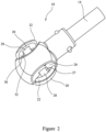
FIG. 2 : Illustrates a top view of the first construction of the connector ofFIG. 1 ; -
FIG. 3 : Illustrates a cross-section of the first construction of the connector ofFIG. 1 assembled on the circular port of the gastrostomy device; -
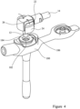
FIG. 4 : Illustrates a schematic of the first construction of the connector and the gastrostomy device prior to coupling of the connector to the gastrostomy device; -
FIG. 5 : Illustrates a schematic of the first construction of the connector and the gastrostomy device after coupling of the connector to the gastrostomy device; -
FIGs. 6a-d : Illustrates a perspective view of a lock member attached to the first construction of the connector. The lock member is used to prevent the inadvertent decoupling of the connector from the circular port of the gastrostomy device; -
FIGs. 7a-b : Illustrate a port closure member for a gastrostomy device. The port is shown in an open configuration inFIG. 7a ; and a closed configuration inFIG. 7b ; -
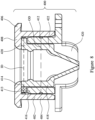
FIG. 8 : Illustrates a cross-sectional view of an exemplary construction of a gastrostomy device in which a duckbill valve is inaccessible to the user. -
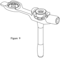
FIG. 9 : Illustrates a schematic of the construction shown inFIG. 8 . -
FIGs. 1 to 6 illustrate a first construction of aconnector 10 according to the first aspect of the invention. The connector includes a tubular fluid conduit having afirst end 12 configured for connection with anorifice 102 defined in thecircular port 104 of agastrostomy device 100. The fluid conduit also includes asecond end 14 configured for connection to an enteral feeding solution supply tube (not shown). In the construction shown, the fluid conduit is generally cylindrical and has a circular cross section. Thefirst end 12 is substantially perpendicular to thesecond end 14. In other constructions, the fluid conduit is straight, such that thefirst end 12 and thesecond end 14 are in-line with each other. - In the construction shown, the
first end 12 of the fluid conduit has a terminally-located orifice-connectingportion 18 that is nozzle-shaped or tapered. This portion forms a tapered connection with the inner surface of theorifice 102. - The connector includes a pair of
arms 20 circumferentially arranged about thefirst end 12 of the conduit. In the construction shown, the arms are positioned on opposing sides of thefirst end 12 of the conduit. Each arm includes a firstfree end 22 and a secondfree end 24. - Each
arm 20 is connected to theouter wall 26 of thefirst end 12 of the fluid conduit via aflexible bridge 28. This flexible bridge defines a pivot about which the first and second free ends of each arm can be pivoted. Agap 27 is defined between theouter wall 26 and theinner wall 30 of each arm. - Each arm is connected such that the terminally-located orifice-connecting
portion 18 extends a distance beyond the secondfree end 24 of each arm, thereby enabling the terminally-located orifice-connectingportion 18 to be inserted into theorifice 102. - In the construction shown, the
outer wall 26 of the first end of the fluid conduit and theinner wall 30 of eacharm 20 are substantially parallel, in both the coupled and decoupled configurations. - The second
free end 24 of each arm includes acatch 32 that is configured to releasably engage with acircumferential rim 106 extending about thecircular port 104 of thegastrostomy device 100. Thecatch 32 in the construction shown is located on theinner wall 30 of eacharm 20, and takes the form of a ledge that extends inwardly towards the outer wall of the first end of the fluid conduit. Each ledge has a rim-contactingsurface 36 that is configured to releasably engage with a ledge-contactingsurface 108 on thecircumferential rim 106. - Referring now to
FIG. 3 , in the construction of the connector shown, the rim-contactingsurface 36 and the ledge-contactingsurface 108 are provided with a corresponding angled surfaces. This creates a hook effect and improves the grip of the connector against the circumferential rim. - The
connector 10 may be molded as a unitary component from a plastic. - The
connector 10 is couplable to and decouplable from thecircular port 104 by pivoting the first and second ends of each arm at theflexible bridge 28 such that thecatch 32 on the secondfree end 24 of each arm is radially displaced into engagement or out of engagement with thecircumferential rim 106. - In use, in order to couple the
connector 10 to thecircular port 104 of the gastrostomy device, a patient or caregiver may apply an inwardly directed pressure (e.g., applied by a pinching action using the thumb and forefinger) to the outer surfaces of eacharm 20 in order to move the firstfree end 22 of each arm inwardly towards theouter wall 26 of thefirst end 12 of the fluid conduit. The direction of the applied pressure is indicated by the arrows inFIG. 4 . As a consequence of the inward movement of the firstfree end 22 of each arm, the secondfree end 24 of each arm is pivoted about theflexible bridge 28 in an outwardly direction away from theouter wall 26 of thefirst end 12 of the fluid conduit. This outward movement enables thecatch 32 on theinner wall 30 of the arm to clear thecircumferential rim 106 as the connector is pushed into contact with the gastrostomy device. When the user releases the applied pressure, the secondfree end 24 of each arm reverts to its original position. Accordingly, the rim-contactingsurface 36 of the ledge engages with the ledge-contactingsurface 108 on thecircumferential rim 106. This is shown inFIG. 5 . - Alternatively, in order to couple the
connector 10 to thecircular port 104 of the gastrostomy device, a patient or caregiver may simply push the secondfree end 24 of each arm down against thecircular port 104. The angled leading edges of thecatches 32 then push and flex thefree end 24 outwardly such that they clip over thecircumferential rim 106 as the connector is pushed into contact with the gastrostomy device. - In order to decouple the
connector 10 from thecircular port 104 of the gastrostomy device, the patient or caregiver performs a similar pinching actions as outlined above in relation to coupling the connector. The user applies an inwardly directed pressure (e.g., applied by a pinching action between the thumb and forefinger) to the outer surfaces of eacharm 20 in order to move the firstfree end 22 of each arm inwardly towards theouter wall 26 of thefirst end 12 of the fluid conduit. As a consequence, the secondfree end 24 of each arm is pivoted in an outwardly direction away from theouter wall 26 of thefirst end 12 of the fluid conduit. This outward movement enables thecatch 32 on theinner wall 30 of the arm to clear thecircumferential rim 106, enabling the connector to be decoupled from the gastrostomy device. -
FIGs. 6a-d illustrate a perspective view of alock member 200 attached to the first construction of theconnector 10. Use of thelock member 200 prevents inadvertent decoupling of the connector from the gastrostomy device. - The lock member includes an
annular collar 202 that is slidably received over thesecond end 14 of the tubular fluid conduit. The collar retains the lock member on the connector. The lock member also includes a generally disk-shapedcover portion 204 that is hingedly attached to the collar. - The
lock member 200 includes aflexible tab portion 206 that extends between the cover portion and the collar. Theflexible tab portion 206 provides a hinged connection. - A pair of spaced apart hooks 208 depend from a
first surface 210 of the cover portion. Eachhook 208 is dimensioned such that it is capable of being sandwiched within thegap 27 located between the between theouter wall 26 of the fluid conduit and theinner wall 30 of eacharm 20 of the connector. - The
curved end 212 of eachhook 208 is configured to hook around at least a part of eachflexible bridge 28. - As shown in
FIGs. 6a-6b , thelock member 200 is molded as a unitary plastic component, with theflexible arm 206 being biased to a position in which thefirst surface 210 from which thehooks 208 depend is positioned substantially perpendicular to thefirst end 12 of the tubular fluid conduit, when the connector is not coupled to the gastrostomy device. This biasing is achieved as a result of theflexible tab portion 206 being curved. - As shown in
FIG. 6b , once the connector has been connected to the port of the gastrostomy device, and enteral feeding is taking place, the user pushes against thesecond surface 216 of the cover to rotate the cover by 90° in a clockwise direction. This causes theflexible tab portion 206 to become substantially straight and thehooks 208 are forced into thegap 27. This locked configuration is shown inFIG. 6c . In this position, thecurved end 212 of each hook becomes hooked around eachflexible bridge 28. As shown inFIG. 6d . - The
hooks 208 act to prevent thesecond end 24 of eacharm 20 being pivoted at theflexible bridge 28, and hence radially displaced out of engagement with thecircumferential rim 106 of the circular port. Essentially, each arm is locked in the coupled configuration. - When the user wants to decouple the connector from the gastrostomy device, he/she will grip the cover and rotate it by 90° in an anti-clockwise direction, to its original position.
-
FIGs. 7a-7b illustrate a perspective view of aport closure member 300 connected to agastrostomy device 100 according to the third aspect of the invention.FIG. 7a shows thecircular port 104 open.FIG. 7b shows thecircular port 104 closed by theport closure member 300. The port is closed when enteral feeding is not taking place. - The
port closure member 300 comprises acap 302 that is tethered by aflexible strip 304 to the gastrostomy device. Thecap 302 includes a centrally located, generallycylindrical plug 306 that is dimensioned to be press-fitted into thecircular port 104 of the device. This connection forms a fluid-tight seal. The cap also includes aring member 308 that is radially disposed about theplug 306. Thering member 308 has acircumferential groove 310 dimensioned to receive thecircumferential rim 106 provided on thecircular port 104 of thegastrostomy device 100. The connection between thecircular groove 310 and thecircumferential rim 106 is shown in detail in the cross-sectional drawing,FIG. 7b . -
FIG. 8 illustrates a gastrostomy device which is not according to the invention.
Thecircular port assembly 400 of thegastrostomy device 100 consists of an interlock formed by two plastic components that are connected together. For example, the components may be ultrasonically welded together, or connected via a press-fit. A non-return duckbill valve is trapped within the assembly. - The assembly includes a
first component 402 that includes a firstcylindrical wall member 404 having an inner diameter (ID) and acircumferential rim 406, aportion 408 of which extends inwardly. - The assembly also includes second component 410 that includes a second
cylindrical wall member 412 having an outer diameter (OD). The OD of the secondcylindrical wall member 412 is less than the ID of the firstcylindrical wall member 404. Accordingly, the second component is nested within the first component. - A
gap 413 is provided between asurface 414 of the inwardly extendingportion 408 of thecircumferential rim 406 of the first component, and anend portion 416 of the secondcylindrical wall member 412 of the second component. - The
circular port assembly 400 also includes a non-return valve, here shown in the form of aduckbill valve 418. Theduckbill valve 418 includes aflange 420 from whichelastomeric lips 422 in the shape of a duckbill extend. - During assembly of the
port assembly 400, theflange 420 of the duckbill valve is retained within thegap 413 provided between asurface 414 of the inwardly extendingportion 408 of thecircumferential rim 406 of the first component, and anend portion 416 of the secondcylindrical wall member 412 of the second component. As this design locates the flange of the duckbill valve entirely within the interior of the circular port assembly, this prevents access to the flange. This minimises the risk of the user inadvertently causing the inward deflection of the flange, and the consequent opening of the valve.
Claims (8)
- A connector (10) for rotatably coupling an enteral feeding solution supply tube to a circular port (104) of a gastrostomy device (100), the connector (10) comprising:a fluid conduit having a first end (12) configured for connection with an orifice (102) defined in the circular port (104) to supply the enteral feeding solution to the gastrostomy device (100), and a second end (14) configured for connection to the enteral feeding solution supply tube,a pair of arms (20) circumferentially arranged around an outer wall (26) of the first end (12) of the fluid conduit, each arm (20) including a first free end (22) and a second free end (24), wherein the second free end (24) includes a catch (32) configured to releasably engage with a circumferential rim (106) on the circular port (104) anda flexible bridge (28) connecting each arm (20) to the first end (12) of the fluid conduit and about which the first and second free ends (22, 24) of each arm (20) can be pivoted,wherein the connector (10) is couplable to and decouplable from the circular port (104) by pivoting the first and second ends (22, 24) of each arm (20) at the flexible bridge (28) such that the catch (32) on the second free end (24) of each arm (20) is radially displaced into engagement or out of engagement with the rim (106),wherein the outer wall (26) of the first end (12) of the fluid conduit and an inner wall (30) of each arm (20) are substantially parallel,wherein the catch (32) is a ledge located on the inner wall (30) of the arm (20) that projects inwardly towards the first end (12) of the fluid conduit, wherein the ledge has a rim-contacting surface (36) configured to releasably engage with a ledge-contacting surface (108) of the circumferential rim (106), wherein the ledge-contacting surface (108) of the rim (106) is a sloped surface and the rim-contacting surface (36) of the ledge has a complementary sloped surface andwherein the connector (10) is moulded as a unitary component from a plastic.
- The connector (10) according to claim 1 further comprising a lock member (200) at least a part of which is configured to be sandwiched between the outer wall (26) of the fluid conduit and the inner wall (30) of each arm (20).
- The connector (10) according to claim 2 wherein the lock member (200) is removably attachable to the connector (10).
- The connector (10) according to claim 2 or 3 wherein the lock member (200) is retained on the connector (10) by a collar (202) which comprises an open ring that is made of a resilient material.
- The connector (10) according to claim 2, wherein the second end (14) of the fluid conduit is substantially perpendicular to the first end (12) of the fluid conduit, wherein the lock member (200) comprises:a collar (202) for connecting the lock member (200) to the second end (14) of the fluid conduit, anda cover portion (204) hingedly attached to the collar (202), wherein a pair of hooks (208) extend from the cover portion (204),and wherein the cover portion (204) is biased such that the surface (210) from which the hooks (208) depend is substantially perpendicular to the second end (14) of the fluid conduit.
- A feeding extension set comprisingan enteral feeding solution supply tube,a connector (10) according to any preceding claim configured for rotatably coupling the enteral feeding solution tube to a circular port (104) of a gastrostomy device (100).
- A non-surgical and non-therapeutic method of delivering an enteral fluid to a patient comprising the steps of:using a connector (10) according to any of claims 1 to 5,coupling the first end (12) of the fluid conduit to the circular port (104) of an indwelling gastrostomy device (100),coupling the second end (14) of the fluid conduit to an enteral feeding solution supply tube.
- The method of delivering an enteral fluid to a patient according to claim 7 when dependent on claim 5, wherein the method further comprises the step of positioning the pair of hooks (208) on the lock member (200) around at least part of each flexible bridge (28) to prevent the second free end (24) of each arm (20) from decoupling from the circumferential rim (106).
Applications Claiming Priority (1)
| Application Number | Priority Date | Filing Date | Title |
|---|---|---|---|
| GBGB1907070.5A GB201907070D0 (en) | 2019-05-20 | 2019-05-20 | Connector for a gastrostomy device |
Publications (4)
| Publication Number | Publication Date |
|---|---|
| EP3741350A2 EP3741350A2 (en) | 2020-11-25 |
| EP3741350A3 EP3741350A3 (en) | 2021-02-24 |
| EP3741350B1 true EP3741350B1 (en) | 2023-08-02 |
| EP3741350C0 EP3741350C0 (en) | 2023-08-02 |
Family
ID=67385331
Family Applications (1)
| Application Number | Title | Priority Date | Filing Date |
|---|---|---|---|
| EP20175499.1A Active EP3741350B1 (en) | 2019-05-20 | 2020-05-19 | Connector for a gastrostomy device |
Country Status (5)
| Country | Link |
|---|---|
| US (1) | US11707418B2 (en) |
| EP (1) | EP3741350B1 (en) |
| ES (1) | ES2954900T3 (en) |
| GB (2) | GB201907070D0 (en) |
| PL (1) | PL3741350T3 (en) |
Families Citing this family (2)
| Publication number | Priority date | Publication date | Assignee | Title |
|---|---|---|---|---|
| GB2605468B (en) * | 2021-07-02 | 2023-06-28 | Gbuk Group Ltd | Connector for a gastrostomy device |
| USD979052S1 (en) | 2021-07-23 | 2023-02-21 | Gbuk Group Limited | Fixation device for a medical tube |
Family Cites Families (79)
| Publication number | Priority date | Publication date | Assignee | Title |
|---|---|---|---|---|
| US5688254A (en) * | 1983-01-24 | 1997-11-18 | Icu Medical, Inc. | Medical connector |
| FR2635369B1 (en) | 1988-08-09 | 1990-10-05 | Degremont | DEVICE FOR QUICK, SEALED CONNECTION OF TUBES |
| IE72466B1 (en) | 1989-03-17 | 1997-04-09 | Baxter Int | Blunt-ended cannula device |
| CA2017242A1 (en) | 1989-06-21 | 1990-12-21 | James N. Mashak | Antidisconnect device for medical hoses |
| US6217564B1 (en) | 1994-02-17 | 2001-04-17 | Clinical Product Development Limited | Couplings for medical cannulae |
| JP2887574B2 (en) | 1995-12-01 | 1999-04-26 | 日本ラセン株式会社 | Corrugated tube connector |
| US6019746A (en) | 1996-05-17 | 2000-02-01 | Applied Medical Technology, Inc. | Low profile balloon feeding device |
| AUPP855099A0 (en) | 1999-02-09 | 1999-03-04 | Resmed Limited | Gas delivery connection assembly |
| US5937851A (en) | 1997-02-27 | 1999-08-17 | Respironics, Inc. | Swivel device utilizing bearing clearance to allow carbon dioxide laden exhaust |
| US5997503A (en) | 1998-02-12 | 1999-12-07 | Ballard Medical Products | Catheter with distally distending balloon |
| USD418220S (en) | 1998-03-26 | 1999-12-28 | Applied Medical Technology, Inc. | Low profile balloon feeding device |
| US6045536A (en) | 1999-02-24 | 2000-04-04 | Sherwood Services, A.G. | Securing device for a low profile gastrostomy tube |
| ATE424175T1 (en) | 1999-12-09 | 2009-03-15 | Kimberly Clark Co | SILICONE ELASTOMERIC MATERIAL FOR USE WITH ENTERAL FEEDING DEVICE |
| US6419670B1 (en) | 2000-02-16 | 2002-07-16 | W. Cary Dikeman | Gastrostomy tube set |
| US6458106B1 (en) | 2000-02-17 | 2002-10-01 | Sherwood Services, Ag | Low profile jejunal adapter for a gastrojejunal feeding system |
| US6908449B2 (en) | 2000-12-19 | 2005-06-21 | Kimberly-Clark Worldwide, Inc. | Sealing valve assembly for medical products |
| WO2002066108A1 (en) | 2001-02-15 | 2002-08-29 | Sherwood Services, Ag | Securing device for a low profile gastrostomy tube |
| US20030045841A1 (en) | 2001-08-31 | 2003-03-06 | Palcisko William M. | Feeding device with secondary stop tab |
| GB2410305B (en) | 2001-09-04 | 2005-12-07 | Clinical Product Dev Ltd | Couplings for medical fluid delivery systems |
| US6923791B2 (en) | 2003-03-31 | 2005-08-02 | Sterling Medivations, Inc. | Infusion device having offset flow path |
| JP4558290B2 (en) * | 2003-08-20 | 2010-10-06 | 川澄化学工業株式会社 | Injection device and medical device |
| US20050090805A1 (en) | 2003-10-28 | 2005-04-28 | Shaw Scott R. | Reconnectable disconnect device for fluid transfer line |
| US7494481B2 (en) | 2004-12-03 | 2009-02-24 | Medtronic Minimed, Inc. | Multi-position infusion set device and process |
| JP4292145B2 (en) | 2004-11-19 | 2009-07-08 | 株式会社ジェイ・エム・エス | Lock connector device for channel communication |
| US7448653B2 (en) | 2005-06-10 | 2008-11-11 | Value Plastics, Inc. | Female connector for releasable coupling with a male connector defining a fluid conduit |
| DE102007011220B3 (en) | 2007-03-01 | 2008-01-24 | Masterflex Ag | Medical multi-lumen device used as a breathing device for animals and humans comprises sections in the longitudinal direction with tubes extending through the reusable section up to a part of the disposable section |
| EP3037117B1 (en) | 2007-10-12 | 2017-12-20 | DEKA Products Limited Partnership | Blood line connector |
| US20090254039A1 (en) | 2007-12-21 | 2009-10-08 | O'brien Nicole Sams | Designer accessory for use with an intracorporeal medical device |
| US20090188575A1 (en) | 2008-01-28 | 2009-07-30 | Colder Products Company | Quick Connect/Disconnect Coupling Assemblies |
| EP2095841B1 (en) | 2008-02-29 | 2012-11-07 | F. Hoffmann-La Roche AG | Connection system for connecting a fluid line to a fluid reservoir |
| US8235426B2 (en) | 2008-07-03 | 2012-08-07 | Nordson Corporation | Latch assembly for joining two conduits |
| WO2010075032A2 (en) | 2008-12-22 | 2010-07-01 | Cook Incorporated | Low-profile external fitting |
| US9259564B2 (en) | 2009-01-22 | 2016-02-16 | Avent, Inc. | Enteral feeding assembly with lock assembly |
| KR20120104391A (en) | 2009-12-23 | 2012-09-20 | 노드슨 코포레이션 | Male bayonet connector |
| US9132064B2 (en) | 2009-12-23 | 2015-09-15 | Avent, Inc. | Enteral feeding catheter assembly incorporating an indicator |
| CN103124581A (en) | 2010-07-23 | 2013-05-29 | 梅德拉控股公司 | Enteral feeding assembly |
| US8449528B2 (en) | 2010-07-30 | 2013-05-28 | Kimberly-Clark Worldwide Inc. | Enteral feeding extension set connector |
| JP2012075495A (en) | 2010-09-30 | 2012-04-19 | Jms Co Ltd | Medical use knife connector |
| US8177742B1 (en) | 2010-12-23 | 2012-05-15 | Kimberly-Clark Wordwide, Inc. | Inflatable retention system for an enteral feeding device |
| EP2497525B1 (en) | 2011-03-09 | 2014-06-04 | Covidien LP | Connector for connecting a syringe to a gastrostomy tube |
| CA2798194C (en) * | 2011-12-09 | 2019-03-26 | Earl Christian, Jr. | Quick-connect tube coupling |
| US9033930B2 (en) | 2011-12-22 | 2015-05-19 | Avent, Inc. | Base for an enteral feeding device |
| JP6094829B2 (en) | 2012-04-13 | 2017-03-15 | 株式会社ジェイ・エム・エス | Male connector with locking mechanism |
| WO2013154050A1 (en) | 2012-04-13 | 2013-10-17 | 株式会社ジェイ・エム・エス | Male connector equipped with lock mechanism |
| US9700489B2 (en) | 2012-07-13 | 2017-07-11 | Avent, Inc. | Feeding tube tip reinforcement |
| JP6003361B2 (en) | 2012-08-02 | 2016-10-05 | 住友ベークライト株式会社 | Medical connector and medical reservoir |
| US9381338B2 (en) * | 2012-11-30 | 2016-07-05 | Avent, Inc. | Medical connector with a reversibly deformable lobe |
| US9364652B2 (en) | 2012-11-30 | 2016-06-14 | Avent, Inc. | Medical connector with lift tabs |
| US9433770B2 (en) | 2012-12-28 | 2016-09-06 | Avent, Inc. | Medical connector with spanning arms |
| US9956366B2 (en) | 2013-01-14 | 2018-05-01 | Avent, Inc. | Bridle delivery system, method, and apparatus for securing nasal tubes |
| DE102013001631A1 (en) | 2013-01-31 | 2014-07-31 | Eugen Forschner Gmbh | Device for connecting fluid-guiding pipeline with connector in commercial vehicle in automobile industry, has locking element designed as bilateral lever with operating arm, and rod comprising locking hook and designed as springy element |
| US9561158B2 (en) | 2013-03-15 | 2017-02-07 | Applied Medical Technology, Inc. | Bridle catheter with illuminating end |
| US9814871B2 (en) | 2013-03-15 | 2017-11-14 | Bayer Healthcare Llc | Connector assembly for syringe system |
| WO2014145694A1 (en) | 2013-03-15 | 2014-09-18 | Applied Medical Technology, Inc. | Endotracheal tube retention system |
| ITTO20130411A1 (en) | 2013-05-23 | 2014-11-24 | Borla Ind | CANNULA WITH LOCKING DEVICE FOR MEDICAL LINES |
| DE102013105611B4 (en) | 2013-05-31 | 2016-12-01 | MEDTRONIC medizinisch-elektronische Geräte-Gesellschaft mit beschränkter Haftung | Coupling device for connecting hoses |
| GB2519530A (en) | 2013-10-22 | 2015-04-29 | Peter James Le Cuirot | A tube connection device |
| US9414991B2 (en) | 2013-11-06 | 2016-08-16 | Becton Dickinson and Company Limited | Medical connector having locking engagement |
| US9636278B2 (en) | 2013-11-06 | 2017-05-02 | Becton Dickinson and Company Limited | System for closed transfer of fluids with a locking member |
| BR112016008690B1 (en) | 2013-12-10 | 2021-12-14 | Applied Medical Technology, Inc | BRAKE CATHETER |
| WO2015123689A1 (en) | 2014-02-17 | 2015-08-20 | The Johns Hopkins University | Catheter hub with removable extensions |
| GB201405244D0 (en) | 2014-03-24 | 2014-05-07 | T & T Devices Ltd | A nasal bridle insertion device |
| US10058693B2 (en) | 2014-05-23 | 2018-08-28 | Applied Medical Technology, Inc. | Interlock feed set coupling |
| WO2016018998A1 (en) | 2014-07-29 | 2016-02-04 | Colder Products Company | Axial tube quick coupling assembly with female and male part and perpendicular decoupling pushbutton |
| EP3204680B1 (en) | 2014-10-09 | 2023-07-26 | Colder Products Company | Female coupling device |
| WO2016086009A1 (en) | 2014-11-24 | 2016-06-02 | Kirn Medical Design, Llc | Nasal bridle clip applier and related method |
| CA2977030C (en) | 2015-02-18 | 2024-10-29 | Jms Co., Ltd. | MALE LEVER LOCKING FITTING AND MALE FITTING ASSEMBLY |
| GB201504481D0 (en) | 2015-03-17 | 2015-04-29 | Young Peter J | Improved nasogastric tube |
| US10130770B2 (en) | 2015-06-11 | 2018-11-20 | Kpr U.S., Llc | Enteral feeding syringe assembly |
| WO2017004265A1 (en) | 2015-06-30 | 2017-01-05 | Endologix, Inc. | Locking assembly for coupling guidewire to delivery system |
| JP6694501B2 (en) | 2015-07-14 | 2020-05-13 | ネオメッド, インクNeomed, Inc. | Dosage control joint for enteral fluid flow |
| JP2017108902A (en) | 2015-12-16 | 2017-06-22 | 株式会社ジェイ・エム・エス | Adapter and male luer assembly |
| EP3402454A2 (en) | 2016-01-15 | 2018-11-21 | Neomed, Inc. | Large bore enteral connector |
| DE102016101911A1 (en) | 2016-02-03 | 2017-08-03 | B. Braun Avitum Ag | Medical clutch and medical system with a medical clutch |
| USD783162S1 (en) | 2016-04-19 | 2017-04-04 | Avent, Inc. | Finger tab |
| USD783160S1 (en) | 2016-04-19 | 2017-04-04 | Avent, Inc. | Catheter connector |
| USD783161S1 (en) | 2016-04-19 | 2017-04-04 | Avent, Inc. | Catheter connector surface |
| CN108386424B (en) | 2018-03-19 | 2020-07-31 | 杨立杰 | Quick release jaw mechanism and clamping seat assembly |
| JP2019088914A (en) | 2019-03-01 | 2019-06-13 | ニプロ株式会社 | Lock member for connector connection |
-
2019
- 2019-05-20 GB GBGB1907070.5A patent/GB201907070D0/en not_active Ceased
-
2020
- 2020-05-19 EP EP20175499.1A patent/EP3741350B1/en active Active
- 2020-05-19 GB GB2007412.6A patent/GB2586690B/en active Active
- 2020-05-19 ES ES20175499T patent/ES2954900T3/en active Active
- 2020-05-19 PL PL20175499.1T patent/PL3741350T3/en unknown
- 2020-05-20 US US16/878,716 patent/US11707418B2/en active Active
Also Published As
| Publication number | Publication date |
|---|---|
| EP3741350A2 (en) | 2020-11-25 |
| GB2586690A (en) | 2021-03-03 |
| GB202007412D0 (en) | 2020-07-01 |
| GB2586690B (en) | 2023-04-26 |
| EP3741350C0 (en) | 2023-08-02 |
| GB201907070D0 (en) | 2019-07-03 |
| US11707418B2 (en) | 2023-07-25 |
| US20200368115A1 (en) | 2020-11-26 |
| PL3741350T3 (en) | 2024-01-22 |
| EP3741350A3 (en) | 2021-02-24 |
| ES2954900T3 (en) | 2023-11-27 |
Similar Documents
| Publication | Publication Date | Title |
|---|---|---|
| US10327997B2 (en) | Enteral feeding extension set connector | |
| US10864145B2 (en) | Male connector | |
| US8858533B2 (en) | Methods and systems for providing fluid communication with a gastrostomy tube | |
| EP2736584B1 (en) | Coupling for medical fluids | |
| EP2669564A2 (en) | Twist lock connector with reinforcing wing grips and reverse snap assembly | |
| US20110127767A1 (en) | Releasable Connection Assembly for Joining Tubing Sections | |
| KR102349983B1 (en) | Caps for connectors and connectors with caps | |
| JP2025511216A (en) | Medical Connectors | |
| US20220288378A1 (en) | Breakaway intra-medical tubing connector assembly | |
| JP2008539992A (en) | Connecting device for medical line | |
| US11707418B2 (en) | Connector for a gastrostomy device | |
| US9364652B2 (en) | Medical connector with lift tabs | |
| JP2016158656A (en) | Connector with cap | |
| US9381338B2 (en) | Medical connector with a reversibly deformable lobe | |
| JP2013180049A (en) | Flexible tube connection device | |
| US20260069849A1 (en) | Breakaway intra-medical tubing connector assembly | |
| US20230000725A1 (en) | Connector for a Gastrostomy Device |
Legal Events
| Date | Code | Title | Description |
|---|---|---|---|
| PUAI | Public reference made under article 153(3) epc to a published international application that has entered the european phase |
Free format text: ORIGINAL CODE: 0009012 |
|
| STAA | Information on the status of an ep patent application or granted ep patent |
Free format text: STATUS: THE APPLICATION HAS BEEN PUBLISHED |
|
| AK | Designated contracting states |
Kind code of ref document: A2 Designated state(s): AL AT BE BG CH CY CZ DE DK EE ES FI FR GB GR HR HU IE IS IT LI LT LU LV MC MK MT NL NO PL PT RO RS SE SI SK SM TR |
|
| AX | Request for extension of the european patent |
Extension state: BA ME |
|
| STAA | Information on the status of an ep patent application or granted ep patent |
Free format text: STATUS: REQUEST FOR EXAMINATION WAS MADE |
|
| PUAL | Search report despatched |
Free format text: ORIGINAL CODE: 0009013 |
|
| 17P | Request for examination filed |
Effective date: 20201217 |
|
| RBV | Designated contracting states (corrected) |
Designated state(s): AL AT BE BG CH CY CZ DE DK EE ES FI FR GB GR HR HU IE IS IT LI LT LU LV MC MK MT NL NO PL PT RO RS SE SI SK SM TR |
|
| AK | Designated contracting states |
Kind code of ref document: A3 Designated state(s): AL AT BE BG CH CY CZ DE DK EE ES FI FR GB GR HR HU IE IS IT LI LT LU LV MC MK MT NL NO PL PT RO RS SE SI SK SM TR |
|
| AX | Request for extension of the european patent |
Extension state: BA ME |
|
| RIC1 | Information provided on ipc code assigned before grant |
Ipc: A61J 15/00 20060101AFI20210115BHEP |
|
| GRAP | Despatch of communication of intention to grant a patent |
Free format text: ORIGINAL CODE: EPIDOSNIGR1 |
|
| STAA | Information on the status of an ep patent application or granted ep patent |
Free format text: STATUS: GRANT OF PATENT IS INTENDED |
|
| INTG | Intention to grant announced |
Effective date: 20230412 |
|
| RAP1 | Party data changed (applicant data changed or rights of an application transferred) |
Owner name: GBUK GROUP LIMITED |
|
| GRAS | Grant fee paid |
Free format text: ORIGINAL CODE: EPIDOSNIGR3 |
|
| GRAA | (expected) grant |
Free format text: ORIGINAL CODE: 0009210 |
|
| STAA | Information on the status of an ep patent application or granted ep patent |
Free format text: STATUS: THE PATENT HAS BEEN GRANTED |
|
| AK | Designated contracting states |
Kind code of ref document: B1 Designated state(s): AL AT BE BG CH CY CZ DE DK EE ES FI FR GB GR HR HU IE IS IT LI LT LU LV MC MK MT NL NO PL PT RO RS SE SI SK SM TR |
|
| REG | Reference to a national code |
Ref country code: GB Ref legal event code: FG4D |
|
| REG | Reference to a national code |
Ref country code: CH Ref legal event code: EP |
|
| REG | Reference to a national code |
Ref country code: DE Ref legal event code: R096 Ref document number: 602020014744 Country of ref document: DE |
|
| REG | Reference to a national code |
Ref country code: IE Ref legal event code: FG4D |
|
| U01 | Request for unitary effect filed |
Effective date: 20230818 |
|
| U07 | Unitary effect registered |
Designated state(s): AT BE BG DE DK EE FI FR IT LT LU LV MT NL PT SE SI Effective date: 20230824 |
|
| REG | Reference to a national code |
Ref country code: NO Ref legal event code: T2 Effective date: 20230802 Ref country code: ES Ref legal event code: FG2A Ref document number: 2954900 Country of ref document: ES Kind code of ref document: T3 Effective date: 20231127 |
|
| REG | Reference to a national code |
Ref country code: GR Ref legal event code: EP Ref document number: 20230401978 Country of ref document: GR Effective date: 20231211 |
|
| PG25 | Lapsed in a contracting state [announced via postgrant information from national office to epo] |
Ref country code: IS Free format text: LAPSE BECAUSE OF FAILURE TO SUBMIT A TRANSLATION OF THE DESCRIPTION OR TO PAY THE FEE WITHIN THE PRESCRIBED TIME-LIMIT Effective date: 20231202 |
|
| PG25 | Lapsed in a contracting state [announced via postgrant information from national office to epo] |
Ref country code: RS Free format text: LAPSE BECAUSE OF FAILURE TO SUBMIT A TRANSLATION OF THE DESCRIPTION OR TO PAY THE FEE WITHIN THE PRESCRIBED TIME-LIMIT Effective date: 20230802 Ref country code: IS Free format text: LAPSE BECAUSE OF FAILURE TO SUBMIT A TRANSLATION OF THE DESCRIPTION OR TO PAY THE FEE WITHIN THE PRESCRIBED TIME-LIMIT Effective date: 20231202 Ref country code: HR Free format text: LAPSE BECAUSE OF FAILURE TO SUBMIT A TRANSLATION OF THE DESCRIPTION OR TO PAY THE FEE WITHIN THE PRESCRIBED TIME-LIMIT Effective date: 20230802 |
|
| PG25 | Lapsed in a contracting state [announced via postgrant information from national office to epo] |
Ref country code: SM Free format text: LAPSE BECAUSE OF FAILURE TO SUBMIT A TRANSLATION OF THE DESCRIPTION OR TO PAY THE FEE WITHIN THE PRESCRIBED TIME-LIMIT Effective date: 20230802 Ref country code: RO Free format text: LAPSE BECAUSE OF FAILURE TO SUBMIT A TRANSLATION OF THE DESCRIPTION OR TO PAY THE FEE WITHIN THE PRESCRIBED TIME-LIMIT Effective date: 20230802 Ref country code: CZ Free format text: LAPSE BECAUSE OF FAILURE TO SUBMIT A TRANSLATION OF THE DESCRIPTION OR TO PAY THE FEE WITHIN THE PRESCRIBED TIME-LIMIT Effective date: 20230802 Ref country code: SK Free format text: LAPSE BECAUSE OF FAILURE TO SUBMIT A TRANSLATION OF THE DESCRIPTION OR TO PAY THE FEE WITHIN THE PRESCRIBED TIME-LIMIT Effective date: 20230802 |
|
| REG | Reference to a national code |
Ref country code: DE Ref legal event code: R097 Ref document number: 602020014744 Country of ref document: DE |
|
| PLBE | No opposition filed within time limit |
Free format text: ORIGINAL CODE: 0009261 |
|
| STAA | Information on the status of an ep patent application or granted ep patent |
Free format text: STATUS: NO OPPOSITION FILED WITHIN TIME LIMIT |
|
| 26N | No opposition filed |
Effective date: 20240503 |
|
| U20 | Renewal fee for the european patent with unitary effect paid |
Year of fee payment: 5 Effective date: 20240531 |
|
| PG25 | Lapsed in a contracting state [announced via postgrant information from national office to epo] |
Ref country code: MC Free format text: LAPSE BECAUSE OF FAILURE TO SUBMIT A TRANSLATION OF THE DESCRIPTION OR TO PAY THE FEE WITHIN THE PRESCRIBED TIME-LIMIT Effective date: 20230802 |
|
| PG25 | Lapsed in a contracting state [announced via postgrant information from national office to epo] |
Ref country code: MC Free format text: LAPSE BECAUSE OF FAILURE TO SUBMIT A TRANSLATION OF THE DESCRIPTION OR TO PAY THE FEE WITHIN THE PRESCRIBED TIME-LIMIT Effective date: 20230802 |
|
| U20 | Renewal fee for the european patent with unitary effect paid |
Year of fee payment: 6 Effective date: 20250527 |
|
| PGFP | Annual fee paid to national office [announced via postgrant information from national office to epo] |
Ref country code: PL Payment date: 20250430 Year of fee payment: 6 |
|
| PGFP | Annual fee paid to national office [announced via postgrant information from national office to epo] |
Ref country code: GB Payment date: 20250528 Year of fee payment: 6 Ref country code: ES Payment date: 20250611 Year of fee payment: 6 |
|
| PGFP | Annual fee paid to national office [announced via postgrant information from national office to epo] |
Ref country code: NO Payment date: 20250530 Year of fee payment: 6 |
|
| PGFP | Annual fee paid to national office [announced via postgrant information from national office to epo] |
Ref country code: GR Payment date: 20250523 Year of fee payment: 6 |
|
| PGFP | Annual fee paid to national office [announced via postgrant information from national office to epo] |
Ref country code: CH Payment date: 20250601 Year of fee payment: 6 |
|
| PGFP | Annual fee paid to national office [announced via postgrant information from national office to epo] |
Ref country code: TR Payment date: 20250512 Year of fee payment: 6 |
|
| PGFP | Annual fee paid to national office [announced via postgrant information from national office to epo] |
Ref country code: IE Payment date: 20250528 Year of fee payment: 6 |
|
| PG25 | Lapsed in a contracting state [announced via postgrant information from national office to epo] |
Ref country code: CY Free format text: LAPSE BECAUSE OF FAILURE TO SUBMIT A TRANSLATION OF THE DESCRIPTION OR TO PAY THE FEE WITHIN THE PRESCRIBED TIME-LIMIT; INVALID AB INITIO Effective date: 20200519 |
|
| PG25 | Lapsed in a contracting state [announced via postgrant information from national office to epo] |
Ref country code: HU Free format text: LAPSE BECAUSE OF FAILURE TO SUBMIT A TRANSLATION OF THE DESCRIPTION OR TO PAY THE FEE WITHIN THE PRESCRIBED TIME-LIMIT; INVALID AB INITIO Effective date: 20200519 |