EP3741285A1 - Diverter valve assembly, dishwasher, and household appliance - Google Patents
Diverter valve assembly, dishwasher, and household appliance Download PDFInfo
- Publication number
- EP3741285A1 EP3741285A1 EP19741641.5A EP19741641A EP3741285A1 EP 3741285 A1 EP3741285 A1 EP 3741285A1 EP 19741641 A EP19741641 A EP 19741641A EP 3741285 A1 EP3741285 A1 EP 3741285A1
- Authority
- EP
- European Patent Office
- Prior art keywords
- water
- diverter valve
- water outlet
- inlet
- baffle
- Prior art date
- Legal status (The legal status is an assumption and is not a legal conclusion. Google has not performed a legal analysis and makes no representation as to the accuracy of the status listed.)
- Granted
Links
Images













Classifications
-
- A—HUMAN NECESSITIES
- A47—FURNITURE; DOMESTIC ARTICLES OR APPLIANCES; COFFEE MILLS; SPICE MILLS; SUCTION CLEANERS IN GENERAL
- A47L—DOMESTIC WASHING OR CLEANING; SUCTION CLEANERS IN GENERAL
- A47L15/00—Washing or rinsing machines for crockery or tableware
- A47L15/42—Details
- A47L15/4214—Water supply, recirculation or discharge arrangements; Devices therefor
- A47L15/4219—Water recirculation
- A47L15/4221—Arrangements for redirection of washing water, e.g. water diverters to selectively supply the spray arms
-
- A—HUMAN NECESSITIES
- A47—FURNITURE; DOMESTIC ARTICLES OR APPLIANCES; COFFEE MILLS; SPICE MILLS; SUCTION CLEANERS IN GENERAL
- A47L—DOMESTIC WASHING OR CLEANING; SUCTION CLEANERS IN GENERAL
- A47L15/00—Washing or rinsing machines for crockery or tableware
- A47L15/42—Details
- A47L15/4278—Nozzles
-
- A—HUMAN NECESSITIES
- A47—FURNITURE; DOMESTIC ARTICLES OR APPLIANCES; COFFEE MILLS; SPICE MILLS; SUCTION CLEANERS IN GENERAL
- A47L—DOMESTIC WASHING OR CLEANING; SUCTION CLEANERS IN GENERAL
- A47L15/00—Washing or rinsing machines for crockery or tableware
- A47L15/42—Details
- A47L15/4285—Water-heater arrangements
-
- A—HUMAN NECESSITIES
- A47—FURNITURE; DOMESTIC ARTICLES OR APPLIANCES; COFFEE MILLS; SPICE MILLS; SUCTION CLEANERS IN GENERAL
- A47L—DOMESTIC WASHING OR CLEANING; SUCTION CLEANERS IN GENERAL
- A47L15/00—Washing or rinsing machines for crockery or tableware
- A47L15/42—Details
- A47L15/4291—Recovery arrangements, e.g. for the recovery of energy or water
Definitions
- the present disclosure relates to a technical field of household appliances, and more particularly to a diverter valve assembly, a dishwasher, and a household appliance.
- a dishwasher may be usually provided with a heating device that heats washing water, so that high-temperature washing water can wash away contaminants on the tableware and supply heat to the tableware. Therefore, the dishwasher system can obtain a high cleaning and drying rate in a short washing time.
- the heating device when the washing water passes through the heating device, the flow resistance in the water channel is large, which may cause spray pressure of a spray arm of the dishwasher to drop or cause power consumption of a washing pump to increase.
- the heating process only takes part of the total washing time of the dishwasher.
- the heating system is directly connected to the washing water circulation flow path, during a non-heating period, the loss due to the resistance when the water flows through the heating device may cause the spray pressure of the spray arm to decrease and the washing water flow to decrease, resulting in a poor washing effect.
- the present disclosure provides a diverter valve assembly, a dishwasher, and a household appliance.
- the diverter valve assembly includes a housing and a diverter valve.
- the housing defines a water diversion chamber therein, and is provided with a water inlet, a water return port, a first water outlet, and a second water outlet.
- the diverter valve is disposed in the water diversion chamber and configured to partition the water diversion chamber into a first water diversion chamber and a second water diversion chamber.
- the first water diversion chamber is communicated with the water inlet.
- the diverter valve is rotatable in the water diversion chamber to communicate the first water diversion chamber with the water inlet and the first water outlet and communicate the second water diversion chamber with the second water outlet and the water return port, or to block the water inlet from the first water outlet and communicate the first water diversion chamber with the water inlet and the second water outlet.
- a heating device may be connected in a pipeline connecting the first water outlet and the water return port, and a spray arm of the household appliance may be connected to the second water outlet through a pipeline. Therefore, when water needs to be heated, the diverter valve can rotate, so that the first water diversion chamber is communicated with the water inlet and the first water outlet. In such a case, water entering through the water inlet can flow out from the first water outlet via the first water diversion chamber and be heated by the heating device, and the water heated by the heating device can flow into the second water diversion chamber from the water return port and flow to the spray arm from the second water outlet to be sprayed.
- the diverter valve When water does not need to be heated, the diverter valve can rotate, so that the water inlet is blocked from the first water outlet. In such a case, water entering through the water inlet can flow directly from the second water outlet to the spray arm via the first water diversion chamber and be sprayed. That is, the water does not pass through the heating device, which can reduce the resistance in a water flow system during a non-heating period, solve problems of huge power consumption of a washing pump and long washing time, and hence improve the system washing performance of the household appliance.
- the diverter valve has a first baffle, and the first baffle can open or close the first water outlet when the diverter valve rotates.
- the first baffle is provided with a water through hole, and when the diverter valve rotates, the first baffle can communicate the first water outlet with the first water diversion chamber by means of the water through hole.
- the diverter valve has a partition baffle, the partition baffle partitions the water diversion chamber into a first water diversion chamber and a second water diversion chamber, and the partition baffle can rotate in the water diversion chamber to communicate the water inlet with the first water outlet or block the water inlet from the first water outlet.
- the partition baffle includes a baffle body and two baffle connecting pieces connected to both sides of the baffle body, and the two baffle connecting pieces are each attached to an inner wall of the water diversion chamber.
- the baffle connecting pieces are arcuately connected to the inner wall of the water diversion chamber.
- the diverter valve has a second baffle, and the second baffle can open or close the second water outlet when the diverter valve rotates.
- a plurality of second water outlets are provided, a plurality of second baffles are provided, and the number of the second baffles is identical to the number of the second water outlets.
- two second water outlets are provided, and two second baffles are provided; the two second water outlets are spaced apart from each other, and the two second baffles are spaced apart from each other.
- the diverter valve includes a fixing portion, and the second baffle is detachably mounted to the fixing portion.
- the housing is provided with a channel, and the channel is communicated with the second water outlet;
- the second baffle includes a bottom plate and a first fitting portion extending upwards from the bottom plate;
- the fixing portion is formed with a second fitting portion fitted with the first fitting portion; when the diverter valve rotates, the second baffle can open or close an entry of the channel through the bottom plate to open or close the second water outlet.
- the diverter valve has a third baffle, and the third baffle can open or close the water return port when the diverter valve rotates.
- the diverter valve assembly includes a driving mechanism, and the driving mechanism is connected to the diverter valve and configured to drive the diverter valve to rotate.
- the diverter valve assembly includes a sensor; the driving mechanism includes a driving portion and a transmission portion; the transmission portion connects the driving portion to the diverter valve and includes a transmission member; and the sensor is used to detect a position of the transmission member.
- the driving portion includes an electric motor; the diverter valve includes a driving rod, and the driving rod extends downwards from a top of the diverter valve; the diverter valve is connected to the transmission member through the driving rod.
- the housing includes a lower housing and an upper housing, and the lower housing is connected to the upper housing.
- the lower housing is provided with the water inlet, the water return port, and the second water outlet; the upper housing is provided with the first water outlet.
- the household appliance includes: a chamber body, a spray arm, a heating device, and the diverter valve assembly according to any one of the above embodiments.
- the chamber body defines a chamber therein.
- the spray arm is at least partially disposed in the chamber.
- the second water outlet is connected to the spray arm.
- the heating device is connected to the first water outlet and the water return port.
- the heating device when the diverter valve assembly is applied to the household appliance, the heating device may be connected in a pipeline connecting the first water outlet and the water return port, and the spray arm of the household appliance may be connected to the second water outlet through a pipeline. Therefore, when water needs to be heated, the diverter valve can rotate, so that the first water diversion chamber is communicated with the water inlet and the first water outlet. In such a case, water entering through the water inlet can flow out from the first water outlet via the first water diversion chamber and be heated by the heating device, and the water heated by the heating device can flow into the second water diversion chamber from the water return port and flow to the spray arm from the second water outlet to be sprayed.
- the diverter valve When water does not need to be heated, the diverter valve can rotate, so that the water inlet is blocked from the first water outlet. In such a case, water entering through the water inlet can flow directly from the second water outlet to the spray arm via the first water diversion chamber and be sprayed. That is, the water does not pass through the heating device, which can reduce the resistance in a water flow system during a non-heating period, solve problems of huge power consumption of a washing pump and long washing time, and hence improve the system washing performance of the household appliance.
- the dishwasher includes: a washing inner container, a spray arm, a heating device, and a diverter valve.
- the washing inner container is provided with a washing outlet.
- the spray arm is disposed in the washing inner container and provided with a spray inlet.
- the heating device is configured to heat washing water, and has a to-be-heated water inlet and a heated water outlet.
- the diverter valve is provided with a water inlet, a second water outlet, a first water outlet, and a water return port.
- the water inlet is connected to the washing outlet, the second water outlet is connected to the spray inlet, the first water outlet is connected to the to-be-heated water inlet, and the water return port is connected to the heated water outlet.
- the dishwasher includes at least two working modes. In a first mode, the water inlet of the diverter valve is communicated with the second water outlet. In a second mode, the water inlet of the diverter valve is communicated with the first water outlet, and the water return port is communicated with the
- the diverter valve By providing the diverter valve, the washing water does not flow through the heating device during a non-heating period, such that the water flow resistance can be reduced, the washing performance can be improved, and the system piping is simple and compact.
- a plurality of spray arms are provided, and the spray inlet of each spray arm is communicated with the second water outlet.
- a plurality of spray arms are provided, a plurality of second water outlets are provided, and each second water outlet is communicated with the spray inlet of at least one spray arm.
- a plurality of second water outlets are provided; in the first mode, the water inlet is selectively communicated with at least one second water outlet; in the second mode, the water return port is selectively communicated with at least one second water outlet.
- two second water outlets are provided.
- the water inlet is communicated with one of the second water outlets, or the water inlet is communicated with the other one of the second water outlets, or the water inlet is simultaneously communicated with both of the second water outlets.
- the water return port is communicated with one of the second water outlets, or the water inlet is communicated with the other one of the second water outlets, or the water inlet is simultaneously communicated with both of the second water outlets.
- the spray arm includes: a lower spray arm provided at a lower part inside the washing inner container; an upper spray arm provided at an upper part inside the washing inner container; and a middle spray arm provided at a middle part inside the washing inner container.
- two second water outlets are provided; a spray inlet of the lower spray arm is communicated with one of the second water outlets; a spray inlet of the upper spray arm and a spray inlet of the middle spray arm are communicated with the other one of the second water outlets.
- three second water outlets are provided, and the three second water outlets are connected to a spray inlet of the lower spray arm, a spray inlet of the upper spray arm, and a spray inlet of the middle spray arm, respectively.
- the heating device includes a compressor, a condenser, a throttling device, and an evaporator that are sequentially connected end to end to constitute a refrigerant cycle.
- the condenser defines a first liquid flow channel and a second liquid flow channel therein; two ends of the first liquid flow channel are provided with the to-be-heated water inlet and the heated water outlet, respectively; two ends of the second liquid flow channel are communicated with the compressor and the throttling device, respectively.
- first and second are used herein for purposes of description and are not intended to indicate or imply relative importance or significance or to imply the number of indicated technical features.
- the feature defined with “first” and “second” may explicitly or implicitly comprise one or more this feature.
- "a plurality of' means two or more than two, unless specified otherwise.
- the terms “mounted,” “connected,” “coupled,” and the like are used broadly, and may be, for example, fixed connections, detachable connections, or integral connections; may also be mechanical or electrical connections; may also be direct connections or indirect connections via intervening structures; may also be inner communications or mutual interaction of two elements, which can be understood by those skilled in the art according to specific situations.
- a diverter valve assembly 10 can be applied to a household appliance 200 according to an embodiment of the present disclosure.
- the household appliance 200 may be a dishwasher or other household cleaning apparatuses that require the use of liquids (such as water).
- the household appliance 200 includes the diverter valve assembly 10, a chamber body 20, a spray arm 30, and a heating device 40.
- the chamber body 20 defines a chamber 21 therein.
- the spray arm 30 is at least partially disposed in the chamber 21.
- the spray arm 30 is provided with a plurality of spray holes (not shown).
- a washing solution can be sprayed into the chamber 21 through the plurality of spray holes, to wash items (e.g., tableware) in the chamber 21.
- the spray arm 30 includes a first spray arm 31, a second spray arm 32, and a third spray arm 33 spaced apart from one another.
- the first spray arm 31, the second spray arm 32, and the third spray arm 33 may be an upper spray arm, a middle spray arm, and a lower spray arm in sequence.
- the first spray arm 31, the second spray arm 32, and the third spray arm 33 can be used to clean items located at different positions in the chamber 21, respectively.
- the heating device 40 is used to heat washing water, and the heated washing water can be sprayed through the spray holes of the spray arm 30.
- the diverter valve assembly 10 includes a housing 11 and a diverter valve 12.
- the housing 11 defines a water diversion chamber 111 therein.
- the housing 11 is provided with a water inlet 112, a water return port 113, a first water outlet 114, and a second water outlet 115.
- the first water outlet 114 can be communicated with the water return port 113 through an external pipeline of the housing 11.
- the diverter valve 12 is disposed in the water diversion chamber 111 and can partition the water diversion chamber 111 into a first water diversion chamber 1111 and a second water diversion chamber 1112 which are spaced apart from each other.
- the first water diversion chamber 1111 is communicated with the water inlet 112.
- the diverter valve 12 can rotate in the water diversion chamber 111 to communicate the first water diversion chamber 1111 with the water inlet 112 and the first water outlet 114 and communicate the second water diversion chamber 1112 with the second water outlet 115 and the water return port 113, or to block the water inlet 112 from the first water outlet 114 and communicate the first water diversion chamber 1111 with the water inlet 112 and the second water outlet 115.
- the diverter valve assembly 10 can achieve a first state and a second state.
- the first state and the second state are not simultaneous.
- the diverter valve 12 rotates to communicate the first water diversion chamber 1111 with the water inlet 112 and the first water outlet 114
- the second water diversion chamber 1112 can be communicated with the second water outlet 115 and the water return port 113, thereby realizing the first state of the water valve assembly 10.
- water passing through the water inlet 112 can flow out from the first water outlet 114 via the first water diversion chamber 1111, and the water flowing out from the first water outlet 114 can flow into the second water diversion chamber 1112 via the water return port 113 and flow out from the second water outlet 115 via the second water diversion chamber 1112.
- the diverter valve assembly 10 can be set in the first state, and at this time the household appliance 200 can be considered to be in a heating mode.
- the diverter valve 12 rotates to block the water inlet 112 from the first water outlet 114, the first water diversion chamber 1111 is communicated with the water inlet 112 and the second water outlet 115, thereby realizing the second state of the water valve assembly 10. In such a case, water passing through the water inlet 112 can directly flow out from the second water outlet 115 via the first water diversion chamber 1111.
- the diverter valve assembly 10 can be set in the second state, and at this time the household appliance 200 can be considered to be in a non-heating mode.
- the household appliance 200 further includes a water sump 50 and a washing pump 60.
- the washing solution sprayed onto the washing items can be collected in the water sump 50 at the bottom of the chamber 21.
- a washing outlet 201 is provided in the bottom of the water sump 50.
- the washing solution flows out from the washing outlet 201.
- An inlet of the washing pump 60 is communicated with the washing outlet 201, and an outlet of the washing pump 60 is communicated with the water inlet 112, so that the washing pump 60 offers power to the circulation of the washing solution.
- the heating device 40 is connected to the first water outlet 114 and the water return port 113 through pipelines.
- the spray arm 30 can be connected to the second water outlet 115 through a pipeline, so that when the water needs to be heated, the diverter valve 12 can be rotated to communicate the first water diversion chamber 1111 with the water inlet 112 and the first water outlet 114.
- the water entering through the water inlet 112 can flow out from the first water outlet 114 via the first water diversion chamber 1111 and be heated by the heating device 40; the water heated by the heating device 40 can flow from the water return port 113 into the second water diversion chamber 1112 and flow from the second water outlet 115 to the spray arm 30 for spraying.
- the diverter valve 12 can be rotated to block the water inlet 112 from the first water outlet 114.
- the water entering through the water inlet 112 can directly flow from the second water outlet 115 via the first water diversion chamber 1111 to the spray arm 30 for spraying, that is, the water does not flow through the heating device 40, such that the resistance in a water flow system during a non-heating period can be reduced, problems of huge power consumption of the washing pump 60 and long washing time can be solved, and hence the system washing performance of the household appliance 200 can be improved.
- the external pipeline connecting the first water outlet 114 and the water return port 113 may also be provided with other apparatuses (for example, a plurality of heating devices), which can be set according to specific circumstances.
- the heating device 40 employs a heat pump system, which includes a compressor 41, a condenser 42, a throttling device 43, and an evaporator 44.
- the compressor 41, the condenser 42, the throttling device 43, and the evaporator 44 are connected in sequence through pipelines and constitute a closed circulation system, and a refrigerant circulates in the closed circulation system.
- the diverter valve 12 may also close the water return port 113 to block the second water outlet 115 from the water return port 113.
- a space corresponding to the first water diversion chamber 1111 and a space corresponding to the second water diversion chamber 1112 are both variable.
- a pressure of a liquid entering the first water diversion chamber 1111 from the water inlet 112 is greater than a pressure of a liquid entering the second water diversion chamber 1112 from the water return port 113 (a pressure drop loss due to liquid flow). Therefore, the first water diversion chamber 1111 can be regarded as a high pressure chamber, and the second water diversion chamber 1112 can be regarded as a low pressure chamber.
- the diverter valve 12 has a first baffle 121.
- the first baffle 121 can open or close the first water outlet 114 when the diverter valve 12 rotates.
- the first baffle 121 is offset from the first water outlet 114 as the diverter valve 12 rotates, thereby communicating the water inlet 112 and the first water outlet 114.
- the first baffle 121 closes the first water outlet 114 to prevent the liquid from entering the heating device 40 through the first water outlet 114.
- the shape of the first baffle 121 may be set according to specific situations.
- the first baffle 121 may be in a circular shape or an elliptical shape.
- the first baffle 121 is provided with a water through hole 1211.
- the first baffle 121 can communicate the first water outlet 114 with the first water diversion chamber 1111 by means of the water through hole 1211.
- the first baffle 121 blocks the first water outlet 114 from the first water diversion chamber 1111.
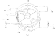
- a plurality of water through holes 1211 may be provided. For example, in an example shown in FIG. 18 , the water through hole 1211 of the first baffle 121 is not in communication with the first water outlet 114, and the first water outlet 114 is closed.
- the diverter valve 12 has a partition baffle 122.
- the partition baffle 122 partitions the water diversion chamber 111 into a first water diversion chamber 1111 and a second water diversion chamber 1112.
- the partition baffle 122 can rotate in the water diversion chamber 111 to communicate the water inlet 112 with the first water outlet 114 or block the water inlet 112 from the first water outlet 114.
- the diverter valve assembly 10 when the partition baffle 122 rotates in the water diversion chamber 111 and communicates the water inlet 112 with the first water outlet 114, the diverter valve assembly 10 is in the above first state.
- the partition baffle 122 rotates in the water diversion chamber 111 and blocks the water inlet 112 from the first water outlet 114, the diverter valve assembly 10 is in the above second state.
- the shape of the partition baffle 122 may be set according to specific situations.
- the partition baffle 122 includes a baffle body 1221 and two baffle connecting pieces 1222 connected to both sides of the baffle body 1221 (see FIGS. 14 and 15 ).
- the two baffle connecting pieces 1222 are each attached to an inner wall 1110 of the water diversion chamber 111.
- the baffle connecting pieces 1222 are attached to the inner wall 1110 of the water diversion chamber 111 to seal gaps between the baffle connecting pieces 1222 and the inner wall 1110 of the water diversion chamber 111, so as to ensure a water diversion effect of the divertervalve assembly 10.
- baffle body 1221 and the two baffle connecting pieces 1222 may adopt an integral structure or a split structure.
- the baffle connecting piece 1222 is arcuately connected to the inner wall 1110 of the water diversion chamber 111. As a result, a better sealing effect can be achieved. Specifically, a first arc surface formed by the baffle connecting piece 1222 is attached to a second arc surface formed by the inner wall 1110 of the water diversion chamber 111.
- the diverter valve 12 has a second baffle 123.
- the second baffle 123 can open or close the second water outlet 115 when the diverter valve 12 rotates. In this way, the opening or closure of the second water outlet 115 is realized by the position change of the second baffle 123 along with the rotation of the diverter valve 12.
- the diverter valve 12 rotates and the second baffle 123 opens the second water outlet 115
- the liquid in the water diversion chamber 111 can flow out from the second water outlet 115.
- the diverter valve 12 rotates and the second baffle 123 closes the second water outlet 115
- the liquid in the water diversion chamber 111 is prevented from flowing out from the second water outlet 115.
- a plurality of second water outlets 115 are provided, a plurality of second baffles 123 are provided, and the number of the second baffles 123 is identical to the number of the second water outlets 115. In this way, different second water outlets 115 can be opened or closed by rotating the positions of the second baffles 123.
- two second water outlets 115 are provided, and two second baffles 123 are provided; the two second water outlets 115 are spaced apart from each other, and the two second baffles 123 are spaced apart from each other.
- three second water outlets are provided, and three second baffles are provided.
- the three second water outlets are spaced apart from one another.
- the three second baffles are spaced apart from one another.
- the number of the second water outlets of the diverter valve assembly 10 is consistent with the number of the spray arms 30 of the household appliance 200.
- the three second water outlets can be correspondingly connected to the first spray arm 31, the second spray arm 32, and the third spray arm 33, to realize different application modes.
- the number of the second water outlets may also be four, five, or etc.
- the number of the second baffles may also be four, five, or etc., which are not limited herein.
- the diverter valve 12 has a third baffle 126.
- the third baffle 126 can open or close the water return port 113 when the diverter valve 12 rotates.
- the third baffle 126 opens the water return port 113 to communicate the water return port 113 with the two second water outlets 115.
- the third baffle 126 closes the water return port 113 to achieve a better sealing effect on the water return port 113.
- the diverter valve 12 has one first baffle 121, two second baffles 123, and one third baffle 126.
- One first baffle 121, two second baffles 123, and one third baffle 126 are distributed along a circumferential direction of the water diversion chamber 111 and spaced apart from one another.
- the partition baffle 122 partitions the water diversion chamber 111 into the first water diversion chamber 1111 and the second water diversion chamber 1112.
- the diverter valve 12 has one first baffle 121 and two second baffles 123.
- a top of the diverter valve 12 forms the first baffle 121.
- the first baffle 121 has a water through hole 1211.
- the two second baffles 123 are detachably mounted to a bottom (i.e., a fixing portion 124) of the diverter valve 12.
- the two second baffles 123 are spaced apart from each other.
- the partition baffle 122 connects the first baffle 121 and the fixing portion 124.
- the partition baffle 122 partitions the water diversion chamber 111 into the first water diversion chamber 1111 and the second water diversion chamber 1112.
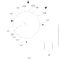
- the diverter valve assembly 10 when the diverter valve 12 rotates to a position shown in FIG. 2 , the diverter valve assembly 10 is in a first mode.
- the first baffle 121 opens the first water outlet 114 as the diverter valve 12 rotates.
- the two second baffles 123 spaced apart from each other are offset from the two second water outlets (i.e., a second water outlet 115a and a second water outlet 115b) as the diverter valve 12 rotates, so that the second water outlet 115a and the second water outlet 115b are in an open state.
- the water inlet 112 and the first water outlet 114 are located on a side where the first water diversion chamber 1111 is located, while the water return port 113 and the two second water outlets are located on a side where the second water diversion chamber 1112 is located.
- the third baffle 126 is offset from the water return port 113 as the diverter valve 12 rotates, so as to open the water return port 113.
- the first water diversion chamber 1111 is communicated with the water inlet 112 and the first water outlet 114, the first water outlet 114 is communicated with the heating device 40, and the second water diversion chamber 1112 is communicated with the two second water outlets and the water return port 113 simultaneously.
- the liquid can flow out from the first water outlet 114 via the first water diversion chamber 1111, then flow back to the second water diversion chamber 1112 through the water return port 113 after being heated by the heating device 40, and flow out from the two second water outlets.
- the flow direction of the liquid is shown by arrows in FIG. 2 . In this way, the diverter valve assembly 10 can supply water through the two second water outlets simultaneously.
- one second water outlet 115a of the two second water outlets may be communicated with the third spray arm 33, and the other second water outlet 115b may be communicated with the first spray arm 31 and second spray arm 32.
- the two second water outlets are opened simultaneously, the three spray arms of the household appliance 200 can spray heated water at the same time.
- the diverter valve assembly 10 is in the above first mode.
- the first water diversion chamber 1111 is communicated with the water inlet 112 and the first water outlet 114 through the water through hole 1211 in the first baffle 121, and the first water outlet 114 can be communicated with the heating device 40.
- the two second baffles 123 spaced apart from each other correspondingly open the two second water outlets 115 spaced apart from each other, as the diverter valve 12 rotates.
- the second water diversion chamber 1112 is communicated with the two second water outlets 115 and the water return port 113 simultaneously.
- the flow direction of the liquid in the diverter valve assembly 10 is shown by dotted arrows in FIGS. 10 and 11 .
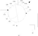
- the diverter valve assembly 10 when the diverter valve 12 rotates to a position shown in FIG. 3 , the diverter valve assembly 10 is in a second mode.
- the first baffle 121 opens the first water outlet 114 as the diverter valve 12 rotates.
- the first water diversion chamber 1111 is communicated with the water inlet 112 and the first water outlet 114, and the first water outlet 114 is communicated with the heating device 40.
- the third baffle 126 is offset from the water return port 113 as the diverter valve 12 rotates, and blocks the second water outlet 115b of the two second water outlets.
- the two second baffles 123 are both offset from the second water outlet 115a of the two second water outlets.
- the second water outlet 115a is communicated with the water return port 113, and the second water outlet 115b is blocked from the water return port 113.
- the second water diversion chamber 1112 is communicated with the second water outlet 115a and the water return port 113.
- the water inlet 112 and the first water outlet 114 are located on a side where the first water diversion chamber 1111 is located, while the water return port 113 and the two second water outlets are located on a side where the second water diversion chamber 1112 is located.
- the liquid can flow out from the first water outlet 114 via the first water diversion chamber 1111, then flow back to the second water diversion chamber 1112 through the water return port 113 after being heated by the heating device 40, and flow out from the second water outlet 115a.
- the flow direction of the liquid is shown by arrows in FIG. 3 .
- the diverter valve assembly 10 is in a mode of supplying water through one second water outlet 115a alone.
- the second water outlet 115a may be communicated with the third spray arm 33
- the second water outlet 115b may be communicated with the first spray arm 31 and the second spray arm 32.
- the diverter valve assembly 10 is in the above second mode.
- the first water diversion chamber 1111 is communicated with the water inlet 112 and the first water outlet 114 by means of the water through hole 1211 in the first baffle 121, and the first water outlet 114 can be communicated with the heating device 40.
- a second baffle 123a of the two second baffles spaced apart from each other opens the second water outlet 115a as the diverter valve 12 rotates, and a second baffle 123b of the two second baffle spaced apart from each other closes the second water outlet 115b as the diverter valve 12 rotates.
- the second water outlet 115b is blocked from the water return port 113.
- the second water diversion chamber 1112 is communicated with the second water outlet 115a and the water return port 113.
- the flow direction of liquid in the diverter valve assembly 10 is shown by dotted arrows in FIGS. 12 and 13 .
- the diverter valve assembly 10 is in a third mode.
- the first baffle 121 opens the first water outlet 114 as the diverter valve 12 rotates.
- the first water diversion chamber 1111 is communicated with the water inlet 112 and the first water outlet 114, and the first water outlet 114 is communicated with the heating device 40.
- the third baffle 126 rotates to be offset from the water return port 113, so as to open the water return port 113.
- the second baffle 123b of the two second baffles blocks the second water outlet 115a of the two second water outlets, as the diverter valve 12 rotates.
- the second water outlet 115a is blocked from the water return port 113.
- the second baffle 123a and the second baffle 123b are both offset from the second water outlet 115b, so as to open the second water outlet 115b.
- the second water outlet 115b is communicated with the water return port 113.
- the second water diversion chamber 1112 is communicated with the second water outlet 115b and the water return port 113.
- the water inlet 112 and the first water outlet 114 are located on a side where the first water diversion chamber 1111 is located, while the water return port 113 and the two second water outlets are located on a side where the second water diversion chamber 1112 is located.
- the liquid can flow out from the first water outlet 114 via the first water diversion chamber 1111, then flow back to the second water diversion chamber 1112 through the water return port 113 after being heated by the heating device 40, and flow out from the second water outlet 115b.
- the flow direction of the liquid is shown by arrows in FIG. 4 .
- the diverter valve assembly 10 is in a mode of supplying water through one second water outlet 115b alone.
- the diverter valve assembly 10 is in the above third mode.
- the first water diversion chamber 1111 is communicated with the water inlet 112 and the first water outlet 114 by means of the water through hole 1211 in the first baffle 121, and the first water outlet 114 can be communicated with the heating device 40.
- the second baffle 123a of the two second baffles spaced apart from each other closes the second water outlet 115a as the diverter valve 12 rotates, and the second baffle 123b of the two second baffle spaced apart from each other opens the second water outlet 115b as the diverter valve 12 rotates.
- the second water outlet 115a is blocked from the water return port 113, and the second water outlet 115b is in communication with the water return port 113.
- the second water diversion chamber 1112 is communicated with the second water outlet 115b and the water return port 113.
- the flow direction of liquid in the diverter valve assembly 10 is shown by dotted arrows in FIGS. 14 and 15 .
- the diverter valve assembly 10 when the diverter valve 12 rotates to a position shown in FIG. 5 , the diverter valve assembly 10 is in a fourth mode.
- the diverter valve assembly 10 rotates so that the third baffle 126 blocks the water return port 113, and the partition baffle 122 blocks the water inlet 112 and the first water outlet 114.
- the first water outlet 114 and the water return port 113 are both blocked by the partition baffle 122 from the water inlet 112, such that a flow path between the water inlet 112 with the first water outlet 114 and the heating device 40 is blocked.
- the two second baffles 123 are offset from the two second water outlets 115, to communicate the first water diversion chamber 1111 with the water inlet 112 and the two second water outlets 115.
- the water inlet 112 and the two second water outlets 115 are located on a side where the first water diversion chamber 1111 is located, and the water return port 113 and the first water outlet 114 are located on a side where the second water diversion chamber 1112 is located.
- the liquid may directly flow out from the two second water outlets 115 via the first water diversion chamber 1111, and will not be heated by the heating device 40.
- the flow direction of the liquid is shown by arrows in FIG. 5 .
- the diverter valve assembly 10 can also supply water through the two second water outlets 115 simultaneously.
- one of the two second water outlets 115 can be communicated with the third spray arm 33, and the other one of the two second water outlets 115 can be communicated with the first spray arm 31 and the second spray arm 32; the heating device 40 is bypassed; and the water entering from the water inlet 112 can be directly discharged from the second water outlets 115 without passing through the water return port 113.
- the three spray arms of the household appliance 200 can simultaneously spray water that is not heated by the heating device 40, effectively reducing the flow resistance in the dishwasher during the non-heating period, so as to further reduce the energy consumption of the dishwasher.
- the diverter valve assembly 10 is in the fourth mode.
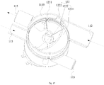
- the diverter valve 12 rotates, so that the water through hole 1211 in the first baffle 121 is not in communication with the water inlet 112 and the first water outlet 114, the partition baffle 122 blocks the water inlet 112 from the first water outlet 114, and the first water outlet 114 and the water return port 113 are both blocked by the partition baffle 122 from the water inlet 112.
- the two second baffles 123 spaced apart from each other are offset from the two second water outlets 115, so that the first water diversion chamber 1111 is communicated with the water inlet 112 and the two second water outlets 115.
- the first water diversion chamber 1111 is communicated with the water inlet 112 and the two second water outlets 115.
- the flow of the liquid in the diverter valve assembly 10 is shown by dotted arrows in FIGS. 16 to 17 .
- the diverter valve assembly 10 When the diverter valve 12 rotates to a position shown in FIG. 6 , the diverter valve assembly 10 is in a fifth mode.
- the diverter valve assembly 10 rotates, so that the first baffle 121 closes the first water outlet 114, and the partition baffle 122 blocks the water inlet 112 from the first water outlet 114, thereby blocking the flow path between the water inlet 112 with the first water outlet 114 and the heating device 40.
- the second baffle 123b of the two second baffles blocks the second water outlet 115b of the two second water outlets, and the first baffle 123a and the second baffle 123b are both offset from the second water outlet 115a of the two second water outlets, such that the first water diversion chamber 1111 is communicated with the water inlet 112 and the second water outlet 115a.
- the second water outlet 115b is blocked by the second baffle 123b from the water inlet 112. Due to the partition baffle 122, the first water outlet 114 and the water return port 113 are located on a side of the low-pressure second water diversion chamber 1112, and the water inlet 112 and the two second water outlets are located on a side of the high-pressure first water diversion chamber 1111. In this way, the flow path between the water inlet 112 with the first water outlet 114 and the heating device 40 can be completely blocked.
- the liquid can directly flow out from the second water outlet 115b via the first water diversion chamber 1111, and will not be heated by the heating device 40.
- the flow direction of the liquid is shown by arrows in FIG. 6 .
- the diverter valve assembly 10 is in a mode of supplying water through one second water outlet 115b alone.
- the second water outlet 115a can be communicated with the third spray arm 33, and the second water outlet 115b can be communicated with the first spray arm 31 and the second spray arm 32; the heating device 40 is bypassed; the water entering from the water inlet 112 can be directly discharged from the second water outlet 115a without passing through the water return port 113.
- the first spray arm 31, the second spray arm 32, and the third spray arm 33 of the household appliance 200 can alternately spray water that is not heated by the heating device 40, effectively reducing the flow resistance in the dishwasher during the non-heating period, so as to further reduce the energy consumption of the dishwasher.
- the diverter valve assembly 10 is in the above fifth mode.
- the diverter valve 12 rotates, so that the water through hole 1211 in the first baffle 121 is not in communication with the water inlet 112 and the first water outlet 114, the partition baffle 122 blocks the water inlet 112 from the first water outlet 114, and the first water outlet 114 and the water return port 113 are both blocked by the partition baffle 122 from the water inlet 112.
- the second baffle 123b of the two second baffles spaced apart from each other closes the second water outlet 115b of the two second water outlets, to block the second water outlet 115b from the first water diversion chamber 1111; the second baffle 123a of the two second baffles opens the second water outlet 115a of the two second water outlets, to communicate the second water outlet 115a with the first water diversion chamber 1111 and the water inlet 112.
- the flow of the liquid in the diverter valve assembly 10 is shown by dotted arrows in FIGS. 18 to 19 .
- the diverter valve assembly 10 When the diverter valve 12 rotates to a position shown in FIG. 7 , the diverter valve assembly 10 is in a sixth mode.
- the diverter valve assembly 10 rotates, so that the first baffle 121 closes the first water outlet 114, the partition baffle 122 blocks the water inlet 112 from the first water outlet 114, and hence the flow path between the water inlet 112 with the first water outlet 114 and the heating device 40 is blocked.
- the second baffle 123a of the two second baffles blocks the second water outlet 115a of the two second water outlets.
- the first baffle 123a and the second baffle 123b are both offset from the second water outlet 115b of the two second water outlets, such that the first water diversion chamber 1111 is communicated with the water inlet 112 and the second water outlet 115b.
- the second water outlet 115a is blocked by the second baffle 123a from the water inlet 112. Since the first baffle 121 blocks the first water outlet 114, even if the water return port 113 is on the side of the high-pressure first water diversion chamber 111, the liquid flowing out from the water inlet 112 will not pass through the heating device 40.
- the liquid can directly flow out from the second water outlet 115a via the first water diversion chamber 1111, and will not be heated by the heating device 40.
- the flow direction of the liquid is shown by arrows in FIG. 7 .
- the diverter valve assembly 10 is in a mode of supplying water through one second water outlet 115a alone.
- the diverter valve assembly 10 can also realize the switching of seven different modes.
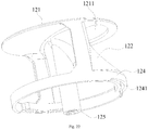
- the diverter valve 12 includes the fixing portion 124.
- the second baffle 123 is detachably mounted to the fixing portion 124, which facilitates the mounting and detachment of the second baffle 123.
- the partition baffle 122 is fixedly connected to the fixing portion 124.
- the partition baffle 122 and the fixing portion 124 are of an integral structure.
- the partition baffle 122 and the second baffle 123 are located on both sides of the fixing portion 124.
- the second baffle 123 rotates along with the fixing portion 124 to open or close the second water outlet 115. In an example shown in FIG.
- the second baffle 123 can be pressurized to seal the second water outlet 115.
- the second baffle plate can seal the second water outlet under the action of gravity, and can be pressurized to open the second water outlet.
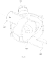
- the housing 11 is provided with a channel 13 (see FIG. 11 ).
- the channel 13 is communicated with the second water outlet 115.
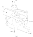
- the second baffle 123 includes a bottom plate 1231 and a first fitting portion 1232 extending upwards from the bottom plate 1231 (see FIG. 21 ).
- the fixing portion 124 is formed with a second fitting portion 1241 that is fitted with the first fitting portion 1232.
- the second baffle 123 can open or close an entry 131 of the channel 13 through the bottom plate 1231 when the diverter valve 12 rotates, so as to open or close the second water outlet 115.
- the first fitting portion 1232 is a tab extending upwards from the bottom plate 1231.
- the second fitting portion 1241 is a through slot formed in a side portion of the fixing portion 124.
- the tab can pass through the through slot, so that the first fitting portion 1232 is detachably mounted to the second fitting portion 1241. Moreover, the tab can move up and down in the through slot.
- the diverter valve 12 has a substantially cylindrical shape overall.
- the fixing portion 124 exhibits a ring shape.
- Two second baffles 123 are provided.
- the two second baffles 123 are mounted to the fixing portion 124 and spaced apart from each other, and can move in the circumferential direction of the water diversion chamber 111 along with the fixing portion 124.
- the bottom plate 1231 has a substantially fan shape.
- a sealing surface 1233 is formed on a side of the bottom plate 1231 away from the first fitting portion 1232. Under the action of water pressure, the bottom plate 1231 is pressurized, and the entry 131 of the channel 13 can be sealed by the sealing surface 1233, such that the second water outlet 115 is sealed.
- the diverter valve assembly 10 includes a driving mechanism 14.
- the driving mechanism 14 is connected to the diverter valve 12.
- the driving mechanism is used to drive the diverter valve 12 to rotate.
- the driving mechanism 14 includes a driving portion 141 and a transmission portion 15.
- the transmission portion 15 connects the driving portion 141 and the diverter valve 12.
- the driving portion 141 is used to drive the transmission portion 15 to rotate, so as to drive the diverter valve 12 to rotate.
- the transmission portion 15 can be configured according to specific situations, and for example, a gear meshing transmission manner, a belt transmission manner, or a coupler transmission manner may be adopted.
- the diverter valve assembly 10 includes a sensor 16.
- the transmission portion 15 includes a transmission member 151, and the sensor 16 is used to detect a position of the transmission member 151.
- a rotation state of the diverter valve 12 can be determined according to the position of the transmission member 151 detected by the sensor 16, and then the rotation of the diverter valve 12 can be controlled by means of the transmission member 151, so that the switching among different communication states of the diverter valve assembly 10 can be realized accurately by controlling the rotation of the diverter valve 12.
- the transmission member 151 may be a transmission gear, for example.
- the driving portion 141 includes an electric motor 142.
- the diverter valve 12 includes a driving rod 125.
- the driving rod 125 extends downwards from the top of the diverter valve 12.
- the diverter valve 12 is connected to the transmission member 151 through the driving rod 125.
- the driving rod 125 extends downwards from the partition baffle 122.
- the fixing portion 124 surrounds the driving rod 125.
- the diverter valve 12 is connected to the transmission member 151 through the driving rod 125.
- the driving rod 125 may be connected to the transmission member 151 in a snapping manner.
- the electric motor 142 is used to drive the transmission member 151 to rotate, so as to drive the driving rod 125 to rotate.
- the first baffle 121, the driving rod 125, the partition baffle 122, and the fixing portion 124 are of an integral structure, which is convenient for processing and enhances the overall stability of the diverter valve 12.
- a fixing cover plate 19 may be provided, the electric motor 142 and the transmission member 151 are disposed on opposite sides of the fixing cover plate 19, and a rotating shaft of the electric motor 142 passes through the fixing cover plate 19 and is connected to the transmission member 151.
- the housing 11 includes a lower housing 17 and an upper housing 18.
- the lower housing 17 is connected to the upper housing 18.
- the connection manner of the lower housing 17 and the upper housing 18 can be set according to specific situations.
- the lower housing 17 is provided with the water inlet 112, the water return port 113 and the second water outlet 115; the upper housing 18 is provided with the first water outlet 114.
- the lower housing 17 defines the water diversion chamber 111 therein. An upper end of the water diversion chamber 111 is open.
- the lower housing 17 is provided with the water inlet 112, the water return port 113, and the second water outlet 115.
- the upper housing 18 is disposed on an upper end of the lower housing 17 and closes the water diversion chamber 111.
- the upper housing 18 is provided with the first water outlet 114.
- the upper housing 18 can be detachably mounted on the upper end of the lower housing 17, and the water inlet 112, the water return port 113 and the second water outlet 115 can be provided in a side wall or a bottom wall or a top wall of the lower housing 11, which can be set according to specific situations.
- the lower housing 17 is substantially columnar.
- the side wall of the lower housing 17 is formed with a water inlet pipe 171 and a water return pipe 172.
- the top wall of the lower housing 17 is formed with a first water outlet pipe 173.
- the bottom wall of the lower housing 17 is formed with a second water outlet pipe 174.
- the water inlet pipe 171 and the water return pipe 172 extend outwards from the side wall of the lower housing 17.
- the first water outlet pipe 173 extends outwards from the top wall of the lower housing 17.
- the second water outlet pipe 174 extends outwards from the bottom wall of the lower housing 17.
- the water inlet pipe 171 is provided with the water inlet 112.
- the water return pipe 172 is provided with the water return port 113.
- the first water outlet pipe 173 is provided with the first water outlet 114.
- the second water outlet pipe 174 is provided with the second water outlet 115.
- the dishwasher 100 includes: a washing inner container 1, a spray arm, a heating device 3, and a diverter valve 4.
- the washing inner container 1 is provided with a washing outlet 111.
- the spray arm is disposed in the washing inner container 1, and the spray arm is provided with a spray inlet.
- the heating device 3 has a to-be-heated water inlet 321 and a heated water outlet 322, and the heating device 3 is used to heat washing water.
- the diverter valve 4 is provided with a water inlet 41, a second water outlet, a first water outlet 43, and a water return port 44.
- the water inlet 41 is connected to the washing outlet 111.
- the second water outlet is connected to the spray inlet.
- the first water outlet 43 is connected to the to-be-heated water inlet 321.
- the water return port 44 is connected to the heated water outlet 322.
- the washing inner container 1 defines a washing chamber therein.
- a bracket may be provided in the washing chamber and used to support tableware.
- the spray arm is disposed in the washing inner container 1 and is provided with the spray inlet. The washing water enters the spray arm through the spray inlet, and then is sprayed to the tableware through a nozzle provided in the spray arm, thereby cleaning the tableware.
- the washing water sprayed on the tableware may be collected in a water sump 11 at the bottom of the washing inner container 1, and the washing outlet 111 is formed in the bottom of the water sump 11, such that the washing water flows out from the washing outlet 111.
- a washing water circulation system further includes a washing pump 5.
- the washing pump 5 has an inlet in communication with the washing outlet 111 and an outlet in communication with the spray inlet, and the washing pump 5 offers power to the circulation of the washing water.
- the dishwasher 100 includes at least two working modes. In a first mode, the water inlet 41 of the diverter valve 4 is communicated with the second water outlet. In a second mode, the water inlet 41 of the diverter valve 4 is communicated with the first water outlet 43, and the water return port 44 is communicated with the second water outlet.
- the washing water when the water inlet 41 of the diverter valve 4 is communicated with the second water outlet, under the drive of the washing pump 5, the washing water flows out from the washing outlet 111, then flows towards the spray inlet via the water inlet 41 and the second water outlet in sequence, and flows into the spray arm from the spray inlet to be sprayed.
- the first mode may be called a non-heating mode.
- the heating device 3 can be turned off, thereby saving energy.
- the heating device may also be turned on as needed, and be used to heat other apparatuses, spaces, or the like.
- the heating device can be turned on to dry the inner space of the washing inner container 1.
- the washing water flows out from the washing outlet 111, then flows towards the to-be-heated water inlet 321 of the heating device 3 via the water inlet 41 and the first water outlet 43 in sequence, and flows into the heating device 3 from the to-be-heated water inlet 321.
- the washing water is heated to high-temperature washing water, then flows out from the heated water outlet 322, and flows towards the spray inlet via the water return port 44 and the second water outlet in sequence.
- the high-temperature washing water flows into the spray arm from the spray inlet to be sprayed.
- the washing water flows through the heating device 3, and at this time, the heating device 3 can be started to heat the washing water to increase the temperature of the washing water, so that the dishwasher 100 operates in a high-temperature washing mode, which can improve the washing effect.
- the second mode may be called a heating mode.
- the washing water can be diverted in different washing modes.
- the non-heating mode the washing water does not flow through the heating device 3, which can reduce the flow resistance in the water flow system during the non-heating period to a certain extent, speed up the water flow, improve the cleaning speed and cleanliness, and upgrade the system washing performance.
- the turn-on or turn-off of the heating device 3 and the flow path of the washing water can be independently controlled, so that the use of the dishwasher 100 becomes more convenient.
- the water diversion function is integrated in one diverter valve 4, so that the water diversion structure is compact, the pipeline is shortened, and the control method is simple.
- the heating device 3 includes a compressor 31, a condenser 32, a throttling device 33, and an evaporator 34 that are sequentially connected end to end, so as to constitute a refrigerant cycle.
- the dishwasher 100 is a heat pump dishwasher, and a refrigerant undergoes processes of compression, condensation and heat release, throttling expansion, evaporation and heat absorption in a heat pump system. After converting low-grade energy into high-grade thermal energy, the refrigerant is released into the washing water to achieve a purpose of efficient heating with low energy consumption.
- the performance coefficient of the heating system using the heat pump is three to four times or even more times higher than the conventional electric heating technology.
- the dishwasher 100 adopting the heat pump heating technology has a significant energy saving effect and can greatly reduce the energy consumption, which is an effective means to reduce the energy consumption of the dishwasher 100.
- the condenser 32 defines a first liquid flow channel and a second liquid flow channel therein. Two ends of the first liquid flow channel are provided with the to-be-heated water inlet 321 and the heated water outlet 322, respectively. Two ends of the second liquid flow channel are communicated with the compressor 31 and the throttling device 33, respectively.
- the condenser 32 is a liquid-to-liquid heat exchanger, thereby improving the heating efficiency of condensate water.
- the first liquid flow channel and the second liquid flow channel may be designed complicatedly, to increase the flow resistance in the first liquid flow channel.
- the condenser 32 is directly connected to the original washing system flow path, there may be problems that the spray pressure of the spray arm of the dishwasher 100 drops or the power consumption of the washing pump 5 increases, especially during the non-heating period.
- the diverter valve 4 by providing the diverter valve 4, the problem of large flow resistance caused by the washing water flowing through the condenser 32 during the non-heating period can be solved.
- the above heat pump system is turned on, and the washing water flowing out of the washing inner container 1 can be heated by the condenser, and the high-temperature washing water enters the spray arm to wash the tableware in the washing inner container 1 at high temperature, thereby improving the washing effect.
- the above heat pump system can be turned off, which can save energy.
- the above heat pump system can also be turned on as needed and be used to heat or cool other apparatuses, spaces, or the like.
- the heat pump system can be turned on, to utilize the condenser 32 to heat and dry the inner space of the washing inner container 1 or utilize the evaporator 34 to cool and dehumidify the inner space of the washing inner container 1.
- the heating device 3 may also adopt electric heating.
- electric heating wires or the thick film heating technology may be used to heat the circulating water. Electric heating is used to heat the washing water, the structure is simple, and the control is simple.
- the heating device 3 will be exemplified as a heat pump system below for detailed description.
- each spray arm there may be a plurality of spray arms and one second water outlet.
- the spray inlet of each spray arm is communicated with the second water outlet, so that the washing water can be dispersed into the plurality of spray arms to be sprayed, after flowing out from the second water outlet, and hence the cleaning effect is better.
- each second water outlet is communicated with the spray inlet of at least one spray arm.
- the plurality of second water outlets and the plurality of spray arms can be combined in various ways, thereby realizing connection structures for different requirements, and achieving alternate cleaning of the spray arms.
- each second water outlet is communicated with the spray inlet of at least one spray arm.
- the water inlet 41 is selectively communicated with at least one second water outlet, so that in the non-heating mode, the washing water can flow into one or more spray arms as needed, thereby achieving the alternate cleaning mode.
- each second water outlet is communicated with the spray inlet of at least one spray arm.
- the water return port 44 is selectively communicated with at least one second water outlet, so that in the heating mode, the washing water can flow into one or more spray arms as needed, thereby achieving the alternate cleaning mode.
- the number of spray arms and the number of second water outlets may be equal or unequal, so that the spray arms and second water outlets can be combined as needed. Therefore, in different modes, the washing water can enter a corresponding spray arm through the second water outlet for spray cleaning.
- the cleaning mode is diversified, and the use of the dishwasher 100 becomes more convenient.
- the connection manner of the spray arm and the second water outlet, as well as the control of the diverter valve in the case of the corresponding connection manner of the spray arm and the second water outlet will be described below with reference to FIGS. 23-28 .
- dishwasher 100 according to an embodiment of the present disclosure will be described below with reference to FIGS. 23-28 .
- the spray arm includes: a lower spray arm 23, an upper spray arm 21, and a middle spray arm 22.
- the lower spray arm 23 is disposed at a lower part inside the washing inner container 1
- the upper spray arm 21 is disposed at an upper part inside the washing inner container 1
- the middle spray arm 22 is disposed at a middle part inside the washing inner container 1.
- each second water outlet is connected to at least one spray arm.
- one of the second water outlets is connected to the lower spray arm 23, and the other one thereof is connected to the upper spray arm 21 and the middle spray arm 22 at the same time.
- the water inlet 41 is communicated with one of the second water outlets, or the water inlet 41 is communicated with the other one of the second water outlets, or the water inlet 41 is simultaneously communicated with both of the second water outlets. Therefore, in the first mode, when the water inlet 41 is communicated with one of the second water outlets, the washing water can enter the corresponding spray arm through this second water outlet; when the water inlet 41 is communicated with the other one of the second water outlets, the washing water can enter the other corresponding spray arm through the other second water outlet; when the water inlet 41 is simultaneously communicated with both of the second water outlets, the washing water can enter all the spray arms. Therefore, according to different needs, by communicating the water inlet 41 with different second water outlets, alternate cleaning in the non-heating mode can be realized.
- the non-heating mode the washing water does not flow through the heating device 3 (the condenser 32), and the alternate cleaning sequence is solved in the diverter valve 4, and three non-heating modes are realized: the upper spray arm 21 and the middle spray arm 22 work; the lower spray arm 23 works; the upper spray arm 21, the middle spray arm 22, and the lower spray arm 23 work simultaneously. Therefore, in the non-heating mode, the loss due to the flow resistance caused by flowing through the heating device 3 (the condenser 32) in the washing cycle can be avoided, and hence the pressure of the spray arms and the washing effect will not be affected.
- the water return port 44 is communicated with one of the second water outlets, or the water inlet 41 is communicated with the other one of the second water outlets, or the water inlet 41 is simultaneously communicated with both of the second water outlets. Therefore, in the second mode, when the water return port 44 is communicated with one of the second water outlets, the high-temperature washing water can enter the corresponding spray arm through this second water outlet; when the water return port 44 is communicated with the other one of the second water outlets, the high-temperature washing water can enter the other corresponding spray arm through the other second water outlet; when the water return port 44 is simultaneously communicated with both of the second water outlets, the high-temperature washing water can enter all the spray arms. Therefore, according to different needs, by communicating the water return port 44 with different second water outlets, alternate cleaning in the heating mode can be realized.
- the washing water flows through the heating device 3 (the condenser 32), and the flow path is switched in the diverter valve 4.
- the circulating washing water flows back to the diverter valve 4 after being heated by the heating device 3 (the condenser 32), and three heating modes are realized: the upper spray arm 21 and the middle spray arm 22 work; the lower spray arm 23 works; the upper spray arm 21, the middle spray arm 22, and the lower spray arm 23 work simultaneously. Therefore, it is possible to achieve alternate washing during the entire time sequence in the heating process.
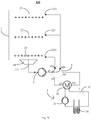
- the dishwasher 100 includes: a washing inner container 1, a washing pump 5, an upper spray arm 21, a middle spray arm 22, a lower spray arm 23, a heating device 3, and a diverter valve 4.
- a water sump 11 is provided in a bottom wall of the washing inner container 1.
- the heating device 3 includes a compressor 31, a throttling device 33, a condenser 32, and an evaporator 34. Further, the compressor 31, the condenser 32, the throttling device 33, and the evaporator 34 are sequentially connected through pipelines and constitute a closed circulation system, and a refrigerant circulates in the closed pipeline system.
- the diverter valve 4 may include a valve body casing, a valve sheet, an electric motor, and a valve sheet transmission mechanism.
- the valve body casing is provided with a water inlet 41, a second water outlet, a first water outlet 43, and a water return port 44.
- Two second water outlets are provided, that is, a second water outlet 42a located on the left and a second water outlet 42b located on the right in FIGS. 23-28 .
- washing pump 5 is connected by a pipeline, and the washing pump 5 has an inlet in communication with the water sump 11 and an outlet in communication with the water inlet 41 of the diverter valve 4.
- the upper spray arm 21 and the middle spray arm 22 are disposed in the inner container, and spray inlets of the two spray arms converge into one path.
- a spray inlet 211 of the upper spray arm 21 and a spray inlet 221 of the middle spray arm 22 are connected by a pipeline, and then communicated with the second water outlet of the diverter valve 4 (for example, the second water outlet 42b on the right in FIGS. 23-28 ).
- the lower spray arm 23 is disposed in the inner container, and a spray inlet 231 of the lower spray arm 23 is communicated with the other second water outlet (for example, the second water outlet 42a on the left in FIGS. 23-28 ) of the diverter valve 4 through pipeline connection.
- the other second water outlet for example, the second water outlet 42a on the left in FIGS. 23-28
- a to-be-heated water inlet 321 of the condenser 32 of the heating device 3 is communicated with the first water outlet 43 of the diverter valve 4 through a pipeline, and a heated water outlet 322 is communicated with the water return port 44 of the diverter valve 4 through a pipeline.
- the washing pump 5 can continuously circulate the washing water in the water sump 11 to the condenser 32 and various spray arms, so as to achieve the purpose of washing the tableware.
- a rotation angle of the valve sheet of the diverter valve 4 can be controlled to realize the following six modes.
- valve sheet communicates the water inlet 41 with the second water outlet 42a on the left, and blocks the first water outlet 43, the water return port 44, and the second water outlet 42b on the right, clean water delivered by the washing pump 5 is directly sent to the lower spray arm 23, so that the dishwasher 100 realizes a spray cleaning mode of the lower spray arm 23 in a non-heating situation.
- valve sheet communicates the water inlet 41 with the second water outlet 42b on the right, and blocks the first water outlet 43, the water return port 44, and the second water outlet 42a on the left, clean water delivered by the washing pump 5 is sent to the upper spray arm 21 and the middle spray arm 22 simultaneously, so that the dishwasher 100 realizes a simultaneous spray cleaning mode of the upper spray arm 21 and the middle spray arm 22 in a non-heating situation.
- valve sheet communicates the water inlet 41 with the second water outlet 42a on the left and the second water outlet 42b on the right, and blocks the first water outlet 43 and the water return port 44, clean water delivered by the washing pump 5 is sent to the upper spray arm 21, the middle spray arm 22, and the lower spray arm 23 simultaneously, so that the dishwasher 100 realizes a simultaneous spray cleaning mode of the upper spray arm 21, the middle spray arm 22, and the lower spray arm 23 in a non-heating situation.
- valve sheet communicates the water inlet 41 with the water return port 44
- the dishwasher 100 enters a heating mode of the condenser 32. In such a case, communication channels of the water inlet 41 and the water return port 44 are blocked from communication channels of other interfaces.
- the valve sheet in a heating mode, communicates the water inlet 41 with the first water outlet 43 and communicates the water return port 44 with the second water outlet 42a on the left, and blocks the second water outlet 42b on the right, so that the dishwasher 100 can realize a spray cleaning mode of the lower spray arm 23 in the heating situation.
- the valve sheet in a heating mode, communicates the water inlet 41 with the first water outlet 43 and communicates the water return port 44 with the second water outlet 42b on the right, and blocks the second water outlet 42a on the left, so that the dishwasher 100 can realize a spray cleaning mode of the lower spray arm 23, the upper spray arm 21, and the middle spray arm 22 in the heating situation.
- the valve sheet in a heating mode, communicates the water inlet 41 with the first water outlet 43, and communicates the water return port 44 with the second water outlet 42a on the left and the second water outlet 42b on the right, so that the dishwasher 100 can realize a simultaneous spray cleaning mode of the upper spray arm 21, the middle spray arm 22, and the lower spray arm 23 in the heating situation.
- the dishwasher 100 during the non-heating period, the water does not flow through the heating device 3 (the condenser 32), which can reduce the resistance pressure drop in the water flow system during the non-heating period and improve the washing performance of the system.
- the dishwasher 100 can still adopt the cleaning mode that different spray arms spray alternately, which can reduce the water consumption of the system effectively.
- the water diversion function is completely integrated in one diverter valve 4 in the system, such that the structure is compact, the pipeline is shortened, and the control method is simple.
- the dishwasher 100 includes an upper spray arm 21, a middle spray arm 22, and a lower spray arm 23.
- a spray inlet 211 of the upper spray arm 21 and a spray inlet 221 of the middle spray arm 22 do not merge.
- Three second water outlets are provided and connected to a spray inlet 231 of the lower spray arm 23, the spray inlet 211 of the upper spray arm 21, and the spray inlet 221 of the middle spray arm 22, respectively.
- the diverter valve 4 can realize a six-way six-path mode, and achieve seven alternate cleaning modes in the non-heating mode: a spray cleaning mode of the lower spray arm 23; a spray cleaning mode of the middle spray arm 22; a spray cleaning mode of the lower spray arm 23; a simultaneous spray cleaning mode of the upper spray arm 21 and the middle spray arm 22; a simultaneous spray cleaning mode of the upper spray arm 21 and the lower spray arm 23; a simultaneous spray cleaning mode of the lower spray arm 23 and the middle spray arm 22; a simultaneous spray cleaning mode of the upper spray arm 21, the middle spray arm 22 and the lower spray arm 23.
- the above seven alternate cleaning modes can also be realized. As a result, in this embodiment, there are fourteen alternate cleaning modes in total.
- the structure of the diverter valve 4 in this embodiment is more complicated, but the above technical effects can still be achieved. That is, during the non-heating period, the water does not flow through the heating device 3 (the condenser 32), which can reduce the resistance pressure drop in the water flow system during the non-heating period and improve the washing performance of the system. During the heating period, the dishwasher 100 can still adopt the cleaning mode that different spray arms spray alternately, which can reduce the water consumption of the system effectively.
- the water diversion function is completely integrated in one diverter valve 4 in the system, such that the structure is compact, the pipeline is shortened, and the control method is simple.
- the dishwasher 100 includes an upper spray arm 21, a middle spray arm 22, and a lower spray arm 23.
- the diverter valve 4 is provided with one second water outlet.
- a spray inlet 211 of the upper spray arm 21, a spray inlet 221 of the middle spray arm 22, and a spray inlet 231 of the lower spray arm 23 merge into the second water outlet of the diverter valve 4.
- the diverter valve 4 adopts a six-way six-path form, so that a cleaning mode that the upper spray arm 21, the middle spray arm 22, and the lower spray arm 23 simultaneously spray in the heating situation can be achieved, and a cleaning mode that the upper spray arm 21, the middle spray arm 22, and the lower spray arm 23 simultaneously spray in the non-heating situation can be achieved.
- the design of the diverter valve 4 will be further simplified, which can achieve the purpose of reducing the resistance pressure drop in the water flow system during the non-heating period.
- the dishwasher 100 includes any two of an upper spray arm 21, a middle spray arm 22, and a lower spray arm 23. There are two second water outlets, and the two second water outlets are connected to two spray arms correspondingly. Hence, a cleaning mode that the two spray arms alternately spray in heating and non-heating modes can be realized.
- the washing inner container 1 of the dishwasher 100 may be provided with the lower spray arm 23 and the middle spray arm 22, and the upper spray arm 21 is not provided.
- Two second water outlets are provided, one of the two second water outlets is connected to a spray inlet 231 of the lower spray arm 23, and the other one thereof is connected to a spray inlet 221 of the middle spray arm 22.
- three alternate cleaning modes in the non-heating mode can be realized: a spray cleaning mode of the upper spray arm 21; a spray cleaning mode of the middle spray arm 22; a simultaneous spray cleaning mode of the upper spray arm 21 and the middle spray arm 22.
- the above three alternate cleaning modes can also be realized.
- the dishwasher 100 includes any two of an upper spray arm 21, a middle spray arm 22, and a lower spray arm 23. There is one second water outlet, and the two spray arms are both connected to the second water outlet, so that a spray cleaning mode of double spray arms in the heating mode and the non-heating mode can be realized.
- there are two washing modes in total namely a heating double spray arm washing mode, and a non-heating double spray arm washing mode.
- the washing inner container 1 may be provided with only one of a lower spray arm 23, a middle spray arm 22, and an upper spray arm 21.
- there are two washing modes in total namely a heating single spray arm washing mode, and a non-heating single spray arm washing mode.
- the washing water can be diverted in different washing modes.
- the non-heating mode the washing water does not flow through the heating device 3, which can reduce the flow resistance in the water flow system during the non-heating period to a certain extent, speed up the water flow, improve the cleaning speed and cleanliness, and upgrade the system washing performance.
- the turn-on or turn-off of the heating device 3 and the flow path of the washing water can be independently controlled, so that the use of the dishwasher 100 becomes more convenient.
- the water diversion function is integrated in one diverter valve 4, so that the water diversion structure is compact, the pipeline is shortened, and the control method is simple.
- a structure in which a first feature is "on" or “below” a second feature may include an embodiment in which the first feature is in direct contact with the second feature, and may also include an embodiment in which the first feature and the second feature are not in direct contact with each other, but are contacted via an additional feature formed therebetween.
- a first feature "on,” “above,” or “on top of” a second feature may include an embodiment in which the first feature is right or obliquely “on,” “above,” or “on top of” the second feature, or just means that the first feature is at a height higher than that of the second feature; while a first feature “below,” “under,” or “on bottom of” a second feature may include an embodiment in which the first feature is right or obliquely “below,” “under,” or “on bottom of' the second feature, or just means that the first feature is at a height lower than that of the second feature.
Landscapes
- Engineering & Computer Science (AREA)
- Water Supply & Treatment (AREA)
- Multiple-Way Valves (AREA)
- Washing And Drying Of Tableware (AREA)
Abstract
Description
- This application claims priority to and benefits of Chinese Application No.
2018116024220 2018222241511 2018200808816 2018100439089 - The present disclosure relates to a technical field of household appliances, and more particularly to a diverter valve assembly, a dishwasher, and a household appliance.
- Generally, in order to improve a cleaning effect on tableware, a dishwasher may be usually provided with a heating device that heats washing water, so that high-temperature washing water can wash away contaminants on the tableware and supply heat to the tableware. Therefore, the dishwasher system can obtain a high cleaning and drying rate in a short washing time. However, due to the structural limitation of the system, when the washing water passes through the heating device, the flow resistance in the water channel is large, which may cause spray pressure of a spray arm of the dishwasher to drop or cause power consumption of a washing pump to increase. The heating process only takes part of the total washing time of the dishwasher. If the heating system is directly connected to the washing water circulation flow path, during a non-heating period, the loss due to the resistance when the water flows through the heating device may cause the spray pressure of the spray arm to decrease and the washing water flow to decrease, resulting in a poor washing effect.
- The present disclosure provides a diverter valve assembly, a dishwasher, and a household appliance.
- The diverter valve assembly according to embodiments of the present disclosure includes a housing and a diverter valve. The housing defines a water diversion chamber therein, and is provided with a water inlet, a water return port, a first water outlet, and a second water outlet. The diverter valve is disposed in the water diversion chamber and configured to partition the water diversion chamber into a first water diversion chamber and a second water diversion chamber. The first water diversion chamber is communicated with the water inlet. The diverter valve is rotatable in the water diversion chamber to communicate the first water diversion chamber with the water inlet and the first water outlet and communicate the second water diversion chamber with the second water outlet and the water return port, or to block the water inlet from the first water outlet and communicate the first water diversion chamber with the water inlet and the second water outlet.
- For the above diverter valve assembly, when the diverter valve assembly is applied to a household appliance, a heating device may be connected in a pipeline connecting the first water outlet and the water return port, and a spray arm of the household appliance may be connected to the second water outlet through a pipeline. Therefore, when water needs to be heated, the diverter valve can rotate, so that the first water diversion chamber is communicated with the water inlet and the first water outlet. In such a case, water entering through the water inlet can flow out from the first water outlet via the first water diversion chamber and be heated by the heating device, and the water heated by the heating device can flow into the second water diversion chamber from the water return port and flow to the spray arm from the second water outlet to be sprayed. When water does not need to be heated, the diverter valve can rotate, so that the water inlet is blocked from the first water outlet. In such a case, water entering through the water inlet can flow directly from the second water outlet to the spray arm via the first water diversion chamber and be sprayed. That is, the water does not pass through the heating device, which can reduce the resistance in a water flow system during a non-heating period, solve problems of huge power consumption of a washing pump and long washing time, and hence improve the system washing performance of the household appliance.
- In some embodiments, the diverter valve has a first baffle, and the first baffle can open or close the first water outlet when the diverter valve rotates.
- In some embodiments, the first baffle is provided with a water through hole, and when the diverter valve rotates, the first baffle can communicate the first water outlet with the first water diversion chamber by means of the water through hole.
- In some embodiments, the diverter valve has a partition baffle, the partition baffle partitions the water diversion chamber into a first water diversion chamber and a second water diversion chamber, and the partition baffle can rotate in the water diversion chamber to communicate the water inlet with the first water outlet or block the water inlet from the first water outlet.
- In some embodiments, the partition baffle includes a baffle body and two baffle connecting pieces connected to both sides of the baffle body, and the two baffle connecting pieces are each attached to an inner wall of the water diversion chamber.
- In some embodiments, the baffle connecting pieces are arcuately connected to the inner wall of the water diversion chamber.
- In some embodiments, the diverter valve has a second baffle, and the second baffle can open or close the second water outlet when the diverter valve rotates.
- In some embodiments, a plurality of second water outlets are provided, a plurality of second baffles are provided, and the number of the second baffles is identical to the number of the second water outlets.
- In some embodiments, two second water outlets are provided, and two second baffles are provided; the two second water outlets are spaced apart from each other, and the two second baffles are spaced apart from each other.
- In some embodiments, the diverter valve includes a fixing portion, and the second baffle is detachably mounted to the fixing portion.
- In some embodiments, the housing is provided with a channel, and the channel is communicated with the second water outlet; the second baffle includes a bottom plate and a first fitting portion extending upwards from the bottom plate; the fixing portion is formed with a second fitting portion fitted with the first fitting portion; when the diverter valve rotates, the second baffle can open or close an entry of the channel through the bottom plate to open or close the second water outlet.
- In some embodiments, the diverter valve has a third baffle, and the third baffle can open or close the water return port when the diverter valve rotates.
- In some embodiments, the diverter valve assembly includes a driving mechanism, and the driving mechanism is connected to the diverter valve and configured to drive the diverter valve to rotate.
- In some embodiments, the diverter valve assembly includes a sensor; the driving mechanism includes a driving portion and a transmission portion; the transmission portion connects the driving portion to the diverter valve and includes a transmission member; and the sensor is used to detect a position of the transmission member.
- In some embodiments, the driving portion includes an electric motor; the diverter valve includes a driving rod, and the driving rod extends downwards from a top of the diverter valve; the diverter valve is connected to the transmission member through the driving rod.
- In some embodiments, the housing includes a lower housing and an upper housing, and the lower housing is connected to the upper housing.
- In some embodiments, the lower housing is provided with the water inlet, the water return port, and the second water outlet; the upper housing is provided with the first water outlet.
- The household appliance according to embodiments of the present disclosure includes: a chamber body, a spray arm, a heating device, and the diverter valve assembly according to any one of the above embodiments. The chamber body defines a chamber therein. The spray arm is at least partially disposed in the chamber. The second water outlet is connected to the spray arm. The heating device is connected to the first water outlet and the water return port.
- In the above household appliance, when the diverter valve assembly is applied to the household appliance, the heating device may be connected in a pipeline connecting the first water outlet and the water return port, and the spray arm of the household appliance may be connected to the second water outlet through a pipeline. Therefore, when water needs to be heated, the diverter valve can rotate, so that the first water diversion chamber is communicated with the water inlet and the first water outlet. In such a case, water entering through the water inlet can flow out from the first water outlet via the first water diversion chamber and be heated by the heating device, and the water heated by the heating device can flow into the second water diversion chamber from the water return port and flow to the spray arm from the second water outlet to be sprayed. When water does not need to be heated, the diverter valve can rotate, so that the water inlet is blocked from the first water outlet. In such a case, water entering through the water inlet can flow directly from the second water outlet to the spray arm via the first water diversion chamber and be sprayed. That is, the water does not pass through the heating device, which can reduce the resistance in a water flow system during a non-heating period, solve problems of huge power consumption of a washing pump and long washing time, and hence improve the system washing performance of the household appliance.
- The dishwasher according to embodiments of the present disclosure includes: a washing inner container, a spray arm, a heating device, and a diverter valve. The washing inner container is provided with a washing outlet. The spray arm is disposed in the washing inner container and provided with a spray inlet. The heating device is configured to heat washing water, and has a to-be-heated water inlet and a heated water outlet. The diverter valve is provided with a water inlet, a second water outlet, a first water outlet, and a water return port. The water inlet is connected to the washing outlet, the second water outlet is connected to the spray inlet, the first water outlet is connected to the to-be-heated water inlet, and the water return port is connected to the heated water outlet. The dishwasher includes at least two working modes. In a first mode, the water inlet of the diverter valve is communicated with the second water outlet. In a second mode, the water inlet of the diverter valve is communicated with the first water outlet, and the water return port is communicated with the second water outlet.
- In the above dishwasher, by providing the diverter valve, the washing water does not flow through the heating device during a non-heating period, such that the water flow resistance can be reduced, the washing performance can be improved, and the system piping is simple and compact.
- In some embodiments, a plurality of spray arms are provided, and the spray inlet of each spray arm is communicated with the second water outlet.
- In some embodiments, a plurality of spray arms are provided, a plurality of second water outlets are provided, and each second water outlet is communicated with the spray inlet of at least one spray arm.
- In some embodiments, a plurality of second water outlets are provided; in the first mode, the water inlet is selectively communicated with at least one second water outlet; in the second mode, the water return port is selectively communicated with at least one second water outlet.
- In some embodiments, two second water outlets are provided. In the first mode, the water inlet is communicated with one of the second water outlets, or the water inlet is communicated with the other one of the second water outlets, or the water inlet is simultaneously communicated with both of the second water outlets. In the second mode, the water return port is communicated with one of the second water outlets, or the water inlet is communicated with the other one of the second water outlets, or the water inlet is simultaneously communicated with both of the second water outlets.
- In some embodiments, the spray arm includes: a lower spray arm provided at a lower part inside the washing inner container; an upper spray arm provided at an upper part inside the washing inner container; and a middle spray arm provided at a middle part inside the washing inner container.
- In some embodiments, two second water outlets are provided; a spray inlet of the lower spray arm is communicated with one of the second water outlets; a spray inlet of the upper spray arm and a spray inlet of the middle spray arm are communicated with the other one of the second water outlets.
- In some embodiments, three second water outlets are provided, and the three second water outlets are connected to a spray inlet of the lower spray arm, a spray inlet of the upper spray arm, and a spray inlet of the middle spray arm, respectively.
- In some embodiments, the heating device includes a compressor, a condenser, a throttling device, and an evaporator that are sequentially connected end to end to constitute a refrigerant cycle.
- In some embodiments, the condenser defines a first liquid flow channel and a second liquid flow channel therein; two ends of the first liquid flow channel are provided with the to-be-heated water inlet and the heated water outlet, respectively; two ends of the second liquid flow channel are communicated with the compressor and the throttling device, respectively.
- Additional aspects and advantages of embodiments of the present disclosure will be given in part in the following descriptions, become apparent in part from the following descriptions, or be learned from the practice of the embodiments of the present disclosure.
- The above and/or additional aspects and advantages of embodiments of the present disclosure will become apparent and more readily appreciated from the following descriptions made with reference to the drawings, in which:
-
FIG. 1 is a structural diagram of a dishwasher according to an embodiment of the present disclosure; -
FIG. 2 is a schematic diagram of a diverter valve assembly in a first mode according to an embodiment of the present disclosure; -
FIG. 3 is a schematic diagram of a diverter valve assembly in a second mode according to an embodiment of the present disclosure; -
FIG. 4 is a schematic diagram of a diverter valve assembly in a third mode according to an embodiment of the present disclosure; -
FIG. 5 is a schematic diagram of a diverter valve assembly in a fourth mode according to an embodiment of the present disclosure; -
FIG. 6 is a schematic diagram of a diverter valve assembly in a fifth mode according to an embodiment of the present disclosure; -
FIG. 7 is a schematic diagram of a diverter valve assembly in a sixth mode according to an embodiment of the present disclosure; -
FIG. 8 is a perspective view of a diverter valve assembly according to an embodiment of the present disclosure; -
FIG. 9 is an exploded view of a diverter valve assembly according to an embodiment of the present disclosure; -
FIG. 10 is a sectional view of a diverter valve assembly in a first mode according to an embodiment of the present disclosure; -
FIG. 11 is another sectional view of the diverter valve assembly in the first mode according to the embodiment of the present disclosure; -
FIG. 12 is a sectional view of a diverter valve assembly in a second mode according to an embodiment of the present disclosure; -
FIG. 13 is another sectional view of the diverter valve assembly in the second mode according to the embodiment of the present disclosure; -
FIG. 14 is a sectional view of a diverter valve assembly in a third mode according to an embodiment of the present disclosure; -
FIG. 15 is another sectional view of the diverter valve assembly in the third mode according to the embodiment of the present disclosure; -
FIG. 16 is a sectional view of a diverter valve assembly in a fourth mode according to an embodiment of the present disclosure; -
FIG. 17 is another sectional view of the diverter valve assembly in the fourth mode according to the embodiment of the present disclosure; -
FIG. 18 is a sectional view of a diverter valve assembly in a fifth mode according to an embodiment of the present disclosure; -
FIG. 19 is another sectional view of the diverter valve assembly in the fifth mode according to the embodiment of the present disclosure; -
FIG. 20 is a perspective view of a housing of a diverter valve assembly according to an embodiment of the present disclosure; -
FIG. 21 is a perspective view of a diverter valve of a diverter valve assembly according to an embodiment of the present disclosure; -
FIG. 22 is a partial perspective view of the diverter valve of the diverter valve assembly according to the embodiment of the present disclosure; -
FIG. 23 is a systematic schematic diagram of a dishwasher in a first spray cleaning mode according to the present disclosure; -
FIG. 24 is a systematic schematic diagram of a dishwasher in a second spray cleaning mode according to the present disclosure; -
FIG. 25 is a systematic schematic diagram of a dishwasher in a third spray cleaning mode according to the present disclosure; -
FIG. 26 is a systematic schematic diagram of a dishwasher in a fourth spray cleaning mode according to the present disclosure; -
FIG. 27 is a systematic schematic diagram of a dishwasher in a fifth spray cleaning mode according to the present disclosure; -
FIG. 28 is a systematic schematic diagram of a dishwasher in a sixth spray cleaning mode according to the present disclosure. -
-
household appliance 200; -
diverter valve assembly 10,housing 11,water diversion chamber 111,inner wall 1110, firstwater diversion chamber 1111, secondwater diversion chamber 1112,water inlet 112,water return port 113,first water outlet 114,second water outlet 115,diverter valve 12,first baffle 121, water throughhole 1211,partition baffle 122,baffle body 1221,baffle connecting piece 1222,second baffle 123,bottom plate 1231, firstfitting portion 1232, sealingsurface 1233, fixingportion 124, secondfitting portion 1241, drivingrod 125,third baffle 126,channel 13,entry 131, drivingmechanism 14, drivingportion 141,electric motor 142,transmission portion 15,transmission member 151,sensor 16,lower housing 17,water inlet pipe 171, water return pipe 172, firstwater outlet pipe 173, secondwater outlet pipe 174,upper housing 18, fixingcover plate 19,chamber body 20,washing outlet 201,chamber 21,spray arm 30,first spray arm 31,second spray arm 32,third spray arm 33,heating device 40,compressor 41, condenser 42, throttlingdevice 43,evaporator 44,water sump 50, washingpump 60; -
dishwasher 100; - washing inner container 1,
water sump 11,washing outlet 111; -
upper spray arm 21,spray inlet 211 ofupper spray arm 21; -
middle spray arm 22,spray inlet 221 ofmiddle spray arm 22; -
lower spray arm 23,spray inlet 231 oflower spray arm 23; -
heating device 3,compressor 31,condenser 32, to-be-heated water inlet 321,heated water outlet 322, throttlingdevice 33,evaporator 34; - diverter valve 4,
first interface 41,second interface 42a on the left,second interface 42b on the right,third interface 43,fourth interface 44; -
washing pump 5. - Embodiments of the present disclosure will be described in detail below, and examples of the embodiments will be illustrated in drawings. The same or similar elements and the elements having same or similar functions are denoted by like reference numerals throughout the descriptions. The embodiments described herein with reference to the drawings are explanatory and are merely used to generally understand the present disclosure. The embodiments shall not be construed to limit the present disclosure.
- In the description of the present disclosure, it is to be understood that terms such as "central," "longitudinal," "transverse," "length," "width," "thickness," "upper," "lower," "front," "rear," "left," "right," "vertical," "horizontal," "top," "bottom," "inner," "outer," "clockwise," and "counterclockwise" should be construed to refer to the orientation as then described or as shown in the drawings under discussion. These relative terms are for convenience of description and do not indicate or imply that the device or element referred to must have a particular orientation or be constructed and operated in a particular orientation. Thus, these terms shall not be construed to limit the present disclosure. In addition, terms such as "first" and "second" are used herein for purposes of description and are not intended to indicate or imply relative importance or significance or to imply the number of indicated technical features. Thus, the feature defined with "first" and "second" may explicitly or implicitly comprise one or more this feature. In the description of the present disclosure, "a plurality of' means two or more than two, unless specified otherwise.
- In the description of the present disclosure, it should be noted that, unless specified or limited otherwise, the terms "mounted," "connected," "coupled," and the like are used broadly, and may be, for example, fixed connections, detachable connections, or integral connections; may also be mechanical or electrical connections; may also be direct connections or indirect connections via intervening structures; may also be inner communications or mutual interaction of two elements, which can be understood by those skilled in the art according to specific situations.
- Referring to
FIGS. 1 ,8 and9 , adiverter valve assembly 10 according to an embodiment of the present disclosure can be applied to ahousehold appliance 200 according to an embodiment of the present disclosure. In one example, thehousehold appliance 200 may be a dishwasher or other household cleaning apparatuses that require the use of liquids (such as water). - The
household appliance 200 includes thediverter valve assembly 10, achamber body 20, aspray arm 30, and aheating device 40. Thechamber body 20 defines achamber 21 therein. Thespray arm 30 is at least partially disposed in thechamber 21. Thespray arm 30 is provided with a plurality of spray holes (not shown). A washing solution can be sprayed into thechamber 21 through the plurality of spray holes, to wash items (e.g., tableware) in thechamber 21. In an example shown inFIG. 1 , thespray arm 30 includes afirst spray arm 31, asecond spray arm 32, and athird spray arm 33 spaced apart from one another. Thefirst spray arm 31, thesecond spray arm 32, and thethird spray arm 33 may be an upper spray arm, a middle spray arm, and a lower spray arm in sequence. Thefirst spray arm 31, thesecond spray arm 32, and thethird spray arm 33 can be used to clean items located at different positions in thechamber 21, respectively. Theheating device 40 is used to heat washing water, and the heated washing water can be sprayed through the spray holes of thespray arm 30. - The
diverter valve assembly 10 includes ahousing 11 and adiverter valve 12. Thehousing 11 defines awater diversion chamber 111 therein. Thehousing 11 is provided with awater inlet 112, awater return port 113, afirst water outlet 114, and asecond water outlet 115. Thefirst water outlet 114 can be communicated with thewater return port 113 through an external pipeline of thehousing 11. Thediverter valve 12 is disposed in thewater diversion chamber 111 and can partition thewater diversion chamber 111 into a firstwater diversion chamber 1111 and a secondwater diversion chamber 1112 which are spaced apart from each other. The firstwater diversion chamber 1111 is communicated with thewater inlet 112. Thediverter valve 12 can rotate in thewater diversion chamber 111 to communicate the firstwater diversion chamber 1111 with thewater inlet 112 and thefirst water outlet 114 and communicate the secondwater diversion chamber 1112 with thesecond water outlet 115 and thewater return port 113, or to block thewater inlet 112 from thefirst water outlet 114 and communicate the firstwater diversion chamber 1111 with thewater inlet 112 and thesecond water outlet 115. - It should be noted that when the
diverter valve 12 rotates in thewater diversion chamber 111, thediverter valve assembly 10 can achieve a first state and a second state. The first state and the second state are not simultaneous. Specifically, when thediverter valve 12 rotates to communicate the firstwater diversion chamber 1111 with thewater inlet 112 and thefirst water outlet 114, the secondwater diversion chamber 1112 can be communicated with thesecond water outlet 115 and thewater return port 113, thereby realizing the first state of thewater valve assembly 10. In such a case, water passing through thewater inlet 112 can flow out from thefirst water outlet 114 via the firstwater diversion chamber 1111, and the water flowing out from thefirst water outlet 114 can flow into the secondwater diversion chamber 1112 via thewater return port 113 and flow out from thesecond water outlet 115 via the secondwater diversion chamber 1112. When thehousehold appliance 200 needs to use theheating device 40 for heating, thediverter valve assembly 10 can be set in the first state, and at this time thehousehold appliance 200 can be considered to be in a heating mode. When thediverter valve 12 rotates to block thewater inlet 112 from thefirst water outlet 114, the firstwater diversion chamber 1111 is communicated with thewater inlet 112 and thesecond water outlet 115, thereby realizing the second state of thewater valve assembly 10. In such a case, water passing through thewater inlet 112 can directly flow out from thesecond water outlet 115 via the firstwater diversion chamber 1111. When thehousehold appliance 200 does not need to use theheating device 40, thediverter valve assembly 10 can be set in the second state, and at this time thehousehold appliance 200 can be considered to be in a non-heating mode. - In the present embodiment, the
household appliance 200 further includes awater sump 50 and awashing pump 60. The washing solution sprayed onto the washing items can be collected in thewater sump 50 at the bottom of thechamber 21. Awashing outlet 201 is provided in the bottom of thewater sump 50. The washing solution flows out from thewashing outlet 201. An inlet of thewashing pump 60 is communicated with thewashing outlet 201, and an outlet of thewashing pump 60 is communicated with thewater inlet 112, so that thewashing pump 60 offers power to the circulation of the washing solution. Theheating device 40 is connected to thefirst water outlet 114 and thewater return port 113 through pipelines. - Therefore, when the
diverter valve assembly 10 is applied to thehousehold appliance 200, thespray arm 30 can be connected to thesecond water outlet 115 through a pipeline, so that when the water needs to be heated, thediverter valve 12 can be rotated to communicate the firstwater diversion chamber 1111 with thewater inlet 112 and thefirst water outlet 114. At this time, the water entering through thewater inlet 112 can flow out from thefirst water outlet 114 via the firstwater diversion chamber 1111 and be heated by theheating device 40; the water heated by theheating device 40 can flow from thewater return port 113 into the secondwater diversion chamber 1112 and flow from thesecond water outlet 115 to thespray arm 30 for spraying. When the water does not need to be heated, thediverter valve 12 can be rotated to block thewater inlet 112 from thefirst water outlet 114. At this time, the water entering through thewater inlet 112 can directly flow from thesecond water outlet 115 via the firstwater diversion chamber 1111 to thespray arm 30 for spraying, that is, the water does not flow through theheating device 40, such that the resistance in a water flow system during a non-heating period can be reduced, problems of huge power consumption of thewashing pump 60 and long washing time can be solved, and hence the system washing performance of thehousehold appliance 200 can be improved. - Certainly, it could be understood that the external pipeline connecting the
first water outlet 114 and thewater return port 113 may also be provided with other apparatuses (for example, a plurality of heating devices), which can be set according to specific circumstances. In the example shown inFIG. 1 , theheating device 40 employs a heat pump system, which includes acompressor 41, a condenser 42, athrottling device 43, and anevaporator 44. Further, thecompressor 41, the condenser 42, the throttlingdevice 43, and theevaporator 44 are connected in sequence through pipelines and constitute a closed circulation system, and a refrigerant circulates in the closed circulation system. - It could be understood that when the
diverter valve 12 blocks thewater inlet 112 from thefirst water outlet 114, thediverter valve 12 may also close thewater return port 113 to block thesecond water outlet 115 from thewater return port 113. - It should be noted that when the
diverter valve 12 rotates in thewater diversion chamber 111, a space corresponding to the firstwater diversion chamber 1111 and a space corresponding to the secondwater diversion chamber 1112 are both variable. A pressure of a liquid entering the firstwater diversion chamber 1111 from thewater inlet 112 is greater than a pressure of a liquid entering the secondwater diversion chamber 1112 from the water return port 113 (a pressure drop loss due to liquid flow). Therefore, the firstwater diversion chamber 1111 can be regarded as a high pressure chamber, and the secondwater diversion chamber 1112 can be regarded as a low pressure chamber. - Referring to
FIGS. 2 and7 , in some embodiments, thediverter valve 12 has afirst baffle 121. Thefirst baffle 121 can open or close thefirst water outlet 114 when thediverter valve 12 rotates. For example, in an example shown inFIG. 2 , thefirst baffle 121 is offset from thefirst water outlet 114 as thediverter valve 12 rotates, thereby communicating thewater inlet 112 and thefirst water outlet 114. For another example, in an example shown inFIG. 7 , thefirst baffle 121 closes thefirst water outlet 114 to prevent the liquid from entering theheating device 40 through thefirst water outlet 114. It could be understood that the shape of thefirst baffle 121 may be set according to specific situations. For example, thefirst baffle 121 may be in a circular shape or an elliptical shape. - Referring to
FIGS. 10-21 , in some embodiments, thefirst baffle 121 is provided with a water throughhole 1211. When thediverter valve 12 rotates, thefirst baffle 121 can communicate thefirst water outlet 114 with the firstwater diversion chamber 1111 by means of the water throughhole 1211. In this way, when the water throughhole 1211 is not in communication with thefirst water outlet 114, thefirst baffle 121 blocks thefirst water outlet 114 from the firstwater diversion chamber 1111. It could be understood that the water throughhole 1211 can be set according to specific situations. A plurality of water throughholes 1211 may be provided. For example, in an example shown inFIG. 18 , the water throughhole 1211 of thefirst baffle 121 is not in communication with thefirst water outlet 114, and thefirst water outlet 114 is closed. - In some embodiments, the
diverter valve 12 has apartition baffle 122. Thepartition baffle 122 partitions thewater diversion chamber 111 into a firstwater diversion chamber 1111 and a secondwater diversion chamber 1112. Thepartition baffle 122 can rotate in thewater diversion chamber 111 to communicate thewater inlet 112 with thefirst water outlet 114 or block thewater inlet 112 from thefirst water outlet 114. - Specifically, when the
partition baffle 122 rotates in thewater diversion chamber 111 and communicates thewater inlet 112 with thefirst water outlet 114, thediverter valve assembly 10 is in the above first state. When thepartition baffle 122 rotates in thewater diversion chamber 111 and blocks thewater inlet 112 from thefirst water outlet 114, thediverter valve assembly 10 is in the above second state. - It could be understood that the shape of the
partition baffle 122 may be set according to specific situations. - In some embodiments, the
partition baffle 122 includes abaffle body 1221 and twobaffle connecting pieces 1222 connected to both sides of the baffle body 1221 (seeFIGS. 14 and15 ). The twobaffle connecting pieces 1222 are each attached to aninner wall 1110 of thewater diversion chamber 111. Thebaffle connecting pieces 1222 are attached to theinner wall 1110 of thewater diversion chamber 111 to seal gaps between thebaffle connecting pieces 1222 and theinner wall 1110 of thewater diversion chamber 111, so as to ensure a water diversion effect of thedivertervalve assembly 10. - It could be understood that the
baffle body 1221 and the twobaffle connecting pieces 1222 may adopt an integral structure or a split structure. - In some embodiments, the
baffle connecting piece 1222 is arcuately connected to theinner wall 1110 of thewater diversion chamber 111. As a result, a better sealing effect can be achieved. Specifically, a first arc surface formed by thebaffle connecting piece 1222 is attached to a second arc surface formed by theinner wall 1110 of thewater diversion chamber 111. - In some embodiments, the
diverter valve 12 has asecond baffle 123. Thesecond baffle 123 can open or close thesecond water outlet 115 when thediverter valve 12 rotates. In this way, the opening or closure of thesecond water outlet 115 is realized by the position change of thesecond baffle 123 along with the rotation of thediverter valve 12. - Specifically, when the
diverter valve 12 rotates and thesecond baffle 123 opens thesecond water outlet 115, the liquid in thewater diversion chamber 111 can flow out from thesecond water outlet 115. When thediverter valve 12 rotates and thesecond baffle 123 closes thesecond water outlet 115, the liquid in thewater diversion chamber 111 is prevented from flowing out from thesecond water outlet 115. - In some embodiments, a plurality of
second water outlets 115 are provided, a plurality ofsecond baffles 123 are provided, and the number of thesecond baffles 123 is identical to the number of thesecond water outlets 115. In this way, differentsecond water outlets 115 can be opened or closed by rotating the positions of thesecond baffles 123. - In some examples (referring to
FIG. 2 ,FIGS. 4-7 and9-18 ), twosecond water outlets 115 are provided, and twosecond baffles 123 are provided; the twosecond water outlets 115 are spaced apart from each other, and the twosecond baffles 123 are spaced apart from each other. - In some examples, three second water outlets are provided, and three second baffles are provided. The three second water outlets are spaced apart from one another. The three second baffles are spaced apart from one another. In such a case, the number of the second water outlets of the
diverter valve assembly 10 is consistent with the number of thespray arms 30 of thehousehold appliance 200. The three second water outlets can be correspondingly connected to thefirst spray arm 31, thesecond spray arm 32, and thethird spray arm 33, to realize different application modes. - Certainly, it could be understood that the number of the second water outlets may also be four, five, or etc., and the number of the second baffles may also be four, five, or etc., which are not limited herein.
- Referring to
FIGS. 2-7 , in some embodiments, thediverter valve 12 has athird baffle 126. Thethird baffle 126 can open or close thewater return port 113 when thediverter valve 12 rotates. - For example, in the example shown in
FIG. 2 , thethird baffle 126 opens thewater return port 113 to communicate thewater return port 113 with the twosecond water outlets 115. For another example, in an example shown inFIG. 5 , thethird baffle 126 closes thewater return port 113 to achieve a better sealing effect on thewater return port 113. - Referring to
FIGS. 2-7 , thediverter valve 12 has onefirst baffle 121, twosecond baffles 123, and onethird baffle 126. Onefirst baffle 121, twosecond baffles 123, and onethird baffle 126 are distributed along a circumferential direction of thewater diversion chamber 111 and spaced apart from one another. Thepartition baffle 122 partitions thewater diversion chamber 111 into the firstwater diversion chamber 1111 and the secondwater diversion chamber 1112. - Referring to
FIGS. 8 to 22 , thediverter valve 12 has onefirst baffle 121 and twosecond baffles 123. A top of thediverter valve 12 forms thefirst baffle 121. Thefirst baffle 121 has a water throughhole 1211. The twosecond baffles 123 are detachably mounted to a bottom (i.e., a fixing portion 124) of thediverter valve 12. The twosecond baffles 123 are spaced apart from each other. Thepartition baffle 122 connects thefirst baffle 121 and the fixingportion 124. Thepartition baffle 122 partitions thewater diversion chamber 111 into the firstwater diversion chamber 1111 and the secondwater diversion chamber 1112. - In the example shown in
FIG. 2 , when thediverter valve 12 rotates to a position shown inFIG. 2 , thediverter valve assembly 10 is in a first mode. Thefirst baffle 121 opens thefirst water outlet 114 as thediverter valve 12 rotates. The twosecond baffles 123 spaced apart from each other are offset from the two second water outlets (i.e., asecond water outlet 115a and asecond water outlet 115b) as thediverter valve 12 rotates, so that thesecond water outlet 115a and thesecond water outlet 115b are in an open state. Thewater inlet 112 and thefirst water outlet 114 are located on a side where the firstwater diversion chamber 1111 is located, while thewater return port 113 and the two second water outlets are located on a side where the secondwater diversion chamber 1112 is located. Thethird baffle 126 is offset from thewater return port 113 as thediverter valve 12 rotates, so as to open thewater return port 113. - The first
water diversion chamber 1111 is communicated with thewater inlet 112 and thefirst water outlet 114, thefirst water outlet 114 is communicated with theheating device 40, and the secondwater diversion chamber 1112 is communicated with the two second water outlets and thewater return port 113 simultaneously. In such a case, after entering through thewater inlet 112, the liquid can flow out from thefirst water outlet 114 via the firstwater diversion chamber 1111, then flow back to the secondwater diversion chamber 1112 through thewater return port 113 after being heated by theheating device 40, and flow out from the two second water outlets. The flow direction of the liquid is shown by arrows inFIG. 2 . In this way, thediverter valve assembly 10 can supply water through the two second water outlets simultaneously. For example, when thediverter valve assembly 10 is applied to thehousehold appliance 200, onesecond water outlet 115a of the two second water outlets may be communicated with thethird spray arm 33, and the othersecond water outlet 115b may be communicated with thefirst spray arm 31 andsecond spray arm 32. As a result, when the two second water outlets are opened simultaneously, the three spray arms of thehousehold appliance 200 can spray heated water at the same time. - In examples shown in
FIGS. 10 and11 (in combination withFIGS. 21 and22 ), thediverter valve assembly 10 is in the above first mode. The firstwater diversion chamber 1111 is communicated with thewater inlet 112 and thefirst water outlet 114 through the water throughhole 1211 in thefirst baffle 121, and thefirst water outlet 114 can be communicated with theheating device 40. The twosecond baffles 123 spaced apart from each other correspondingly open the twosecond water outlets 115 spaced apart from each other, as thediverter valve 12 rotates. The secondwater diversion chamber 1112 is communicated with the twosecond water outlets 115 and thewater return port 113 simultaneously. The flow direction of the liquid in thediverter valve assembly 10 is shown by dotted arrows inFIGS. 10 and11 . - Referring to
FIG. 3 , in an example shown inFIG. 3 , when thediverter valve 12 rotates to a position shown inFIG. 3 , thediverter valve assembly 10 is in a second mode. Thefirst baffle 121 opens thefirst water outlet 114 as thediverter valve 12 rotates. The firstwater diversion chamber 1111 is communicated with thewater inlet 112 and thefirst water outlet 114, and thefirst water outlet 114 is communicated with theheating device 40. Thethird baffle 126 is offset from thewater return port 113 as thediverter valve 12 rotates, and blocks thesecond water outlet 115b of the two second water outlets. The twosecond baffles 123 are both offset from thesecond water outlet 115a of the two second water outlets. Thesecond water outlet 115a is communicated with thewater return port 113, and thesecond water outlet 115b is blocked from thewater return port 113. The secondwater diversion chamber 1112 is communicated with thesecond water outlet 115a and thewater return port 113. Thewater inlet 112 and thefirst water outlet 114 are located on a side where the firstwater diversion chamber 1111 is located, while thewater return port 113 and the two second water outlets are located on a side where the secondwater diversion chamber 1112 is located. - At this time, after entering through the
water inlet 112, the liquid can flow out from thefirst water outlet 114 via the firstwater diversion chamber 1111, then flow back to the secondwater diversion chamber 1112 through thewater return port 113 after being heated by theheating device 40, and flow out from thesecond water outlet 115a. The flow direction of the liquid is shown by arrows inFIG. 3 . In this way, thediverter valve assembly 10 is in a mode of supplying water through onesecond water outlet 115a alone. When thediverter valve assembly 10 is applied to thehousehold appliance 200, thesecond water outlet 115a may be communicated with thethird spray arm 33, and thesecond water outlet 115b may be communicated with thefirst spray arm 31 and thesecond spray arm 32. By switching the opening or closing states of the two second water outlets, thefirst spray arm 31, thesecond spray arm 32, and thethird spray arm 33 of thehousehold appliance 200 can spray alternately. - In examples shown in
FIGS. 12 and13 (in combination withFIGS. 21 and22 ), thediverter valve assembly 10 is in the above second mode. The firstwater diversion chamber 1111 is communicated with thewater inlet 112 and thefirst water outlet 114 by means of the water throughhole 1211 in thefirst baffle 121, and thefirst water outlet 114 can be communicated with theheating device 40. Asecond baffle 123a of the two second baffles spaced apart from each other opens thesecond water outlet 115a as thediverter valve 12 rotates, and asecond baffle 123b of the two second baffle spaced apart from each other closes thesecond water outlet 115b as thediverter valve 12 rotates. Thesecond water outlet 115b is blocked from thewater return port 113. The secondwater diversion chamber 1112 is communicated with thesecond water outlet 115a and thewater return port 113. The flow direction of liquid in thediverter valve assembly 10 is shown by dotted arrows inFIGS. 12 and13 . - In an example shown in
FIG. 4 , when thediverter valve 12 rotates to a position shown inFIG. 4 , thediverter valve assembly 10 is in a third mode. Thefirst baffle 121 opens thefirst water outlet 114 as thediverter valve 12 rotates. The firstwater diversion chamber 1111 is communicated with thewater inlet 112 and thefirst water outlet 114, and thefirst water outlet 114 is communicated with theheating device 40. Thethird baffle 126 rotates to be offset from thewater return port 113, so as to open thewater return port 113. Thesecond baffle 123b of the two second baffles blocks thesecond water outlet 115a of the two second water outlets, as thediverter valve 12 rotates. Thesecond water outlet 115a is blocked from thewater return port 113. Thesecond baffle 123a and thesecond baffle 123b are both offset from thesecond water outlet 115b, so as to open thesecond water outlet 115b. Thesecond water outlet 115b is communicated with thewater return port 113. The secondwater diversion chamber 1112 is communicated with thesecond water outlet 115b and thewater return port 113. Thewater inlet 112 and thefirst water outlet 114 are located on a side where the firstwater diversion chamber 1111 is located, while thewater return port 113 and the two second water outlets are located on a side where the secondwater diversion chamber 1112 is located. - At this time, after entering through the
water inlet 112, the liquid can flow out from thefirst water outlet 114 via the firstwater diversion chamber 1111, then flow back to the secondwater diversion chamber 1112 through thewater return port 113 after being heated by theheating device 40, and flow out from thesecond water outlet 115b. The flow direction of the liquid is shown by arrows inFIG. 4 . In this way, thediverter valve assembly 10 is in a mode of supplying water through onesecond water outlet 115b alone. - In examples shown in
FIGS. 14 to 15 (in combination withFIGS. 21 and22 ), thediverter valve assembly 10 is in the above third mode. The firstwater diversion chamber 1111 is communicated with thewater inlet 112 and thefirst water outlet 114 by means of the water throughhole 1211 in thefirst baffle 121, and thefirst water outlet 114 can be communicated with theheating device 40. Thesecond baffle 123a of the two second baffles spaced apart from each other closes thesecond water outlet 115a as thediverter valve 12 rotates, and thesecond baffle 123b of the two second baffle spaced apart from each other opens thesecond water outlet 115b as thediverter valve 12 rotates. Thesecond water outlet 115a is blocked from thewater return port 113, and thesecond water outlet 115b is in communication with thewater return port 113. The secondwater diversion chamber 1112 is communicated with thesecond water outlet 115b and thewater return port 113. The flow direction of liquid in thediverter valve assembly 10 is shown by dotted arrows inFIGS. 14 and15 . - In an example shown in
FIG. 5 , when thediverter valve 12 rotates to a position shown inFIG. 5 , thediverter valve assembly 10 is in a fourth mode. Thediverter valve assembly 10 rotates so that thethird baffle 126 blocks thewater return port 113, and thepartition baffle 122 blocks thewater inlet 112 and thefirst water outlet 114. Thefirst water outlet 114 and thewater return port 113 are both blocked by thepartition baffle 122 from thewater inlet 112, such that a flow path between thewater inlet 112 with thefirst water outlet 114 and theheating device 40 is blocked. Moreover, the twosecond baffles 123 are offset from the twosecond water outlets 115, to communicate the firstwater diversion chamber 1111 with thewater inlet 112 and the twosecond water outlets 115. Thewater inlet 112 and the twosecond water outlets 115 are located on a side where the firstwater diversion chamber 1111 is located, and thewater return port 113 and thefirst water outlet 114 are located on a side where the secondwater diversion chamber 1112 is located. - At this time, after entering through the
water inlet 112, the liquid may directly flow out from the twosecond water outlets 115 via the firstwater diversion chamber 1111, and will not be heated by theheating device 40. The flow direction of the liquid is shown by arrows inFIG. 5 . In such a case, thediverter valve assembly 10 can also supply water through the twosecond water outlets 115 simultaneously. When thediverter valve assembly 10 is applied to thehousehold appliance 200, one of the twosecond water outlets 115 can be communicated with thethird spray arm 33, and the other one of the twosecond water outlets 115 can be communicated with thefirst spray arm 31 and thesecond spray arm 32; theheating device 40 is bypassed; and the water entering from thewater inlet 112 can be directly discharged from thesecond water outlets 115 without passing through thewater return port 113. As a result, when the twosecond water outlets 115 are opened at the same time, the three spray arms of thehousehold appliance 200 can simultaneously spray water that is not heated by theheating device 40, effectively reducing the flow resistance in the dishwasher during the non-heating period, so as to further reduce the energy consumption of the dishwasher. - In examples shown in
FIGS. 16 to 17 (in combination withFIGS. 21 and22 ), thediverter valve assembly 10 is in the fourth mode. Thediverter valve 12 rotates, so that the water throughhole 1211 in thefirst baffle 121 is not in communication with thewater inlet 112 and thefirst water outlet 114, thepartition baffle 122 blocks thewater inlet 112 from thefirst water outlet 114, and thefirst water outlet 114 and thewater return port 113 are both blocked by thepartition baffle 122 from thewater inlet 112. The twosecond baffles 123 spaced apart from each other are offset from the twosecond water outlets 115, so that the firstwater diversion chamber 1111 is communicated with thewater inlet 112 and the twosecond water outlets 115. The firstwater diversion chamber 1111 is communicated with thewater inlet 112 and the twosecond water outlets 115. The flow of the liquid in thediverter valve assembly 10 is shown by dotted arrows inFIGS. 16 to 17 . - When the
diverter valve 12 rotates to a position shown inFIG. 6 , thediverter valve assembly 10 is in a fifth mode. Thediverter valve assembly 10 rotates, so that thefirst baffle 121 closes thefirst water outlet 114, and thepartition baffle 122 blocks thewater inlet 112 from thefirst water outlet 114, thereby blocking the flow path between thewater inlet 112 with thefirst water outlet 114 and theheating device 40. In addition, thesecond baffle 123b of the two second baffles blocks thesecond water outlet 115b of the two second water outlets, and thefirst baffle 123a and thesecond baffle 123b are both offset from thesecond water outlet 115a of the two second water outlets, such that the firstwater diversion chamber 1111 is communicated with thewater inlet 112 and thesecond water outlet 115a. Thesecond water outlet 115b is blocked by thesecond baffle 123b from thewater inlet 112. Due to thepartition baffle 122, thefirst water outlet 114 and thewater return port 113 are located on a side of the low-pressure secondwater diversion chamber 1112, and thewater inlet 112 and the two second water outlets are located on a side of the high-pressure firstwater diversion chamber 1111. In this way, the flow path between thewater inlet 112 with thefirst water outlet 114 and theheating device 40 can be completely blocked. - At this time, after entering through the
water inlet 112, the liquid can directly flow out from thesecond water outlet 115b via the firstwater diversion chamber 1111, and will not be heated by theheating device 40. The flow direction of the liquid is shown by arrows inFIG. 6 . In such a case, thediverter valve assembly 10 is in a mode of supplying water through onesecond water outlet 115b alone. When thediverter valve assembly 10 is applied to thehousehold appliance 200, thesecond water outlet 115a can be communicated with thethird spray arm 33, and thesecond water outlet 115b can be communicated with thefirst spray arm 31 and thesecond spray arm 32; theheating device 40 is bypassed; the water entering from thewater inlet 112 can be directly discharged from thesecond water outlet 115a without passing through thewater return port 113. By switching the opening or closing states of the two second water outlets, thefirst spray arm 31, thesecond spray arm 32, and thethird spray arm 33 of thehousehold appliance 200 can alternately spray water that is not heated by theheating device 40, effectively reducing the flow resistance in the dishwasher during the non-heating period, so as to further reduce the energy consumption of the dishwasher. In examples shown inFIGS. 18 to 19 (in combination withFIGS. 21 and22 ), thediverter valve assembly 10 is in the above fifth mode. Thediverter valve 12 rotates, so that the water throughhole 1211 in thefirst baffle 121 is not in communication with thewater inlet 112 and thefirst water outlet 114, thepartition baffle 122 blocks thewater inlet 112 from thefirst water outlet 114, and thefirst water outlet 114 and thewater return port 113 are both blocked by thepartition baffle 122 from thewater inlet 112. Thesecond baffle 123b of the two second baffles spaced apart from each other closes thesecond water outlet 115b of the two second water outlets, to block thesecond water outlet 115b from the firstwater diversion chamber 1111; thesecond baffle 123a of the two second baffles opens thesecond water outlet 115a of the two second water outlets, to communicate thesecond water outlet 115a with the firstwater diversion chamber 1111 and thewater inlet 112. The flow of the liquid in thediverter valve assembly 10 is shown by dotted arrows inFIGS. 18 to 19 . - When the
diverter valve 12 rotates to a position shown inFIG. 7 , thediverter valve assembly 10 is in a sixth mode. Thediverter valve assembly 10 rotates, so that thefirst baffle 121 closes thefirst water outlet 114, thepartition baffle 122 blocks thewater inlet 112 from thefirst water outlet 114, and hence the flow path between thewater inlet 112 with thefirst water outlet 114 and theheating device 40 is blocked. In addition, thesecond baffle 123a of the two second baffles blocks thesecond water outlet 115a of the two second water outlets. Thefirst baffle 123a and thesecond baffle 123b are both offset from thesecond water outlet 115b of the two second water outlets, such that the firstwater diversion chamber 1111 is communicated with thewater inlet 112 and thesecond water outlet 115b. Thesecond water outlet 115a is blocked by thesecond baffle 123a from thewater inlet 112. Since thefirst baffle 121 blocks thefirst water outlet 114, even if thewater return port 113 is on the side of the high-pressure firstwater diversion chamber 111, the liquid flowing out from thewater inlet 112 will not pass through theheating device 40. - At this time, after entering through the
water inlet 112, the liquid can directly flow out from thesecond water outlet 115a via the firstwater diversion chamber 1111, and will not be heated by theheating device 40. The flow direction of the liquid is shown by arrows inFIG. 7 . In this way, thediverter valve assembly 10 is in a mode of supplying water through onesecond water outlet 115a alone. - It could be understood that in a case of three second water outlets and three second baffles, when the
household appliance 200 needs to use the heating device 40 (that is, a heating mode), it is possible to communicate one of the three second water outlets of thediverter valve assembly 10 with one corresponding spray arm of thehousehold appliance 200, or communicate two of the three second water outlets with two corresponding spray arms of thehousehold appliance 200, or communicate the three second water outlets with three corresponding spray arms of thehousehold appliance 200. That is, in the heating mode, thediverter valve assembly 10 can realize the switching of seven different modes. - When the
household appliance 200 does not need to use the heating device 40 (that is, in a non-heating mode), it is possible to communicate one of the three second water outlets of thediverter valve assembly 10 with one corresponding spray arm of thehousehold appliance 200, or communicate two of the three second water outlets with two corresponding spray arms of thehousehold appliance 200, or communicate the three second water outlets with three corresponding spray arms of thehousehold appliance 200. That is, in the non-heating mode, thediverter valve assembly 10 can also realize the switching of seven different modes. In some embodiments, thediverter valve 12 includes the fixingportion 124. Thesecond baffle 123 is detachably mounted to the fixingportion 124, which facilitates the mounting and detachment of thesecond baffle 123. In this embodiment, thepartition baffle 122 is fixedly connected to the fixingportion 124. Preferably, thepartition baffle 122 and the fixingportion 124 are of an integral structure. Thepartition baffle 122 and thesecond baffle 123 are located on both sides of the fixingportion 124. When thediverter valve 12 rotates, thepartition baffle 122 and the fixingportion 124 rotate along the circumferential direction of thewater diversion chamber 111, and the firstwater diversion chamber 1111 and the secondwater diversion chamber 1112 vary as thepartition baffle 122 rotates. Thesecond baffle 123 rotates along with the fixingportion 124 to open or close thesecond water outlet 115. In an example shown inFIG. 12 , under the action of water pressure, thesecond baffle 123 can be pressurized to seal thesecond water outlet 115. Certainly, it could be understood that in other examples, the second baffle plate can seal the second water outlet under the action of gravity, and can be pressurized to open the second water outlet. - In some embodiments, the
housing 11 is provided with a channel 13 (seeFIG. 11 ). Thechannel 13 is communicated with thesecond water outlet 115. Thesecond baffle 123 includes abottom plate 1231 and a firstfitting portion 1232 extending upwards from the bottom plate 1231 (seeFIG. 21 ). The fixingportion 124 is formed with a secondfitting portion 1241 that is fitted with the firstfitting portion 1232. Thesecond baffle 123 can open or close anentry 131 of thechannel 13 through thebottom plate 1231 when thediverter valve 12 rotates, so as to open or close thesecond water outlet 115. - In an example shown in
FIG. 20 , the firstfitting portion 1232 is a tab extending upwards from thebottom plate 1231. The secondfitting portion 1241 is a through slot formed in a side portion of the fixingportion 124. The tab can pass through the through slot, so that the firstfitting portion 1232 is detachably mounted to the secondfitting portion 1241. Moreover, the tab can move up and down in the through slot. - In examples shown in
FIGS. 20 and21 , thediverter valve 12 has a substantially cylindrical shape overall. The fixingportion 124 exhibits a ring shape. Twosecond baffles 123 are provided. The twosecond baffles 123 are mounted to the fixingportion 124 and spaced apart from each other, and can move in the circumferential direction of thewater diversion chamber 111 along with the fixingportion 124. In addition, thebottom plate 1231 has a substantially fan shape. A sealingsurface 1233 is formed on a side of thebottom plate 1231 away from the firstfitting portion 1232. Under the action of water pressure, thebottom plate 1231 is pressurized, and theentry 131 of thechannel 13 can be sealed by the sealingsurface 1233, such that thesecond water outlet 115 is sealed. - In some embodiments, the
diverter valve assembly 10 includes adriving mechanism 14. Thedriving mechanism 14 is connected to thediverter valve 12. The driving mechanism is used to drive thediverter valve 12 to rotate. - Specifically, the
driving mechanism 14 includes a drivingportion 141 and atransmission portion 15. Thetransmission portion 15 connects the drivingportion 141 and thediverter valve 12. The drivingportion 141 is used to drive thetransmission portion 15 to rotate, so as to drive thediverter valve 12 to rotate. Thetransmission portion 15 can be configured according to specific situations, and for example, a gear meshing transmission manner, a belt transmission manner, or a coupler transmission manner may be adopted. - In some embodiments, the
diverter valve assembly 10 includes asensor 16. Thetransmission portion 15 includes atransmission member 151, and thesensor 16 is used to detect a position of thetransmission member 151. In this way, a rotation state of thediverter valve 12 can be determined according to the position of thetransmission member 151 detected by thesensor 16, and then the rotation of thediverter valve 12 can be controlled by means of thetransmission member 151, so that the switching among different communication states of thediverter valve assembly 10 can be realized accurately by controlling the rotation of thediverter valve 12. Thetransmission member 151 may be a transmission gear, for example. - In some embodiments, the driving
portion 141 includes anelectric motor 142. Thediverter valve 12 includes a drivingrod 125. The drivingrod 125 extends downwards from the top of thediverter valve 12. Thediverter valve 12 is connected to thetransmission member 151 through the drivingrod 125. - In this embodiment, the driving
rod 125 extends downwards from thepartition baffle 122. The fixingportion 124 surrounds the drivingrod 125. Thediverter valve 12 is connected to thetransmission member 151 through the drivingrod 125. The drivingrod 125 may be connected to thetransmission member 151 in a snapping manner. Theelectric motor 142 is used to drive thetransmission member 151 to rotate, so as to drive the drivingrod 125 to rotate. - In this embodiment, the
first baffle 121, the drivingrod 125, thepartition baffle 122, and the fixingportion 124 are of an integral structure, which is convenient for processing and enhances the overall stability of thediverter valve 12. - It could be understood that, for the operational stability of the driving
portion 141 and thetransmission portion 15, a fixingcover plate 19 may be provided, theelectric motor 142 and thetransmission member 151 are disposed on opposite sides of the fixingcover plate 19, and a rotating shaft of theelectric motor 142 passes through the fixingcover plate 19 and is connected to thetransmission member 151. - In some embodiments, the
housing 11 includes alower housing 17 and anupper housing 18. Thelower housing 17 is connected to theupper housing 18. The connection manner of thelower housing 17 and theupper housing 18 can be set according to specific situations. - In some embodiments, the
lower housing 17 is provided with thewater inlet 112, thewater return port 113 and thesecond water outlet 115; theupper housing 18 is provided with thefirst water outlet 114. - In this embodiment, the
lower housing 17 defines thewater diversion chamber 111 therein. An upper end of thewater diversion chamber 111 is open. Thelower housing 17 is provided with thewater inlet 112, thewater return port 113, and thesecond water outlet 115. Theupper housing 18 is disposed on an upper end of thelower housing 17 and closes thewater diversion chamber 111. Theupper housing 18 is provided with thefirst water outlet 114. Theupper housing 18 can be detachably mounted on the upper end of thelower housing 17, and thewater inlet 112, thewater return port 113 and thesecond water outlet 115 can be provided in a side wall or a bottom wall or a top wall of thelower housing 11, which can be set according to specific situations. - In examples shown in
FIGS. 8 and19 , thelower housing 17 is substantially columnar. The side wall of thelower housing 17 is formed with awater inlet pipe 171 and a water return pipe 172. The top wall of thelower housing 17 is formed with a firstwater outlet pipe 173. The bottom wall of thelower housing 17 is formed with a secondwater outlet pipe 174. Thewater inlet pipe 171 and the water return pipe 172 extend outwards from the side wall of thelower housing 17. The firstwater outlet pipe 173 extends outwards from the top wall of thelower housing 17. The secondwater outlet pipe 174 extends outwards from the bottom wall of thelower housing 17. Thewater inlet pipe 171 is provided with thewater inlet 112. The water return pipe 172 is provided with thewater return port 113. The firstwater outlet pipe 173 is provided with thefirst water outlet 114. The secondwater outlet pipe 174 is provided with thesecond water outlet 115. - A
dishwasher 100 according to embodiments of the present disclosure will be described below with reference toFIGS. 23-28 . As shown inFIGS. 23-28 , thedishwasher 100 according to the embodiments of the present disclosure includes: a washing inner container 1, a spray arm, aheating device 3, and a diverter valve 4. - The washing inner container 1 is provided with a
washing outlet 111. The spray arm is disposed in the washing inner container 1, and the spray arm is provided with a spray inlet. Theheating device 3 has a to-be-heated water inlet 321 and aheated water outlet 322, and theheating device 3 is used to heat washing water. The diverter valve 4 is provided with awater inlet 41, a second water outlet, afirst water outlet 43, and awater return port 44. Thewater inlet 41 is connected to thewashing outlet 111. The second water outlet is connected to the spray inlet. Thefirst water outlet 43 is connected to the to-be-heated water inlet 321. Thewater return port 44 is connected to theheated water outlet 322. - Specifically, the washing inner container 1 defines a washing chamber therein. A bracket may be provided in the washing chamber and used to support tableware. The spray arm is disposed in the washing inner container 1 and is provided with the spray inlet. The washing water enters the spray arm through the spray inlet, and then is sprayed to the tableware through a nozzle provided in the spray arm, thereby cleaning the tableware.
- Optionally, the washing water sprayed on the tableware may be collected in a
water sump 11 at the bottom of the washing inner container 1, and thewashing outlet 111 is formed in the bottom of thewater sump 11, such that the washing water flows out from thewashing outlet 111. - A washing water circulation system further includes a
washing pump 5. Thewashing pump 5 has an inlet in communication with thewashing outlet 111 and an outlet in communication with the spray inlet, and thewashing pump 5 offers power to the circulation of the washing water. - In the embodiments of the present disclosure, the
dishwasher 100 includes at least two working modes. In a first mode, thewater inlet 41 of the diverter valve 4 is communicated with the second water outlet. In a second mode, thewater inlet 41 of the diverter valve 4 is communicated with thefirst water outlet 43, and thewater return port 44 is communicated with the second water outlet. - In other words, when the
water inlet 41 of the diverter valve 4 is communicated with the second water outlet, under the drive of thewashing pump 5, the washing water flows out from thewashing outlet 111, then flows towards the spray inlet via thewater inlet 41 and the second water outlet in sequence, and flows into the spray arm from the spray inlet to be sprayed. Thus, in the first mode, the washing water does not flow through theheating device 3, and the washing water will not be heated. Hence, the first mode may be called a non-heating mode. In the first mode, theheating device 3 can be turned off, thereby saving energy. Certainly, the heating device may also be turned on as needed, and be used to heat other apparatuses, spaces, or the like. For example, the heating device can be turned on to dry the inner space of the washing inner container 1. - In addition, when the
water inlet 41 of the diverter valve 4 is communicated with thefirst water outlet 43, and thewater return port 44 is communicated with the second water outlet, under the drive of thewashing pump 5, the washing water flows out from thewashing outlet 111, then flows towards the to-be-heated water inlet 321 of theheating device 3 via thewater inlet 41 and thefirst water outlet 43 in sequence, and flows into theheating device 3 from the to-be-heated water inlet 321. The washing water is heated to high-temperature washing water, then flows out from theheated water outlet 322, and flows towards the spray inlet via thewater return port 44 and the second water outlet in sequence. The high-temperature washing water flows into the spray arm from the spray inlet to be sprayed. Thus, in the second mode, the washing water flows through theheating device 3, and at this time, theheating device 3 can be started to heat the washing water to increase the temperature of the washing water, so that thedishwasher 100 operates in a high-temperature washing mode, which can improve the washing effect. The second mode may be called a heating mode. - For the
dishwasher 100 according to the embodiments of the present disclosure, by providing the diverter valve 4, the washing water can be diverted in different washing modes. In the non-heating mode, the washing water does not flow through theheating device 3, which can reduce the flow resistance in the water flow system during the non-heating period to a certain extent, speed up the water flow, improve the cleaning speed and cleanliness, and upgrade the system washing performance. Moreover, in the non-heating mode, the turn-on or turn-off of theheating device 3 and the flow path of the washing water can be independently controlled, so that the use of thedishwasher 100 becomes more convenient. In addition, the water diversion function is integrated in one diverter valve 4, so that the water diversion structure is compact, the pipeline is shortened, and the control method is simple. - In some embodiments of the present disclosure, the
heating device 3 includes acompressor 31, acondenser 32, athrottling device 33, and anevaporator 34 that are sequentially connected end to end, so as to constitute a refrigerant cycle. That is to say, according to some embodiments of the present disclosure, thedishwasher 100 is a heat pump dishwasher, and a refrigerant undergoes processes of compression, condensation and heat release, throttling expansion, evaporation and heat absorption in a heat pump system. After converting low-grade energy into high-grade thermal energy, the refrigerant is released into the washing water to achieve a purpose of efficient heating with low energy consumption. Compared with the traditional electric heating, the performance coefficient of the heating system using the heat pump is three to four times or even more times higher than the conventional electric heating technology. Thedishwasher 100 adopting the heat pump heating technology has a significant energy saving effect and can greatly reduce the energy consumption, which is an effective means to reduce the energy consumption of thedishwasher 100. - Further, the
condenser 32 defines a first liquid flow channel and a second liquid flow channel therein. Two ends of the first liquid flow channel are provided with the to-be-heated water inlet 321 and theheated water outlet 322, respectively. Two ends of the second liquid flow channel are communicated with thecompressor 31 and thethrottling device 33, respectively. In other words, thecondenser 32 is a liquid-to-liquid heat exchanger, thereby improving the heating efficiency of condensate water. - Moreover, in order to improve the heat exchange efficiency of the washing water and the refrigerant, the first liquid flow channel and the second liquid flow channel may be designed complicatedly, to increase the flow resistance in the first liquid flow channel. Thus, if the
condenser 32 is directly connected to the original washing system flow path, there may be problems that the spray pressure of the spray arm of thedishwasher 100 drops or the power consumption of thewashing pump 5 increases, especially during the non-heating period. For this reason, in thedishwasher 100 according to the embodiments of the present disclosure, by providing the diverter valve 4, the problem of large flow resistance caused by the washing water flowing through thecondenser 32 during the non-heating period can be solved. - It should be noted that in the heating mode, the above heat pump system is turned on, and the washing water flowing out of the washing inner container 1 can be heated by the condenser, and the high-temperature washing water enters the spray arm to wash the tableware in the washing inner container 1 at high temperature, thereby improving the washing effect.
- In the non-heating mode, the above heat pump system can be turned off, which can save energy. Certainly, the above heat pump system can also be turned on as needed and be used to heat or cool other apparatuses, spaces, or the like. For example, the heat pump system can be turned on, to utilize the
condenser 32 to heat and dry the inner space of the washing inner container 1 or utilize theevaporator 34 to cool and dehumidify the inner space of the washing inner container 1. - Certainly, the present disclosure is not limited thereto. The
heating device 3 according to the embodiments of the present disclosure may also adopt electric heating. For example, electric heating wires or the thick film heating technology may be used to heat the circulating water. Electric heating is used to heat the washing water, the structure is simple, and the control is simple. - The
heating device 3 will be exemplified as a heat pump system below for detailed description. - In some embodiments of the present disclosure, there may be a plurality of spray arms and one second water outlet. The spray inlet of each spray arm is communicated with the second water outlet, so that the washing water can be dispersed into the plurality of spray arms to be sprayed, after flowing out from the second water outlet, and hence the cleaning effect is better.
- In other embodiments of the present disclosure, there may be a plurality of spray arms and a plurality of second water outlets. Each second water outlet is communicated with the spray inlet of at least one spray arm. Thus, the plurality of second water outlets and the plurality of spray arms can be combined in various ways, thereby realizing connection structures for different requirements, and achieving alternate cleaning of the spray arms.
- Specifically, there are the plurality of spray arms and the plurality of second water outlets. Each second water outlet is communicated with the spray inlet of at least one spray arm. In the first mode, the
water inlet 41 is selectively communicated with at least one second water outlet, so that in the non-heating mode, the washing water can flow into one or more spray arms as needed, thereby achieving the alternate cleaning mode. - Similarly, there are the plurality of spray arms and the plurality of second water outlets. Each second water outlet is communicated with the spray inlet of at least one spray arm. In the second mode, the
water return port 44 is selectively communicated with at least one second water outlet, so that in the heating mode, the washing water can flow into one or more spray arms as needed, thereby achieving the alternate cleaning mode. - It should be noted that the number of spray arms and the number of second water outlets may be equal or unequal, so that the spray arms and second water outlets can be combined as needed. Therefore, in different modes, the washing water can enter a corresponding spray arm through the second water outlet for spray cleaning. The cleaning mode is diversified, and the use of the
dishwasher 100 becomes more convenient. The connection manner of the spray arm and the second water outlet, as well as the control of the diverter valve in the case of the corresponding connection manner of the spray arm and the second water outlet will be described below with reference toFIGS. 23-28 . - Specifically, the
dishwasher 100 according to an embodiment of the present disclosure will be described below with reference toFIGS. 23-28 . - The spray arm includes: a
lower spray arm 23, anupper spray arm 21, and amiddle spray arm 22. Thelower spray arm 23 is disposed at a lower part inside the washing inner container 1, theupper spray arm 21 is disposed at an upper part inside the washing inner container 1, and themiddle spray arm 22 is disposed at a middle part inside the washing inner container 1. Thus, by providing the spray arms in the upper, middle, and lower parts of the washing inner container 1, communication among the upper, middle, and lower parts of the washing inner container 1 can be achieved. In this way, during the cleaning process, thelower spray arm 23 can spray water alone; theupper spray arm 21 and themiddle spray arm 22 can spray water simultaneously; or theupper spray arm 21, themiddle spray arm 22 and thelower spray arm 23 can spray water simultaneously, thereby achieving an alternate spraying effect. - Two second water outlets are provided, and each second water outlet is connected to at least one spray arm. For example, one of the second water outlets is connected to the
lower spray arm 23, and the other one thereof is connected to theupper spray arm 21 and themiddle spray arm 22 at the same time. - Further, in the first mode, the
water inlet 41 is communicated with one of the second water outlets, or thewater inlet 41 is communicated with the other one of the second water outlets, or thewater inlet 41 is simultaneously communicated with both of the second water outlets. Therefore, in the first mode, when thewater inlet 41 is communicated with one of the second water outlets, the washing water can enter the corresponding spray arm through this second water outlet; when thewater inlet 41 is communicated with the other one of the second water outlets, the washing water can enter the other corresponding spray arm through the other second water outlet; when thewater inlet 41 is simultaneously communicated with both of the second water outlets, the washing water can enter all the spray arms. Therefore, according to different needs, by communicating thewater inlet 41 with different second water outlets, alternate cleaning in the non-heating mode can be realized. - That is, in the non-heating mode, the washing water does not flow through the heating device 3 (the condenser 32), and the alternate cleaning sequence is solved in the diverter valve 4, and three non-heating modes are realized: the
upper spray arm 21 and themiddle spray arm 22 work; thelower spray arm 23 works; theupper spray arm 21, themiddle spray arm 22, and thelower spray arm 23 work simultaneously. Therefore, in the non-heating mode, the loss due to the flow resistance caused by flowing through the heating device 3 (the condenser 32) in the washing cycle can be avoided, and hence the pressure of the spray arms and the washing effect will not be affected. - In the second mode, the
water return port 44 is communicated with one of the second water outlets, or thewater inlet 41 is communicated with the other one of the second water outlets, or thewater inlet 41 is simultaneously communicated with both of the second water outlets. Therefore, in the second mode, when thewater return port 44 is communicated with one of the second water outlets, the high-temperature washing water can enter the corresponding spray arm through this second water outlet; when thewater return port 44 is communicated with the other one of the second water outlets, the high-temperature washing water can enter the other corresponding spray arm through the other second water outlet; when thewater return port 44 is simultaneously communicated with both of the second water outlets, the high-temperature washing water can enter all the spray arms. Therefore, according to different needs, by communicating thewater return port 44 with different second water outlets, alternate cleaning in the heating mode can be realized. - That is, in the heating mode, the washing water flows through the heating device 3 (the condenser 32), and the flow path is switched in the diverter valve 4. The circulating washing water flows back to the diverter valve 4 after being heated by the heating device 3 (the condenser 32), and three heating modes are realized: the
upper spray arm 21 and themiddle spray arm 22 work; thelower spray arm 23 works; theupper spray arm 21, themiddle spray arm 22, and thelower spray arm 23 work simultaneously. Therefore, it is possible to achieve alternate washing during the entire time sequence in the heating process. - The embodiment will be described in detail below with reference to different examples of
FIGS. 23-28 . - As shown in
FIGS. 23-28 , thedishwasher 100 according to the embodiment of the present disclosure includes: a washing inner container 1, awashing pump 5, anupper spray arm 21, amiddle spray arm 22, alower spray arm 23, aheating device 3, and a diverter valve 4. Awater sump 11 is provided in a bottom wall of the washing inner container 1. - The
heating device 3 includes acompressor 31, athrottling device 33, acondenser 32, and anevaporator 34. Further, thecompressor 31, thecondenser 32, the throttlingdevice 33, and theevaporator 34 are sequentially connected through pipelines and constitute a closed circulation system, and a refrigerant circulates in the closed pipeline system. - The diverter valve 4 may include a valve body casing, a valve sheet, an electric motor, and a valve sheet transmission mechanism. The valve body casing is provided with a
water inlet 41, a second water outlet, afirst water outlet 43, and awater return port 44. Two second water outlets are provided, that is, asecond water outlet 42a located on the left and asecond water outlet 42b located on the right inFIGS. 23-28 . - Further, the
washing pump 5 is connected by a pipeline, and thewashing pump 5 has an inlet in communication with thewater sump 11 and an outlet in communication with thewater inlet 41 of the diverter valve 4. - Further, the
upper spray arm 21 and themiddle spray arm 22 are disposed in the inner container, and spray inlets of the two spray arms converge into one path. Aspray inlet 211 of theupper spray arm 21 and aspray inlet 221 of themiddle spray arm 22 are connected by a pipeline, and then communicated with the second water outlet of the diverter valve 4 (for example, thesecond water outlet 42b on the right inFIGS. 23-28 ). - Further, the
lower spray arm 23 is disposed in the inner container, and aspray inlet 231 of thelower spray arm 23 is communicated with the other second water outlet (for example, thesecond water outlet 42a on the left inFIGS. 23-28 ) of the diverter valve 4 through pipeline connection. - Further, a to-
be-heated water inlet 321 of thecondenser 32 of theheating device 3 is communicated with thefirst water outlet 43 of the diverter valve 4 through a pipeline, and aheated water outlet 322 is communicated with thewater return port 44 of the diverter valve 4 through a pipeline. - In the above flow path connection situation, the
washing pump 5 can continuously circulate the washing water in thewater sump 11 to thecondenser 32 and various spray arms, so as to achieve the purpose of washing the tableware. Through a control program, a rotation angle of the valve sheet of the diverter valve 4 can be controlled to realize the following six modes. - As shown in
FIG. 23 , when the valve sheet communicates thewater inlet 41 with thesecond water outlet 42a on the left, and blocks thefirst water outlet 43, thewater return port 44, and thesecond water outlet 42b on the right, clean water delivered by thewashing pump 5 is directly sent to thelower spray arm 23, so that thedishwasher 100 realizes a spray cleaning mode of thelower spray arm 23 in a non-heating situation. - As shown in
FIG. 24 , when the valve sheet communicates thewater inlet 41 with thesecond water outlet 42b on the right, and blocks thefirst water outlet 43, thewater return port 44, and thesecond water outlet 42a on the left, clean water delivered by thewashing pump 5 is sent to theupper spray arm 21 and themiddle spray arm 22 simultaneously, so that thedishwasher 100 realizes a simultaneous spray cleaning mode of theupper spray arm 21 and themiddle spray arm 22 in a non-heating situation. - As shown in
FIG. 25 , when the valve sheet communicates thewater inlet 41 with thesecond water outlet 42a on the left and thesecond water outlet 42b on the right, and blocks thefirst water outlet 43 and thewater return port 44, clean water delivered by thewashing pump 5 is sent to theupper spray arm 21, themiddle spray arm 22, and thelower spray arm 23 simultaneously, so that thedishwasher 100 realizes a simultaneous spray cleaning mode of theupper spray arm 21, themiddle spray arm 22, and thelower spray arm 23 in a non-heating situation. - Further, when the valve sheet communicates the
water inlet 41 with thewater return port 44, thedishwasher 100 enters a heating mode of thecondenser 32. In such a case, communication channels of thewater inlet 41 and thewater return port 44 are blocked from communication channels of other interfaces. - As shown in
FIG. 26 , in a heating mode, the valve sheet communicates thewater inlet 41 with thefirst water outlet 43 and communicates thewater return port 44 with thesecond water outlet 42a on the left, and blocks thesecond water outlet 42b on the right, so that thedishwasher 100 can realize a spray cleaning mode of thelower spray arm 23 in the heating situation. - As shown in
FIG. 27 , in a heating mode, the valve sheet communicates thewater inlet 41 with thefirst water outlet 43 and communicates thewater return port 44 with thesecond water outlet 42b on the right, and blocks thesecond water outlet 42a on the left, so that thedishwasher 100 can realize a spray cleaning mode of thelower spray arm 23, theupper spray arm 21, and themiddle spray arm 22 in the heating situation. - As shown in
FIG. 28 , in a heating mode, the valve sheet communicates thewater inlet 41 with thefirst water outlet 43, and communicates thewater return port 44 with thesecond water outlet 42a on the left and thesecond water outlet 42b on the right, so that thedishwasher 100 can realize a simultaneous spray cleaning mode of theupper spray arm 21, themiddle spray arm 22, and thelower spray arm 23 in the heating situation. - In conclusion, for the
dishwasher 100 according to the present disclosure, during the non-heating period, the water does not flow through the heating device 3 (the condenser 32), which can reduce the resistance pressure drop in the water flow system during the non-heating period and improve the washing performance of the system. During the heating period, thedishwasher 100 can still adopt the cleaning mode that different spray arms spray alternately, which can reduce the water consumption of the system effectively. In addition, the water diversion function is completely integrated in one diverter valve 4 in the system, such that the structure is compact, the pipeline is shortened, and the control method is simple. - A second embodiment according to the present disclosure will be described below.
- The
dishwasher 100 according to the embodiment of the present disclosure includes anupper spray arm 21, amiddle spray arm 22, and alower spray arm 23. Aspray inlet 211 of theupper spray arm 21 and aspray inlet 221 of themiddle spray arm 22 do not merge. Three second water outlets are provided and connected to aspray inlet 231 of thelower spray arm 23, thespray inlet 211 of theupper spray arm 21, and thespray inlet 221 of themiddle spray arm 22, respectively. Therefore, the diverter valve 4 can realize a six-way six-path mode, and achieve seven alternate cleaning modes in the non-heating mode: a spray cleaning mode of thelower spray arm 23; a spray cleaning mode of themiddle spray arm 22; a spray cleaning mode of thelower spray arm 23; a simultaneous spray cleaning mode of theupper spray arm 21 and themiddle spray arm 22; a simultaneous spray cleaning mode of theupper spray arm 21 and thelower spray arm 23; a simultaneous spray cleaning mode of thelower spray arm 23 and themiddle spray arm 22; a simultaneous spray cleaning mode of theupper spray arm 21, themiddle spray arm 22 and thelower spray arm 23. Similarly, in the heating mode, the above seven alternate cleaning modes can also be realized. As a result, in this embodiment, there are fourteen alternate cleaning modes in total. - The structure of the diverter valve 4 in this embodiment is more complicated, but the above technical effects can still be achieved. That is, during the non-heating period, the water does not flow through the heating device 3 (the condenser 32), which can reduce the resistance pressure drop in the water flow system during the non-heating period and improve the washing performance of the system. During the heating period, the
dishwasher 100 can still adopt the cleaning mode that different spray arms spray alternately, which can reduce the water consumption of the system effectively. In addition, the water diversion function is completely integrated in one diverter valve 4 in the system, such that the structure is compact, the pipeline is shortened, and the control method is simple. - A third embodiment according to the present disclosure will be described below.
- The
dishwasher 100 according to the embodiment of the present disclosure includes anupper spray arm 21, amiddle spray arm 22, and alower spray arm 23. The diverter valve 4 is provided with one second water outlet. Aspray inlet 211 of theupper spray arm 21, aspray inlet 221 of themiddle spray arm 22, and aspray inlet 231 of thelower spray arm 23 merge into the second water outlet of the diverter valve 4. The diverter valve 4 adopts a six-way six-path form, so that a cleaning mode that theupper spray arm 21, themiddle spray arm 22, and thelower spray arm 23 simultaneously spray in the heating situation can be achieved, and a cleaning mode that theupper spray arm 21, themiddle spray arm 22, and thelower spray arm 23 simultaneously spray in the non-heating situation can be achieved. In such a case, the design of the diverter valve 4 will be further simplified, which can achieve the purpose of reducing the resistance pressure drop in the water flow system during the non-heating period. - A fourth embodiment according to the present disclosure will be described below.
- The
dishwasher 100 according to the embodiment of the present disclosure includes any two of anupper spray arm 21, amiddle spray arm 22, and alower spray arm 23. There are two second water outlets, and the two second water outlets are connected to two spray arms correspondingly. Hence, a cleaning mode that the two spray arms alternately spray in heating and non-heating modes can be realized. - By way of example, the washing inner container 1 of the
dishwasher 100 may be provided with thelower spray arm 23 and themiddle spray arm 22, and theupper spray arm 21 is not provided. Two second water outlets are provided, one of the two second water outlets is connected to aspray inlet 231 of thelower spray arm 23, and the other one thereof is connected to aspray inlet 221 of themiddle spray arm 22. Hence, three alternate cleaning modes in the non-heating mode can be realized: a spray cleaning mode of theupper spray arm 21; a spray cleaning mode of themiddle spray arm 22; a simultaneous spray cleaning mode of theupper spray arm 21 and themiddle spray arm 22. Similarly, in the heating mode, the above three alternate cleaning modes can also be realized. As a result, in this embodiment, there are six alternate cleaning modes in total. - A fifth embodiment according to the present disclosure will be described below.
- The
dishwasher 100 according to the embodiment of the present disclosure includes any two of anupper spray arm 21, amiddle spray arm 22, and alower spray arm 23. There is one second water outlet, and the two spray arms are both connected to the second water outlet, so that a spray cleaning mode of double spray arms in the heating mode and the non-heating mode can be realized. As a result, in this embodiment, there are two washing modes in total, namely a heating double spray arm washing mode, and a non-heating double spray arm washing mode. - A sixth embodiment according to the present disclosure will be described below.
- In the
dishwasher 100 according to the embodiment of the present disclosure, the washing inner container 1 may be provided with only one of alower spray arm 23, amiddle spray arm 22, and anupper spray arm 21. There may be one second water outlet, and the second water outlet is connected to the one of thelower spray arm 23, themiddle spray arm 22, and theupper spray arm 21, so that a spray cleaning mode of single spray arm in the heating mode and the non-heating mode can be realized. As a result, in this embodiment, there are two washing modes in total, namely a heating single spray arm washing mode, and a non-heating single spray arm washing mode. - Therefore, for the
dishwasher 100 according to the embodiments of the present disclosure, by providing the diverter valve 4, the washing water can be diverted in different washing modes. In the non-heating mode, the washing water does not flow through theheating device 3, which can reduce the flow resistance in the water flow system during the non-heating period to a certain extent, speed up the water flow, improve the cleaning speed and cleanliness, and upgrade the system washing performance. Moreover, in the non-heating mode, the turn-on or turn-off of theheating device 3 and the flow path of the washing water can be independently controlled, so that the use of thedishwasher 100 becomes more convenient. In addition, the water diversion function is integrated in one diverter valve 4, so that the water diversion structure is compact, the pipeline is shortened, and the control method is simple. - In the present disclosure, unless specified or limited otherwise, a structure in which a first feature is "on" or "below" a second feature may include an embodiment in which the first feature is in direct contact with the second feature, and may also include an embodiment in which the first feature and the second feature are not in direct contact with each other, but are contacted via an additional feature formed therebetween. Furthermore, a first feature "on," "above," or "on top of" a second feature may include an embodiment in which the first feature is right or obliquely "on," "above," or "on top of" the second feature, or just means that the first feature is at a height higher than that of the second feature; while a first feature "below," "under," or "on bottom of" a second feature may include an embodiment in which the first feature is right or obliquely "below," "under," or "on bottom of' the second feature, or just means that the first feature is at a height lower than that of the second feature.
- Various embodiments and examples are provided in the following description to implement different structures of the present disclosure. In order to simplify the present disclosure, elements and settings of certain examples are described in the above. Certainly, these elements and settings are only by way of example and are not intended to limit the present disclosure. In addition, reference numerals and/or letters may be repeated in different examples in the present disclosure. This repetition is for the purpose of simplification and clarity and does not indicate relations between different embodiments and/or settings. Furthermore, examples of different processes and materials are provided in the present disclosure. However, it would be appreciated by those skilled in the art that other processes and/or materials may be also applied.
- Reference throughout this specification to "an embodiment," "some embodiments," "an exemplary embodiment," "an example," "a specific example," or "some examples," means that a particular feature, structure, material, or characteristic described in connection with the embodiment or example is included in at least one embodiment or example of the present disclosure. Thus, the appearances of these phrases in various places throughout this specification are not necessarily referring to the same embodiment or example of the present disclosure. Furthermore, the particular features, structures, materials, or characteristics may be combined in any suitable manner in one or more embodiments or examples.
- Although explanatory embodiments have been shown and described, it would be appreciated by those skilled in the art that various changes, modifications, alternatives and variations can be made in the embodiments without departing from principles and purposes of the present disclosure. The scope of the present disclosure is defined by the claims and their equivalents.
Claims (28)
- A diverter valve assembly, comprising:a housing defining a water diversion chamber therein, and provided with a water inlet, a water return port, a first water outlet, and a second water outlet; anda diverter valve provided in the water diversion chamber and capable of partitioning the water diversion chamber into a first water diversion chamber and a second water diversion chamber, the first water diversion chamber being communicated with the water inlet, the diverter valve being rotatable in the water diversion chamber to communicate the first water diversion chamber with the water inlet and the first water outlet and communicate the second water diversion chamber with the second water outlet and the water return port, or to block the water inlet from the first water outlet and communicate the first water diversion chamber with the water inlet and the second water outlet.
- The diverter valve assembly according to claim 1, wherein the diverter valve has a first baffle, and the first baffle is capable of opening or closing the first water outlet when the diverter valve rotates.
- The diverter valve assembly according to claim 2, wherein the first baffle is provided with a water through hole, and when the diverter valve rotates, the first baffle is capable of communicating the first water outlet with the first water diversion chamber by means of the water through hole.
- The diverter valve assembly according to claim 1, wherein the diverter valve has a partition baffle, the partition baffle partitions the water diversion chamber into the first water diversion chamber and the second water diversion chamber, and the partition baffle is capable of rotating in the water diversion chamber to communicate the water inlet with the first water outlet or block the water inlet from the first water outlet.
- The diverter valve assembly according to claim 4, wherein the partition baffle comprises a baffle body and two baffle connecting pieces connected to both sides of the baffle body, and the two baffle connecting pieces are each attached to an inner wall of the water diversion chamber.
- The diverter valve assembly according to claim 5, wherein the baffle connecting pieces are arcuately connected to the inner wall of the water diversion chamber.
- The diverter valve assembly according to claim 1, wherein the diverter valve has a second baffle, and the second baffle is capable of opening or closing the second water outlet when the diverter valve rotates.
- The diverter valve assembly according to claim 7, wherein a plurality of second water outlets are provided, a plurality of second baffles are provided, and the number of the second baffles is identical to the number of the second water outlets.
- The diverter valve assembly according to claim 8, wherein two second water outlets are provided, and two second baffles are provided; the two second water outlets are spaced apart from each other, and the two second baffles are spaced apart from each other.
- The diverter valve assembly according to claim 7, wherein the diverter valve comprises a fixing portion, and the second baffle is detachably mounted to the fixing portion.
- The diverter valve assembly according to claim 10, wherein the housing is provided with a channel, and the channel is communicated with the second water outlet; the second baffle comprises a bottom plate and a first fitting portion extending upwards from the bottom plate; the fixing portion is formed with a second fitting portion fitted with the first fitting portion; when the diverter valve rotates, the second baffle is capable of opening or closing an entry of the channel through the bottom plate to open or close the second water outlet.
- The diverter valve assembly according to claim 1, wherein the diverter valve has a third baffle, and the third baffle is capable of opening or closing the water return port when the diverter valve rotates.
- The diverter valve assembly according to claim 1, wherein the diverter valve assembly comprises a driving mechanism, and the driving mechanism is connected to the diverter valve and configured to drive the diverter valve to rotate.
- The diverter valve assembly according to claim 13, wherein the diverter valve assembly comprises a sensor; the driving mechanism comprises a driving portion and a transmission portion; the transmission portion connects the driving portion to the diverter valve and comprises a transmission member; and the sensor is configured to detect a position of the transmission member.
- The diverter valve assembly according to claim 14, wherein the driving portion comprises an electric motor; the diverter valve comprises a driving rod, and the driving rod extends downwards from a top of the diverter valve; and the diverter valve is connected to the transmission member through the driving rod.
- The diverter valve assembly according to claim 1, wherein the housing comprises a lower housing and an upper housing, and the lower housing is connected to the upper housing.
- The diverter valve assembly according to claim 16, wherein the lower housing is provided with the water inlet, the water return port, and the second water outlet; and the upper housing is provided with the first water outlet.
- A household appliance, comprising:a diverter valve assembly according to any one of claims 1 to 17;a chamber body defining a chamber therein;a spray arm at least partially provided in the chamber, the second water outlet being connected to the spray arm; anda heating device connected to the first water outlet and the water return port.
- A dishwasher, comprising:a washing inner container provided with a washing outlet;a spray arm disposed in the washing inner container and provided with a spray inlet;a heating device configured to heat washing water, and having a to-be-heated water inlet and a heated water outlet; anda diverter valve provided with a water inlet, a second water outlet, a first water outlet, and a water return port, wherein the water inlet is connected to the washing outlet, the second water outlet is connected to the spray inlet, the first water outlet is connected to the to-be-heated water inlet, and the water return port is connected to the heated water outlet,wherein the dishwasher comprises at least two working modes; in a first mode, the water inlet of the diverter valve is communicated with the second water outlet; in a second mode, the water inlet of the diverter valve is communicated with the first water outlet, and the water return port is communicated with the second water outlet.
- The dishwasher according to claim 19, wherein a plurality of spray arms are provided, and the spray inlet of each spray arm is communicated with the second water outlet.
- The dishwasher according to claim 19, wherein a plurality of spray arms are provided, a plurality of second water outlets are provided, and each second water outlet is communicated with the spray inlet of at least one spray arm
- The dishwasher according to claim 19, wherein a plurality of second water outlets are provided; in the first mode, the water inlet is selectively communicated with at least one second water outlet; in the second mode, the water return port is selectively communicated with at least one second water outlet.
- The dishwasher according to claim 19, wherein two second water outlets are provided;
in the first mode, the water inlet is communicated with one of the second water outlets, or the water inlet is communicated with the other one of the second water outlets, or the water inlet is simultaneously communicated with both of the second water outlets;
in the second mode, the water return port is communicated with one of the second water outlets, or the water inlet is communicated with the other one of the second water outlets, or the water inlet is simultaneously communicated with both of the second water outlets. - The dishwasher according to claim 19, wherein the spray arm comprises:a lower spray arm provided at a lower part inside the washing inner container;an upper spray arm provided at an upper part inside the washing inner container; anda middle spray arm provided at a middle part inside the washing inner container.
- The dishwasher according to claim 24, wherein two second water outlets are provided; a spray inlet of the lower spray arm is communicated with one of the second water outlets; a spray inlet of the upper spray arm and a spray inlet of the middle spray arm are communicated with the other one of the second water outlets.
- The dishwasher according to claim 24, wherein three second water outlets are provided, and the three second water outlets are connected to a spray inlet of the lower spray arm, a spray inlet of the upper spray arm, and a spray inlet of the middle spray arm, respectively.
- The dishwasher according to any one of claims 19 to 26, wherein the heating device comprises a compressor, a condenser, a throttling device, and an evaporator that are sequentially connected end to end to constitute a refrigerant cycle.
- The dishwasher according to claim 27, wherein the condenser defines a first liquid flow channel and a second liquid flow channel in the condenser; two ends of the first liquid flow channel are provided with the to-be-heated water inlet and the heated water outlet, respectively; two ends of the second liquid flow channel are communicated with the compressor and the throttling device, respectively.
Applications Claiming Priority (5)
| Application Number | Priority Date | Filing Date | Title |
|---|---|---|---|
| CN201810043908.9A CN108185954B (en) | 2018-01-17 | 2018-01-17 | dishwasher |
| CN201820080881.6U CN208435564U (en) | 2018-01-17 | 2018-01-17 | dishwasher |
| CN201822224151.1U CN209315790U (en) | 2018-12-26 | 2018-12-26 | Shunt valve component and household electrical appliance |
| CN201811602422.0A CN111358405B (en) | 2018-12-26 | 2018-12-26 | Water diverter valve assembly and household appliance |
| PCT/CN2019/071421 WO2019141136A1 (en) | 2018-01-17 | 2019-01-11 | Diverter valve assembly, dishwasher, and household appliance |
Publications (3)
| Publication Number | Publication Date |
|---|---|
| EP3741285A1 true EP3741285A1 (en) | 2020-11-25 |
| EP3741285A4 EP3741285A4 (en) | 2021-09-22 |
| EP3741285B1 EP3741285B1 (en) | 2024-11-27 |
Family
ID=67301307
Family Applications (1)
| Application Number | Title | Priority Date | Filing Date |
|---|---|---|---|
| EP19741641.5A Active EP3741285B1 (en) | 2018-01-17 | 2019-01-11 | Diverter valve assembly, dishwasher, and household appliance |
Country Status (3)
| Country | Link |
|---|---|
| US (1) | US11666200B2 (en) |
| EP (1) | EP3741285B1 (en) |
| WO (1) | WO2019141136A1 (en) |
Families Citing this family (4)
| Publication number | Priority date | Publication date | Assignee | Title |
|---|---|---|---|---|
| EP4066719B1 (en) * | 2019-12-03 | 2023-06-28 | Foshan Shunde Midea Washing Appliances Manufacturing Co., Ltd. | Dishwasher |
| CN114688041B (en) * | 2020-12-31 | 2025-07-08 | 宁波方太厨具有限公司 | Water flow system and cleaning machine applying same |
| CN115989985A (en) * | 2021-10-20 | 2023-04-21 | 艾欧史密斯(中国)热水器有限公司 | Cleaning machine and its control method |
| EP4298979B1 (en) * | 2022-06-30 | 2025-03-26 | Arçelik Anonim Sirketi | A dishwasher comprising a heat pump |
Family Cites Families (9)
| Publication number | Priority date | Publication date | Assignee | Title |
|---|---|---|---|---|
| DE2826735C3 (en) * | 1978-06-19 | 1986-04-17 | Licentia Patent-Verwaltungs-Gmbh, 6000 Frankfurt | Device for a dishwasher |
| KR100457589B1 (en) * | 2002-11-28 | 2004-11-17 | 엘지전자 주식회사 | A dish washer |
| ATE510487T1 (en) * | 2007-08-08 | 2011-06-15 | Electrolux Home Prod Corp | DISHWASHER |
| US8858729B2 (en) * | 2011-06-28 | 2014-10-14 | General Electric Company | Fluid flow diverter for a dishwasher appliance |
| US10638910B2 (en) * | 2013-06-21 | 2020-05-05 | Whirlpool Corporation | Method of variable filtration in a dishwasher |
| DE102015109509B3 (en) * | 2015-06-15 | 2016-10-06 | Miele & Cie. Kg | Dishwasher, in particular household dishwasher |
| CN106468364B (en) * | 2015-08-14 | 2018-07-27 | 厦门松霖科技股份有限公司 | A kind of double water route water outlet spools |
| CN105286749B (en) * | 2015-11-02 | 2018-11-27 | 佛山市顺德区美的洗涤电器制造有限公司 | Shunt valve and dish-washing machine with it |
| CN108185954B (en) * | 2018-01-17 | 2023-10-03 | 佛山市顺德区美的洗涤电器制造有限公司 | dishwasher |
-
2019
- 2019-01-11 EP EP19741641.5A patent/EP3741285B1/en active Active
- 2019-01-11 WO PCT/CN2019/071421 patent/WO2019141136A1/en not_active Ceased
-
2020
- 2020-06-02 US US16/890,623 patent/US11666200B2/en active Active
Also Published As
| Publication number | Publication date |
|---|---|
| WO2019141136A1 (en) | 2019-07-25 |
| US20200288941A1 (en) | 2020-09-17 |
| US11666200B2 (en) | 2023-06-06 |
| EP3741285B1 (en) | 2024-11-27 |
| EP3741285A4 (en) | 2021-09-22 |
Similar Documents
| Publication | Publication Date | Title |
|---|---|---|
| US11666200B2 (en) | Diverter valve assembly, dishwasher, and household appliance | |
| CN108185954B (en) | dishwasher | |
| EP3082554B1 (en) | Dishwasher comprising heat pump system | |
| CN106580218B (en) | Heat pump type dish washing machine and control method thereof | |
| KR100986910B1 (en) | Clothes dryer | |
| CN109077688B (en) | Washing appliances | |
| EP3851016A1 (en) | Dishwashing machine | |
| CN110881926B (en) | dishwasher | |
| AU2020277114B2 (en) | Clothes treating apparatus | |
| KR20210063873A (en) | Clothes dryer | |
| EP4296422B1 (en) | Integrated washing and drying device | |
| CN105521505B (en) | Disinfection cabinet | |
| CN209315790U (en) | Shunt valve component and household electrical appliance | |
| CN208435564U (en) | dishwasher | |
| CN111358405B (en) | Water diverter valve assembly and household appliance | |
| CN211381188U (en) | dishwasher | |
| EP4066719B1 (en) | Dishwasher | |
| CN222917495U (en) | dishwasher | |
| CN117652968A (en) | Dishwasher, control method and device for dishwasher, readable storage medium | |
| CN222787688U (en) | dishwasher | |
| CN222917496U (en) | Dish-washing machine | |
| CN222917497U (en) | dishwasher | |
| CN222917494U (en) | Dish-washing machine | |
| CN121221027A (en) | dishwasher | |
| JP2009018088A (en) | Washing and drying machine |
Legal Events
| Date | Code | Title | Description |
|---|---|---|---|
| STAA | Information on the status of an ep patent application or granted ep patent |
Free format text: STATUS: THE INTERNATIONAL PUBLICATION HAS BEEN MADE |
|
| PUAI | Public reference made under article 153(3) epc to a published international application that has entered the european phase |
Free format text: ORIGINAL CODE: 0009012 |
|
| STAA | Information on the status of an ep patent application or granted ep patent |
Free format text: STATUS: REQUEST FOR EXAMINATION WAS MADE |
|
| 17P | Request for examination filed |
Effective date: 20200511 |
|
| AK | Designated contracting states |
Kind code of ref document: A1 Designated state(s): AL AT BE BG CH CY CZ DE DK EE ES FI FR GB GR HR HU IE IS IT LI LT LU LV MC MK MT NL NO PL PT RO RS SE SI SK SM TR |
|
| AX | Request for extension of the european patent |
Extension state: BA ME |
|
| DAV | Request for validation of the european patent (deleted) | ||
| DAX | Request for extension of the european patent (deleted) | ||
| REG | Reference to a national code |
Ref country code: DE Ref legal event code: R079 Free format text: PREVIOUS MAIN CLASS: A47L0015140000 Ipc: A47L0015420000 Ref country code: DE Ref legal event code: R079 Ref document number: 602019062581 Country of ref document: DE Free format text: PREVIOUS MAIN CLASS: A47L0015140000 Ipc: A47L0015420000 |
|
| A4 | Supplementary search report drawn up and despatched |
Effective date: 20210825 |
|
| RIC1 | Information provided on ipc code assigned before grant |
Ipc: A47L 15/42 20060101AFI20210819BHEP |
|
| STAA | Information on the status of an ep patent application or granted ep patent |
Free format text: STATUS: EXAMINATION IS IN PROGRESS |
|
| 17Q | First examination report despatched |
Effective date: 20230504 |
|
| GRAP | Despatch of communication of intention to grant a patent |
Free format text: ORIGINAL CODE: EPIDOSNIGR1 |
|
| STAA | Information on the status of an ep patent application or granted ep patent |
Free format text: STATUS: GRANT OF PATENT IS INTENDED |
|
| INTG | Intention to grant announced |
Effective date: 20240730 |
|
| GRAS | Grant fee paid |
Free format text: ORIGINAL CODE: EPIDOSNIGR3 |
|
| GRAA | (expected) grant |
Free format text: ORIGINAL CODE: 0009210 |
|
| STAA | Information on the status of an ep patent application or granted ep patent |
Free format text: STATUS: THE PATENT HAS BEEN GRANTED |
|
| AK | Designated contracting states |
Kind code of ref document: B1 Designated state(s): AL AT BE BG CH CY CZ DE DK EE ES FI FR GB GR HR HU IE IS IT LI LT LU LV MC MK MT NL NO PL PT RO RS SE SI SK SM TR |
|
| REG | Reference to a national code |
Ref country code: GB Ref legal event code: FG4D |
|
| REG | Reference to a national code |
Ref country code: CH Ref legal event code: EP |
|
| REG | Reference to a national code |
Ref country code: IE Ref legal event code: FG4D |
|
| REG | Reference to a national code |
Ref country code: DE Ref legal event code: R096 Ref document number: 602019062581 Country of ref document: DE |
|
| REG | Reference to a national code |
Ref country code: LT Ref legal event code: MG9D |
|
| REG | Reference to a national code |
Ref country code: NL Ref legal event code: MP Effective date: 20241127 |
|
| PG25 | Lapsed in a contracting state [announced via postgrant information from national office to epo] |
Ref country code: IS Free format text: LAPSE BECAUSE OF FAILURE TO SUBMIT A TRANSLATION OF THE DESCRIPTION OR TO PAY THE FEE WITHIN THE PRESCRIBED TIME-LIMIT Effective date: 20250327 Ref country code: PT Free format text: LAPSE BECAUSE OF FAILURE TO SUBMIT A TRANSLATION OF THE DESCRIPTION OR TO PAY THE FEE WITHIN THE PRESCRIBED TIME-LIMIT Effective date: 20250327 Ref country code: HR Free format text: LAPSE BECAUSE OF FAILURE TO SUBMIT A TRANSLATION OF THE DESCRIPTION OR TO PAY THE FEE WITHIN THE PRESCRIBED TIME-LIMIT Effective date: 20241127 |
|
| PG25 | Lapsed in a contracting state [announced via postgrant information from national office to epo] |
Ref country code: FI Free format text: LAPSE BECAUSE OF FAILURE TO SUBMIT A TRANSLATION OF THE DESCRIPTION OR TO PAY THE FEE WITHIN THE PRESCRIBED TIME-LIMIT Effective date: 20241127 Ref country code: NL Free format text: LAPSE BECAUSE OF FAILURE TO SUBMIT A TRANSLATION OF THE DESCRIPTION OR TO PAY THE FEE WITHIN THE PRESCRIBED TIME-LIMIT Effective date: 20241127 |
|
| REG | Reference to a national code |
Ref country code: AT Ref legal event code: MK05 Ref document number: 1744862 Country of ref document: AT Kind code of ref document: T Effective date: 20241127 |
|
| PG25 | Lapsed in a contracting state [announced via postgrant information from national office to epo] |
Ref country code: BG Free format text: LAPSE BECAUSE OF FAILURE TO SUBMIT A TRANSLATION OF THE DESCRIPTION OR TO PAY THE FEE WITHIN THE PRESCRIBED TIME-LIMIT Effective date: 20241127 |
|
| PG25 | Lapsed in a contracting state [announced via postgrant information from national office to epo] |
Ref country code: ES Free format text: LAPSE BECAUSE OF FAILURE TO SUBMIT A TRANSLATION OF THE DESCRIPTION OR TO PAY THE FEE WITHIN THE PRESCRIBED TIME-LIMIT Effective date: 20241127 |
|
| PG25 | Lapsed in a contracting state [announced via postgrant information from national office to epo] |
Ref country code: NO Free format text: LAPSE BECAUSE OF FAILURE TO SUBMIT A TRANSLATION OF THE DESCRIPTION OR TO PAY THE FEE WITHIN THE PRESCRIBED TIME-LIMIT Effective date: 20250227 |
|
| PG25 | Lapsed in a contracting state [announced via postgrant information from national office to epo] |
Ref country code: LV Free format text: LAPSE BECAUSE OF FAILURE TO SUBMIT A TRANSLATION OF THE DESCRIPTION OR TO PAY THE FEE WITHIN THE PRESCRIBED TIME-LIMIT Effective date: 20241127 Ref country code: GR Free format text: LAPSE BECAUSE OF FAILURE TO SUBMIT A TRANSLATION OF THE DESCRIPTION OR TO PAY THE FEE WITHIN THE PRESCRIBED TIME-LIMIT Effective date: 20250228 Ref country code: AT Free format text: LAPSE BECAUSE OF FAILURE TO SUBMIT A TRANSLATION OF THE DESCRIPTION OR TO PAY THE FEE WITHIN THE PRESCRIBED TIME-LIMIT Effective date: 20241127 |
|
| PG25 | Lapsed in a contracting state [announced via postgrant information from national office to epo] |
Ref country code: PL Free format text: LAPSE BECAUSE OF FAILURE TO SUBMIT A TRANSLATION OF THE DESCRIPTION OR TO PAY THE FEE WITHIN THE PRESCRIBED TIME-LIMIT Effective date: 20241127 |
|
| PG25 | Lapsed in a contracting state [announced via postgrant information from national office to epo] |
Ref country code: RS Free format text: LAPSE BECAUSE OF FAILURE TO SUBMIT A TRANSLATION OF THE DESCRIPTION OR TO PAY THE FEE WITHIN THE PRESCRIBED TIME-LIMIT Effective date: 20250227 |
|
| PG25 | Lapsed in a contracting state [announced via postgrant information from national office to epo] |
Ref country code: SM Free format text: LAPSE BECAUSE OF FAILURE TO SUBMIT A TRANSLATION OF THE DESCRIPTION OR TO PAY THE FEE WITHIN THE PRESCRIBED TIME-LIMIT Effective date: 20241127 |
|
| PG25 | Lapsed in a contracting state [announced via postgrant information from national office to epo] |
Ref country code: DK Free format text: LAPSE BECAUSE OF FAILURE TO SUBMIT A TRANSLATION OF THE DESCRIPTION OR TO PAY THE FEE WITHIN THE PRESCRIBED TIME-LIMIT Effective date: 20241127 |
|
| PG25 | Lapsed in a contracting state [announced via postgrant information from national office to epo] |
Ref country code: EE Free format text: LAPSE BECAUSE OF FAILURE TO SUBMIT A TRANSLATION OF THE DESCRIPTION OR TO PAY THE FEE WITHIN THE PRESCRIBED TIME-LIMIT Effective date: 20241127 |
|
| PG25 | Lapsed in a contracting state [announced via postgrant information from national office to epo] |
Ref country code: RO Free format text: LAPSE BECAUSE OF FAILURE TO SUBMIT A TRANSLATION OF THE DESCRIPTION OR TO PAY THE FEE WITHIN THE PRESCRIBED TIME-LIMIT Effective date: 20241127 |
|
| PG25 | Lapsed in a contracting state [announced via postgrant information from national office to epo] |
Ref country code: SK Free format text: LAPSE BECAUSE OF FAILURE TO SUBMIT A TRANSLATION OF THE DESCRIPTION OR TO PAY THE FEE WITHIN THE PRESCRIBED TIME-LIMIT Effective date: 20241127 |
|
| PG25 | Lapsed in a contracting state [announced via postgrant information from national office to epo] |
Ref country code: CZ Free format text: LAPSE BECAUSE OF FAILURE TO SUBMIT A TRANSLATION OF THE DESCRIPTION OR TO PAY THE FEE WITHIN THE PRESCRIBED TIME-LIMIT Effective date: 20241127 |
|
| PG25 | Lapsed in a contracting state [announced via postgrant information from national office to epo] |
Ref country code: IT Free format text: LAPSE BECAUSE OF FAILURE TO SUBMIT A TRANSLATION OF THE DESCRIPTION OR TO PAY THE FEE WITHIN THE PRESCRIBED TIME-LIMIT Effective date: 20241127 |
|
| REG | Reference to a national code |
Ref country code: DE Ref legal event code: R097 Ref document number: 602019062581 Country of ref document: DE |
|
| REG | Reference to a national code |
Ref country code: CH Ref legal event code: PL |
|
| PG25 | Lapsed in a contracting state [announced via postgrant information from national office to epo] |
Ref country code: SE Free format text: LAPSE BECAUSE OF FAILURE TO SUBMIT A TRANSLATION OF THE DESCRIPTION OR TO PAY THE FEE WITHIN THE PRESCRIBED TIME-LIMIT Effective date: 20241127 |
|
| PG25 | Lapsed in a contracting state [announced via postgrant information from national office to epo] |
Ref country code: MC Free format text: LAPSE BECAUSE OF FAILURE TO SUBMIT A TRANSLATION OF THE DESCRIPTION OR TO PAY THE FEE WITHIN THE PRESCRIBED TIME-LIMIT Effective date: 20241127 Ref country code: LU Free format text: LAPSE BECAUSE OF NON-PAYMENT OF DUE FEES Effective date: 20250111 |
|
| PLBE | No opposition filed within time limit |
Free format text: ORIGINAL CODE: 0009261 |
|
| STAA | Information on the status of an ep patent application or granted ep patent |
Free format text: STATUS: NO OPPOSITION FILED WITHIN TIME LIMIT |
|
| PG25 | Lapsed in a contracting state [announced via postgrant information from national office to epo] |
Ref country code: BE Free format text: LAPSE BECAUSE OF NON-PAYMENT OF DUE FEES Effective date: 20250131 |
|
| PG25 | Lapsed in a contracting state [announced via postgrant information from national office to epo] |
Ref country code: CH Free format text: LAPSE BECAUSE OF NON-PAYMENT OF DUE FEES Effective date: 20250131 |
|
| REG | Reference to a national code |
Ref country code: BE Ref legal event code: MM Effective date: 20250131 |
|
| 26N | No opposition filed |
Effective date: 20250828 |
|
| PG25 | Lapsed in a contracting state [announced via postgrant information from national office to epo] |
Ref country code: IE Free format text: LAPSE BECAUSE OF NON-PAYMENT OF DUE FEES Effective date: 20250111 |
|
| PGFP | Annual fee paid to national office [announced via postgrant information from national office to epo] |
Ref country code: GB Payment date: 20260123 Year of fee payment: 8 |
|
| PGFP | Annual fee paid to national office [announced via postgrant information from national office to epo] |
Ref country code: DE Payment date: 20260126 Year of fee payment: 8 |
|
| PGFP | Annual fee paid to national office [announced via postgrant information from national office to epo] |
Ref country code: FR Payment date: 20260129 Year of fee payment: 8 |