EP3741278A1 - Dust collection box and sweeping robot - Google Patents
Dust collection box and sweeping robot Download PDFInfo
- Publication number
- EP3741278A1 EP3741278A1 EP18909213.3A EP18909213A EP3741278A1 EP 3741278 A1 EP3741278 A1 EP 3741278A1 EP 18909213 A EP18909213 A EP 18909213A EP 3741278 A1 EP3741278 A1 EP 3741278A1
- Authority
- EP
- European Patent Office
- Prior art keywords
- box body
- dust collection
- dust
- lower lid
- collection box
- Prior art date
- Legal status (The legal status is an assumption and is not a legal conclusion. Google has not performed a legal analysis and makes no representation as to the accuracy of the status listed.)
- Granted
Links
Images


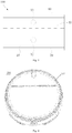
Classifications
-
- A—HUMAN NECESSITIES
- A47—FURNITURE; DOMESTIC ARTICLES OR APPLIANCES; COFFEE MILLS; SPICE MILLS; SUCTION CLEANERS IN GENERAL
- A47L—DOMESTIC WASHING OR CLEANING; SUCTION CLEANERS IN GENERAL
- A47L9/00—Details or accessories of suction cleaners, e.g. mechanical means for controlling the suction or for effecting pulsating action; Storing devices specially adapted to suction cleaners or parts thereof; Carrying-vehicles specially adapted for suction cleaners
- A47L9/10—Filters; Dust separators; Dust removal; Automatic exchange of filters
- A47L9/16—Arrangement or disposition of cyclones or other devices with centrifugal action
- A47L9/1683—Dust collecting chambers; Dust collecting receptacles
-
- A—HUMAN NECESSITIES
- A47—FURNITURE; DOMESTIC ARTICLES OR APPLIANCES; COFFEE MILLS; SPICE MILLS; SUCTION CLEANERS IN GENERAL
- A47L—DOMESTIC WASHING OR CLEANING; SUCTION CLEANERS IN GENERAL
- A47L9/00—Details or accessories of suction cleaners, e.g. mechanical means for controlling the suction or for effecting pulsating action; Storing devices specially adapted to suction cleaners or parts thereof; Carrying-vehicles specially adapted for suction cleaners
- A47L9/10—Filters; Dust separators; Dust removal; Automatic exchange of filters
-
- A—HUMAN NECESSITIES
- A47—FURNITURE; DOMESTIC ARTICLES OR APPLIANCES; COFFEE MILLS; SPICE MILLS; SUCTION CLEANERS IN GENERAL
- A47L—DOMESTIC WASHING OR CLEANING; SUCTION CLEANERS IN GENERAL
- A47L9/00—Details or accessories of suction cleaners, e.g. mechanical means for controlling the suction or for effecting pulsating action; Storing devices specially adapted to suction cleaners or parts thereof; Carrying-vehicles specially adapted for suction cleaners
- A47L9/10—Filters; Dust separators; Dust removal; Automatic exchange of filters
- A47L9/106—Dust removal
-
- A—HUMAN NECESSITIES
- A47—FURNITURE; DOMESTIC ARTICLES OR APPLIANCES; COFFEE MILLS; SPICE MILLS; SUCTION CLEANERS IN GENERAL
- A47L—DOMESTIC WASHING OR CLEANING; SUCTION CLEANERS IN GENERAL
- A47L9/00—Details or accessories of suction cleaners, e.g. mechanical means for controlling the suction or for effecting pulsating action; Storing devices specially adapted to suction cleaners or parts thereof; Carrying-vehicles specially adapted for suction cleaners
- A47L9/10—Filters; Dust separators; Dust removal; Automatic exchange of filters
- A47L9/14—Bags or the like; Rigid filtering receptacles; Attachment of, or closures for, bags or receptacles
-
- A—HUMAN NECESSITIES
- A47—FURNITURE; DOMESTIC ARTICLES OR APPLIANCES; COFFEE MILLS; SPICE MILLS; SUCTION CLEANERS IN GENERAL
- A47L—DOMESTIC WASHING OR CLEANING; SUCTION CLEANERS IN GENERAL
- A47L9/00—Details or accessories of suction cleaners, e.g. mechanical means for controlling the suction or for effecting pulsating action; Storing devices specially adapted to suction cleaners or parts thereof; Carrying-vehicles specially adapted for suction cleaners
- A47L9/10—Filters; Dust separators; Dust removal; Automatic exchange of filters
- A47L9/14—Bags or the like; Rigid filtering receptacles; Attachment of, or closures for, bags or receptacles
- A47L9/1427—Means for mounting or attaching bags or filtering receptacles in suction cleaners; Adapters
- A47L9/1463—Means for mounting or attaching bags or filtering receptacles in suction cleaners; Adapters specially adapted for rigid filtering receptacles
-
- A—HUMAN NECESSITIES
- A47—FURNITURE; DOMESTIC ARTICLES OR APPLIANCES; COFFEE MILLS; SPICE MILLS; SUCTION CLEANERS IN GENERAL
- A47L—DOMESTIC WASHING OR CLEANING; SUCTION CLEANERS IN GENERAL
- A47L9/00—Details or accessories of suction cleaners, e.g. mechanical means for controlling the suction or for effecting pulsating action; Storing devices specially adapted to suction cleaners or parts thereof; Carrying-vehicles specially adapted for suction cleaners
- A47L9/10—Filters; Dust separators; Dust removal; Automatic exchange of filters
- A47L9/14—Bags or the like; Rigid filtering receptacles; Attachment of, or closures for, bags or receptacles
- A47L9/149—Emptying means; Reusable bags
-
- A—HUMAN NECESSITIES
- A47—FURNITURE; DOMESTIC ARTICLES OR APPLIANCES; COFFEE MILLS; SPICE MILLS; SUCTION CLEANERS IN GENERAL
- A47L—DOMESTIC WASHING OR CLEANING; SUCTION CLEANERS IN GENERAL
- A47L9/00—Details or accessories of suction cleaners, e.g. mechanical means for controlling the suction or for effecting pulsating action; Storing devices specially adapted to suction cleaners or parts thereof; Carrying-vehicles specially adapted for suction cleaners
- A47L9/10—Filters; Dust separators; Dust removal; Automatic exchange of filters
- A47L9/16—Arrangement or disposition of cyclones or other devices with centrifugal action
- A47L9/1691—Mounting or coupling means for cyclonic chamber or dust receptacles
-
- A—HUMAN NECESSITIES
- A47—FURNITURE; DOMESTIC ARTICLES OR APPLIANCES; COFFEE MILLS; SPICE MILLS; SUCTION CLEANERS IN GENERAL
- A47L—DOMESTIC WASHING OR CLEANING; SUCTION CLEANERS IN GENERAL
- A47L2201/00—Robotic cleaning machines, i.e. with automatic control of the travelling movement or the cleaning operation
-
- A—HUMAN NECESSITIES
- A47—FURNITURE; DOMESTIC ARTICLES OR APPLIANCES; COFFEE MILLS; SPICE MILLS; SUCTION CLEANERS IN GENERAL
- A47L—DOMESTIC WASHING OR CLEANING; SUCTION CLEANERS IN GENERAL
- A47L2201/00—Robotic cleaning machines, i.e. with automatic control of the travelling movement or the cleaning operation
- A47L2201/02—Docking stations; Docking operations
- A47L2201/024—Emptying dust or waste liquid containers
Definitions
- the present disclosure relates to a technical field of robot vacuum cleaners, and more particularly to a dust collection box and a robot vacuum cleaner.
- a robot vacuum cleaner In daily life, a robot vacuum cleaner satisfies a basic requirement of a user for cleaning the floor, but after a dust collection box in the robot vacuum cleaner is filled with pollutants like rubbish, the user needs to perform complicated operations to remove the garbage in the dust collection box, which is extremely inconvenient.
- Embodiments of the present disclosure provide a dust collection box and a robot vacuum cleaner.
- the dust collection box includes: a box body provided with a dust extraction port in a bottom of the box body; and a lower lid including a first lateral portion and a second lateral portion opposite to each other, the first lateral portion being rotatably connected with the box body to enable the lower lid to open or close the dust extraction port, and when the lower lid closes the dust extraction port, the second lateral portion being snap-fitted with the box body through a first snap structure, and the lower lid being used to carry pollutants.
- the lower lid includes a bottom wall and a lateral wall extending from an edge of the bottom wall, and the bottom wall and the lateral wall enclose a groove; when the lower lid closes the dust extraction port, the bottom of the box body protrudes into the groove, and the lateral wall surrounds the bottom of the box body.
- the box body is provided with a dust collecting chamber in communication with the dust extraction port;
- the lower lid includes a bump fixed on the bottom wall and received in the groove; when the lower lid closes the dust extraction port, the bump extends into the dust collecting chamber and fills a bottom of the dust collecting chamber.
- the box body includes an outer peripheral surface and a bottom surface connected with the outer peripheral surface, and a receiving groove is defined at a joint of the outer peripheral surface and the bottom surface; when the lower lid closes the dust extraction port, the lateral wall is received in the receiving groove, and the outer peripheral surface is in smooth transition with an outer side of the lateral wall.
- the dust collection box includes a button, the button includes a rotating shaft, and the button is rotatably arranged to the box body through the rotating shaft;
- the first snap structure includes a hook formed at an end of the button and a snapping part formed at the second lateral portion; the button is able to swing, with respect to the box body, between a first position and a second position. When in the first position, the hook is snap-fitted with the snapping part so that the lower lid closes the dust extraction port.
- the hook includes a snapping surface facing upwards
- the snapping part includes a snapping bar
- the snapping bar in the first position, the snapping bar abuts against the snapping surface
- the button includes a press board, and the rotating shaft is fixed in a middle position of the press board; the press board includes a first swing end and a second swing end located at two opposite sides of the rotating shaft respectively; the hook is provided at the first swing end, the first swing end swings towards a direction away from the box body, and the second swing end swings towards a direction approaching the box body; and the box body is provided with a void space available for the second swing end to swing.
- a top of the box body is provided with an opening in communication with the dust extraction port, and the dust collection box further includes an upper lid detachably arranged to the top of the box body and covering the opening.
- the upper lid is connected with the box body through a second snap structure.
- the robot vacuum cleaner includes a casing and the dust collection box according to any one of the above embodiments.
- the dust collection box is arranged in the casing.
- dust collection box 100 box body 10, dust extraction port 11, air inlet 12, air outlet 13, dust collecting chamber 14, outer peripheral surface 15, bottom surface 16, receiving groove 17, lower lid 20, first lateral portion 21, second lateral portion 22, bottom wall 23, lateral wall 24, groove 25, bump 26, first snap structure 30, hook 31, snapping surface 311, snapping part 32, snapping bar 321, filter device 40, button 50, rotating shaft 51, press board 52, first swing end 521, second swing end 522, upper lid 60, second snap structure 70, robot vacuum cleaner 200, casing 210.
- first and second are used herein for purposes of description and are not intended to indicate or imply relative importance or significance or to imply the number of indicated technical features.
- the feature provided with “first” and “second” may comprise one or more of this feature.
- a plurality of' means two or more than two, unless specified otherwise.
- the terms “mounted,” “connected,” and “coupled” and variations thereof are used broadly and may be, for example, fixed connections, detachable connections, or integral connections; may also be mechanical or electrical connections; may also be direct connections or indirect connections via intervening structures; may also be inner communications or interaction of two elements, which can be understood by those skilled in the art according to specific situations.
- a structure in which a first feature is "on" or “below” a second feature may include an embodiment in which the first feature is in direct contact with the second feature, and may also include an embodiment in which the first feature and the second feature are not in direct contact with each other, but are contacted via an additional feature formed therebetween.
- a first feature "on,” “above,” or “on top of' a second feature may include an embodiment in which the first feature is right or obliquely “on,” “above,” or “on top of' the second feature, or just means that the first feature is at a height higher than that of the second feature; while a first feature "below,” “under,” or “on bottom of' a second feature may include an embodiment in which the first feature is right or obliquely “below,” “under,” or “on bottom of' the second feature, or just means that the first feature is at a height lower than that of the second feature.
- a dust collection box 100 includes a box body 10 and a lower lid 20.
- the box body 10 is provided with a dust extraction port 11 in a bottom of the box body 10.
- the lower lid 20 includes a first lateral portion 21 and a second lateral portion 22.
- the first lateral portion 21 is rotatably connected with the box body 10 so that the lower lid 20 opens or closes the dust extraction port 11.
- the second lateral portion 22 is snap-fitted with the box body 10 through a first snap structure 30.
- the lower lid 20 is used to carry pollutants.
- the dust collection box 100 can be applied in a robot vacuum cleaner 200.
- the robot vacuum cleaner 200 includes a casing 210, and the dust collection box 100 is arranged in the casing 210.
- the lower lid 20 is connected with the box body 10 through the first snap structure 30, such that the lower lid 20 can easily open the dust extraction port 11, and dust or other rubbish in the box body 10 can be removed from the box body 10, which is convenient to operate.
- the dust collection box 100 is first taken out from the robot vacuum cleaner 200, the snap-fit relationship between the lower lid 20 and the box body 10 is released, such that the lower lid 20 can rotate to open the dust extraction port 11 and hence the dust carried by the lower lid 20 flows out of the box body 10 along with the rotation of the lower lid 20.
- the lower lid 20 can rotate to open the dust extraction port 11 and hence the dust carried by the lower lid 20 flows out of the box body 10 along with the rotation of the lower lid 20.
- the box body 10 is provided with an air inlet 12 and an air outlet 13, and the air inlet 12 and the air outlet 13 may be located at the same lateral surface of the box body 10.
- the air inlet 12 is located in a lower portion of the box body 10, while the air outlet 13 is located in an upper portion of the box body 10.
- the box body 10 is internally provided with a filter device 40, and the filter device 40 is located between the air inlet 12 and the air outlet 13.
- the robot vacuum cleaner 200 operates, an air flow is formed between the air inlet 12 and the air outlet 13, and the dust and other pollutants enter the box body 10 from the air inlet 12 along with the air flow. Due to a filtration effect of the filter device 40, the pollutants are blocked from flowing to the air outlet 13 and instead remain in the box body 10, whereby a dedusting effect is realized.
- the first lateral portion 21 can be rotatably connected to the box body 10 in the following manner.
- the first lateral portion 21 is provided with a rotating shaft
- the box body 10 is provided with a rotating hole
- the rotating shaft is received in the rotating hole to realize the rotatable connection between the first lateral portion 21 and the box body 10.
- a bottom direction is a downward direction illustrated in Fig. 2
- a top direction is an upward direction illustrated in Fig. 2 .
- the lower lid 20 includes a bottom wall 23 and a lateral wall 24 extending from an edge of the bottom wall 23, and the bottom wall 23 and the lateral wall 24 enclose a groove 25.
- the lower lid 20 closes the dust extraction port 11, the bottom of the box body 10 protrudes into the groove 25, and the lateral wall 24 surrounds the bottom of the box body 10.
- the lateral wall 24 surrounds the bottom of the box body 10, so that the dust extraction port 11 is covered more tightly, the pollutants are prevented from flowing out of the dust extraction port during the dust collection process, which may otherwise pollute internal components of the robot vacuum cleaner 200, and the service life of the robot vacuum cleaner 200 is prolonged.
- the box body 10 is provided with a dust collecting chamber 14 in communication with the dust extraction port 11.
- the lower lid 20 includes a bump 26 fixed on the bottom wall 23 and received in the groove 25. When the lower lid 20 closes the dust extraction port 11, the bump 26 extends into the dust collecting chamber 14 and fills the bottom of the dust collecting chamber 14. Thus, the bump 26 can further improve tightness of the dust extraction port 11 to prevent the pollutants from flowing out of the box body 10.
- the box body 10 includes an outer peripheral surface 15 and a bottom surface 16 connected with the outer peripheral surface 15, and a receiving groove 17 is provided at a joint of the outer peripheral surface 15 and the bottom surface 16.
- the lower lid 20 closes the dust extraction port 11
- the lateral wall 24 is received in the receiving groove 17, and the outer peripheral surface 15 is in smooth transitioned with an outer side of the lateral wall 24.
- the lower lid 20 is connected to the box body 10 in a smooth transition, such that the periphery of the dust collection box 100 is smoother, which is advantageous to mounting the dust collection box 100 into the robot vacuum cleaner 200 or removing the dust collection box 100 from the robot vacuum cleaner 200.
- the dust collection box 100 includes a button 50.
- the button 50 includes a rotating shaft 51 and is rotatably arranged to the box body 10 through the rotating shaft 51.
- the first snap structure 30 includes a hook 31 formed at an end of the button 50 and a snapping part 32 formed at the second lateral portion 22.
- the button 50 can swing between a first position and a second position with respect to the box body 10. In the first position, the hook 31 is snap-fitted with the snapping part 32 so that the lower lid 20 closes the dust extraction port 11. Additionally, in the second position, the hook 31 is disengaged from the snapping part 32 to enable the lower lid 20 to rotate with respect the box body 10.
- the hook 31 is disengaged from the snapping part 32 so that the lower lid 20 rotates to open the dust extraction port 11 to discharge the pollutants, which is a simple dust exhaust manner.
- the hook 31 includes a snapping surface 311 facing upwards
- the snapping part 32 includes a snapping bar 321, and in the first position, the snapping bar 321 abuts against the snapping surface 311.
- the button 50 includes a press board 52, and the rotating shaft 51 is fixed in a middle position of the press board 52.
- the press board 52 includes a first swing end 521 and a second swing end 522 located at two opposite sides of the rotating shaft 51 respectively.
- the hook 31 is provided at voithe first swing end 521, the first swing end 521 swings towards a direction away from the box body 10, and the second swing end 522 swings towards a direction approaching the box body 10.
- the box body 10 is provided with a void space 18 for swinging the second swing end 522.
- the void space 18 can prevent the button 50 from interfering with the box body 10 during the rotation.
- the top of the box body 10 is provided with an opening in communication with the dust extraction port 11, and the dust collection box 100 further includes an upper lid 60 detachably arranged to the top of the box body 10 and covering the opening.
- the filter device 40 is easily taken out from the box body 10 and mounted into the box body 10.
- the upper lid 60 is connected with the box body 10 through a second snap structure 70. Thus, the upper lid 60 can be easily removed.
Landscapes
- Engineering & Computer Science (AREA)
- Mechanical Engineering (AREA)
- Filters For Electric Vacuum Cleaners (AREA)
- Electric Suction Cleaners (AREA)
- Electric Vacuum Cleaner (AREA)
Abstract
Description
- This application claims priority to and the benefit of Chinese Patent Application No.
201820321909.0 - The present disclosure relates to a technical field of robot vacuum cleaners, and more particularly to a dust collection box and a robot vacuum cleaner.
- In daily life, a robot vacuum cleaner satisfies a basic requirement of a user for cleaning the floor, but after a dust collection box in the robot vacuum cleaner is filled with pollutants like rubbish, the user needs to perform complicated operations to remove the garbage in the dust collection box, which is extremely inconvenient.
- Embodiments of the present disclosure provide a dust collection box and a robot vacuum cleaner.
- The dust collection box according to embodiments of the present disclosure includes: a box body provided with a dust extraction port in a bottom of the box body; and a lower lid including a first lateral portion and a second lateral portion opposite to each other, the first lateral portion being rotatably connected with the box body to enable the lower lid to open or close the dust extraction port, and when the lower lid closes the dust extraction port, the second lateral portion being snap-fitted with the box body through a first snap structure, and the lower lid being used to carry pollutants.
- In some embodiments, the lower lid includes a bottom wall and a lateral wall extending from an edge of the bottom wall, and the bottom wall and the lateral wall enclose a groove; when the lower lid closes the dust extraction port, the bottom of the box body protrudes into the groove, and the lateral wall surrounds the bottom of the box body.
- In some embodiments, the box body is provided with a dust collecting chamber in communication with the dust extraction port; the lower lid includes a bump fixed on the bottom wall and received in the groove; when the lower lid closes the dust extraction port, the bump extends into the dust collecting chamber and fills a bottom of the dust collecting chamber.
- In some embodiments, the box body includes an outer peripheral surface and a bottom surface connected with the outer peripheral surface, and a receiving groove is defined at a joint of the outer peripheral surface and the bottom surface; when the lower lid closes the dust extraction port, the lateral wall is received in the receiving groove, and the outer peripheral surface is in smooth transition with an outer side of the lateral wall.
- In some embodiments, the dust collection box includes a button, the button includes a rotating shaft, and the button is rotatably arranged to the box body through the rotating shaft; the first snap structure includes a hook formed at an end of the button and a snapping part formed at the second lateral portion; the button is able to swing, with respect to the box body, between a first position and a second position. When in the first position, the hook is snap-fitted with the snapping part so that the lower lid closes the dust extraction port.
- In some embodiments, the hook includes a snapping surface facing upwards, the snapping part includes a snapping bar, and in the first position, the snapping bar abuts against the snapping surface.
- In some embodiments, the button includes a press board, and the rotating shaft is fixed in a middle position of the press board; the press board includes a first swing end and a second swing end located at two opposite sides of the rotating shaft respectively; the hook is provided at the first swing end, the first swing end swings towards a direction away from the box body, and the second swing end swings towards a direction approaching the box body; and the box body is provided with a void space available for the second swing end to swing.
- In some embodiments, a top of the box body is provided with an opening in communication with the dust extraction port, and the dust collection box further includes an upper lid detachably arranged to the top of the box body and covering the opening.
- In some embodiments, the upper lid is connected with the box body through a second snap structure.
- The robot vacuum cleaner according to embodiments of the present disclosure includes a casing and the dust collection box according to any one of the above embodiments. The dust collection box is arranged in the casing.
- Additional aspects and advantages of the present disclosure will be given in part in the following descriptions, become apparent in part from the following descriptions, or be learned from the practice of the embodiments of the present disclosure.
- These and/or other aspects and advantages of the present disclosure will become apparent and more readily appreciated from the following descriptions of embodiments made with reference to the drawings, in which:
-
Fig. 1 is a perspective view of a dust collection box according to an embodiment of the present disclosure. -
Fig. 2 is a perspective exploded view of a dust collection box according to an embodiment of the present disclosure. -
Fig. 3 is a side view of a dust collection box according to an embodiment of the present disclosure. -
Fig. 4 is a plan view of a robot vacuum cleaner according to an embodiment of the present disclosure. - Main reference numerals:
dust collection box 100,box body 10,dust extraction port 11,air inlet 12,air outlet 13,dust collecting chamber 14, outerperipheral surface 15,bottom surface 16, receivinggroove 17,lower lid 20, firstlateral portion 21, secondlateral portion 22,bottom wall 23,lateral wall 24, groove 25,bump 26,first snap structure 30,hook 31,snapping surface 311,snapping part 32,snapping bar 321,filter device 40,button 50, rotatingshaft 51,press board 52,first swing end 521,second swing end 522,upper lid 60,second snap structure 70,robot vacuum cleaner 200,casing 210. - Reference will be made in detail to embodiments of the present disclosure. Examples of the embodiments are shown in the drawings. The same or similar elements and the elements having same or similar functions are denoted by like reference numerals throughout the descriptions. The embodiments described herein with reference to drawings are explanatory, illustrative, and used to generally understand the present disclosure. The embodiments shall not be construed to limit the present disclosure.
- In the specification, it is to be understood that terms such as "central," "longitudinal," "transverse," "length," "width," "thickness," "upper," "lower," "front," "rear," "left," "right," "vertical," "horizontal," "top," "bottom," "inner," "outer," "clockwise," and "counterclockwise" should be construed to refer to the orientation as then described or as shown in the drawings under discussion. These relative terms are for convenience of description and do not require that the present disclosure have a particular orientation or be constructed or operated in a particular orientation. Thus, these terms cannot be constructed to limit the present disclosure. In addition, terms such as "first" and "second" are used herein for purposes of description and are not intended to indicate or imply relative importance or significance or to imply the number of indicated technical features. Thus, the feature provided with "first" and "second" may comprise one or more of this feature. In the description of the present disclosure, "a plurality of' means two or more than two, unless specified otherwise.
- In the description of the present disclosure, it should be understood that, unless specified or limited otherwise, the terms "mounted," "connected," and "coupled" and variations thereof are used broadly and may be, for example, fixed connections, detachable connections, or integral connections; may also be mechanical or electrical connections; may also be direct connections or indirect connections via intervening structures; may also be inner communications or interaction of two elements, which can be understood by those skilled in the art according to specific situations.
- In the present disclosure, unless specified or limited otherwise, a structure in which a first feature is "on" or "below" a second feature may include an embodiment in which the first feature is in direct contact with the second feature, and may also include an embodiment in which the first feature and the second feature are not in direct contact with each other, but are contacted via an additional feature formed therebetween. Furthermore, a first feature "on," "above," or "on top of' a second feature may include an embodiment in which the first feature is right or obliquely "on," "above," or "on top of' the second feature, or just means that the first feature is at a height higher than that of the second feature; while a first feature "below," "under," or "on bottom of' a second feature may include an embodiment in which the first feature is right or obliquely "below," "under," or "on bottom of' the second feature, or just means that the first feature is at a height lower than that of the second feature.
- Various embodiments and examples are provided in the following description to implement different structures of the present disclosure. In order to simplify the present disclosure, certain elements and settings are described above. However, these elements and settings are only by way of example and are not intended to limit the present disclosure. In addition, reference numerals and/or reference letters may be repeated in different examples in the present disclosure. This repetition is for the purpose of simplification and clarity, and does not refer to relations between different embodiments and/or settings. Furthermore, examples of different processes and materials are provided in the present disclosure. However, it would be appreciated by those skilled in the art that other processes and/or materials may be also applied.
- Referring to
Figs. 1 and2 , adust collection box 100 according to embodiments of the present disclosure includes abox body 10 and alower lid 20. Thebox body 10 is provided with adust extraction port 11 in a bottom of thebox body 10. Thelower lid 20 includes a firstlateral portion 21 and a secondlateral portion 22. The firstlateral portion 21 is rotatably connected with thebox body 10 so that thelower lid 20 opens or closes thedust extraction port 11. When thelower lid 20 closes thedust extraction port 11, the secondlateral portion 22 is snap-fitted with thebox body 10 through afirst snap structure 30. Thelower lid 20 is used to carry pollutants. - Referring to
Fig. 4 , thedust collection box 100 can be applied in arobot vacuum cleaner 200. Specifically, therobot vacuum cleaner 200 includes acasing 210, and thedust collection box 100 is arranged in thecasing 210. - In the
dust collection box 100 and therobot vacuum cleaner 200 discussed above, thelower lid 20 is connected with thebox body 10 through thefirst snap structure 30, such that thelower lid 20 can easily open thedust extraction port 11, and dust or other rubbish in thebox body 10 can be removed from thebox body 10, which is convenient to operate. - Specifically, when the dust in the
robot vacuum cleaner 200 is cleared away, thedust collection box 100 is first taken out from therobot vacuum cleaner 200, the snap-fit relationship between thelower lid 20 and thebox body 10 is released, such that thelower lid 20 can rotate to open thedust extraction port 11 and hence the dust carried by thelower lid 20 flows out of thebox body 10 along with the rotation of thelower lid 20. In such a way, it is unnecessary to take out a filter device from thebox body 10 during the removal of pollutants, which facilitates the cleaning process. - Referring to
Fig. 3 , thebox body 10 is provided with anair inlet 12 and anair outlet 13, and theair inlet 12 and theair outlet 13 may be located at the same lateral surface of thebox body 10. Theair inlet 12 is located in a lower portion of thebox body 10, while theair outlet 13 is located in an upper portion of thebox body 10. Thebox body 10 is internally provided with afilter device 40, and thefilter device 40 is located between theair inlet 12 and theair outlet 13. When therobot vacuum cleaner 200 operates, an air flow is formed between theair inlet 12 and theair outlet 13, and the dust and other pollutants enter thebox body 10 from theair inlet 12 along with the air flow. Due to a filtration effect of thefilter device 40, the pollutants are blocked from flowing to theair outlet 13 and instead remain in thebox body 10, whereby a dedusting effect is realized. - The first
lateral portion 21 can be rotatably connected to thebox body 10 in the following manner. For example, the firstlateral portion 21 is provided with a rotating shaft, thebox body 10 is provided with a rotating hole, and the rotating shaft is received in the rotating hole to realize the rotatable connection between the firstlateral portion 21 and thebox body 10. - It should be noted that a bottom direction is a downward direction illustrated in
Fig. 2 , and a top direction is an upward direction illustrated inFig. 2 . - Referring to
Figs. 1 and2 again, in some embodiments, thelower lid 20 includes abottom wall 23 and alateral wall 24 extending from an edge of thebottom wall 23, and thebottom wall 23 and thelateral wall 24 enclose a groove 25. When thelower lid 20 closes thedust extraction port 11, the bottom of thebox body 10 protrudes into the groove 25, and thelateral wall 24 surrounds the bottom of thebox body 10. - Thus, the
lateral wall 24 surrounds the bottom of thebox body 10, so that thedust extraction port 11 is covered more tightly, the pollutants are prevented from flowing out of the dust extraction port during the dust collection process, which may otherwise pollute internal components of therobot vacuum cleaner 200, and the service life of therobot vacuum cleaner 200 is prolonged. - In some embodiments, the
box body 10 is provided with adust collecting chamber 14 in communication with thedust extraction port 11. Thelower lid 20 includes abump 26 fixed on thebottom wall 23 and received in the groove 25. When thelower lid 20 closes thedust extraction port 11, thebump 26 extends into thedust collecting chamber 14 and fills the bottom of thedust collecting chamber 14. Thus, thebump 26 can further improve tightness of thedust extraction port 11 to prevent the pollutants from flowing out of thebox body 10. - In some embodiments, the
box body 10 includes an outerperipheral surface 15 and abottom surface 16 connected with the outerperipheral surface 15, and a receivinggroove 17 is provided at a joint of the outerperipheral surface 15 and thebottom surface 16. When thelower lid 20 closes thedust extraction port 11, thelateral wall 24 is received in the receivinggroove 17, and the outerperipheral surface 15 is in smooth transitioned with an outer side of thelateral wall 24. As a result, thelower lid 20 is connected to thebox body 10 in a smooth transition, such that the periphery of thedust collection box 100 is smoother, which is advantageous to mounting thedust collection box 100 into therobot vacuum cleaner 200 or removing thedust collection box 100 from therobot vacuum cleaner 200. - In some embodiments, the
dust collection box 100 includes abutton 50. Thebutton 50 includes arotating shaft 51 and is rotatably arranged to thebox body 10 through the rotatingshaft 51. Thefirst snap structure 30 includes ahook 31 formed at an end of thebutton 50 and a snappingpart 32 formed at the secondlateral portion 22. Thebutton 50 can swing between a first position and a second position with respect to thebox body 10. In the first position, thehook 31 is snap-fitted with the snappingpart 32 so that thelower lid 20 closes thedust extraction port 11. Additionally, in the second position, thehook 31 is disengaged from the snappingpart 32 to enable thelower lid 20 to rotate with respect thebox body 10. - Thus, after the
button 50 is pressed down, thehook 31 is disengaged from the snappingpart 32 so that thelower lid 20 rotates to open thedust extraction port 11 to discharge the pollutants, which is a simple dust exhaust manner. - Specifically, the
hook 31 includes a snappingsurface 311 facing upwards, the snappingpart 32 includes a snappingbar 321, and in the first position, the snappingbar 321 abuts against the snappingsurface 311. - In some embodiments, the
button 50 includes apress board 52, and therotating shaft 51 is fixed in a middle position of thepress board 52. Thepress board 52 includes afirst swing end 521 and asecond swing end 522 located at two opposite sides of therotating shaft 51 respectively. Thehook 31 is provided at voithefirst swing end 521, thefirst swing end 521 swings towards a direction away from thebox body 10, and thesecond swing end 522 swings towards a direction approaching thebox body 10. Thebox body 10 is provided with avoid space 18 for swinging thesecond swing end 522. - As a result, the
void space 18 can prevent thebutton 50 from interfering with thebox body 10 during the rotation. - In some embodiments, the top of the
box body 10 is provided with an opening in communication with thedust extraction port 11, and thedust collection box 100 further includes anupper lid 60 detachably arranged to the top of thebox body 10 and covering the opening. - Thus, after the
upper lid 60 is removed, thefilter device 40 is easily taken out from thebox body 10 and mounted into thebox body 10. - In some embodiments, the
upper lid 60 is connected with thebox body 10 through asecond snap structure 70. Thus, theupper lid 60 can be easily removed. - Reference throughout this specification to "an embodiment," "some embodiments," "an exemplary embodiment," "an example," "specific examples" or "some examples" means that a particular feature, structure, material, or characteristic described in connection with the embodiment or example is included in at least one embodiment or example of the present disclosure. Thus, the appearances of the above phrases throughout this specification are not necessarily referring to the same embodiment or example of the present disclosure. Furthermore, the particular features, structures, materials, or characteristics may be combined in any suitable manner in one or more embodiments or examples.
- Although embodiments of the present disclosure have been shown and illustrated, it shall be understood by those skilled in the art that various changes, modifications, alternatives and variations without departing from the principle of the present disclosure are acceptable. The scope of the present disclosure is provided by the claims or the like.
Claims (10)
- A dust collection box, comprising:a box body provided with a dust extraction port in a bottom of the box body; anda lower lid comprising a first lateral portion and a second lateral portion opposite to each other, the first lateral portion being rotatably connected with the box body to enable the lower lid to open or close the dust extraction port, and when the lower lid closes the dust extraction port, the second lateral portion being snap-fitted with the box body through a first snap structure, and the lower lid being used to carry pollutants.
- The dust collection box according to claim 1, wherein the lower lid comprises a bottom wall and a lateral wall extending from an edge of the bottom wall, and the bottom wall and the lateral wall enclose a groove; when the lower lid closes the dust extraction port, the bottom of the box body protrudes into the groove, and the lateral wall surrounds the bottom of the box body.
- The dust collection box according to claim 2, wherein the box body is provided with a dust collecting chamber in communication with the dust extraction port; the lower lid comprises a bump fixed on the bottom wall and received in the groove; when the lower lid closes the dust extraction port, the bump extends into the dust collecting chamber and fills a bottom of the dust collecting chamber.
- The dust collection box according to claim 2, wherein the box body comprises an outer peripheral surface and a bottom surface connected with the outer peripheral surface, and a receiving groove is formed at a joint portion of the outer peripheral surface and the bottom surface; when the lower lid closes the dust extraction port, the lateral wall is received in the receiving groove, and the outer peripheral surface is in smooth transition with an outer side of the lateral wall.
- The dust collection box according to claim 1, wherein the dust collection box comprises a button, the button comprises a rotating shaft, and the button is rotatably arranged to the box body through the rotating shaft; the first snap structure comprises a hook formed at an end of the button and a snapping part formed at the second lateral portion; the button is able to swing with respect to the box body (10) between a first position and a second position, wherein in the first position the hook is snap-fitted with the snapping part so that the lower lid closes the dust extraction port,.
- The dust collection box according to claim 5, wherein the hook comprises a snapping surface facing upwards, the snapping part comprises a snapping bar, and in the first position, the snapping bar abuts against the snapping surface.
- The dust collection box according to claim 5, wherein the button comprises a press board, and the rotating shaft is fixed in a middle position of the press board; the press board comprises a first swing end and a second swing end located at two opposite sides of the rotating shaft respectively; the hook is provided at the first swing end, the first swing end swings towards a direction away from the box body, and the second swing end swings towards a direction approaching the box body; and the box body is provided with a void space for swinging the second swing end .
- The dust collection box according to claim 1, wherein a top of the box body is provided with an opening in communication with the dust extraction port, and the dust collection box further comprises an upper lid detachably arranged to the top of the box body and covering the opening.
- The dust collection box according to claim 8, wherein the upper lid is connected with the box body through a second snap structure.
- A robot vacuum cleaner, comprising:a casing; anda dust collection box according to any one of claims 1 to 9, the dust collection box being arranged in the casing.
Applications Claiming Priority (2)
| Application Number | Priority Date | Filing Date | Title |
|---|---|---|---|
| CN201820321909.0U CN208435500U (en) | 2018-03-08 | 2018-03-08 | Dust box and sweeping robot |
| PCT/CN2018/098032 WO2019169827A1 (en) | 2018-03-08 | 2018-08-01 | Dust collection box and sweeping robot |
Publications (3)
| Publication Number | Publication Date |
|---|---|
| EP3741278A1 true EP3741278A1 (en) | 2020-11-25 |
| EP3741278A4 EP3741278A4 (en) | 2021-03-10 |
| EP3741278B1 EP3741278B1 (en) | 2023-12-13 |
Family
ID=65095313
Family Applications (1)
| Application Number | Title | Priority Date | Filing Date |
|---|---|---|---|
| EP18909213.3A Active EP3741278B1 (en) | 2018-03-08 | 2018-08-01 | Dust collection box and sweeping robot |
Country Status (7)
| Country | Link |
|---|---|
| US (1) | US10335001B1 (en) |
| EP (1) | EP3741278B1 (en) |
| JP (1) | JP2021516100A (en) |
| KR (1) | KR20200119286A (en) |
| CN (1) | CN208435500U (en) |
| ES (1) | ES2971651T3 (en) |
| WO (1) | WO2019169827A1 (en) |
Cited By (1)
| Publication number | Priority date | Publication date | Assignee | Title |
|---|---|---|---|---|
| CN113951759A (en) * | 2021-09-16 | 2022-01-21 | 添可智能科技有限公司 | Handheld dust collector, dust collector and dust collecting device |
Families Citing this family (14)
| Publication number | Priority date | Publication date | Assignee | Title |
|---|---|---|---|---|
| US10952578B2 (en) | 2018-07-20 | 2021-03-23 | Sharkninja Operating Llc | Robotic cleaner debris removal docking station |
| CN112213968B (en) * | 2019-07-12 | 2022-05-20 | 江苏美的清洁电器股份有限公司 | Dust collection station, control method, control device, equipment and storage medium thereof |
| CN110876589B (en) * | 2019-12-24 | 2024-10-11 | 美智纵横科技有限责任公司 | Dust box assembly of sweeping robot and sweeping robot |
| CN111150336A (en) * | 2020-02-25 | 2020-05-15 | 珠海市一微半导体有限公司 | A kind of dust box for sweeping robot and sweeping robot |
| CN113243826B (en) * | 2020-04-02 | 2022-10-11 | 尚科宁家(中国)科技有限公司 | Electric broom |
| CN111633497A (en) * | 2020-05-08 | 2020-09-08 | 苏州高之仙自动化科技有限公司 | Workstation and method of operation |
| CN111543901A (en) * | 2020-05-29 | 2020-08-18 | 深圳市银星智能科技股份有限公司 | Cleaning base stations and cleaning robot systems |
| CN114098523A (en) * | 2020-08-26 | 2022-03-01 | 苏州三六零机器人科技有限公司 | Dust collecting box and sweeping robot |
| CN112022008B (en) * | 2020-09-08 | 2022-06-03 | 海南经贸职业技术学院 | Intelligent house of deashing fast robot of sweeping floor |
| CN116379540B (en) * | 2021-12-23 | 2026-02-10 | 宁波奥克斯电气有限公司 | Dust collection box and air conditioner |
| CN114273365B (en) * | 2021-12-24 | 2023-08-22 | 湖北仕上电子科技有限公司 | Cleaning device for liquid crystal glass semi-finished product |
| TWD222441S (en) * | 2022-01-05 | 2022-12-01 | 大陸商北京石頭世紀科技股份有限公司 | Dust box |
| CN114886329B (en) * | 2022-05-13 | 2025-10-31 | 杭州萤石软件有限公司 | Dust collection box of cleaning robot and cleaning robot |
| USD1093789S1 (en) * | 2023-06-25 | 2025-09-16 | Yunjing Intelligence Innovation (Shenzhen) Co., Ltd. | Cleaning robot |
Family Cites Families (19)
| Publication number | Priority date | Publication date | Assignee | Title |
|---|---|---|---|---|
| JP2004033241A (en) * | 2002-06-28 | 2004-02-05 | Sanyo Electric Co Ltd | Cyclone type dust collector and vacuum cleaner using the same |
| KR20060018017A (en) * | 2004-08-23 | 2006-02-28 | 엘지전자 주식회사 | Dust collection unit of vacuum cleaner |
| JP5012220B2 (en) * | 2007-05-31 | 2012-08-29 | パナソニック株式会社 | Dust collection container and electric vacuum cleaner provided with the same |
| CN101637372A (en) * | 2008-07-31 | 2010-02-03 | 乐金电子(天津)电器有限公司 | Dust collector of vacuum cleaner |
| JP2010057653A (en) * | 2008-09-03 | 2010-03-18 | Panasonic Corp | Vacuum cleaner |
| JP5125921B2 (en) * | 2008-09-11 | 2013-01-23 | パナソニック株式会社 | Electric vacuum cleaner |
| CN201404164Y (en) * | 2009-04-28 | 2010-02-17 | 江苏美的春花电器股份有限公司 | A dust collecting bucket with automatic dust removal |
| CN201431419Y (en) * | 2009-06-04 | 2010-03-31 | 乐长琴 | Dust collector cup |
| CN102138764A (en) * | 2010-02-01 | 2011-08-03 | 乐金电子(天津)电器有限公司 | Dust collection barrel capable of easily opening bottom cover |
| JP2012034759A (en) * | 2010-08-05 | 2012-02-23 | Panasonic Corp | Vacuum cleaner |
| CN102578967A (en) * | 2011-01-10 | 2012-07-18 | 乐金电子(天津)电器有限公司 | Controllable opening structure for bottom cover of dust collection barrel |
| CN202173359U (en) * | 2011-08-05 | 2012-03-28 | 宁波锦隆电器有限公司 | Dust cup of dust collector |
| CN202751335U (en) * | 2012-08-27 | 2013-02-27 | 莱克电气股份有限公司 | Dust collector dust cup with novel bottom cover locking structure |
| JP6522905B2 (en) * | 2014-08-20 | 2019-05-29 | 東芝ライフスタイル株式会社 | Electric vacuum cleaner |
| JP6488137B2 (en) * | 2015-01-28 | 2019-03-20 | 日立アプライアンス株式会社 | Electric vacuum cleaner |
| CN204841212U (en) * | 2015-02-06 | 2015-12-09 | 杭州信多达电器有限公司 | A dust collecting box for an intelligent sweeping robot |
| JP5957135B2 (en) * | 2015-11-20 | 2016-07-27 | シャープ株式会社 | Dust collector and self-propelled vacuum cleaner provided with the same |
| KR101845044B1 (en) * | 2016-04-14 | 2018-04-04 | 엘지전자 주식회사 | Dust collector and vacuum cleaner having the same |
| KR101878675B1 (en) * | 2016-05-20 | 2018-07-18 | 엘지전자 주식회사 | Robot cleaner |
-
2018
- 2018-03-08 CN CN201820321909.0U patent/CN208435500U/en active Active
- 2018-08-01 WO PCT/CN2018/098032 patent/WO2019169827A1/en not_active Ceased
- 2018-08-01 EP EP18909213.3A patent/EP3741278B1/en active Active
- 2018-08-01 KR KR1020207025922A patent/KR20200119286A/en not_active Ceased
- 2018-08-01 JP JP2020546147A patent/JP2021516100A/en active Pending
- 2018-08-01 ES ES18909213T patent/ES2971651T3/en active Active
- 2018-09-13 US US16/131,001 patent/US10335001B1/en active Active
Cited By (1)
| Publication number | Priority date | Publication date | Assignee | Title |
|---|---|---|---|---|
| CN113951759A (en) * | 2021-09-16 | 2022-01-21 | 添可智能科技有限公司 | Handheld dust collector, dust collector and dust collecting device |
Also Published As
| Publication number | Publication date |
|---|---|
| KR20200119286A (en) | 2020-10-19 |
| US10335001B1 (en) | 2019-07-02 |
| EP3741278A4 (en) | 2021-03-10 |
| ES2971651T3 (en) | 2024-06-06 |
| JP2021516100A (en) | 2021-07-01 |
| WO2019169827A1 (en) | 2019-09-12 |
| CN208435500U (en) | 2019-01-29 |
| EP3741278B1 (en) | 2023-12-13 |
Similar Documents
| Publication | Publication Date | Title |
|---|---|---|
| EP3741278A1 (en) | Dust collection box and sweeping robot | |
| EP3741280B1 (en) | Dust box and cleaning robot | |
| EP3741279B1 (en) | Dust collecting bin and sweeping robot | |
| KR100880492B1 (en) | Dust collection unit for vacuum cleaner | |
| CN210871311U (en) | Dust collecting box and sweeping robot thereof | |
| CN113017470B (en) | Handheld dust collector | |
| JPH10304993A (en) | Electric vacuum cleaner for both wet and dry usages | |
| CN211633145U (en) | A dust box and sweeping robot | |
| CN209826560U (en) | Dust cup device and related dust collector thereof | |
| JPH04288111A (en) | vacuum cleaner | |
| CN205514394U (en) | Dirt bucket overhead water filtration dust catcher | |
| JP4966683B2 (en) | Dust collection container for vacuum cleaner | |
| CN214856354U (en) | Hand-held type dust catcher | |
| CN207755228U (en) | Sweeping robot Multifunctional box | |
| CN217118305U (en) | Surface cleaning device | |
| CN218338338U (en) | Dirt cup subassembly and vertical dust catcher | |
| CN217118304U (en) | Surface cleaning device | |
| CN217013895U (en) | Water tank | |
| CN216907767U (en) | Handheld dust collector | |
| CN114468831A (en) | Handheld dust collector | |
| CN218247095U (en) | Dust collection box and cleaning device | |
| CN216060407U (en) | Filter equipment of scrubber | |
| CN215777764U (en) | A dust bucket assembly for a handheld cordless dust collector | |
| CN210095636U (en) | Dust collection box and cleaning robot with leak-proof design | |
| CN217137888U (en) | Dust box pop-up structure |
Legal Events
| Date | Code | Title | Description |
|---|---|---|---|
| STAA | Information on the status of an ep patent application or granted ep patent |
Free format text: STATUS: THE INTERNATIONAL PUBLICATION HAS BEEN MADE |
|
| PUAI | Public reference made under article 153(3) epc to a published international application that has entered the european phase |
Free format text: ORIGINAL CODE: 0009012 |
|
| STAA | Information on the status of an ep patent application or granted ep patent |
Free format text: STATUS: REQUEST FOR EXAMINATION WAS MADE |
|
| 17P | Request for examination filed |
Effective date: 20200821 |
|
| AK | Designated contracting states |
Kind code of ref document: A1 Designated state(s): AL AT BE BG CH CY CZ DE DK EE ES FI FR GB GR HR HU IE IS IT LI LT LU LV MC MK MT NL NO PL PT RO RS SE SI SK SM TR |
|
| AX | Request for extension of the european patent |
Extension state: BA ME |
|
| A4 | Supplementary search report drawn up and despatched |
Effective date: 20210210 |
|
| RIC1 | Information provided on ipc code assigned before grant |
Ipc: A47L 11/40 20060101ALI20210204BHEP Ipc: A47L 9/16 20060101ALI20210204BHEP Ipc: A47L 11/24 20060101ALI20210204BHEP Ipc: A47L 9/10 20060101AFI20210204BHEP |
|
| DAV | Request for validation of the european patent (deleted) | ||
| DAX | Request for extension of the european patent (deleted) | ||
| RAP1 | Party data changed (applicant data changed or rights of an application transferred) |
Owner name: MIDEA ROBOZONE TECHNOLOGY CO., LTD. |
|
| GRAP | Despatch of communication of intention to grant a patent |
Free format text: ORIGINAL CODE: EPIDOSNIGR1 |
|
| STAA | Information on the status of an ep patent application or granted ep patent |
Free format text: STATUS: GRANT OF PATENT IS INTENDED |
|
| INTG | Intention to grant announced |
Effective date: 20230309 |
|
| GRAJ | Information related to disapproval of communication of intention to grant by the applicant or resumption of examination proceedings by the epo deleted |
Free format text: ORIGINAL CODE: EPIDOSDIGR1 |
|
| STAA | Information on the status of an ep patent application or granted ep patent |
Free format text: STATUS: REQUEST FOR EXAMINATION WAS MADE |
|
| GRAS | Grant fee paid |
Free format text: ORIGINAL CODE: EPIDOSNIGR3 |
|
| STAA | Information on the status of an ep patent application or granted ep patent |
Free format text: STATUS: GRANT OF PATENT IS INTENDED |
|
| GRAP | Despatch of communication of intention to grant a patent |
Free format text: ORIGINAL CODE: EPIDOSNIGR1 |
|
| INTC | Intention to grant announced (deleted) | ||
| INTG | Intention to grant announced |
Effective date: 20230804 |
|
| GRAA | (expected) grant |
Free format text: ORIGINAL CODE: 0009210 |
|
| STAA | Information on the status of an ep patent application or granted ep patent |
Free format text: STATUS: THE PATENT HAS BEEN GRANTED |
|
| AK | Designated contracting states |
Kind code of ref document: B1 Designated state(s): AL AT BE BG CH CY CZ DE DK EE ES FI FR GB GR HR HU IE IS IT LI LT LU LV MC MK MT NL NO PL PT RO RS SE SI SK SM TR |
|
| REG | Reference to a national code |
Ref country code: GB Ref legal event code: FG4D |
|
| REG | Reference to a national code |
Ref country code: CH Ref legal event code: EP |
|
| REG | Reference to a national code |
Ref country code: DE Ref legal event code: R096 Ref document number: 602018062770 Country of ref document: DE |
|
| REG | Reference to a national code |
Ref country code: IE Ref legal event code: FG4D |
|
| PG25 | Lapsed in a contracting state [announced via postgrant information from national office to epo] |
Ref country code: GR Free format text: LAPSE BECAUSE OF FAILURE TO SUBMIT A TRANSLATION OF THE DESCRIPTION OR TO PAY THE FEE WITHIN THE PRESCRIBED TIME-LIMIT Effective date: 20240314 |
|
| REG | Reference to a national code |
Ref country code: LT Ref legal event code: MG9D |
|
| PG25 | Lapsed in a contracting state [announced via postgrant information from national office to epo] |
Ref country code: LT Free format text: LAPSE BECAUSE OF FAILURE TO SUBMIT A TRANSLATION OF THE DESCRIPTION OR TO PAY THE FEE WITHIN THE PRESCRIBED TIME-LIMIT Effective date: 20231213 |
|
| REG | Reference to a national code |
Ref country code: NL Ref legal event code: MP Effective date: 20231213 |
|
| PG25 | Lapsed in a contracting state [announced via postgrant information from national office to epo] |
Ref country code: LT Free format text: LAPSE BECAUSE OF FAILURE TO SUBMIT A TRANSLATION OF THE DESCRIPTION OR TO PAY THE FEE WITHIN THE PRESCRIBED TIME-LIMIT Effective date: 20231213 Ref country code: GR Free format text: LAPSE BECAUSE OF FAILURE TO SUBMIT A TRANSLATION OF THE DESCRIPTION OR TO PAY THE FEE WITHIN THE PRESCRIBED TIME-LIMIT Effective date: 20240314 Ref country code: BG Free format text: LAPSE BECAUSE OF FAILURE TO SUBMIT A TRANSLATION OF THE DESCRIPTION OR TO PAY THE FEE WITHIN THE PRESCRIBED TIME-LIMIT Effective date: 20240313 |
|
| REG | Reference to a national code |
Ref country code: AT Ref legal event code: MK05 Ref document number: 1639707 Country of ref document: AT Kind code of ref document: T Effective date: 20231213 |
|
| PG25 | Lapsed in a contracting state [announced via postgrant information from national office to epo] |
Ref country code: NL Free format text: LAPSE BECAUSE OF FAILURE TO SUBMIT A TRANSLATION OF THE DESCRIPTION OR TO PAY THE FEE WITHIN THE PRESCRIBED TIME-LIMIT Effective date: 20231213 |
|
| PG25 | Lapsed in a contracting state [announced via postgrant information from national office to epo] |
Ref country code: SE Free format text: LAPSE BECAUSE OF FAILURE TO SUBMIT A TRANSLATION OF THE DESCRIPTION OR TO PAY THE FEE WITHIN THE PRESCRIBED TIME-LIMIT Effective date: 20231213 Ref country code: RS Free format text: LAPSE BECAUSE OF FAILURE TO SUBMIT A TRANSLATION OF THE DESCRIPTION OR TO PAY THE FEE WITHIN THE PRESCRIBED TIME-LIMIT Effective date: 20231213 Ref country code: NO Free format text: LAPSE BECAUSE OF FAILURE TO SUBMIT A TRANSLATION OF THE DESCRIPTION OR TO PAY THE FEE WITHIN THE PRESCRIBED TIME-LIMIT Effective date: 20240313 Ref country code: NL Free format text: LAPSE BECAUSE OF FAILURE TO SUBMIT A TRANSLATION OF THE DESCRIPTION OR TO PAY THE FEE WITHIN THE PRESCRIBED TIME-LIMIT Effective date: 20231213 Ref country code: LV Free format text: LAPSE BECAUSE OF FAILURE TO SUBMIT A TRANSLATION OF THE DESCRIPTION OR TO PAY THE FEE WITHIN THE PRESCRIBED TIME-LIMIT Effective date: 20231213 Ref country code: HR Free format text: LAPSE BECAUSE OF FAILURE TO SUBMIT A TRANSLATION OF THE DESCRIPTION OR TO PAY THE FEE WITHIN THE PRESCRIBED TIME-LIMIT Effective date: 20231213 |
|
| REG | Reference to a national code |
Ref country code: ES Ref legal event code: FG2A Ref document number: 2971651 Country of ref document: ES Kind code of ref document: T3 Effective date: 20240606 |
|
| P01 | Opt-out of the competence of the unified patent court (upc) registered |
Effective date: 20240520 |
|
| PG25 | Lapsed in a contracting state [announced via postgrant information from national office to epo] |
Ref country code: IS Free format text: LAPSE BECAUSE OF FAILURE TO SUBMIT A TRANSLATION OF THE DESCRIPTION OR TO PAY THE FEE WITHIN THE PRESCRIBED TIME-LIMIT Effective date: 20240413 |
|
| PG25 | Lapsed in a contracting state [announced via postgrant information from national office to epo] |
Ref country code: AT Free format text: LAPSE BECAUSE OF FAILURE TO SUBMIT A TRANSLATION OF THE DESCRIPTION OR TO PAY THE FEE WITHIN THE PRESCRIBED TIME-LIMIT Effective date: 20231213 Ref country code: CZ Free format text: LAPSE BECAUSE OF FAILURE TO SUBMIT A TRANSLATION OF THE DESCRIPTION OR TO PAY THE FEE WITHIN THE PRESCRIBED TIME-LIMIT Effective date: 20231213 |
|
| PG25 | Lapsed in a contracting state [announced via postgrant information from national office to epo] |
Ref country code: SK Free format text: LAPSE BECAUSE OF FAILURE TO SUBMIT A TRANSLATION OF THE DESCRIPTION OR TO PAY THE FEE WITHIN THE PRESCRIBED TIME-LIMIT Effective date: 20231213 |
|
| PG25 | Lapsed in a contracting state [announced via postgrant information from national office to epo] |
Ref country code: SM Free format text: LAPSE BECAUSE OF FAILURE TO SUBMIT A TRANSLATION OF THE DESCRIPTION OR TO PAY THE FEE WITHIN THE PRESCRIBED TIME-LIMIT Effective date: 20231213 Ref country code: SK Free format text: LAPSE BECAUSE OF FAILURE TO SUBMIT A TRANSLATION OF THE DESCRIPTION OR TO PAY THE FEE WITHIN THE PRESCRIBED TIME-LIMIT Effective date: 20231213 Ref country code: RO Free format text: LAPSE BECAUSE OF FAILURE TO SUBMIT A TRANSLATION OF THE DESCRIPTION OR TO PAY THE FEE WITHIN THE PRESCRIBED TIME-LIMIT Effective date: 20231213 Ref country code: IS Free format text: LAPSE BECAUSE OF FAILURE TO SUBMIT A TRANSLATION OF THE DESCRIPTION OR TO PAY THE FEE WITHIN THE PRESCRIBED TIME-LIMIT Effective date: 20240413 Ref country code: EE Free format text: LAPSE BECAUSE OF FAILURE TO SUBMIT A TRANSLATION OF THE DESCRIPTION OR TO PAY THE FEE WITHIN THE PRESCRIBED TIME-LIMIT Effective date: 20231213 Ref country code: CZ Free format text: LAPSE BECAUSE OF FAILURE TO SUBMIT A TRANSLATION OF THE DESCRIPTION OR TO PAY THE FEE WITHIN THE PRESCRIBED TIME-LIMIT Effective date: 20231213 Ref country code: AT Free format text: LAPSE BECAUSE OF FAILURE TO SUBMIT A TRANSLATION OF THE DESCRIPTION OR TO PAY THE FEE WITHIN THE PRESCRIBED TIME-LIMIT Effective date: 20231213 |
|
| PG25 | Lapsed in a contracting state [announced via postgrant information from national office to epo] |
Ref country code: PL Free format text: LAPSE BECAUSE OF FAILURE TO SUBMIT A TRANSLATION OF THE DESCRIPTION OR TO PAY THE FEE WITHIN THE PRESCRIBED TIME-LIMIT Effective date: 20231213 Ref country code: PT Free format text: LAPSE BECAUSE OF FAILURE TO SUBMIT A TRANSLATION OF THE DESCRIPTION OR TO PAY THE FEE WITHIN THE PRESCRIBED TIME-LIMIT Effective date: 20240415 |
|
| PG25 | Lapsed in a contracting state [announced via postgrant information from national office to epo] |
Ref country code: PT Free format text: LAPSE BECAUSE OF FAILURE TO SUBMIT A TRANSLATION OF THE DESCRIPTION OR TO PAY THE FEE WITHIN THE PRESCRIBED TIME-LIMIT Effective date: 20240415 Ref country code: PL Free format text: LAPSE BECAUSE OF FAILURE TO SUBMIT A TRANSLATION OF THE DESCRIPTION OR TO PAY THE FEE WITHIN THE PRESCRIBED TIME-LIMIT Effective date: 20231213 |
|
| REG | Reference to a national code |
Ref country code: DE Ref legal event code: R097 Ref document number: 602018062770 Country of ref document: DE |
|
| PG25 | Lapsed in a contracting state [announced via postgrant information from national office to epo] |
Ref country code: DK Free format text: LAPSE BECAUSE OF FAILURE TO SUBMIT A TRANSLATION OF THE DESCRIPTION OR TO PAY THE FEE WITHIN THE PRESCRIBED TIME-LIMIT Effective date: 20231213 |
|
| PLBE | No opposition filed within time limit |
Free format text: ORIGINAL CODE: 0009261 |
|
| STAA | Information on the status of an ep patent application or granted ep patent |
Free format text: STATUS: NO OPPOSITION FILED WITHIN TIME LIMIT |
|
| PG25 | Lapsed in a contracting state [announced via postgrant information from national office to epo] |
Ref country code: SI Free format text: LAPSE BECAUSE OF FAILURE TO SUBMIT A TRANSLATION OF THE DESCRIPTION OR TO PAY THE FEE WITHIN THE PRESCRIBED TIME-LIMIT Effective date: 20231213 |
|
| PG25 | Lapsed in a contracting state [announced via postgrant information from national office to epo] |
Ref country code: SI Free format text: LAPSE BECAUSE OF FAILURE TO SUBMIT A TRANSLATION OF THE DESCRIPTION OR TO PAY THE FEE WITHIN THE PRESCRIBED TIME-LIMIT Effective date: 20231213 Ref country code: DK Free format text: LAPSE BECAUSE OF FAILURE TO SUBMIT A TRANSLATION OF THE DESCRIPTION OR TO PAY THE FEE WITHIN THE PRESCRIBED TIME-LIMIT Effective date: 20231213 |
|
| 26N | No opposition filed |
Effective date: 20240916 |
|
| REG | Reference to a national code |
Ref country code: CH Ref legal event code: PL |
|
| PG25 | Lapsed in a contracting state [announced via postgrant information from national office to epo] |
Ref country code: LU Free format text: LAPSE BECAUSE OF NON-PAYMENT OF DUE FEES Effective date: 20240801 |
|
| PG25 | Lapsed in a contracting state [announced via postgrant information from national office to epo] |
Ref country code: CH Free format text: LAPSE BECAUSE OF NON-PAYMENT OF DUE FEES Effective date: 20240831 Ref country code: MC Free format text: LAPSE BECAUSE OF FAILURE TO SUBMIT A TRANSLATION OF THE DESCRIPTION OR TO PAY THE FEE WITHIN THE PRESCRIBED TIME-LIMIT Effective date: 20231213 |
|
| REG | Reference to a national code |
Ref country code: BE Ref legal event code: MM Effective date: 20240831 |
|
| PG25 | Lapsed in a contracting state [announced via postgrant information from national office to epo] |
Ref country code: BE Free format text: LAPSE BECAUSE OF NON-PAYMENT OF DUE FEES Effective date: 20240831 |
|
| PG25 | Lapsed in a contracting state [announced via postgrant information from national office to epo] |
Ref country code: IE Free format text: LAPSE BECAUSE OF NON-PAYMENT OF DUE FEES Effective date: 20240801 |
|
| PG25 | Lapsed in a contracting state [announced via postgrant information from national office to epo] |
Ref country code: FI Free format text: LAPSE BECAUSE OF FAILURE TO SUBMIT A TRANSLATION OF THE DESCRIPTION OR TO PAY THE FEE WITHIN THE PRESCRIBED TIME-LIMIT Effective date: 20231213 |
|
| PGFP | Annual fee paid to national office [announced via postgrant information from national office to epo] |
Ref country code: ES Payment date: 20250902 Year of fee payment: 8 |
|
| PGFP | Annual fee paid to national office [announced via postgrant information from national office to epo] |
Ref country code: DE Payment date: 20250827 Year of fee payment: 8 |
|
| PGFP | Annual fee paid to national office [announced via postgrant information from national office to epo] |
Ref country code: IT Payment date: 20250827 Year of fee payment: 8 |
|
| PGFP | Annual fee paid to national office [announced via postgrant information from national office to epo] |
Ref country code: GB Payment date: 20250826 Year of fee payment: 8 |
|
| PGFP | Annual fee paid to national office [announced via postgrant information from national office to epo] |
Ref country code: FR Payment date: 20250826 Year of fee payment: 8 |
|
| PG25 | Lapsed in a contracting state [announced via postgrant information from national office to epo] |
Ref country code: CY Free format text: LAPSE BECAUSE OF FAILURE TO SUBMIT A TRANSLATION OF THE DESCRIPTION OR TO PAY THE FEE WITHIN THE PRESCRIBED TIME-LIMIT; INVALID AB INITIO Effective date: 20180801 |
|
| PG25 | Lapsed in a contracting state [announced via postgrant information from national office to epo] |
Ref country code: HU Free format text: LAPSE BECAUSE OF FAILURE TO SUBMIT A TRANSLATION OF THE DESCRIPTION OR TO PAY THE FEE WITHIN THE PRESCRIBED TIME-LIMIT; INVALID AB INITIO Effective date: 20180801 |