EP3740430B1 - Machine and method for filling cartridges for aerosol-generating devices - Google Patents
Machine and method for filling cartridges for aerosol-generating devices Download PDFInfo
- Publication number
- EP3740430B1 EP3740430B1 EP18834048.3A EP18834048A EP3740430B1 EP 3740430 B1 EP3740430 B1 EP 3740430B1 EP 18834048 A EP18834048 A EP 18834048A EP 3740430 B1 EP3740430 B1 EP 3740430B1
- Authority
- EP
- European Patent Office
- Prior art keywords
- cartridge
- dispensing nozzle
- cartridges
- open area
- forward stroke
- Prior art date
- Legal status (The legal status is an assumption and is not a legal conclusion. Google has not performed a legal analysis and makes no representation as to the accuracy of the status listed.)
- Active
Links
Images


Classifications
-
- B—PERFORMING OPERATIONS; TRANSPORTING
- B65—CONVEYING; PACKING; STORING; HANDLING THIN OR FILAMENTARY MATERIAL
- B65B—MACHINES, APPARATUS OR DEVICES FOR, OR METHODS OF, PACKAGING ARTICLES OR MATERIALS; UNPACKING
- B65B3/00—Packaging plastic material, semiliquids, liquids or mixed solids and liquids, in individual containers or receptacles, e.g. bags, sacks, boxes, cartons, cans, or jars
- B65B3/04—Methods of, or means for, filling the material into the containers or receptacles
-
- B—PERFORMING OPERATIONS; TRANSPORTING
- B65—CONVEYING; PACKING; STORING; HANDLING THIN OR FILAMENTARY MATERIAL
- B65B—MACHINES, APPARATUS OR DEVICES FOR, OR METHODS OF, PACKAGING ARTICLES OR MATERIALS; UNPACKING
- B65B31/00—Packaging articles or materials under special atmospheric or gaseous conditions; Adding propellants to aerosol containers
-
- B—PERFORMING OPERATIONS; TRANSPORTING
- B65—CONVEYING; PACKING; STORING; HANDLING THIN OR FILAMENTARY MATERIAL
- B65B—MACHINES, APPARATUS OR DEVICES FOR, OR METHODS OF, PACKAGING ARTICLES OR MATERIALS; UNPACKING
- B65B43/00—Forming, feeding, opening or setting-up containers or receptacles in association with packaging
- B65B43/42—Feeding or positioning bags, boxes, or cartons in the distended, opened, or set-up state; Feeding preformed rigid containers, e.g. tins, capsules, glass tubes, glasses, to the packaging position; Locating containers or receptacles at the filling position; Supporting containers or receptacles during the filling operation
-
- B—PERFORMING OPERATIONS; TRANSPORTING
- B65—CONVEYING; PACKING; STORING; HANDLING THIN OR FILAMENTARY MATERIAL
- B65B—MACHINES, APPARATUS OR DEVICES FOR, OR METHODS OF, PACKAGING ARTICLES OR MATERIALS; UNPACKING
- B65B57/00—Automatic control, checking, warning, or safety devices
- B65B57/02—Automatic control, checking, warning, or safety devices responsive to absence, presence, abnormal feed, or misplacement of binding or wrapping material, containers, or packages
- B65B57/04—Automatic control, checking, warning, or safety devices responsive to absence, presence, abnormal feed, or misplacement of binding or wrapping material, containers, or packages and operating to control, or to stop, the feed of such material, containers, or packages
-
- B—PERFORMING OPERATIONS; TRANSPORTING
- B65—CONVEYING; PACKING; STORING; HANDLING THIN OR FILAMENTARY MATERIAL
- B65G—TRANSPORT OR STORAGE DEVICES, e.g. CONVEYORS FOR LOADING OR TIPPING, SHOP CONVEYOR SYSTEMS OR PNEUMATIC TUBE CONVEYORS
- B65G47/00—Article or material-handling devices associated with conveyors; Methods employing such devices
- B65G47/22—Devices influencing the relative position or the attitude of articles during transit by conveyors
- B65G47/24—Devices influencing the relative position or the attitude of articles during transit by conveyors orientating the articles
- B65G47/244—Devices influencing the relative position or the attitude of articles during transit by conveyors orientating the articles by turning them about an axis substantially perpendicular to the conveying plane
-
- B—PERFORMING OPERATIONS; TRANSPORTING
- B65—CONVEYING; PACKING; STORING; HANDLING THIN OR FILAMENTARY MATERIAL
- B65G—TRANSPORT OR STORAGE DEVICES, e.g. CONVEYORS FOR LOADING OR TIPPING, SHOP CONVEYOR SYSTEMS OR PNEUMATIC TUBE CONVEYORS
- B65G47/00—Article or material-handling devices associated with conveyors; Methods employing such devices
- B65G47/74—Feeding, transfer, or discharging devices of particular kinds or types
- B65G47/84—Star-shaped wheels or devices having endless travelling belts or chains, the wheels or devices being equipped with article-engaging elements
- B65G47/846—Star-shaped wheels or wheels equipped with article-engaging elements
- B65G47/847—Star-shaped wheels or wheels equipped with article-engaging elements the article-engaging elements being grippers
-
- B—PERFORMING OPERATIONS; TRANSPORTING
- B65—CONVEYING; PACKING; STORING; HANDLING THIN OR FILAMENTARY MATERIAL
- B65G—TRANSPORT OR STORAGE DEVICES, e.g. CONVEYORS FOR LOADING OR TIPPING, SHOP CONVEYOR SYSTEMS OR PNEUMATIC TUBE CONVEYORS
- B65G2201/00—Indexing codes relating to handling devices, e.g. conveyors, characterised by the type of product or load being conveyed or handled
- B65G2201/02—Articles
- B65G2201/0226—Cigarettes
-
- B—PERFORMING OPERATIONS; TRANSPORTING
- B65—CONVEYING; PACKING; STORING; HANDLING THIN OR FILAMENTARY MATERIAL
- B65G—TRANSPORT OR STORAGE DEVICES, e.g. CONVEYORS FOR LOADING OR TIPPING, SHOP CONVEYOR SYSTEMS OR PNEUMATIC TUBE CONVEYORS
- B65G2203/00—Indexing code relating to control or detection of the articles or the load carriers during conveying
- B65G2203/02—Control or detection
- B65G2203/0208—Control or detection relating to the transported articles
- B65G2203/0225—Orientation of the article
-
- B—PERFORMING OPERATIONS; TRANSPORTING
- B65—CONVEYING; PACKING; STORING; HANDLING THIN OR FILAMENTARY MATERIAL
- B65G—TRANSPORT OR STORAGE DEVICES, e.g. CONVEYORS FOR LOADING OR TIPPING, SHOP CONVEYOR SYSTEMS OR PNEUMATIC TUBE CONVEYORS
- B65G2203/00—Indexing code relating to control or detection of the articles or the load carriers during conveying
- B65G2203/04—Detection means
Definitions
- the present invention falls in the technical sector of aerosol-generating devices.
- the invention regards a machine for filling cartridges for aerosol-generating devices and a method for filling cartridges for aerosol-generating devices (see e.g. patent document US 2015/289565 ).
- aerosol-generating devices are meant those devices for personal use that deliver a gas in which liquid or solid particles are suspended. Such aerosol-generating devices have been widely used for years in the pharmaceutical industry (for example, as inhalers for medicaments), and moreover, more recently, in the tobacco industry (in particular, for electronic cigarettes).
- Aerosol-generating devices comprise a cartridge (i.e., a small container or a vial) filled with a product to be delivered.
- the cartridge may comprise also other elements, such as an absorbent substrate (if the cartridge is filled with a liquid product), or a channel for passage of air, or, in the specific case of electronic cigarettes, a wick with a resistance, or other elements still.
- the cartridge usually has a prevalently longitudinal development and may have, for example, a circular, oval, or rectangular cross section.
- the cartridge comprises, at a corresponding end, one or more openings set symmetrically or asymmetrically with respect to the axis of the cartridge itself.
- the cartridges are filled with the product to be delivered by means of automatic machines.
- a machine for filling cartridges for aerosol-generating devices of a known type comprises: a feed line, along which the empty cartridges are supplied in a direction of feed; a filling station, which is located downstream of the feed line and receives the empty cartridges from the feed line to fill them with a product; and an output line, which receives the cartridges that have been filled in the filling station and conveys them in an output direction.
- the filling station comprises a plurality of dispensing nozzles (each constituted, for example, by a needle).
- Each nozzle is mobile so as to enter partially into the opening of a cartridge, performing a vertical movement from above downwards, in order to dispense the product into it; then, once the cartridge is filled, each nozzle moves back upwards into the initial position.
- the opening of the cartridge is set asymmetrically with respect to the longitudinal axis thereof, and/or has an irregular profile and/or if one or more openings of small dimensions are present (even in the absence of other components inside the cartridge).
- the dispensing nozzle is not perfectly aligned with the opening of the cartridge, and that, as a result, as it moves from above downwards, instead of entering the cartridge through the opening, it knocks against a wall of the cartridge.
- the dispensing nozzle (which is of small dimensions) may suffer damage following upon undesirable contact with one of the components in the cartridge or with a wall (or else, an occluded area) of the cartridge and must, consequently, be frequently replaced. This entails, in addition to the related costs, also times of stoppage of the machine that are not negligible.
- the object of the present invention is to overcome the aforesaid problems. This object is achieved by a machine for filling cartridges for aerosol-generating devices and a method for filling cartridges for aerosol-generating devices according to the annexed claims.
- entry of the dispensing nozzle and correct dispensing of the product into the cartridge are guaranteed; i.e., contact is prevented between the dispensing nozzle and an occluded or partially occluded area of the cartridge (any components that may be present in the cartridge or a wall of the cartridge itself).
- the total throughput of the machine according to the prior art is optimised in so far as no waste of cartridges occurs, nor is it necessary to stop the machine for replacement of the nozzles, such drawbacks being present, instead, in the prior art.
- cartridges for aerosol-generating devices designated by the reference number 1 is a machine for filling cartridges for aerosol-generating devices according to the present invention.
- the above cartridges C may be used in the pharmaceutical sector (for devices that deliver medicaments) or in the tobacco sector (for electronic cigarettes).
- a cartridge C (illustrated in two schematic perspective views in Figures 4A and 4B , according to two different examples, and in two enlarged top plan views in Figures 5A and 5B , according to two different examples) has an axis H of longitudinal development and a container body B defined by side walls L and by a bottom wall F.
- a container body B defined by side walls L and by a bottom wall F.
- Present on the side opposite to the bottom wall F is an end E with an open area A where access into the cartridge C is allowed, and an at least partially occluded area O where access to the inside of the cartridge C is prevented.
- the axis H of longitudinal development passes through the aforesaid end E and through the bottom wall F.
- open area A of the end E is meant an area of the cartridge C accessible for the purposes of filling
- at least partially occluded area O is meant an area where access to the inside of the cartridge C for the purposes of filling is prevented or hindered.
- the at least partially occluded area O may be determined, for example, by the presence of some components V pre-arranged within the cartridge C (for example, as has already been said, an absorbent substrate, a channel for passage of air, a wick with a resistance, etc.).
- Figure 5A where visible from above is a cartridge C of this type (in particular, a cartridge C for an electronic cigarette), and to Figure 4A , where a schematic perspective view of another cartridge C of this type is represented.
- the at least partially occluded area O may be defined by a wall P of the cartridge C, located at the aforesaid end E, opposite to the bottom wall F.
- the opening of the cartridge C may be set asymmetrically with respect to the longitudinal axis H of the cartridge C itself, and/or may have an irregular profile, or else again one or more open areas A of small dimensions may be present.
- Figure 5B represented, in top plan view, is a cartridge C with a substantially rectangular cross section with two open areas A of small dimensions set asymmetrically with respect to the longitudinal axis H of the cartridge C.
- the filling machine 1 comprises: a feed line 2, which supplies cartridges C to be filled with their corresponding ends E facing upwards (in particular, with a vertical orientation) in a direction of feed D; and a filling station 3, which receives the cartridges C to be filled that have been supplied and comprises at least one dispensing nozzle 30, which is mobile along a path of forward stroke and is pre-arranged for dispensing a (liquid or powder) product into the cartridge C.
- the machine 1 comprises first inspection means 4, configured for inspecting the ends E of the cartridges C to be filled in order to identify (or else make it possible to identify), for each cartridge C, the position of the corresponding open area A.
- first inspection means 4 are arranged above the feed line 2 (i.e., above the cartridges C).
- the machine 1 further comprises an orientation station 5, which receives the cartridges C to be filled that have been inspected and comprises orientation means 50, configured for rotating each cartridge C about its own longitudinal axis H on the basis of the corresponding position identified by the first inspection means 4.
- the orientation means 50 in detail, are pre-arranged for bringing the open area A of each cartridge C into a position corresponding to a pre-set reference position, for enabling entry of the dispensing nozzle 30 into the open area A of the cartridge C when the dispensing nozzle 30 is driven along the path of forward stroke (and the cartridge C is located in the filling station 3).
- the orientation means 50 comprise, for example, gripping means 500, described in greater detail in what follows.
- the orientation means 50 orient each cartridge C, rotating it about its own longitudinal axis H in such a way that, when the cartridge C is in the filling station 3, the corresponding open area A is aligned to the dispensing nozzle 30, for enabling the latter to enter the cartridge C and fill it with a product. Consequently, whatever the orientation of the cartridges C with respect to the corresponding longitudinal axis H, and whatever the conformation and arrangement of the corresponding open area A, with the present invention, filling of the cartridges C is guaranteed.
- the pre-set reference position is the position (for example, with respect to the longitudinal axis H of the cartridge C) in which the open area A of each cartridge C must be arranged for the dispensing nozzle 30 to be able to enter the cartridge C when the latter is in the filling station 3 (i.e., the position axially aligned to the dispensing nozzle 30 when the dispensing nozzle 30 performs the corresponding forward stroke).
- the orientation station 5 is set upstream of the filling station 3 (with respect, for example, to a path of the cartridges C in the direction of feed D).
- the first inspection means 4 are located upstream of the filling station 3 (with respect, for example, to a path of the cartridges C in the direction of feed D).
- the first inspection means 4 comprise optical means (for example, a camera).
- the dispensing nozzle 30 may be constituted by a needle.
- the dispensing nozzle 30 can be moved vertically from above downwards, and then perform a return stroke, in a direction opposite to the forward stroke. Dispensing of the product may occur at the end of the forward stroke of the dispensing nozzle 30, but also immediately after (during the first stretch of the return stroke) and/or immediately before (during the last stretch of the forward stroke).
- the filling station 3 comprises a plurality of dispensing nozzles 30, as in the case illustrated.
- the feed line 2 comprises at least one transfer device 21, 22, 23, for example a rotary star conveyor or a linear conveyor.
- the filling machine 1 may comprise a control unit (not illustrated), which is connected to the first inspection means 4 and to the orientation station 5.
- the control unit receives the information (for example, one or more images) from the first inspection means 4 and processes it for identifying the position of the open area A of each cartridge C (i.e., the orientation of the cartridge C with respect to the corresponding longitudinal axis H).
- the control unit may comprise a memory, stored in which is the aforesaid reference position of the open area A of each cartridge C, i.e., as has already been said, the position in which the open area A of each cartridge C must be set for the dispensing nozzle 30 to be able to enter the cartridge C when the cartridge C is located in the filling station 3.
- the control unit is able to compare the position detected by the first inspection means 4 with the reference position stored in the memory, and, if these two positions do not coincide, drives the orientation means 50 so that they will turn the cartridge C in order to bring the corresponding open area A into the reference position.
- the filling machine 1 further comprises: second inspection means 6, configured for inspecting the ends E of the cartridges C to be filled at output from the orientation station 5 in order to identify (or else make it possible to identify), for each cartridge C, the position of the corresponding open area A.
- the second inspection means 6 are located downstream of the orientation means 50 (i.e., downstream of the orientation station 5 and upstream of the filling station 3 with respect to a path of the cartridges C in the direction of feed D) and above the cartridges C (i.e., above the feed line 2).
- the second inspection means 6 comprise optical means (for example, a camera).
- the filling machine 1 may further comprise control means (not illustrated), which, on the basis of the identified position of each cartridge C, drive or inhibit movement of the dispensing nozzle 30 along the path of forward stroke and consequent dispensing of the product.
- a second inspection of the orientation of the cartridges C with respect to the corresponding longitudinal axis H is carried out.
- the control means movement of the dispensing nozzle 30 in the corresponding path of forward stroke can be prevented in the case where a cartridge C is not properly oriented for the purposes of filling thereof.
- the filling machine 1 may comprise a control unit (not illustrated), which may be the one referred to previously or not and is connected to the second inspection means 6 and to the filling station 3.
- the control unit receives the information (for example, one or more images) from the second inspection means 6 and processes it in order to identify the position of the open area A of each cartridge C.
- the control unit may comprise a memory (which may be the one referred to previously or not), stored in which is the aforesaid reference position of the open area A of each cartridge C, as described previously, i.e., the position in which the open area A of each cartridge C must be set for the dispensing nozzle 30 to be able to enter the cartridge C when the latter is in the filling station 3.
- a memory which may be the one referred to previously or not
- the control unit compares the position detected by the second inspection means 6 with the reference position stored in the memory, and, if these positions do not coincide, drives the dispensing nozzle 30 which is to fill that cartridge C so that it will not perform the corresponding forward stroke (i.e., it inhibits the corresponding movement) and will not deliver the product. Otherwise, i.e., if the detected position and the reference position coincide, the control unit drives the movement of the dispensing nozzle 30; i.e., it enables movement thereof along the corresponding path of forward stroke and dispensing of the product into the cartridge C.
- the second inspection means 6 are located upstream of the filling station 3.
- the filling station 3 comprises a plurality of dispensing nozzles 30 and a plurality of heads 31, each head 31 carrying at least one dispensing nozzle 30 for moving it during the corresponding forward stroke.
- the filling station 3 may further comprise release means (not visible in the attached figures), connected to each dispensing nozzle 30 and to the corresponding head 31.
- the release means can be activated for automatically releasing each dispensing nozzle 30 from the respective head 31 following upon contact of the dispensing nozzle 30 with the occluded area O of the cartridge C during movement thereof along the path of forward stroke in order to interrupt the forward stroke (and also prevent dispensing of the product).
- the release means comprise elastic means and/or pneumatic means.
- the release means may be present together with, or as an alternative to, the control means described previously.
- the release means are provided together with the control means described previously, advantageously, they constitute a further solution aimed at preventing in an even more certain way damage to the dispensing nozzle 30 and undesirable dispensing of the product.
- the cartridges C are conveyed along the entire machine 1 within supporting containers G, also referred to as godets, which are designed for carrying unstable products and/or products of small dimensions. It is clear that the cartridges C, according to a variant not illustrated, can be conveyed, with suitable means, along the entire machine 1 even in the absence of the aforesaid supporting containers G.
- the feed line 2 comprises three rotary or star conveyors 21, 22, 23, two of which 21, 22 being arranged consecutive to one another, upstream of the orientation station 5, and one 23 being set between the orientation station 5 and the filling station 3. It is clear that, as has already been said, the number and type of transfer conveyors may be different. Hence, in the case illustrated, the orientation station 5 is arranged along the feed line 2.
- the star conveyors 21, 22, 23 are mobile in rotation about a respective vertical central axis and have peripheral seats within which they receive and convey the supporting containers G housing the cartridges C (for example, thanks to the presence of withholding means such as suction cups and/or negative-pressure means, not illustrated).
- the cartridges C thus travel along the first star conveyor 21 and are then transferred to the second star conveyor 22, arranged above which the first inspection means 4, in this case comprising a camera 4.
- the cartridges C are inspected as described above.
- the information detected by the camera 4 is sent to the control unit (not illustrated), which processes it to identify the position of the open area A of each cartridge C and drive the orientation means 50 accordingly.
- the orientation means 50 are arranged in the orientation station 5, which comprises, for example, a rotary turret 51.
- the orientation means 50 comprise gripping means 500 such as grippers or picker hands (see the detail of Figure 2 ), which are carried by the turret 51 and, when the cartridges C are in the orientation station 5, are set above the cartridges C. If the detected position of a cartridge C is different from the reference position, the gripping means 500 pick up the cartridge C, and turn it about the corresponding longitudinal axis H, as described previously, to bring the position identified into the reference position. If the two positions already coincide before the cartridges C reach the orientation station 5, the gripping means 500 will not perform any action.
- a wheel with vertical axis is provided, which conveys the cartridges C, and is in particular provided with housings for receiving and withholding the cartridges C and the corresponding supporting container G.
- the cartridges C in the corresponding supporting containers G reach the third star conveyor 23, provided on which are the second inspection means 6, which in this case comprise a camera 6.
- the third conveyor 23 advantageously makes it possible to have time and space between the orientation station 5 and the filling station 3 to carry out a second inspection of the cartridges C.
- the filling station 3 is a carousel mobile in rotation about the corresponding vertical central axis, which comprises a plurality of heads 31, each of which carries a dispensing nozzle 30 (in detail, a needle) and which are arranged so to define a closed circular path.
- the filling station 3 may even be of a type different from the one illustrated: for example, the filling station may be of the linear or rotary type, or else may envisage filling of the cartridges while they are in the stationary condition.
- the filling station 3 comprises a wheel with vertical axis, which, by rotating, causes advance of the cartridges C; in detail, the wheel is provided with housings for receiving and withholding the cartridges C and the corresponding supporting container G.
- the cartridges C may be filled or not, according to whether they are properly oriented or not.
- the cartridges C in the corresponding supporting container G are conveyed towards an output, via the conveying means, not represented in the attached drawings.
- the invention moreover regards a method for filling cartridges C for aerosol-generating devices, wherein each cartridge C comprises an end E with an open area A which enables access to the inside of the cartridge C and an occluded area O where access to the inside of the cartridge C is prevented.
- the cartridge C has an axis H of longitudinal development that passes through the aforesaid end E (for further details on the cartridge C, see the foregoing description).
- the filling method according to the invention may be implemented, preferably, but not exclusively, by the filling machine 1 described above.
- the method according to the invention comprises the step of feeding the cartridges C to be filled with their corresponding ends E facing upwards (preferably with a vertical orientation).
- the method comprises the steps of:
- the method according to the invention guarantees filling of the cartridges C whatever the orientation of the cartridges C (with respect to the corresponding longitudinal axis H) during feed thereof (i.e., at the moment of their inspection). Moreover, the method makes it possible to fill any type of cartridge C, as already described previously, whatever the conformation, size, and arrangement of the corresponding open area A with respect to the aforesaid longitudinal axis H and with respect to the end E of the cartridge C (i.e., also in the case of components provided in the cartridge C or of walls that constitute an impediment to access to the inside of the cartridge C).
- the method according to the invention may further comprise the steps of storing in a memory a reference position of the open area A of each cartridge C, i.e., the position in which the open area A of each cartridge C is to be arranged for the filling operation to be successful.
- the step of orienting each cartridge C to be filled comprises the sub-steps of:
- the method may comprise, following upon the step of orienting each cartridge C to be filled and prior to the filling step, the step of:
- the step of filling each cartridge C comprises the step of:
- the dispensing nozzle 30 may be constituted by a needle, as described above.
- the method may comprise the step of:
- the method may comprise the step of:
- the method may comprise, following upon the step of driving the dispensing nozzle 30, the step of:
- the above step may be carried out, for example, if the second inspection is not successful and the dispensing nozzle 30 has been driven along its path of forward stroke even if the position of the open area A of a cartridge C does not coincide with the pre-set reference position.
- any impact of the dispensing nozzle 30 against the occluded area O of the end E of the cartridge C is limited; such impact could cause significant damage to the dispensing nozzle 30 if the latter were, instead, to continue along its corresponding path of forward stroke.
- useless dispensing of product is prevented, which would otherwise constitute a waste and would moreover soil the surrounding environment.
Landscapes
- Engineering & Computer Science (AREA)
- Mechanical Engineering (AREA)
- Chemical & Material Sciences (AREA)
- Dispersion Chemistry (AREA)
- Basic Packing Technique (AREA)
- Vacuum Packaging (AREA)
Description
- The present invention falls in the technical sector of aerosol-generating devices. In particular, the invention regards a machine for filling cartridges for aerosol-generating devices and a method for filling cartridges for aerosol-generating devices (see e.g. patent document
US 2015/289565 ). - By "aerosol-generating devices" are meant those devices for personal use that deliver a gas in which liquid or solid particles are suspended. Such aerosol-generating devices have been widely used for years in the pharmaceutical industry (for example, as inhalers for medicaments), and moreover, more recently, in the tobacco industry (in particular, for electronic cigarettes).
- Aerosol-generating devices comprise a cartridge (i.e., a small container or a vial) filled with a product to be delivered. According to the specific case, the cartridge may comprise also other elements, such as an absorbent substrate (if the cartridge is filled with a liquid product), or a channel for passage of air, or, in the specific case of electronic cigarettes, a wick with a resistance, or other elements still.
- The cartridge usually has a prevalently longitudinal development and may have, for example, a circular, oval, or rectangular cross section. For the purposes of filling, the cartridge comprises, at a corresponding end, one or more openings set symmetrically or asymmetrically with respect to the axis of the cartridge itself.
- For production of the above aerosol-generating devices, the cartridges are filled with the product to be delivered by means of automatic machines.
- A machine for filling cartridges for aerosol-generating devices of a known type comprises: a feed line, along which the empty cartridges are supplied in a direction of feed; a filling station, which is located downstream of the feed line and receives the empty cartridges from the feed line to fill them with a product; and an output line, which receives the cartridges that have been filled in the filling station and conveys them in an output direction.
- In particular, the filling station comprises a plurality of dispensing nozzles (each constituted, for example, by a needle). Each nozzle is mobile so as to enter partially into the opening of a cartridge, performing a vertical movement from above downwards, in order to dispense the product into it; then, once the cartridge is filled, each nozzle moves back upwards into the initial position.
- The solution of a known type described above presents, however, some drawbacks.
- In fact, it may happen that entry of the dispensing nozzle into the cartridge is hindered by one of the components that may be present in the cartridge (for example, as has already been said, an absorbent substrate, a channel for passage of air, a wick with a resistance, etc.). In other words, even though the cartridge has an opening symmetrical with respect to its own axis, the position of which is hence pre-determined, this may in any case be partially occluded by the aforesaid components. Consequently, it frequently happens that the dispensing nozzle, while it is entering the cartridge, contacts one of the components in the cartridge: in this situation, the filling operation is not successful, and the cartridge must be rejected. This entails significant costs and moreover reduces the throughput of the machine. In addition, there is a waste of the product, which, since it does not enter the cartridge, is dispensed outside, thus dirtying the filling station, which, instead, should be as clean as possible.
- The same drawback arises if the opening of the cartridge is set asymmetrically with respect to the longitudinal axis thereof, and/or has an irregular profile and/or if one or more openings of small dimensions are present (even in the absence of other components inside the cartridge). In this case, in fact, it may happen that, in the filling station, the dispensing nozzle is not perfectly aligned with the opening of the cartridge, and that, as a result, as it moves from above downwards, instead of entering the cartridge through the opening, it knocks against a wall of the cartridge.
- Added to what has been said is the fact that the dispensing nozzle (which is of small dimensions) may suffer damage following upon undesirable contact with one of the components in the cartridge or with a wall (or else, an occluded area) of the cartridge and must, consequently, be frequently replaced. This entails, in addition to the related costs, also times of stoppage of the machine that are not negligible.
- The object of the present invention is to overcome the aforesaid problems. This object is achieved by a machine for filling cartridges for aerosol-generating devices and a method for filling cartridges for aerosol-generating devices according to the annexed claims.
- Advantageously, thanks to the present invention entry of the dispensing nozzle and correct dispensing of the product into the cartridge are guaranteed; i.e., contact is prevented between the dispensing nozzle and an occluded or partially occluded area of the cartridge (any components that may be present in the cartridge or a wall of the cartridge itself).
- Consequently, the costs due to rejects as a result of failure to fill the cartridges and moreover those that can be put down to damage to the dispensing nozzle referred to above are eliminated.
- Moreover, thanks to the present invention, the total throughput of the machine according to the prior art is optimised in so far as no waste of cartridges occurs, nor is it necessary to stop the machine for replacement of the nozzles, such drawbacks being present, instead, in the prior art.
- Again, any waste of the dispensed product is prevented, and a greater cleanliness of the filling area as compared to known solutions is guaranteed.
- Further advantages will become more evident from the ensuing treatment, with the aid of the attached plates of drawings, wherein:
-
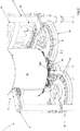
Figure 1 is a perspective view of a machine for filling cartridges for aerosol-generating devices according to the invention; -
Figure 2 is a partial enlarged view ofFigure 1 ; -
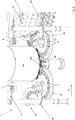
Figure 3 is a front perspective view of the machine ofFigure 1 ; -
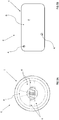
Figure 4A and Figure 4B are two schematic perspective views of two cartridges for aerosol-generating devices of a different type; and -
Figure 5A and Figure 5B are two enlarged top plan views of two cartridges for aerosol-generating devices of a different type. - With reference to
Figures 1-3 , designated by thereference number 1 is a machine for filling cartridges for aerosol-generating devices according to the present invention. As already mentioned previously, the above cartridges C may be used in the pharmaceutical sector (for devices that deliver medicaments) or in the tobacco sector (for electronic cigarettes). - A cartridge C (illustrated in two schematic perspective views in
Figures 4A and 4B , according to two different examples, and in two enlarged top plan views inFigures 5A and 5B , according to two different examples) has an axis H of longitudinal development and a container body B defined by side walls L and by a bottom wall F. Present on the side opposite to the bottom wall F is an end E with an open area A where access into the cartridge C is allowed, and an at least partially occluded area O where access to the inside of the cartridge C is prevented. The axis H of longitudinal development passes through the aforesaid end E and through the bottom wall F. - In particular, by "open area A of the end E" is meant an area of the cartridge C accessible for the purposes of filling, whereas by "at least partially occluded area O" is meant an area where access to the inside of the cartridge C for the purposes of filling is prevented or hindered. In detail, as already anticipated in the introductory part of the present treatment, the at least partially occluded area O may be determined, for example, by the presence of some components V pre-arranged within the cartridge C (for example, as has already been said, an absorbent substrate, a channel for passage of air, a wick with a resistance, etc.). Reference may be made to
Figure 5A , where visible from above is a cartridge C of this type (in particular, a cartridge C for an electronic cigarette), and toFigure 4A , where a schematic perspective view of another cartridge C of this type is represented. - According to a further example, illustrated schematically in
Figure 4B , the at least partially occluded area O may be defined by a wall P of the cartridge C, located at the aforesaid end E, opposite to the bottom wall F. In other words, in this case, the opening of the cartridge C may be set asymmetrically with respect to the longitudinal axis H of the cartridge C itself, and/or may have an irregular profile, or else again one or more open areas A of small dimensions may be present. With reference toFigure 5B , represented, in top plan view, is a cartridge C with a substantially rectangular cross section with two open areas A of small dimensions set asymmetrically with respect to the longitudinal axis H of the cartridge C. - With reference to the attached
Figures 1-3 , thefilling machine 1 according to the invention comprises: afeed line 2, which supplies cartridges C to be filled with their corresponding ends E facing upwards (in particular, with a vertical orientation) in a direction of feed D; and afilling station 3, which receives the cartridges C to be filled that have been supplied and comprises at least one dispensingnozzle 30, which is mobile along a path of forward stroke and is pre-arranged for dispensing a (liquid or powder) product into the cartridge C. - In particular, the
machine 1 comprises first inspection means 4, configured for inspecting the ends E of the cartridges C to be filled in order to identify (or else make it possible to identify), for each cartridge C, the position of the corresponding open area A. With reference to the attachedFigures 1-3 , the first inspection means 4 are arranged above the feed line 2 (i.e., above the cartridges C). - The
machine 1 further comprises anorientation station 5, which receives the cartridges C to be filled that have been inspected and comprises orientation means 50, configured for rotating each cartridge C about its own longitudinal axis H on the basis of the corresponding position identified by the first inspection means 4. The orientation means 50, in detail, are pre-arranged for bringing the open area A of each cartridge C into a position corresponding to a pre-set reference position, for enabling entry of the dispensingnozzle 30 into the open area A of the cartridge C when the dispensingnozzle 30 is driven along the path of forward stroke (and the cartridge C is located in the filling station 3). The orientation means 50 comprise, for example, gripping means 500, described in greater detail in what follows. - In other words, on the basis of the orientation with which the cartridges C are set when they are inspected, i.e., on the basis of the orientation with which the cartridges C are supplied, the orientation means 50 orient each cartridge C, rotating it about its own longitudinal axis H in such a way that, when the cartridge C is in the
filling station 3, the corresponding open area A is aligned to the dispensingnozzle 30, for enabling the latter to enter the cartridge C and fill it with a product. Consequently, whatever the orientation of the cartridges C with respect to the corresponding longitudinal axis H, and whatever the conformation and arrangement of the corresponding open area A, with the present invention, filling of the cartridges C is guaranteed. - The pre-set reference position is the position (for example, with respect to the longitudinal axis H of the cartridge C) in which the open area A of each cartridge C must be arranged for the dispensing
nozzle 30 to be able to enter the cartridge C when the latter is in the filling station 3 (i.e., the position axially aligned to the dispensingnozzle 30 when the dispensingnozzle 30 performs the corresponding forward stroke). - With reference to the attached
Figures 1-3 , theorientation station 5 is set upstream of the filling station 3 (with respect, for example, to a path of the cartridges C in the direction of feed D). - With reference to the attached
Figures 1-3 , the first inspection means 4 are located upstream of the filling station 3 (with respect, for example, to a path of the cartridges C in the direction of feed D). - Preferably, but not exclusively, the first inspection means 4 comprise optical means (for example, a camera).
- The dispensing
nozzle 30 may be constituted by a needle. - During the corresponding forward stroke, the dispensing
nozzle 30 can be moved vertically from above downwards, and then perform a return stroke, in a direction opposite to the forward stroke. Dispensing of the product may occur at the end of the forward stroke of the dispensingnozzle 30, but also immediately after (during the first stretch of the return stroke) and/or immediately before (during the last stretch of the forward stroke). - Preferably, the
filling station 3 comprises a plurality of dispensingnozzles 30, as in the case illustrated. - For instance, the
feed line 2 comprises at least onetransfer device - The
filling machine 1 may comprise a control unit (not illustrated), which is connected to the first inspection means 4 and to theorientation station 5. The control unit receives the information (for example, one or more images) from the first inspection means 4 and processes it for identifying the position of the open area A of each cartridge C (i.e., the orientation of the cartridge C with respect to the corresponding longitudinal axis H). - The control unit may comprise a memory, stored in which is the aforesaid reference position of the open area A of each cartridge C, i.e., as has already been said, the position in which the open area A of each cartridge C must be set for the dispensing
nozzle 30 to be able to enter the cartridge C when the cartridge C is located in thefilling station 3. - The control unit is able to compare the position detected by the first inspection means 4 with the reference position stored in the memory, and, if these two positions do not coincide, drives the orientation means 50 so that they will turn the cartridge C in order to bring the corresponding open area A into the reference position.
- According to the preferred embodiment illustrated in the attached
Figures 1-3 , thefilling machine 1 further comprises: second inspection means 6, configured for inspecting the ends E of the cartridges C to be filled at output from theorientation station 5 in order to identify (or else make it possible to identify), for each cartridge C, the position of the corresponding open area A. With reference to the aforesaid figures, the second inspection means 6 are located downstream of the orientation means 50 (i.e., downstream of theorientation station 5 and upstream of thefilling station 3 with respect to a path of the cartridges C in the direction of feed D) and above the cartridges C (i.e., above the feed line 2). - Preferably, but not exclusively, the second inspection means 6 comprise optical means (for example, a camera).
- The filling
machine 1 may further comprise control means (not illustrated), which, on the basis of the identified position of each cartridge C, drive or inhibit movement of the dispensingnozzle 30 along the path of forward stroke and consequent dispensing of the product. - In other words, a second inspection of the orientation of the cartridges C with respect to the corresponding longitudinal axis H is carried out. Thanks to the control means, movement of the dispensing
nozzle 30 in the corresponding path of forward stroke can be prevented in the case where a cartridge C is not properly oriented for the purposes of filling thereof. In this way, advantageously, there is prevented both impact of the dispensingnozzle 30 on the occluded area O of the end E of the cartridge C, and waste of liquid, which would be dispensed without obtaining filling of the cartridge C and would, instead, dirty thefilling station 3 and the surrounding environment. - The filling
machine 1 may comprise a control unit (not illustrated), which may be the one referred to previously or not and is connected to the second inspection means 6 and to the fillingstation 3. The control unit receives the information (for example, one or more images) from the second inspection means 6 and processes it in order to identify the position of the open area A of each cartridge C. - The control unit may comprise a memory (which may be the one referred to previously or not), stored in which is the aforesaid reference position of the open area A of each cartridge C, as described previously, i.e., the position in which the open area A of each cartridge C must be set for the dispensing
nozzle 30 to be able to enter the cartridge C when the latter is in the fillingstation 3. - The control unit compares the position detected by the second inspection means 6 with the reference position stored in the memory, and, if these positions do not coincide, drives the dispensing
nozzle 30 which is to fill that cartridge C so that it will not perform the corresponding forward stroke (i.e., it inhibits the corresponding movement) and will not deliver the product. Otherwise, i.e., if the detected position and the reference position coincide, the control unit drives the movement of the dispensingnozzle 30; i.e., it enables movement thereof along the corresponding path of forward stroke and dispensing of the product into the cartridge C. - With reference in the attached
Figures 1-3 , the second inspection means 6 are located upstream of the fillingstation 3. - Preferably, with reference to
Figures 1-3 , the fillingstation 3 comprises a plurality of dispensingnozzles 30 and a plurality ofheads 31, eachhead 31 carrying at least one dispensingnozzle 30 for moving it during the corresponding forward stroke. - The filling
station 3 may further comprise release means (not visible in the attached figures), connected to each dispensingnozzle 30 and to the correspondinghead 31. The release means can be activated for automatically releasing each dispensingnozzle 30 from therespective head 31 following upon contact of the dispensingnozzle 30 with the occluded area O of the cartridge C during movement thereof along the path of forward stroke in order to interrupt the forward stroke (and also prevent dispensing of the product). - Advantageously, in this way, impact of the dispensing
nozzle 30 against the occluded area O of the end E of the cartridge C is limited; such impact could cause significant damage to the dispensingnozzle 30 if the latter were, instead, to continue along its path of forward stroke. In addition, useless dispensing of product is prevented, which would constitute a waste and would moreover dirty thefilling station 3. - For instance, the release means comprise elastic means and/or pneumatic means.
- Clearly, the release means may be present together with, or as an alternative to, the control means described previously. In the case where the release means are provided together with the control means described previously, advantageously, they constitute a further solution aimed at preventing in an even more certain way damage to the dispensing
nozzle 30 and undesirable dispensing of the product. In fact, in the case where, even in the presence of second inspection means 6, a dispensingnozzle 30 were to be driven along its path of forward stroke, but the cartridge C were not to have the corresponding open area A set in the reference position (hence in the case either of erroneous driving of the dispensingnozzle 30 or of erroneous inspection of the end E of a cartridge C), damage to the dispensingnozzle 30 and undesirable dispensing of product would in any case be prevented for the reasons described above. - There now follows a detailed description of the path of the cartridges C with reference to the embodiment illustrated.
- With reference to the attached
Figures 1-3 , the cartridges C are conveyed along theentire machine 1 within supporting containers G, also referred to as godets, which are designed for carrying unstable products and/or products of small dimensions. It is clear that the cartridges C, according to a variant not illustrated, can be conveyed, with suitable means, along theentire machine 1 even in the absence of the aforesaid supporting containers G. - Once again with particular reference to what has been illustrated, the
feed line 2 comprises three rotary orstar conveyors orientation station 5, and one 23 being set between theorientation station 5 and the fillingstation 3. It is clear that, as has already been said, the number and type of transfer conveyors may be different. Hence, in the case illustrated, theorientation station 5 is arranged along thefeed line 2. - To return to
Figures 1-3 , thestar conveyors - The cartridges C thus travel along the
first star conveyor 21 and are then transferred to thesecond star conveyor 22, arranged above which the first inspection means 4, in this case comprising acamera 4. Here the cartridges C are inspected as described above. The information detected by thecamera 4 is sent to the control unit (not illustrated), which processes it to identify the position of the open area A of each cartridge C and drive the orientation means 50 accordingly. - The orientation means 50 are arranged in the
orientation station 5, which comprises, for example, arotary turret 51. The orientation means 50 comprisegripping means 500 such as grippers or picker hands (see the detail ofFigure 2 ), which are carried by theturret 51 and, when the cartridges C are in theorientation station 5, are set above the cartridges C. If the detected position of a cartridge C is different from the reference position, the gripping means 500 pick up the cartridge C, and turn it about the corresponding longitudinal axis H, as described previously, to bring the position identified into the reference position. If the two positions already coincide before the cartridges C reach theorientation station 5, the gripping means 500 will not perform any action. - In the
orientation station 5, underneath the gripping means 500, a wheel with vertical axis is provided, which conveys the cartridges C, and is in particular provided with housings for receiving and withholding the cartridges C and the corresponding supporting container G. - At output from the
orientation station 5, the cartridges C in the corresponding supporting containers G reach thethird star conveyor 23, provided on which are the second inspection means 6, which in this case comprise acamera 6. Thethird conveyor 23 advantageously makes it possible to have time and space between theorientation station 5 and the fillingstation 3 to carry out a second inspection of the cartridges C. - Once inspected, the cartridges C enter the filling
station 3. In the case illustrated, the fillingstation 3 is a carousel mobile in rotation about the corresponding vertical central axis, which comprises a plurality ofheads 31, each of which carries a dispensing nozzle 30 (in detail, a needle) and which are arranged so to define a closed circular path. In this case, filling of the cartridges C occurs while the cartridges C are moving. Clearly, the fillingstation 3 may even be of a type different from the one illustrated: for example, the filling station may be of the linear or rotary type, or else may envisage filling of the cartridges while they are in the stationary condition. - Underneath the dispensing
nozzles 30, the fillingstation 3 comprises a wheel with vertical axis, which, by rotating, causes advance of the cartridges C; in detail, the wheel is provided with housings for receiving and withholding the cartridges C and the corresponding supporting container G. - As described previously, the cartridges C may be filled or not, according to whether they are properly oriented or not.
- After passage through the filling
station 3, the cartridges C in the corresponding supporting container G are conveyed towards an output, via the conveying means, not represented in the attached drawings. - The invention moreover regards a method for filling cartridges C for aerosol-generating devices, wherein each cartridge C comprises an end E with an open area A which enables access to the inside of the cartridge C and an occluded area O where access to the inside of the cartridge C is prevented. The cartridge C has an axis H of longitudinal development that passes through the aforesaid end E (for further details on the cartridge C, see the foregoing description).
- The filling method according to the invention may be implemented, preferably, but not exclusively, by the filling
machine 1 described above. - The method according to the invention comprises the step of feeding the cartridges C to be filled with their corresponding ends E facing upwards (preferably with a vertical orientation).
- In particular, following upon the aforesaid step, the method comprises the steps of:
- carrying out a first inspection of the ends E of the cartridges C to be filled in order to identify the position of the corresponding open area A; and then:
- orienting each cartridge C to be filled, rotating it about its own longitudinal axis H on the basis of the identified position, to bring the open area A into a reference position; and
- filling each cartridge C with a product if the corresponding open area A is in the reference position.
- The method according to the invention guarantees filling of the cartridges C whatever the orientation of the cartridges C (with respect to the corresponding longitudinal axis H) during feed thereof (i.e., at the moment of their inspection). Moreover, the method makes it possible to fill any type of cartridge C, as already described previously, whatever the conformation, size, and arrangement of the corresponding open area A with respect to the aforesaid longitudinal axis H and with respect to the end E of the cartridge C (i.e., also in the case of components provided in the cartridge C or of walls that constitute an impediment to access to the inside of the cartridge C).
- Clearly, if the open area A of a cartridge C is already in the pre-set reference position, the cartridge C is not turned about its own longitudinal axis H.
- For instance, the method according to the invention may further comprise the steps of storing in a memory a reference position of the open area A of each cartridge C, i.e., the position in which the open area A of each cartridge C is to be arranged for the filling operation to be successful.
- For instance, the step of orienting each cartridge C to be filled comprises the sub-steps of:
- comparing the effective position of the open area A of each cartridge C that has been detected with the reference position stored in the memory; and, if these do not coincide,
- rotating the cartridge C to bring the corresponding open area A into the reference position.
- Preferably, the method may comprise, following upon the step of orienting each cartridge C to be filled and prior to the filling step, the step of:
- carrying out a second inspection of the ends E of the cartridges C to be filled that have been oriented in order to identify the position of the corresponding open area A.
- In this case, a double check of the ends E of the cartridges C to be filled is carried out.
- Preferably, the step of filling each cartridge C comprises the step of:
- providing (at least) a dispensing
nozzle 30, which is mobile along a path of forward stroke and is able to dispense a (liquid or powder) product, following upon movement thereof. - The dispensing
nozzle 30 may be constituted by a needle, as described above. - Furthermore, following upon the step of providing the dispensing
nozzle 30, the method may comprise the step of: - driving the dispensing
nozzle 30 along the corresponding path of forward stroke (for example, in a vertical direction, as described previously). - As an alternative to what has just been said, following upon the step of providing a dispensing
nozzle 30, the method may comprise the step of: - inhibiting movement of the dispensing
nozzle 30 along the corresponding path of forward stroke and dispensing of the product if the open area A of the cartridge C is not in the reference position. - In this way, advantageously, as has already been said previously, impact of the dispensing
nozzle 30 against the occluded area O of the end E of the cartridge C, which could cause significant damage to the dispensingnozzle 30, is prevented. In addition, useless dispensing of product, which would otherwise constitute a waste and moreover would dirty the surrounding environment, is prevented. - As an alternative to what has been said, the method may comprise, following upon the step of driving the dispensing
nozzle 30, the step of: - interrupting the forward stroke of the dispensing
nozzle 30 if the dispensingnozzle 30 comes into contact with the at least partially occluded area O of the cartridge C during the forward stroke and inhibiting dispensing of the product. - The above step may be carried out, for example, if the second inspection is not successful and the dispensing
nozzle 30 has been driven along its path of forward stroke even if the position of the open area A of a cartridge C does not coincide with the pre-set reference position. - In this way, advantageously, as has already been said previously, any impact of the dispensing
nozzle 30 against the occluded area O of the end E of the cartridge C is limited; such impact could cause significant damage to the dispensingnozzle 30 if the latter were, instead, to continue along its corresponding path of forward stroke. In addition, useless dispensing of product is prevented, which would otherwise constitute a waste and would moreover soil the surrounding environment.
Claims (12)
- A machine (1) for filling cartridges (C) for aerosol-generating devices, wherein: each cartridge (C) comprises an end (E) with an open area (A) where access to the inside of the cartridge (C) is allowed and an at least partially occluded area (O) where access to the inside of the cartridge (C) is prevented, the cartridge (C) having an axis (H) of longitudinal development that passes through said end (E);the filling machine (1) comprising:- a feed line (2), which supplies cartridges (C) to be filled with their corresponding ends (E) facing upwards; and- a filling station (3), which receives the cartridges (C) to be filled and comprises at least one dispensing nozzle (30), which is mobile along a path of forward stroke and is pre-arranged for dispensing a product;said machine (1) being characterized in that it comprises:- first inspection means (4) configured for inspecting the ends (E) of the cartridges (C) to be filled in order to identify, for each one, the position of the corresponding open area (A); and- an orientation station (5), which receives the cartridges (C) to be filled that have been inspected; the orientation station (5) comprises orientation means (50), configured for rotating each cartridge (C) about its own longitudinal axis (H), on the basis of the corresponding identified position, bringing the open area (A) into a position corresponding to a pre-set reference position, for enabling entry of the dispensing nozzle (30) into the open area (A) of the cartridge (C) when the dispensing nozzle (30) is driven along the path of forward stroke.
- The machine (1) according to the preceding claim, further comprising: a control unit, which is connected to the first inspection means (4) and to the orientation station (5) and receives information from the first inspection means (4) and processes it in order to identify the open area (A) of each cartridge (C), the control unit being provided with a memory, stored in which is said reference position, and being able to compare the detected position with the reference position, in order to control the orientation means (50) so that the latter will turn each cartridge (C) in order to bring the corresponding open area (A) into the reference position.
- The machine (1) according to Claim 1 or Claim 2, further comprising:- second inspection means (6), configured for inspecting the ends (E) of the cartridges (C) to be filled at output from the orientation station (5) in order to identify, for each one, the position of the corresponding open area (A); and- control means, which, on the basis of the identified position of each cartridge (C), activate or inhibit movement of the dispensing nozzle (30) along the path of forward stroke and consequent dispensing of the product.
- The machine (1) according to the preceding claim, further comprising a control unit, which is connected to the second inspection means (6) and to the filling station (3) and receives the information from the second inspection means (6) and processes it so as to identify the position of the open area (A) of each cartridge (C), the control unit being provided with a memory, stored in which is said reference position, and being able to compare the position detected by the second inspection means (6) with the reference position stored in the memory in order to drive the dispensing nozzle (30) so that it will perform the corresponding forward stroke or else to inhibit it from performing said forward stroke.
- The machine (1) according to any one of the preceding claims, wherein the filling station (3) comprises a plurality of dispensing nozzles (30) and a plurality of heads (31), each head (31) carrying at least one dispensing nozzle (30) so as to move the latter during the corresponding forward stroke; the filling station (3) further comprising release means, connected to each dispensing nozzle (30) and to the corresponding head (31); the release means being activatable for releasing each dispensing nozzle (30) from the respective head (31) following upon contact of the dispensing nozzle (30) with the occluded area (O) of the cartridge (C) during movement of the dispensing nozzle (30) along the path of forward stroke, in order to interrupt said movement along the path of the forward stroke.
- The machine (1) according to the preceding claim, wherein the release means comprise elastic means or pneumatic means.
- A method for filling cartridges (C) for aerosol-generating devices, wherein each cartridge (C) comprises an end (E) with an open area (A), where access to the inside of the cartridge (C) is allowed, and an at least partially occluded area (O), where access to the inside of the cartridge (C) is prevented, the cartridge (C) having an axis (H) of longitudinal development that passes through said end (E);the method comprising the step of:- feeding the cartridges (C) to be filled with their corresponding ends (E) facing upwards;said method being characterized in that it comprises, in succession, the steps of:- carrying out a first inspection of the ends (E) of the cartridges (C) to be filled in order to identify the position of the corresponding open area (A); and then- orienting each cartridge (C) to be filled, rotating it about its own longitudinal axis (H) on the basis of the position identified, so as to bring the open area (A) into a reference position; and- filling each cartridge (C) with a product if the corresponding open area (A) is in the reference position.
- The method according to the preceding claim, further comprising, prior to the filling step, the step of:- carrying out a second inspection of the ends (E) of the cartridges (C) to be filled that have been oriented in order to identify the position of the corresponding open area (A).
- The method according to Claim 7 or Claim 8, wherein the step of filling each cartridge (C) comprises the step of:- providing a dispensing nozzle (30), which is mobile along a path of forward stroke and is able to dispense a product following upon the corresponding movement.
- The method according to the preceding claim, comprising, following upon the step of providing the dispensing nozzle (30), the step of:- driving the dispensing nozzle (30) along the corresponding path of forward stroke.
- The method according to the preceding claim, further comprising the step of:
interrupting the forward stroke of the dispensing nozzle (30) if the dispensing nozzle (30) contacts the at least partially occluded area (O) of the cartridge (C) during the forward stroke and inhibiting dispensing of the product. - The method according to Claim 9, comprising the step of:- inhibiting movement of the dispensing nozzle (30) along the corresponding path of forward stroke and dispensing the product if the open area (A) of the cartridge (C) is not in the reference position.
Priority Applications (1)
| Application Number | Priority Date | Filing Date | Title |
|---|---|---|---|
| PL18834048T PL3740430T3 (en) | 2018-01-19 | 2018-12-19 | Machine and method for filling cartridges for aerosol-generating devices |
Applications Claiming Priority (2)
| Application Number | Priority Date | Filing Date | Title |
|---|---|---|---|
| IT201800001387A IT201800001387A1 (en) | 2018-01-19 | 2018-01-19 | Machine and method for filling cartridges for aerosol generators |
| PCT/IB2018/060356 WO2019142040A1 (en) | 2018-01-19 | 2018-12-19 | Machine and method for filling cartridges for aerosol-generating devices |
Publications (2)
| Publication Number | Publication Date |
|---|---|
| EP3740430A1 EP3740430A1 (en) | 2020-11-25 |
| EP3740430B1 true EP3740430B1 (en) | 2021-09-01 |
Family
ID=62002263
Family Applications (1)
| Application Number | Title | Priority Date | Filing Date |
|---|---|---|---|
| EP18834048.3A Active EP3740430B1 (en) | 2018-01-19 | 2018-12-19 | Machine and method for filling cartridges for aerosol-generating devices |
Country Status (5)
| Country | Link |
|---|---|
| US (1) | US11365018B2 (en) |
| EP (1) | EP3740430B1 (en) |
| IT (1) | IT201800001387A1 (en) |
| PL (1) | PL3740430T3 (en) |
| WO (1) | WO2019142040A1 (en) |
Families Citing this family (1)
| Publication number | Priority date | Publication date | Assignee | Title |
|---|---|---|---|---|
| US12007334B2 (en) | 2021-10-25 | 2024-06-11 | Applied Materials, Inc. | Compact apparatus for batch vial inspection |
Family Cites Families (5)
| Publication number | Priority date | Publication date | Assignee | Title |
|---|---|---|---|---|
| US5209044A (en) * | 1991-07-11 | 1993-05-11 | Innovative Automation Inc. | Automatic tube filling device and process |
| US9340368B2 (en) * | 2013-07-26 | 2016-05-17 | Ball Corporation | Apparatus and method for orienting a beverage container end closure and applying indicia in a predetermined location |
| WO2015186000A2 (en) * | 2014-04-14 | 2015-12-10 | Altria Client Services Inc. | Method and system for the automated production of e-vapor devices |
| AU2015352059B2 (en) * | 2014-11-27 | 2019-11-21 | Makro Labelling S.R.L. | Machine and method for orienting containers |
| DE102014226965A1 (en) * | 2014-12-23 | 2016-06-23 | Krones Ag | Apparatus and method for the continuous inspection of containers |
-
2018
- 2018-01-19 IT IT201800001387A patent/IT201800001387A1/en unknown
- 2018-12-19 EP EP18834048.3A patent/EP3740430B1/en active Active
- 2018-12-19 PL PL18834048T patent/PL3740430T3/en unknown
- 2018-12-19 WO PCT/IB2018/060356 patent/WO2019142040A1/en not_active Ceased
- 2018-12-19 US US16/962,871 patent/US11365018B2/en active Active
Also Published As
| Publication number | Publication date |
|---|---|
| IT201800001387A1 (en) | 2019-07-19 |
| US20200346791A1 (en) | 2020-11-05 |
| PL3740430T3 (en) | 2022-01-17 |
| US11365018B2 (en) | 2022-06-21 |
| EP3740430A1 (en) | 2020-11-25 |
| WO2019142040A1 (en) | 2019-07-25 |
Similar Documents
| Publication | Publication Date | Title |
|---|---|---|
| US6363687B1 (en) | Secured cell, rapid fill automated tablet order filling system | |
| US6345487B1 (en) | High quality control tablet filler device | |
| US9299211B2 (en) | Tablet feeder | |
| US7878366B2 (en) | Unit for filling containers with products, in particular, pharmaceutical products | |
| US10173830B2 (en) | Medication dispensing container | |
| US5369940A (en) | Automatic filling system | |
| US10017329B2 (en) | Unjamming system for product feeders | |
| JP6372828B2 (en) | Preform alignment device | |
| TR201815702T4 (en) | System for feeding preforms. | |
| CN107108131B (en) | Apparatus and method for reliably supplying compliant closure elements | |
| KR101333495B1 (en) | Medicine discharge device and medicine discharging method using the medicine discharge device | |
| US20110113730A1 (en) | Packaging apparatus for handling pills and associated method | |
| US5564551A (en) | Puck conveying mechanism and method | |
| JP3388935B2 (en) | Drug dispensing method and device | |
| US11365018B2 (en) | Machine and method for filling cartridges for aerosol-generating devices | |
| KR20220136516A (en) | Dispensing canisters for packaging pharmaceuticals via robotic technology | |
| JP2003312780A (en) | Cap feeding device | |
| ITBO980277A1 (en) | ORIENTING GROUP OF LIDS OR BOTTOMS FOR MEDICINAL CAPSULES AND AN ITA FEEDER AND ORIENTER RELATED TO THIS GROUP. | |
| KR101356965B1 (en) | Medicine discharge device and medicine discharging method using the medicine discharge device | |
| JP2002302238A (en) | Flat container supply alignment device | |
| JP2784489B2 (en) | Article alignment machine | |
| JP3876330B2 (en) | Cap feeder | |
| JPH0470069B2 (en) | ||
| KR102046780B1 (en) | Preparation of drugs method for automatic medicine packing machine | |
| JP4742290B2 (en) | Capper cap feeder |
Legal Events
| Date | Code | Title | Description |
|---|---|---|---|
| STAA | Information on the status of an ep patent application or granted ep patent |
Free format text: STATUS: UNKNOWN |
|
| STAA | Information on the status of an ep patent application or granted ep patent |
Free format text: STATUS: THE INTERNATIONAL PUBLICATION HAS BEEN MADE |
|
| PUAI | Public reference made under article 153(3) epc to a published international application that has entered the european phase |
Free format text: ORIGINAL CODE: 0009012 |
|
| STAA | Information on the status of an ep patent application or granted ep patent |
Free format text: STATUS: REQUEST FOR EXAMINATION WAS MADE |
|
| 17P | Request for examination filed |
Effective date: 20200714 |
|
| AK | Designated contracting states |
Kind code of ref document: A1 Designated state(s): AL AT BE BG CH CY CZ DE DK EE ES FI FR GB GR HR HU IE IS IT LI LT LU LV MC MK MT NL NO PL PT RO RS SE SI SK SM TR |
|
| AX | Request for extension of the european patent |
Extension state: BA ME |
|
| DAV | Request for validation of the european patent (deleted) | ||
| DAX | Request for extension of the european patent (deleted) | ||
| GRAP | Despatch of communication of intention to grant a patent |
Free format text: ORIGINAL CODE: EPIDOSNIGR1 |
|
| STAA | Information on the status of an ep patent application or granted ep patent |
Free format text: STATUS: GRANT OF PATENT IS INTENDED |
|
| INTG | Intention to grant announced |
Effective date: 20210514 |
|
| GRAS | Grant fee paid |
Free format text: ORIGINAL CODE: EPIDOSNIGR3 |
|
| GRAA | (expected) grant |
Free format text: ORIGINAL CODE: 0009210 |
|
| STAA | Information on the status of an ep patent application or granted ep patent |
Free format text: STATUS: THE PATENT HAS BEEN GRANTED |
|
| AK | Designated contracting states |
Kind code of ref document: B1 Designated state(s): AL AT BE BG CH CY CZ DE DK EE ES FI FR GB GR HR HU IE IS IT LI LT LU LV MC MK MT NL NO PL PT RO RS SE SI SK SM TR |
|
| REG | Reference to a national code |
Ref country code: GB Ref legal event code: FG4D |
|
| REG | Reference to a national code |
Ref country code: CH Ref legal event code: EP Ref country code: AT Ref legal event code: REF Ref document number: 1426010 Country of ref document: AT Kind code of ref document: T Effective date: 20210915 |
|
| REG | Reference to a national code |
Ref country code: DE Ref legal event code: R096 Ref document number: 602018023052 Country of ref document: DE |
|
| REG | Reference to a national code |
Ref country code: IE Ref legal event code: FG4D Ref country code: NL Ref legal event code: FP |
|
| REG | Reference to a national code |
Ref country code: LT Ref legal event code: MG9D |
|
| PG25 | Lapsed in a contracting state [announced via postgrant information from national office to epo] |
Ref country code: RS Free format text: LAPSE BECAUSE OF FAILURE TO SUBMIT A TRANSLATION OF THE DESCRIPTION OR TO PAY THE FEE WITHIN THE PRESCRIBED TIME-LIMIT Effective date: 20210901 Ref country code: SE Free format text: LAPSE BECAUSE OF FAILURE TO SUBMIT A TRANSLATION OF THE DESCRIPTION OR TO PAY THE FEE WITHIN THE PRESCRIBED TIME-LIMIT Effective date: 20210901 Ref country code: ES Free format text: LAPSE BECAUSE OF FAILURE TO SUBMIT A TRANSLATION OF THE DESCRIPTION OR TO PAY THE FEE WITHIN THE PRESCRIBED TIME-LIMIT Effective date: 20210901 Ref country code: FI Free format text: LAPSE BECAUSE OF FAILURE TO SUBMIT A TRANSLATION OF THE DESCRIPTION OR TO PAY THE FEE WITHIN THE PRESCRIBED TIME-LIMIT Effective date: 20210901 Ref country code: BG Free format text: LAPSE BECAUSE OF FAILURE TO SUBMIT A TRANSLATION OF THE DESCRIPTION OR TO PAY THE FEE WITHIN THE PRESCRIBED TIME-LIMIT Effective date: 20211201 Ref country code: LT Free format text: LAPSE BECAUSE OF FAILURE TO SUBMIT A TRANSLATION OF THE DESCRIPTION OR TO PAY THE FEE WITHIN THE PRESCRIBED TIME-LIMIT Effective date: 20210901 Ref country code: NO Free format text: LAPSE BECAUSE OF FAILURE TO SUBMIT A TRANSLATION OF THE DESCRIPTION OR TO PAY THE FEE WITHIN THE PRESCRIBED TIME-LIMIT Effective date: 20211201 Ref country code: HR Free format text: LAPSE BECAUSE OF FAILURE TO SUBMIT A TRANSLATION OF THE DESCRIPTION OR TO PAY THE FEE WITHIN THE PRESCRIBED TIME-LIMIT Effective date: 20210901 |
|
| REG | Reference to a national code |
Ref country code: AT Ref legal event code: MK05 Ref document number: 1426010 Country of ref document: AT Kind code of ref document: T Effective date: 20210901 |
|
| PG25 | Lapsed in a contracting state [announced via postgrant information from national office to epo] |
Ref country code: LV Free format text: LAPSE BECAUSE OF FAILURE TO SUBMIT A TRANSLATION OF THE DESCRIPTION OR TO PAY THE FEE WITHIN THE PRESCRIBED TIME-LIMIT Effective date: 20210901 Ref country code: GR Free format text: LAPSE BECAUSE OF FAILURE TO SUBMIT A TRANSLATION OF THE DESCRIPTION OR TO PAY THE FEE WITHIN THE PRESCRIBED TIME-LIMIT Effective date: 20211202 |
|
| PG25 | Lapsed in a contracting state [announced via postgrant information from national office to epo] |
Ref country code: AT Free format text: LAPSE BECAUSE OF FAILURE TO SUBMIT A TRANSLATION OF THE DESCRIPTION OR TO PAY THE FEE WITHIN THE PRESCRIBED TIME-LIMIT Effective date: 20210901 |
|
| PG25 | Lapsed in a contracting state [announced via postgrant information from national office to epo] |
Ref country code: IS Free format text: LAPSE BECAUSE OF FAILURE TO SUBMIT A TRANSLATION OF THE DESCRIPTION OR TO PAY THE FEE WITHIN THE PRESCRIBED TIME-LIMIT Effective date: 20220101 Ref country code: SM Free format text: LAPSE BECAUSE OF FAILURE TO SUBMIT A TRANSLATION OF THE DESCRIPTION OR TO PAY THE FEE WITHIN THE PRESCRIBED TIME-LIMIT Effective date: 20210901 Ref country code: SK Free format text: LAPSE BECAUSE OF FAILURE TO SUBMIT A TRANSLATION OF THE DESCRIPTION OR TO PAY THE FEE WITHIN THE PRESCRIBED TIME-LIMIT Effective date: 20210901 Ref country code: RO Free format text: LAPSE BECAUSE OF FAILURE TO SUBMIT A TRANSLATION OF THE DESCRIPTION OR TO PAY THE FEE WITHIN THE PRESCRIBED TIME-LIMIT Effective date: 20210901 Ref country code: PT Free format text: LAPSE BECAUSE OF FAILURE TO SUBMIT A TRANSLATION OF THE DESCRIPTION OR TO PAY THE FEE WITHIN THE PRESCRIBED TIME-LIMIT Effective date: 20220103 Ref country code: EE Free format text: LAPSE BECAUSE OF FAILURE TO SUBMIT A TRANSLATION OF THE DESCRIPTION OR TO PAY THE FEE WITHIN THE PRESCRIBED TIME-LIMIT Effective date: 20210901 Ref country code: CZ Free format text: LAPSE BECAUSE OF FAILURE TO SUBMIT A TRANSLATION OF THE DESCRIPTION OR TO PAY THE FEE WITHIN THE PRESCRIBED TIME-LIMIT Effective date: 20210901 Ref country code: AL Free format text: LAPSE BECAUSE OF FAILURE TO SUBMIT A TRANSLATION OF THE DESCRIPTION OR TO PAY THE FEE WITHIN THE PRESCRIBED TIME-LIMIT Effective date: 20210901 |
|
| REG | Reference to a national code |
Ref country code: DE Ref legal event code: R097 Ref document number: 602018023052 Country of ref document: DE |
|
| PLBE | No opposition filed within time limit |
Free format text: ORIGINAL CODE: 0009261 |
|
| STAA | Information on the status of an ep patent application or granted ep patent |
Free format text: STATUS: NO OPPOSITION FILED WITHIN TIME LIMIT |
|
| PG25 | Lapsed in a contracting state [announced via postgrant information from national office to epo] |
Ref country code: MC Free format text: LAPSE BECAUSE OF FAILURE TO SUBMIT A TRANSLATION OF THE DESCRIPTION OR TO PAY THE FEE WITHIN THE PRESCRIBED TIME-LIMIT Effective date: 20210901 Ref country code: IT Free format text: LAPSE BECAUSE OF FAILURE TO SUBMIT A TRANSLATION OF THE DESCRIPTION OR TO PAY THE FEE WITHIN THE PRESCRIBED TIME-LIMIT Effective date: 20210901 Ref country code: DK Free format text: LAPSE BECAUSE OF FAILURE TO SUBMIT A TRANSLATION OF THE DESCRIPTION OR TO PAY THE FEE WITHIN THE PRESCRIBED TIME-LIMIT Effective date: 20210901 |
|
| REG | Reference to a national code |
Ref country code: CH Ref legal event code: PL |
|
| 26N | No opposition filed |
Effective date: 20220602 |
|
| REG | Reference to a national code |
Ref country code: BE Ref legal event code: MM Effective date: 20211231 |
|
| PG25 | Lapsed in a contracting state [announced via postgrant information from national office to epo] |
Ref country code: LU Free format text: LAPSE BECAUSE OF NON-PAYMENT OF DUE FEES Effective date: 20211219 Ref country code: IE Free format text: LAPSE BECAUSE OF NON-PAYMENT OF DUE FEES Effective date: 20211219 |
|
| PG25 | Lapsed in a contracting state [announced via postgrant information from national office to epo] |
Ref country code: FR Free format text: LAPSE BECAUSE OF NON-PAYMENT OF DUE FEES Effective date: 20211231 Ref country code: BE Free format text: LAPSE BECAUSE OF NON-PAYMENT OF DUE FEES Effective date: 20211231 |
|
| PG25 | Lapsed in a contracting state [announced via postgrant information from national office to epo] |
Ref country code: LI Free format text: LAPSE BECAUSE OF NON-PAYMENT OF DUE FEES Effective date: 20211231 Ref country code: CH Free format text: LAPSE BECAUSE OF NON-PAYMENT OF DUE FEES Effective date: 20211231 |
|
| P01 | Opt-out of the competence of the unified patent court (upc) registered |
Effective date: 20230524 |
|
| PG25 | Lapsed in a contracting state [announced via postgrant information from national office to epo] |
Ref country code: CY Free format text: LAPSE BECAUSE OF FAILURE TO SUBMIT A TRANSLATION OF THE DESCRIPTION OR TO PAY THE FEE WITHIN THE PRESCRIBED TIME-LIMIT Effective date: 20210901 |
|
| PG25 | Lapsed in a contracting state [announced via postgrant information from national office to epo] |
Ref country code: HU Free format text: LAPSE BECAUSE OF FAILURE TO SUBMIT A TRANSLATION OF THE DESCRIPTION OR TO PAY THE FEE WITHIN THE PRESCRIBED TIME-LIMIT; INVALID AB INITIO Effective date: 20181219 |
|
| GBPC | Gb: european patent ceased through non-payment of renewal fee |
Effective date: 20221219 |
|
| PG25 | Lapsed in a contracting state [announced via postgrant information from national office to epo] |
Ref country code: SI Free format text: LAPSE BECAUSE OF FAILURE TO SUBMIT A TRANSLATION OF THE DESCRIPTION OR TO PAY THE FEE WITHIN THE PRESCRIBED TIME-LIMIT Effective date: 20210901 |
|
| PG25 | Lapsed in a contracting state [announced via postgrant information from national office to epo] |
Ref country code: GB Free format text: LAPSE BECAUSE OF NON-PAYMENT OF DUE FEES Effective date: 20221219 |
|
| PG25 | Lapsed in a contracting state [announced via postgrant information from national office to epo] |
Ref country code: MK Free format text: LAPSE BECAUSE OF FAILURE TO SUBMIT A TRANSLATION OF THE DESCRIPTION OR TO PAY THE FEE WITHIN THE PRESCRIBED TIME-LIMIT Effective date: 20210901 |
|
| PG25 | Lapsed in a contracting state [announced via postgrant information from national office to epo] |
Ref country code: MT Free format text: LAPSE BECAUSE OF FAILURE TO SUBMIT A TRANSLATION OF THE DESCRIPTION OR TO PAY THE FEE WITHIN THE PRESCRIBED TIME-LIMIT Effective date: 20210901 |
|
| PG25 | Lapsed in a contracting state [announced via postgrant information from national office to epo] |
Ref country code: TR Free format text: LAPSE BECAUSE OF FAILURE TO SUBMIT A TRANSLATION OF THE DESCRIPTION OR TO PAY THE FEE WITHIN THE PRESCRIBED TIME-LIMIT Effective date: 20210901 |
|
| PGFP | Annual fee paid to national office [announced via postgrant information from national office to epo] |
Ref country code: NL Payment date: 20251226 Year of fee payment: 8 |
|
| PGFP | Annual fee paid to national office [announced via postgrant information from national office to epo] |
Ref country code: PL Payment date: 20251209 Year of fee payment: 8 |
|
| PGFP | Annual fee paid to national office [announced via postgrant information from national office to epo] |
Ref country code: DE Payment date: 20251229 Year of fee payment: 8 |