EP3740387B1 - Verfahren zur herstellung eines transponders für einen fahrzeugreifen - Google Patents
Verfahren zur herstellung eines transponders für einen fahrzeugreifen Download PDFInfo
- Publication number
- EP3740387B1 EP3740387B1 EP18800479.0A EP18800479A EP3740387B1 EP 3740387 B1 EP3740387 B1 EP 3740387B1 EP 18800479 A EP18800479 A EP 18800479A EP 3740387 B1 EP3740387 B1 EP 3740387B1
- Authority
- EP
- European Patent Office
- Prior art keywords
- transponder
- tyre
- antenna
- flat antenna
- tire
- Prior art date
- Legal status (The legal status is an assumption and is not a legal conclusion. Google has not performed a legal analysis and makes no representation as to the accuracy of the status listed.)
- Active
Links
Images
Classifications
-
- B—PERFORMING OPERATIONS; TRANSPORTING
- B60—VEHICLES IN GENERAL
- B60C—VEHICLE TYRES; TYRE INFLATION; TYRE CHANGING; CONNECTING VALVES TO INFLATABLE ELASTIC BODIES IN GENERAL; DEVICES OR ARRANGEMENTS RELATED TO TYRES
- B60C23/00—Devices for measuring, signalling, controlling, or distributing tyre pressure or temperature, specially adapted for mounting on vehicles; Arrangement of tyre inflating devices on vehicles, e.g. of pumps or of tanks; Tyre cooling arrangements
- B60C23/02—Signalling devices actuated by tyre pressure
- B60C23/04—Signalling devices actuated by tyre pressure mounted on the wheel or tyre
- B60C23/0408—Signalling devices actuated by tyre pressure mounted on the wheel or tyre transmitting the signals by non-mechanical means from the wheel or tyre to a vehicle body mounted receiver
- B60C23/0422—Signalling devices actuated by tyre pressure mounted on the wheel or tyre transmitting the signals by non-mechanical means from the wheel or tyre to a vehicle body mounted receiver characterised by the type of signal transmission means
- B60C23/0433—Radio signals
- B60C23/0447—Wheel or tyre mounted circuits
- B60C23/0452—Antenna structure, control or arrangement
-
- G—PHYSICS
- G06—COMPUTING OR CALCULATING; COUNTING
- G06K—GRAPHICAL DATA READING; PRESENTATION OF DATA; RECORD CARRIERS; HANDLING RECORD CARRIERS
- G06K19/00—Record carriers for use with machines and with at least a part designed to carry digital markings
- G06K19/06—Record carriers for use with machines and with at least a part designed to carry digital markings characterised by the kind of the digital marking, e.g. shape, nature, code
- G06K19/067—Record carriers with conductive marks, printed circuits or semiconductor circuit elements, e.g. credit or identity cards also with resonating or responding marks without active components
- G06K19/07—Record carriers with conductive marks, printed circuits or semiconductor circuit elements, e.g. credit or identity cards also with resonating or responding marks without active components with integrated circuit chips
- G06K19/077—Constructional details, e.g. mounting of circuits in the carrier
- G06K19/07749—Constructional details, e.g. mounting of circuits in the carrier the record carrier being capable of non-contact communication, e.g. constructional details of the antenna of a non-contact smart card
- G06K19/07758—Constructional details, e.g. mounting of circuits in the carrier the record carrier being capable of non-contact communication, e.g. constructional details of the antenna of a non-contact smart card arrangements for adhering the record carrier to further objects or living beings, functioning as an identification tag
- G06K19/07764—Constructional details, e.g. mounting of circuits in the carrier the record carrier being capable of non-contact communication, e.g. constructional details of the antenna of a non-contact smart card arrangements for adhering the record carrier to further objects or living beings, functioning as an identification tag the adhering arrangement making the record carrier attachable to a tyre
-
- H—ELECTRICITY
- H01—ELECTRIC ELEMENTS
- H01Q—ANTENNAS, i.e. RADIO AERIALS
- H01Q1/00—Details of, or arrangements associated with, antennas
- H01Q1/12—Supports; Mounting means
- H01Q1/22—Supports; Mounting means by structural association with other equipment or articles
- H01Q1/2208—Supports; Mounting means by structural association with other equipment or articles associated with components used in interrogation type services, i.e. in systems for information exchange between an interrogator/reader and a tag/transponder, e.g. in Radio Frequency Identification [RFID] systems
- H01Q1/2225—Supports; Mounting means by structural association with other equipment or articles associated with components used in interrogation type services, i.e. in systems for information exchange between an interrogator/reader and a tag/transponder, e.g. in Radio Frequency Identification [RFID] systems used in active tags, i.e. provided with its own power source or in passive tags, i.e. deriving power from RF signal
-
- H—ELECTRICITY
- H01—ELECTRIC ELEMENTS
- H01Q—ANTENNAS, i.e. RADIO AERIALS
- H01Q1/00—Details of, or arrangements associated with, antennas
- H01Q1/12—Supports; Mounting means
- H01Q1/22—Supports; Mounting means by structural association with other equipment or articles
- H01Q1/2208—Supports; Mounting means by structural association with other equipment or articles associated with components used in interrogation type services, i.e. in systems for information exchange between an interrogator/reader and a tag/transponder, e.g. in Radio Frequency Identification [RFID] systems
- H01Q1/2241—Supports; Mounting means by structural association with other equipment or articles associated with components used in interrogation type services, i.e. in systems for information exchange between an interrogator/reader and a tag/transponder, e.g. in Radio Frequency Identification [RFID] systems used in or for vehicle tyres
-
- H—ELECTRICITY
- H01—ELECTRIC ELEMENTS
- H01Q—ANTENNAS, i.e. RADIO AERIALS
- H01Q1/00—Details of, or arrangements associated with, antennas
- H01Q1/36—Structural form of radiating elements, e.g. cone, spiral, umbrella; Particular materials used therewith
-
- H—ELECTRICITY
- H01—ELECTRIC ELEMENTS
- H01Q—ANTENNAS, i.e. RADIO AERIALS
- H01Q9/00—Electrically-short antennas having dimensions not more than twice the operating wavelength and consisting of conductive active radiating elements
- H01Q9/04—Resonant antennas
- H01Q9/16—Resonant antennas with feed intermediate between the extremities of the antenna, e.g. centre-fed dipole
- H01Q9/28—Conical, cylindrical, cage, strip, gauze, or like elements having an extended radiating surface; Elements comprising two conical surfaces having collinear axes and adjacent apices and fed by two-conductor transmission lines
- H01Q9/285—Planar dipole
Definitions
- the invention relates to a method for producing a transponder for a vehicle tire.
- the US 2017/358839 A1 , WO 03/105511 A1 , WO 2008/132287 A1 and US 4 911 217 A reveal RFID tags, which are used to identify tires or tire parts.
- the US 2017 / 270401 A1 discloses the use of RFID tags, but for the identification of clothing or laundry items.
- the invention is based on the object of improving the arrangement of transponders on vehicle tires.
- the tire component can be, for example, a component that is intended as a material layer for the tire bead.
- flat antennas are easy to manufacture and are particularly well suited for use with vehicle tires.
- the flat structure of the flat antennas in particular means that they can be easily arranged between tire components, for example in the tire bead.
- the flat antennas also have a high level of durability in relation to the tire deformations that occur when the vehicle tire rolls on a road.
- the thin metal plate consists of brass or brass alloy.
- Flat antennas made of brass or a brass alloy can be connected particularly well to the rubber material of the tire components. This effectively prevents air pockets between the transponder and individual tire components.
- the metal plate in step a) has a material thickness of less than 1 mm.
- This very thin design of the flat antenna makes it easy to connect the transponder to an adjacent tire component. It also prevents tire components from being damaged.
- the surfaces of the transponder are provided with an adhesion promoter.
- the bonding agent creates an optimal connection between the tire components and the transponder. This prevents air pockets between the transponder and the adjacent tire components.
- the adhesion promoter is applied to the transponder using a dipping process or a brushing process.
- step b) the antenna is formed using a punching process.
- step b) the forming of the antenna is carried out by laser beam cutting or water jet cutting.
- the flat antennas can be manufactured with a high degree of precision.
- the flat antenna has a rectangular contour, a meandering contour or a triangular contour.
- These antenna shapes or antenna contours can be manufactured particularly quickly and easily. In addition, these antenna contours ensure optimal transmission quality to the transmitting and receiving unit.
- step c) the flat antenna is connected to the transponder chip with a soldered connection. This makes it possible to achieve a high-strength connection between the transponder chip and the flat antennas.
- step c) the flat antenna is inductively connected to the transponder chip.
- step d) the application of the transponder to the tire component is integrated into the manufacturing process for producing the tire component in the form of preliminary material.
- the transponder is arranged in the region of the tire bead.
- the tire bead is particularly suitable for placing transponders because the permanent load in this area of the vehicle tire is relatively low.
- the transponder can also be located in the sidewall or in the tread area.
- the height dimension in the radial direction of the vehicle tire between the transponder and the upper tip of the bead filler is at least 5 mm.
- the transponder is arranged in an area of the tire bead in which the mechanical stress during driving of the vehicle tire is relatively low.
- the transponder is arranged on the outside of the core filler facing the side wall. This allows a simple radio connection with a high signal quality to be established from the outside to the transponder.
- the transponder is aligned with its two antenna parts in the circumferential direction to the tire core. This gives the transponder an optimal alignment in the tire bead in order to ensure optimal transmission and reception performance.
- the transponder has a width between 3 and 15 mm and a length between 30 and 80 mm.
- the transponder With these dimensions of the transponder, it can be easily arranged between the tire components.
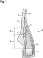
- the Figure 1 shows a schematic cross-section of a tire bead 8.
- the transponder 1 is arranged in the tire bead 8.
- the transponder can also be arranged at other locations in the vehicle tire. Other preferred positions for transponders are areas of the sidewall, areas of the tread or areas in the belt layer of the vehicle tire.
- the transponder 1 is arranged in the tire bead, e.g. between the bead filler 5 and the outer layer turn-up 17 of the carcass layer 6.
- the carcass layer 6 forms a layer turn-up 17 in the tire bead 8, which is guided around the bead filler 5 and the tire core 4.
- the tire core 4 comprises a large number of wire cores and therefore has a very high material stiffness. Due to this material stiffness of the tire core, the transponder is arranged in a particularly calm material zone of the vehicle tire, which is only exposed to low material loads.
- the transponder 1 is arranged between the rubber layer 9 and the layer cover 9.
- the height 18 between the transponder 1 and the underside of the core rider 5 is at least 3 mm, preferably at least 5 mm or at least 7 mm. The higher positioning of the transponder 1 enables better signal transmission to the receiving device.
- the height 19 between the transponder 1 and the tip of the apex 5 is at least 5 mm, preferably at least 7 mm or at least 9 mm.
- the transponder data can therefore be easily read using an external reader.
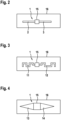
- the Fig. 2 shows the transponder 1 as it is arranged on a tire component.
- the transponder 1 and the tire component 16 are shown in a top view.
- the transponder 1 comprises two rectangular flat antennas 2 and 3.
- the flat antennas are manufactured in a separate manufacturing process. For example, they are produced from a thin metal plate using a punching process. After the two flat antennas have been assembled, they are connected to the transponder chip 15. In this way, a transponder with a dipole antenna is formed.
- connection of the two flat antennas to the transponder chip 15 can be carried out, for example, using a soldering process.
- the flat antennas are made of brass or a brass alloy. This ensures an optimal connection to the tire component 16.
- the tire component 16 can be, for example, a carcass ply or a tire component for a tire bead.
- the transponder 1 is preferably placed on the tire component 16 during the production of the raw material. After the vehicle tire has been manufactured, the transponder 1 is arranged between individual tire components. A possible arrangement of the transponder 1 is shown in the Fig. 1 .
- the Fig. 3 shows a further embodiment -
- the flat antennas 11 and 12 are designed with a meandering contour.
- the Fig. 4 shows another embodiment.
- the transponder 1 has two flat antennas 13 and 14 with a triangular contour.
- the transponder 1 is placed directly on the underlying Tire component 16 is arranged.
- the length of the transponder is between 30 and 90 mm.
- the material thickness of the flat antennas is a maximum of 1 mm.
- the flat antennas have a material thickness of less than 0.5 mm.
Landscapes
- Engineering & Computer Science (AREA)
- Computer Hardware Design (AREA)
- Microelectronics & Electronic Packaging (AREA)
- Physics & Mathematics (AREA)
- General Physics & Mathematics (AREA)
- Theoretical Computer Science (AREA)
- Mechanical Engineering (AREA)
- Tires In General (AREA)
- Support Of Aerials (AREA)
Description
- Die Erfindung betrifft ein Verfahren zur Herstellung eines Transponders für einen Fahrzeugreifen.
- Es ist bekannt, Fahrzeugreifen mit Transpondern zu versehen.
- Aus dem Stand der Technik sind unterschiedliche Konzepte bekannt, Transponder am Reifen anzuordnen. Alle herkömmlichen Konzepte besitzen unterschiedliche Nachteile.
- Die
US 2017/358839 A1 ,WO 03/105511 A1 WO 2008/132287 A1 undUS 4 911 217 A offenbaren RFID Tags, welche zur Identifizierung von Reifen oder Reifenteilen verwendet werden. Auch dieUS 2017 / 270401 A1 offenbart die Verwendung von RFID Tags, jedoch zur Identifizierung von Kleidungs- bzw. Wäscheteilen. - Der Erfindung liegt die Aufgabe zugrunde, das Anordnen von Transpondern an Fahrzeugreifen zu verbessern.
- Gelöst wird die Aufgabe gemäß einem Verfahren mit den folgenden Schritten:
- a) Bereitstellen einer dünnen Metallplatte,
- b) Herstellen von mindestens einer Flachantenne,
wobei die Flachantenne aus der Metallplatte geformt wird, - c) Verbinden der Flachantenne mit einem Transponder-Chip,
wobei der Transponder aus Flachantenne und Transponder-Chip gebildet wird, - d) Herstellen eines Fahrzeugreifens,
- wobei der Transponder mit der Flachantenne bei der Herstellung eines Reifenrohlings auf ein Reifenbauteil aufgebracht wird,
- wobei der Transponder zwischen zwei Reifenbauteilen eingebettet wird,
- e) Fertigstellen des Fahrzeugreifen mit weiteren Schritten.
- Ein Vorteil der Erfindung ist insbesondere darin zu sehen, dass auf diese Weise Transponder im Fahrzeugreifen auf einfache Weise angeordnet werden können. Bei dem Reifenbauteil kann es sich beispielsweise um ein Bauteil handeln, welches als eine Materiallage für den Reifenwulst vorgesehen ist.
- Ein weiterer Vorteil von Flachantennen besteht darin, dass sie sich einfach herstellen lassen und sich besonders gut für den Einsatz für Fahrzeugreifen eignen. Insbesondere durch die flache Struktur der Flachantennen lassen sie sich einfach zwischen Reifenbauteilen beispielsweise im Reifenwulst anordnen. Die Flachantennen besitzen außerdem eine hohe Dauerhaltbarkeit in Bezug auf die Reifendeformationen, die beim Abrollen des Fahrzeugreifens auf einer Fahrbahn auftreten.
- Erfindungsgemäß ist vorgesehen, dass bei Schritt a) die dünne Metallplatte aus Messing oder Messinglegierung besteht.
- Flachantennen aus Messing bzw. aus einer Messinglegierung lassen sich besonders gut mit dem Gummimaterial der Reifenbauteile verbinden. Dadurch lassen sich Lufteinschlüsse zwischen dem Transponder und einzelnen Reifenbauteilen effektiv verhindern.
- Erfindungsgemäß ist vorgesehen, dass bei Schritt a) die Metallplatte eine Materialdicke von kleiner als 1 mm aufweist.
- Durch diese sehr dünne Ausgestaltung der Flachantenne lässt sich der Transponder einfach mit einem anliegenden Reifenbauteil verbinden. Außerdem wird dadurch verhindert, dass Reifenbauteile beschädigt werden können.
- Erfindungsgemäß ist vorgesehen, dass nach Schritt c) die Oberflächen des Transponders mit einem Haftvermittler versehen werden.
- Der Haftvermittler bewirkt eine optimale Verbindung zwischen den Reifenbauteilen und dem Transponder. Auf diese Weise werden insbesondere Lufteinschlüsse zwischen dem Transponder und den anliegenden Reifenbauteilen verhindert.
- In einer weiteren vorteilhaften Weiterbildung der Erfindung ist vorgesehen, dass der Haftvermittler mit einem Tauchverfahren oder einem Aufstreich-Verfahren auf den Transponder aufgebracht wird.
- Durch diese beiden Verfahren lässt sich der Haftvermittler mit einer hohen Geschwindigkeit auf den Transponder aufbringen.
- Erfindungsgemäß ist vorgesehen, dass bei Schritt b) das Formen der Antenne mit einem Stanzprozess erfolgt.
- Dadurch können die einzelnen Flachantennen mit einer hohen Geschwindigkeit und mit einer hohen Genauigkeit hergestellt werden.
- In einer erfindungsgemäßen Alternative ist vorgesehen, dass bei Schritt b) das Formen der Antenne mit einem Laserstrahlschneiden oder einem Wasserstrahlschneiden erfolgt.
- Mit diesen beiden Herstellverfahren können die Flachantennen mit einer hohen Präzision gefertigt werden.
- In einer weiteren vorteilhaften Weiterbildung der Erfindung ist vorgesehen, dass nach Schritt b) die Flachantenne eine rechteckige Kontur, eine mäanderförmige Kontur oder eine dreieckförmige Kontur aufweist.
- Diese Antennenformen bzw. Antennenkonturen lassen sich besonders einfach und schnell herstellen. Außerdem gewährleisten diese Antennenkonturen eine optimale Übertragungsqualität zur Sende- und Empfangseinheit.
- In einer weiteren vorteilhaften Weiterbildung der Erfindung ist vorgesehen, dass bei Schritt c) die Flachantenne mit einer Lötverbindung mit dem Transponder-Chip verbunden wird. Dadurch lässt sich eine hochfeste Verbindung zwischen dem Transponderchip und den Flachantennen erreichen.
- In einer weiteren vorteilhaften Weiterbildung der Erfindung ist vorgesehen, dass bei Schritt c) die Flachantenne induktiv mit dem Transponder-Chip verbunden wird.
- Dadruch lässt sich der Transponderchip einfach und schnell mit den beiden anliegenden Flachantennen verbinden.
- In einer weiteren vorteilhaften Weiterbildung der Erfindung ist vorgesehen, dass bei Schritt d) das Aufbringen des Transponders auf das Reifenbauteil in den Herstellungsprozeß zur Herstellung des Reifenbauteiles in Form von Vormaterial integriert ist.
- Dadurch wird die Zykluszeit an den Reifenbaumaschinen bzw. an den Reifenbautrommeln nicht beeinträchtigt.
- In einer weiteren vorteilhaften Weiterbildung der Erfindung ist vorgesehen, dass der Transponder im Bereich des Reifenwulstes angeordnet ist.
- Der Reifenwulst eignet sich besonders für die Platzierung von Transpondern, weil die Dauerbelastung in diesem Bereich des Fahrzeugreifens relativ gering ist. Der Transponder kann jedoch auch in der Seitenwand oder im Bereich des Laufstreifens angeordnet sein.
- In einer vorteilhaften Weiterbildung der Erfindung ist vorgesehen, dass die Höhenabmessung in radialer Richtung des Fahrzeugreifens zwischen dem Transponder und der oberen Spitze des Kernreiters mindestens 5 mm beträgt.
- Dadurch ist der Transponder in einem Bereich des Reifenwulstes angeordnet in dem die mechanische Beanspruchung im Fahrbetrieb des Fahrzeugreifens relativ gering ist.
- In einer weiteren vorteilhaften Weiterbildung der Erfindung ist vorgesehen, dass der Transponder auf der zur Seitenwand gerichteten Außenseite des Kernreiters angeordnet ist. Dadurch läßt sich von außen eine einfache Funkverbindung mit einer hohen Signalqualität zum Transponder realisieren.
- In einer vorteilhaften Weiterbildung der Erfindung ist vorgesehen, dass der Transponder mit seinen beiden Antennenteilen in Umfangsrichtung zum Reifenkern ausgerichtet ist. Dadurch besitzt der Transponder eine optimale Ausrichtung im Reifenwulst, um eine optimale Sende- und Empfangsleistung zu gewährleisten.
- In einer weiteren vorteilhaften Weiterbildung der Erfindung ist vorgesehen, dass der Transponder eine Breite zwischen 3 und 15 mm sowie eine Länge zwischen 30 und 80 mm aufweist.
- Bei diesen Abmessungen des Transponders lässt sich dieser auf einfache Weise zwischen den Reifenbauteilen anordnen.
- Anhand mehrerer Ausführungsbeispiele soll die Erfindung näher erläutert werden. Es zeigen:
- Fig. 1:
- einen Reifenwulst
- Fig. 2:
- einen Transponder mit zwei rechteckförmigen Flachantennen
- Fig. 3:
- einen Transponder mit zwei mäanderförmigen Flachantennen
- Fig. 4:
- einen Transponder mit zwei dreieckförmigen Flachantennen
- Die
Figur 1 zeigt schematisch den Querschnitt eines Reifenwulstes 8. Bei diesem Ausführungsbeispiel ist der Transponder 1 im Reifenwulst 8 angeordnet. Der Transponder kann auch an anderen Stellen im Fahrzeugreifen angeordnet sein. Weitere bevorzugte Positionen für Transponder sind Bereiche der Seitenwand, Bereiche des Laufstreifens oder aber Bereiche in der Gürtellage des Fahrzeugreifens. Der Transponder 1 ist im Reifenwulst z. B. zwischen dem Kernreiter 5 und dem äußeren Lagenumschlag 17 der Karkasslage 6 angeordnet. Die Karkasslage 6 bildet im Reifenwulst 8 einen Lagenumschlag 17, der um den Kernreiter 5 und den Reifenkern 4 herumgeführt ist. Der Reifenkern 4 umfasst eine Vielzahl von Drahtkernen und hat daher eine sehr hohe Materialsteifigkeit. Durch diese Materialsteifigkeit des Reifenkerns ist der Transponder in einer besonders beruhigten Materialzone des Fahrzeugreifens angeordnet, die nur geringen Materialbelastungen ausgesetzt ist. - Um den Kernreiter 5 und den Reifernkern 4 ist optional eine zusätzliche Gummilage 9 angeordnet, die ebenfalls als "Flipper-Bauteil" bezeichnet wird.
- Bei dieser zweiten Ausführung ist der Transponder 1 zwischen der Gummilage 9 und dem Lagenumschlag 9 angeordnet.
- Die Höhe 18 zwischen Transponder 1 und Unterseite des Kernreiters 5 beträgt mindestens 3 mm, vorzugsweise mindestens 5 mm oder mindestens 7 mm. Durch die höhere Positionierung des Transponders 1 läßt sich die Signalübertragung zum Empfangsgerät besser realisieren.
- Außerdem beträgt die Höhe 19 zwischen Transponder 1 und der Spitze des Kernreiters 5 mindestens 5 mm, vorzugsweise mindestens 7 mm oder mindestens 9 mm.
- Die Daten des Transponders lassen sich dadurch sehr gut mit einem externen Lesegerät auslesen.
- Die
Fig. 2 zeigt den Transponder 1 wie er auf einem Reifenbauteil angeordnet ist. Der Transponder 1 und das Reifenbauteil 16 sind in einer Aufsicht dargestellt. Der Transponder 1 umfasst zwei rechteckförmige Flachantennen 2 und 3. Die Flachantennen werden in einem separaten Herstellungsprozess hergestellt. Sie werden beispielsweise mit einem Stanzprozess aus einer dünnen Metallplatte erzeugt. Nach der Konfektionierung der beiden Flachantennen, werden diese mit dem Transponderchip 15 verbunden. Auf diese Weise wird ein Transponder mit einer Dipolantenne gebildet. - Das Anbinden der beiden Flachantennen an den Transponderchip 15 kann beispielsweise mit einem Lötverfahren erfolgen. Die Flachantennen bestehen erfindungsgemäß aus Messing oder einer Messinglegierung. Dadurch wird eine optimale Anbindung an das Reifenbauteil 16 erreicht. Bei dem Reifenbauteil 16 kann es sich beispielsweise um eine Karkasslage handeln oder um ein Reifenbauteil für einen Reifenwulst. Der Tranpsonder 1 wird vorzugsweise bei der Vormaterialherstellung auf das Reifenbauteil 16 aufgelegt. Nach der Herstellung des Fahrzeugreifens ist der Transponder 1 zwischen einzelnen Reifenbauteilen angeordnet. Eine mögliche Anordnung des Transponders 1 zeigt die
Fig. 1 . - Die
Fig. 3 zeigt ein weiteres Ausführungsbeispiel- Bei diesem Ausführungsbeispiel sind die Flachantennen 11 und 12 mit einer mäanderförmigen Kontur ausgeführt. - Die
Fig. 4 zeigt ein weiteres Ausführungsbeispiel. Bei dieser Ausführung besitzt der Transponder 1 zwei Flachantennen 13 und 14 mit einer dreieckförmigen Kontur. Der Transponder 1 wird ohne eine Einbettung in eine Folie direkt auf das darunterliegende Reifenbauteil 16 angeordnet. Die Längenabmessung des Tranponders beträgt zwischen 30 und 90 mm. Die Materialdicke der Flachantennen beträgt maximal 1 mm. Erfindungsgemäß besitzen die Flachantennen eine Materialdicke von kleiner als 0,5 mm. -
- 1
- Transponder
- 2
- linke Antenne bzw. Flachantenne mit rechteckförmiger Kontur
- 3
- rechte Antenne bzw. Flachantenne mit rechteckförmiger Kontur
- 4
- Reifenkern
- 5
- Kernreiter bzw. Apex
- 6
- Karkasslage
- 7
- Seitenwand
- 8
- Reifenwulst
- 9
- Gummilage
- 10
- Transponder, bzw. RFID-Transponder
- 11
- linke Antenne bzw. Flachantenne mit mäanderförmiger Kontur
- 12
- rechte Antenne bzw. Flachantenne mit mäanderförmiger Kontur
- 13
- linke Antenne bzw. Flachantenne mit dreieckförmiger Kontur
- 14
- rechte Antenne bzw. Flachantenne mit dreieckförmiger Kontur
- 15
- Transponder-Chip
- 16
- Reifenbauteil (z.B. Karkasslage)
- 17
- Äußere Lagenumschlag der Karkasslage
- 18
- Höhe zwischen Transponder und Unterseite des Kernreiters
- 19
- Höhe zwischen Transponder und Spitze des Kernreiters
Claims (8)
- Verfahren zur Herstellung eines Transponders (1) für einen Fahrzeugreifen mit folgenden Schritten:a) Bereitstellen einer dünnen Metallplatte,b) Herstellen von mindestens einer Flachantenne (2, 3, 11, 12, 13, 14),
wobei die Flachantenne (2, 3, 11, 12, 13, 14) aus der Metallplatte geformt wird,c) Verbinden der Flachantenne (2, 3, 11, 12, 13, 14) mit einem Transponder-Chip (15), wobei der Transponder (1) aus Flachantenne (2, 3, 11, 12, 13, 14) und Transponder-Chip (15) gebildet wird,d) Herstellen eines Fahrzeugreifens,wobei der Transponder (1) mit der Flachantenne (2, 3, 11, 12, 13, 14) bei der Herstellung eines Reifenrohlings auf ein Reifenbauteil (16) aufgebracht wird,wobei der Transponder (1) zwischen zwei Reifenbauteilen eingebettet wird,e) Fertigstellen des Fahrzeugreifen mit weiteren Schritten,dadurch gekennzeichnet, dassbei Schritt a) die dünne Metallplatte aus Messing oder einer Messinglegierung besteht, bei Schritt a) die Metallplatte eine Materialdicke von kleiner als 1 mm aufweist,bei Schritt b) das Formen der Antenne (2, 3, 11, 12, 13, 14) mit einem Stanzprozess oder mit einem Laserstrahlschneiden oder mit einem Wasserstrahlschneiden erfolgt, und nach Schritt c) die Oberflächen des Transponders (1) mit einem Haftvermittler versehen werden. - Verfahren nach einem der vorhergehenden Ansprüche
dadurch gekennzeichnet, dass
bei Schritt a) die Metallplatte eine Materialdicke von kleiner als 0,5 mm aufweist. - Verfahren nach einem der vorhergehenden Ansprüche
dadurch gekennzeichnet, dass
der Haftvermittler mit einem Tauchverfahren oder einem Aufstreich-Verfahren auf den Transponder (1) aufgebracht wird. - Verfahren nach einem der vorhergehenden Ansprüche
dadurch gekennzeichnet, dass
nach Schritt b) die Flachantenne (2, 3, 11, 12, 13, 14) eine rechteckige Kontur, eine mäanderförmige Kontur oder eine dreieckförmige Kontur aufweist. - Verfahren nach einem der vorhergehenden Ansprüche
dadurch gekennzeichnet, dass
bei Schritt c) die Flachantenne (2, 3, 11, 12, 13, 14) mit einer Lötverbindung mit dem Transponder-Chip (16) verbunden wird. - Verfahren nach einem der vorhergehenden Ansprüche
dadurch gekennzeichnet, dass
bei Schritt c) die Flachantenne (2, 3, 11, 12, 13, 14) induktiv mit dem Transponder-Chip (16) verbunden wird. - Verfahren nach einem der vorhergehenden Ansprüche
dadurch gekennzeichnet, dass
bei Schritt d) das Aufbringen des Transponders (1) auf das Reifenbauteil (16) in den Herstellungsprozeß zur Herstellung des Reifenbauteiles (16) in Form von Vormaterial integriert sind. - Fahrzeugreifen mit einem Laufstreifen, einem Reifengürtel, einer Reifenkarkasse mit mindestens einer Karkasslage, Seitenwänden (7) und einem Reifenwulst (8) mit einem Reifenkern (4) sowie einem Kernreiter (5), wobei zwischen zwei Reifenbauteilen ein Transponder (1) eingebettet ist, wobei der Transponder (1) einen Transponderchip (15) und eine an den Transponderchip (15) angebundende Antenne aufweist, wobei die Antenne in Form einer Flachantenne (2, 3, 11, 12, 13, 14) ausgebildet ist und der Transponder (1) gemäß den Schritten a) bis c) nach Anspruch 1 hergestellt ist, wobei die Oberflächen des Transponders (1) mit einem Haftvermittler versehen sind.
Applications Claiming Priority (2)
| Application Number | Priority Date | Filing Date | Title |
|---|---|---|---|
| DE102018200556.7A DE102018200556A1 (de) | 2018-01-15 | 2018-01-15 | Verfahren zur Herstellung eines Transponders für einen Fahrzeugreifen |
| PCT/EP2018/078141 WO2019137644A1 (de) | 2018-01-15 | 2018-10-16 | Verfahren zur herstellung eines transponders für einen fahrzeugreifen |
Publications (2)
| Publication Number | Publication Date |
|---|---|
| EP3740387A1 EP3740387A1 (de) | 2020-11-25 |
| EP3740387B1 true EP3740387B1 (de) | 2024-12-25 |
Family
ID=64270796
Family Applications (1)
| Application Number | Title | Priority Date | Filing Date |
|---|---|---|---|
| EP18800479.0A Active EP3740387B1 (de) | 2018-01-15 | 2018-10-16 | Verfahren zur herstellung eines transponders für einen fahrzeugreifen |
Country Status (3)
| Country | Link |
|---|---|
| EP (1) | EP3740387B1 (de) |
| DE (1) | DE102018200556A1 (de) |
| WO (1) | WO2019137644A1 (de) |
Families Citing this family (3)
| Publication number | Priority date | Publication date | Assignee | Title |
|---|---|---|---|---|
| JP7704523B2 (ja) * | 2020-12-24 | 2025-07-08 | Toyo Tire株式会社 | タイヤ |
| DE102021201824A1 (de) * | 2021-02-26 | 2022-09-01 | Continental Reifen Deutschland Gmbh | Fahrzeugrad |
| US20250307590A1 (en) * | 2022-07-07 | 2025-10-02 | Kordsa Teknik Tekstil Anonim Sirketi | Contactlessly activated rfid tag for tire |
Family Cites Families (5)
| Publication number | Priority date | Publication date | Assignee | Title |
|---|---|---|---|---|
| US4911217A (en) * | 1989-03-24 | 1990-03-27 | The Goodyear Tire & Rubber Company | Integrated circuit transponder in a pneumatic tire for tire identification |
| WO2003105509A1 (en) * | 2002-06-11 | 2003-12-18 | Societe De Technologie Michelin | A radio frequency antenna embedded in a tire |
| US8251295B2 (en) * | 2007-04-26 | 2012-08-28 | Confidex Oy | RFID tag |
| CN207426161U (zh) * | 2014-12-16 | 2018-05-29 | 株式会社村田制作所 | 无线通信设备以及安装该无线通信设备的物品 |
| TWI626790B (zh) * | 2016-08-18 | 2018-06-11 | 創新聯合科技股份有限公司 | Long-distance radio frequency electronic identification tire structure |
-
2018
- 2018-01-15 DE DE102018200556.7A patent/DE102018200556A1/de not_active Withdrawn
- 2018-10-16 WO PCT/EP2018/078141 patent/WO2019137644A1/de not_active Ceased
- 2018-10-16 EP EP18800479.0A patent/EP3740387B1/de active Active
Also Published As
| Publication number | Publication date |
|---|---|
| DE102018200556A1 (de) | 2019-07-18 |
| EP3740387A1 (de) | 2020-11-25 |
| WO2019137644A1 (de) | 2019-07-18 |
Similar Documents
| Publication | Publication Date | Title |
|---|---|---|
| EP3634782B1 (de) | Fahrzeugreifen | |
| EP3634783B1 (de) | Fahrzeugreifen | |
| EP3634784B1 (de) | Fahrzeugreifen | |
| DE102013019397B4 (de) | Formdorn | |
| EP3887176B1 (de) | Fahrzeugreifen | |
| DE112020005193T5 (de) | Luftreifen | |
| EP3740387A1 (de) | Verfahren zur herstellung eines transponders für einen fahrzeugreifen | |
| DE112020005260T5 (de) | Luftreifen | |
| EP3413243B1 (de) | Fahrzeugreifen | |
| EP1029715B1 (de) | Fahrzeugluftreifen mit einer Karkasse - insbesondere radialer Bauart - mit Seitenwänden und mit einem Laufstreifen | |
| EP3212349B1 (de) | Verfahren zum herstellen eines spannrings | |
| DE112021002121T5 (de) | Luftreifen | |
| EP3473455B1 (de) | Verfahren zur herstellung eines transponders für einen fahrzeugreifen | |
| DE112021002122T9 (de) | Luftreifen | |
| DE102017209551A1 (de) | Fahrzeugreifen | |
| EP1889202B1 (de) | Vorrichtung und verfahren zum lesen und/oder schreiben von daten von und/oder auf eine(r) vielzahl von rfid-chips | |
| EP3418078B1 (de) | Verfahren zur herstellung eines elastomerprodukts aufweisend eine markierung | |
| DE112021002257T5 (de) | Luftreifen | |
| EP3676108B1 (de) | Mit einem rfid angeordneter fahrzeugreifen | |
| DE102013103630A1 (de) | Verfahren zur Herstellung eines Fahrzeugreifens | |
| EP2019157A1 (de) | Schmale gekröpfte Weblitze | |
| DE102017209539A1 (de) | Fahrzeugreifen | |
| DE112024002174T5 (de) | Reifen | |
| DE102025108437A1 (de) | L u f t r e i f e n | |
| DE102015204701A1 (de) | Verfahren zur Herstellung von Fahrzeugreifen |
Legal Events
| Date | Code | Title | Description |
|---|---|---|---|
| STAA | Information on the status of an ep patent application or granted ep patent |
Free format text: STATUS: UNKNOWN |
|
| STAA | Information on the status of an ep patent application or granted ep patent |
Free format text: STATUS: THE INTERNATIONAL PUBLICATION HAS BEEN MADE |
|
| PUAI | Public reference made under article 153(3) epc to a published international application that has entered the european phase |
Free format text: ORIGINAL CODE: 0009012 |
|
| STAA | Information on the status of an ep patent application or granted ep patent |
Free format text: STATUS: REQUEST FOR EXAMINATION WAS MADE |
|
| 17P | Request for examination filed |
Effective date: 20200817 |
|
| AK | Designated contracting states |
Kind code of ref document: A1 Designated state(s): AL AT BE BG CH CY CZ DE DK EE ES FI FR GB GR HR HU IE IS IT LI LT LU LV MC MK MT NL NO PL PT RO RS SE SI SK SM TR |
|
| AX | Request for extension of the european patent |
Extension state: BA ME |
|
| RAP1 | Party data changed (applicant data changed or rights of an application transferred) |
Owner name: CONTINENTAL REIFEN DEUTSCHLAND GMBH |
|
| DAV | Request for validation of the european patent (deleted) | ||
| DAX | Request for extension of the european patent (deleted) | ||
| RAP3 | Party data changed (applicant data changed or rights of an application transferred) |
Owner name: CONTINENTAL REIFEN DEUTSCHLAND GMBH |
|
| GRAP | Despatch of communication of intention to grant a patent |
Free format text: ORIGINAL CODE: EPIDOSNIGR1 |
|
| STAA | Information on the status of an ep patent application or granted ep patent |
Free format text: STATUS: GRANT OF PATENT IS INTENDED |
|
| RIC1 | Information provided on ipc code assigned before grant |
Ipc: H01Q 9/28 20060101ALI20240423BHEP Ipc: H01Q 1/36 20060101ALI20240423BHEP Ipc: B29D 30/00 20060101ALI20240423BHEP Ipc: G06K 19/077 20060101ALI20240423BHEP Ipc: H01Q 1/22 20060101ALI20240423BHEP Ipc: B60C 23/04 20060101AFI20240423BHEP |
|
| INTG | Intention to grant announced |
Effective date: 20240508 |
|
| GRAS | Grant fee paid |
Free format text: ORIGINAL CODE: EPIDOSNIGR3 |
|
| GRAA | (expected) grant |
Free format text: ORIGINAL CODE: 0009210 |
|
| STAA | Information on the status of an ep patent application or granted ep patent |
Free format text: STATUS: THE PATENT HAS BEEN GRANTED |
|
| P01 | Opt-out of the competence of the unified patent court (upc) registered |
Free format text: CASE NUMBER: APP_58659/2024 Effective date: 20241028 |
|
| AK | Designated contracting states |
Kind code of ref document: B1 Designated state(s): AL AT BE BG CH CY CZ DE DK EE ES FI FR GB GR HR HU IE IS IT LI LT LU LV MC MK MT NL NO PL PT RO RS SE SI SK SM TR |
|
| REG | Reference to a national code |
Ref country code: GB Ref legal event code: FG4D Free format text: NOT ENGLISH |
|
| REG | Reference to a national code |
Ref country code: CH Ref legal event code: EP |
|
| REG | Reference to a national code |
Ref country code: DE Ref legal event code: R096 Ref document number: 502018015453 Country of ref document: DE |
|
| REG | Reference to a national code |
Ref country code: IE Ref legal event code: FG4D Free format text: LANGUAGE OF EP DOCUMENT: GERMAN |
|
| REG | Reference to a national code |
Ref country code: LT Ref legal event code: MG9D |
|
| PG25 | Lapsed in a contracting state [announced via postgrant information from national office to epo] |
Ref country code: HR Free format text: LAPSE BECAUSE OF FAILURE TO SUBMIT A TRANSLATION OF THE DESCRIPTION OR TO PAY THE FEE WITHIN THE PRESCRIBED TIME-LIMIT Effective date: 20241225 |
|
| PG25 | Lapsed in a contracting state [announced via postgrant information from national office to epo] |
Ref country code: FI Free format text: LAPSE BECAUSE OF FAILURE TO SUBMIT A TRANSLATION OF THE DESCRIPTION OR TO PAY THE FEE WITHIN THE PRESCRIBED TIME-LIMIT Effective date: 20241225 |
|
| PG25 | Lapsed in a contracting state [announced via postgrant information from national office to epo] |
Ref country code: BG Free format text: LAPSE BECAUSE OF FAILURE TO SUBMIT A TRANSLATION OF THE DESCRIPTION OR TO PAY THE FEE WITHIN THE PRESCRIBED TIME-LIMIT Effective date: 20241225 |
|
| PG25 | Lapsed in a contracting state [announced via postgrant information from national office to epo] |
Ref country code: NO Free format text: LAPSE BECAUSE OF FAILURE TO SUBMIT A TRANSLATION OF THE DESCRIPTION OR TO PAY THE FEE WITHIN THE PRESCRIBED TIME-LIMIT Effective date: 20250325 |
|
| PG25 | Lapsed in a contracting state [announced via postgrant information from national office to epo] |
Ref country code: GR Free format text: LAPSE BECAUSE OF FAILURE TO SUBMIT A TRANSLATION OF THE DESCRIPTION OR TO PAY THE FEE WITHIN THE PRESCRIBED TIME-LIMIT Effective date: 20250326 Ref country code: LV Free format text: LAPSE BECAUSE OF FAILURE TO SUBMIT A TRANSLATION OF THE DESCRIPTION OR TO PAY THE FEE WITHIN THE PRESCRIBED TIME-LIMIT Effective date: 20241225 |
|
| PG25 | Lapsed in a contracting state [announced via postgrant information from national office to epo] |
Ref country code: RS Free format text: LAPSE BECAUSE OF FAILURE TO SUBMIT A TRANSLATION OF THE DESCRIPTION OR TO PAY THE FEE WITHIN THE PRESCRIBED TIME-LIMIT Effective date: 20250325 |
|
| REG | Reference to a national code |
Ref country code: NL Ref legal event code: MP Effective date: 20241225 |
|
| PG25 | Lapsed in a contracting state [announced via postgrant information from national office to epo] |
Ref country code: NL Free format text: LAPSE BECAUSE OF FAILURE TO SUBMIT A TRANSLATION OF THE DESCRIPTION OR TO PAY THE FEE WITHIN THE PRESCRIBED TIME-LIMIT Effective date: 20241225 |
|
| PG25 | Lapsed in a contracting state [announced via postgrant information from national office to epo] |
Ref country code: SM Free format text: LAPSE BECAUSE OF FAILURE TO SUBMIT A TRANSLATION OF THE DESCRIPTION OR TO PAY THE FEE WITHIN THE PRESCRIBED TIME-LIMIT Effective date: 20241225 |
|
| PG25 | Lapsed in a contracting state [announced via postgrant information from national office to epo] |
Ref country code: PL Free format text: LAPSE BECAUSE OF FAILURE TO SUBMIT A TRANSLATION OF THE DESCRIPTION OR TO PAY THE FEE WITHIN THE PRESCRIBED TIME-LIMIT Effective date: 20241225 |
|
| PG25 | Lapsed in a contracting state [announced via postgrant information from national office to epo] |
Ref country code: ES Free format text: LAPSE BECAUSE OF FAILURE TO SUBMIT A TRANSLATION OF THE DESCRIPTION OR TO PAY THE FEE WITHIN THE PRESCRIBED TIME-LIMIT Effective date: 20241225 |
|
| PG25 | Lapsed in a contracting state [announced via postgrant information from national office to epo] |
Ref country code: IS Free format text: LAPSE BECAUSE OF FAILURE TO SUBMIT A TRANSLATION OF THE DESCRIPTION OR TO PAY THE FEE WITHIN THE PRESCRIBED TIME-LIMIT Effective date: 20250425 |
|
| PG25 | Lapsed in a contracting state [announced via postgrant information from national office to epo] |
Ref country code: PT Free format text: LAPSE BECAUSE OF FAILURE TO SUBMIT A TRANSLATION OF THE DESCRIPTION OR TO PAY THE FEE WITHIN THE PRESCRIBED TIME-LIMIT Effective date: 20250428 |
|
| PG25 | Lapsed in a contracting state [announced via postgrant information from national office to epo] |
Ref country code: EE Free format text: LAPSE BECAUSE OF FAILURE TO SUBMIT A TRANSLATION OF THE DESCRIPTION OR TO PAY THE FEE WITHIN THE PRESCRIBED TIME-LIMIT Effective date: 20241225 |
|
| PG25 | Lapsed in a contracting state [announced via postgrant information from national office to epo] |
Ref country code: RO Free format text: LAPSE BECAUSE OF FAILURE TO SUBMIT A TRANSLATION OF THE DESCRIPTION OR TO PAY THE FEE WITHIN THE PRESCRIBED TIME-LIMIT Effective date: 20241225 |
|
| PG25 | Lapsed in a contracting state [announced via postgrant information from national office to epo] |
Ref country code: SK Free format text: LAPSE BECAUSE OF FAILURE TO SUBMIT A TRANSLATION OF THE DESCRIPTION OR TO PAY THE FEE WITHIN THE PRESCRIBED TIME-LIMIT Effective date: 20241225 |
|
| PG25 | Lapsed in a contracting state [announced via postgrant information from national office to epo] |
Ref country code: CZ Free format text: LAPSE BECAUSE OF FAILURE TO SUBMIT A TRANSLATION OF THE DESCRIPTION OR TO PAY THE FEE WITHIN THE PRESCRIBED TIME-LIMIT Effective date: 20241225 |
|
| PG25 | Lapsed in a contracting state [announced via postgrant information from national office to epo] |
Ref country code: IT Free format text: LAPSE BECAUSE OF FAILURE TO SUBMIT A TRANSLATION OF THE DESCRIPTION OR TO PAY THE FEE WITHIN THE PRESCRIBED TIME-LIMIT Effective date: 20241225 |
|
| PG25 | Lapsed in a contracting state [announced via postgrant information from national office to epo] |
Ref country code: SE Free format text: LAPSE BECAUSE OF FAILURE TO SUBMIT A TRANSLATION OF THE DESCRIPTION OR TO PAY THE FEE WITHIN THE PRESCRIBED TIME-LIMIT Effective date: 20241225 |
|
| REG | Reference to a national code |
Ref country code: DE Ref legal event code: R097 Ref document number: 502018015453 Country of ref document: DE |
|
| PG25 | Lapsed in a contracting state [announced via postgrant information from national office to epo] |
Ref country code: DK Free format text: LAPSE BECAUSE OF FAILURE TO SUBMIT A TRANSLATION OF THE DESCRIPTION OR TO PAY THE FEE WITHIN THE PRESCRIBED TIME-LIMIT Effective date: 20241225 |
|
| PLBE | No opposition filed within time limit |
Free format text: ORIGINAL CODE: 0009261 |
|
| STAA | Information on the status of an ep patent application or granted ep patent |
Free format text: STATUS: NO OPPOSITION FILED WITHIN TIME LIMIT |
|
| 26N | No opposition filed |
Effective date: 20250926 |
|
| PGFP | Annual fee paid to national office [announced via postgrant information from national office to epo] |
Ref country code: DE Payment date: 20251031 Year of fee payment: 8 |
|
| PGFP | Annual fee paid to national office [announced via postgrant information from national office to epo] |
Ref country code: FR Payment date: 20251030 Year of fee payment: 8 |