EP3740273B1 - Breakaway medical tubing connector - Google Patents
Breakaway medical tubing connector Download PDFInfo
- Publication number
- EP3740273B1 EP3740273B1 EP19740953.5A EP19740953A EP3740273B1 EP 3740273 B1 EP3740273 B1 EP 3740273B1 EP 19740953 A EP19740953 A EP 19740953A EP 3740273 B1 EP3740273 B1 EP 3740273B1
- Authority
- EP
- European Patent Office
- Prior art keywords
- side member
- securing
- valve
- patient
- securing arm
- Prior art date
- Legal status (The legal status is an assumption and is not a legal conclusion. Google has not performed a legal analysis and makes no representation as to the accuracy of the status listed.)
- Active
Links
Images










Classifications
-
- A—HUMAN NECESSITIES
- A61—MEDICAL OR VETERINARY SCIENCE; HYGIENE
- A61M—DEVICES FOR INTRODUCING MEDIA INTO, OR ONTO, THE BODY; DEVICES FOR TRANSDUCING BODY MEDIA OR FOR TAKING MEDIA FROM THE BODY; DEVICES FOR PRODUCING OR ENDING SLEEP OR STUPOR
- A61M39/00—Tubes, tube connectors, tube couplings, valves, access sites or the like, specially adapted for medical use
- A61M39/10—Tube connectors; Tube couplings
- A61M39/105—Multi-channel connectors or couplings, e.g. for connecting multi-lumen tubes
-
- A—HUMAN NECESSITIES
- A61—MEDICAL OR VETERINARY SCIENCE; HYGIENE
- A61M—DEVICES FOR INTRODUCING MEDIA INTO, OR ONTO, THE BODY; DEVICES FOR TRANSDUCING BODY MEDIA OR FOR TAKING MEDIA FROM THE BODY; DEVICES FOR PRODUCING OR ENDING SLEEP OR STUPOR
- A61M39/00—Tubes, tube connectors, tube couplings, valves, access sites or the like, specially adapted for medical use
- A61M39/10—Tube connectors; Tube couplings
-
- A—HUMAN NECESSITIES
- A61—MEDICAL OR VETERINARY SCIENCE; HYGIENE
- A61M—DEVICES FOR INTRODUCING MEDIA INTO, OR ONTO, THE BODY; DEVICES FOR TRANSDUCING BODY MEDIA OR FOR TAKING MEDIA FROM THE BODY; DEVICES FOR PRODUCING OR ENDING SLEEP OR STUPOR
- A61M39/00—Tubes, tube connectors, tube couplings, valves, access sites or the like, specially adapted for medical use
- A61M39/10—Tube connectors; Tube couplings
- A61M39/1011—Locking means for securing connection; Additional tamper safeties
-
- A—HUMAN NECESSITIES
- A61—MEDICAL OR VETERINARY SCIENCE; HYGIENE
- A61M—DEVICES FOR INTRODUCING MEDIA INTO, OR ONTO, THE BODY; DEVICES FOR TRANSDUCING BODY MEDIA OR FOR TAKING MEDIA FROM THE BODY; DEVICES FOR PRODUCING OR ENDING SLEEP OR STUPOR
- A61M39/00—Tubes, tube connectors, tube couplings, valves, access sites or the like, specially adapted for medical use
- A61M39/20—Closure caps or plugs for connectors or open ends of tubes
-
- A—HUMAN NECESSITIES
- A61—MEDICAL OR VETERINARY SCIENCE; HYGIENE
- A61M—DEVICES FOR INTRODUCING MEDIA INTO, OR ONTO, THE BODY; DEVICES FOR TRANSDUCING BODY MEDIA OR FOR TAKING MEDIA FROM THE BODY; DEVICES FOR PRODUCING OR ENDING SLEEP OR STUPOR
- A61M39/00—Tubes, tube connectors, tube couplings, valves, access sites or the like, specially adapted for medical use
- A61M39/22—Valves or arrangement of valves
- A61M39/24—Check- or non-return valves
-
- A—HUMAN NECESSITIES
- A61—MEDICAL OR VETERINARY SCIENCE; HYGIENE
- A61M—DEVICES FOR INTRODUCING MEDIA INTO, OR ONTO, THE BODY; DEVICES FOR TRANSDUCING BODY MEDIA OR FOR TAKING MEDIA FROM THE BODY; DEVICES FOR PRODUCING OR ENDING SLEEP OR STUPOR
- A61M39/00—Tubes, tube connectors, tube couplings, valves, access sites or the like, specially adapted for medical use
- A61M39/22—Valves or arrangement of valves
- A61M39/26—Valves closing automatically on disconnecting the line and opening on reconnection thereof
-
- A—HUMAN NECESSITIES
- A61—MEDICAL OR VETERINARY SCIENCE; HYGIENE
- A61M—DEVICES FOR INTRODUCING MEDIA INTO, OR ONTO, THE BODY; DEVICES FOR TRANSDUCING BODY MEDIA OR FOR TAKING MEDIA FROM THE BODY; DEVICES FOR PRODUCING OR ENDING SLEEP OR STUPOR
- A61M5/00—Devices for bringing media into the body in a subcutaneous, intra-vascular or intramuscular way; Accessories therefor, e.g. filling or cleaning devices, arm-rests
- A61M5/14—Infusion devices, e.g. infusing by gravity; Blood infusion; Accessories therefor
- A61M5/168—Means for controlling media flow to the body or for metering media to the body, e.g. drip meters, counters ; Monitoring media flow to the body
- A61M5/16804—Flow controllers
- A61M5/16813—Flow controllers by controlling the degree of opening of the flow line
-
- F—MECHANICAL ENGINEERING; LIGHTING; HEATING; WEAPONS; BLASTING
- F16—ENGINEERING ELEMENTS AND UNITS; GENERAL MEASURES FOR PRODUCING AND MAINTAINING EFFECTIVE FUNCTIONING OF MACHINES OR INSTALLATIONS; THERMAL INSULATION IN GENERAL
- F16L—PIPES; JOINTS OR FITTINGS FOR PIPES; SUPPORTS FOR PIPES, CABLES OR PROTECTIVE TUBING; MEANS FOR THERMAL INSULATION IN GENERAL
- F16L37/00—Couplings of the quick-acting type
- F16L37/08—Couplings of the quick-acting type in which the connection between abutting or axially overlapping ends is maintained by locking members
- F16L37/084—Couplings of the quick-acting type in which the connection between abutting or axially overlapping ends is maintained by locking members combined with automatic locking
- F16L37/098—Couplings of the quick-acting type in which the connection between abutting or axially overlapping ends is maintained by locking members combined with automatic locking by means of flexible hooks
-
- F—MECHANICAL ENGINEERING; LIGHTING; HEATING; WEAPONS; BLASTING
- F16—ENGINEERING ELEMENTS AND UNITS; GENERAL MEASURES FOR PRODUCING AND MAINTAINING EFFECTIVE FUNCTIONING OF MACHINES OR INSTALLATIONS; THERMAL INSULATION IN GENERAL
- F16L—PIPES; JOINTS OR FITTINGS FOR PIPES; SUPPORTS FOR PIPES, CABLES OR PROTECTIVE TUBING; MEANS FOR THERMAL INSULATION IN GENERAL
- F16L37/00—Couplings of the quick-acting type
- F16L37/28—Couplings of the quick-acting type with fluid cut-off means
- F16L37/30—Couplings of the quick-acting type with fluid cut-off means with fluid cut-off means in each of two pipe-end fittings
- F16L37/32—Couplings of the quick-acting type with fluid cut-off means with fluid cut-off means in each of two pipe-end fittings at least one of two lift valves being opened automatically when the coupling is applied
-
- A—HUMAN NECESSITIES
- A61—MEDICAL OR VETERINARY SCIENCE; HYGIENE
- A61M—DEVICES FOR INTRODUCING MEDIA INTO, OR ONTO, THE BODY; DEVICES FOR TRANSDUCING BODY MEDIA OR FOR TAKING MEDIA FROM THE BODY; DEVICES FOR PRODUCING OR ENDING SLEEP OR STUPOR
- A61M39/00—Tubes, tube connectors, tube couplings, valves, access sites or the like, specially adapted for medical use
- A61M39/10—Tube connectors; Tube couplings
- A61M2039/1027—Quick-acting type connectors
-
- A—HUMAN NECESSITIES
- A61—MEDICAL OR VETERINARY SCIENCE; HYGIENE
- A61M—DEVICES FOR INTRODUCING MEDIA INTO, OR ONTO, THE BODY; DEVICES FOR TRANSDUCING BODY MEDIA OR FOR TAKING MEDIA FROM THE BODY; DEVICES FOR PRODUCING OR ENDING SLEEP OR STUPOR
- A61M39/00—Tubes, tube connectors, tube couplings, valves, access sites or the like, specially adapted for medical use
- A61M39/10—Tube connectors; Tube couplings
- A61M2039/1061—Break-apart tubing connectors or couplings
-
- A—HUMAN NECESSITIES
- A61—MEDICAL OR VETERINARY SCIENCE; HYGIENE
- A61M—DEVICES FOR INTRODUCING MEDIA INTO, OR ONTO, THE BODY; DEVICES FOR TRANSDUCING BODY MEDIA OR FOR TAKING MEDIA FROM THE BODY; DEVICES FOR PRODUCING OR ENDING SLEEP OR STUPOR
- A61M39/00—Tubes, tube connectors, tube couplings, valves, access sites or the like, specially adapted for medical use
- A61M39/10—Tube connectors; Tube couplings
- A61M2039/1066—Tube connectors; Tube couplings having protection means, e.g. sliding sleeve to protect connector itself, shrouds to protect a needle present in the connector, protective housing, isolating sheath
-
- A—HUMAN NECESSITIES
- A61—MEDICAL OR VETERINARY SCIENCE; HYGIENE
- A61M—DEVICES FOR INTRODUCING MEDIA INTO, OR ONTO, THE BODY; DEVICES FOR TRANSDUCING BODY MEDIA OR FOR TAKING MEDIA FROM THE BODY; DEVICES FOR PRODUCING OR ENDING SLEEP OR STUPOR
- A61M39/00—Tubes, tube connectors, tube couplings, valves, access sites or the like, specially adapted for medical use
- A61M39/22—Valves or arrangement of valves
- A61M39/24—Check- or non-return valves
- A61M2039/2406—Check- or non-return valves designed to quickly shut upon the presence of back-pressure
-
- A—HUMAN NECESSITIES
- A61—MEDICAL OR VETERINARY SCIENCE; HYGIENE
- A61M—DEVICES FOR INTRODUCING MEDIA INTO, OR ONTO, THE BODY; DEVICES FOR TRANSDUCING BODY MEDIA OR FOR TAKING MEDIA FROM THE BODY; DEVICES FOR PRODUCING OR ENDING SLEEP OR STUPOR
- A61M39/00—Tubes, tube connectors, tube couplings, valves, access sites or the like, specially adapted for medical use
- A61M39/22—Valves or arrangement of valves
- A61M39/24—Check- or non-return valves
- A61M2039/242—Check- or non-return valves designed to open when a predetermined pressure or flow rate has been reached, e.g. check valve actuated by fluid
-
- A—HUMAN NECESSITIES
- A61—MEDICAL OR VETERINARY SCIENCE; HYGIENE
- A61M—DEVICES FOR INTRODUCING MEDIA INTO, OR ONTO, THE BODY; DEVICES FOR TRANSDUCING BODY MEDIA OR FOR TAKING MEDIA FROM THE BODY; DEVICES FOR PRODUCING OR ENDING SLEEP OR STUPOR
- A61M39/00—Tubes, tube connectors, tube couplings, valves, access sites or the like, specially adapted for medical use
- A61M39/22—Valves or arrangement of valves
- A61M39/24—Check- or non-return valves
- A61M2039/2426—Slit valve
Definitions
- the present disclosure relates generally to connectors for intravenous medical tubing. More particularly, the present disclosure relates to automatically sealing breakaway intravenous line connectors.
- an access point When an access point is compromised by an accidental movement, it can result in an unsanitary and dangerous environment as the patient can hemorrhage and the fluids that were either collected or being introduced into the patient will pour out from the storage containers.
- a patient may panic and attempt to reestablish the connection which can be dangerous as there is a risk of line contamination, which can result in extreme danger to the patient, and the patient is not trained to accomplish this task.
- the line, insertion point, and fluids may have been contaminated in the detachment and if the patient is able to reestablish the line, the patient is potentially introducing pathogens and other contaminates directly into the body. This can result in serious and deadly infections as well as other serious complications.
- US2009/200796 discloses a quick-release coupling that includes a male subassembly comprising a spring-biased first valve and two latches; and a female subassembly comprising a spring biased second valve and two hollow snapping members whereby snapping the latches through the snapping members will securely assemble the male and the female sub-assemblies together, thereby opening both valves to allow fluid to flow through.
- US2006/129109 discloses a disconnect device suitable for use with an IV tube or other medical tubing device which can be either manually disconnected or automatically disconnected by the application of an axial force sufficiently low to prevent patient injury; which can be sterilely reattached after disconnection; which allows fluid flow in either direction; which shuts off fluid flow from both directions when disconnected; and which can be simply and inexpensively manufactured and assembled with techniques common to the injection molding, and medical products manufacturing industry.
- US2017/067586 discloses a breakaway connector apparatus for joining a first tubing section to a second tubing section that includes a first member and a second member positioned axially opposite the first member.
- the second member includes a male portion extending from the second member.
- a housing is disposed between the first and second members, the housing including a socket shaped to receive the male portion of the second member.
- An axial passage provides a flow path defined inside the housing between the first and second members.
- a stem is disposed in the axial passage between the first and second members.
- a first valve is disposed on the first or second member, and the stem engages the first valve and opens the first valve to allow flow between the first and second members through the axial passage when the male portion of the second member is fully received in the socket of the housing.
- EP2736584 discloses a coupling apparatus including a first component having a first non-mechanical valve, a second component having a second non-mechanical valve, and a third component having a first end for coupling with the first valve and a second end for coupling with the second valve.
- the third component has an elongated bore such that when the first end is coupled to the first valve and the second end is coupled to the second valve, a passageway is defined therethrough.
- the coupling apparatus includes a breakaway portion disposed between the third component and the second component and the first and second valves automatically close when the second and third components are separated from one another.
- US5820614 discloses a disconnect device for placement in a medical tubing set including a first portion with a first passageway therethrough that has a first valve therein. While the first valve is biased in a normally closed position to close the first passageway, it is operative to an open position.
- the disconnect device has a second portion with a second passageway therethrough that has a second valve therein. The second valve is also biased in a normally closed position to close the second passageway and it also is operative to an open position.
- One aspect of the disclosure is a breakaway connector device for placement between two medical tubing apparatuses.
- a device or tube inserted within the patient that, upon exit from the patient's body, presents an apparatus for the connection of an external piece of tubing.
- the connection point between these respective medical tubing segments is of utmost importance, as it presents an entry point for pathogens and is usually very close to the patient and therefore near the insertion site.
- the present disclosure allows a sealed, fluid connection between the two connecting pieces of the medical tubing, but allows a disengagement of the tubing sections from one another once a specific tension threshold or threshold range is applied, before the adhesive or securement devices fail, ultimately preventing the adverse event of premature device removal.
- the two ends of the devices remain attached to their respective sides of the tubing serve as protective barriers to external pathogens, and also occludes the flow of fluids to serve as a barrier to fluid leakage out of the patient or ultimately from the containers.
- the devices are only attachable with a special tool which is able to access the mechanism for attachment within the device.
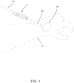
- FIG. 1 illustrates an exemplary application of a patient safety disconnect, or a breakaway medical tubing connector apparatus (apparatus) 10, positioned on a medical tube line.
- Apparatus 10 may be used in any appropriate medical gas, fluid, or solid delivery, extraction, or monitoring line, such as an intravenous (IV) line.
- Apparatus 10 in some embodiments includes a pump side member 12 and a patient side member 14.
- Apparatus 10 is configured to decouple such that the pump side member 12 and the patient side member 14 separate if a threshold amount of tensile force is applied in opposing axial directions along the apparatus 10.
- a delivery site 100 such as a catheter or other intravenous needle device is located on a patient 102.
- a first line 104 extends between apparatus 10 and a source or sink for fluid, gas, or solid material moving through the line.
- the first line 104 has a free end coupled to the apparatus 10.
- a second line 106 extends between apparatus 10 and a delivery site 100.
- the second line 106 is coupled at a free end to the apparatus 10.
- one or more valves within the apparatus 10 are opened to allow fluid, gas, and/or solid to travel through the apparatus 10 between the first line 104 and the second line 106.
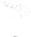
- apparatus 10 may separate such that the pump side member 12 becomes disengaged from the patient side member 14, as shown in FIG. 2 .
- One or more valves in apparatus 10 may close upon disengagement of pump side and patient side members 12, 14 such that flow of fluid, gas, or solid is prevented from exiting each of the pump side and patient side members 12, 14.
- apparatus 10 is designed such that the level of tensile force required to cause the pump side and patient side members 12, 14 to disengage is sufficiently low to provide disengagement of apparatus 10 prior to unintentional removal of delivery site 100 from patient 102.
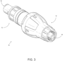
- apparatus 10 includes a pump side member 12 and a patient side member 14 positioned axially opposite the pump side member 12.
- the pump side member 12 includes a first fitting 13 in some embodiments.
- the first fitting 13 can include any suitable tube or hose fitting configured to engage a corresponding free end of a medical tube.
- first fitting 13 can include a hose barb fitting, a female luer fitting, a male luer fitting, a male threaded fitting, a female threaded fitting, or any other suitable fitting.
- the patient side member 14 includes a second fitting 15 in some embodiments.
- the second fitting 15 can be any suitable tube or hose fitting configured to engage a corresponding free end of a medical tube.
- second fitting 15 can include a hose barb fitting, a female luer fitting, a male luer fitting, a male threaded fitting, a female threaded fitting, or any other suitable fitting.
- the apparatus 10 may be inserted onto an existing medical line. One end may be specifically adapted to directly couple to a medical line. Other embodiments may provide alternative connections to the medical line such as luer locks and other similar adaptors. One end of the apparatus 10 may be preinstalled on a portion of a medical line.
- a second medical line typically a patient end of the medical line with the delivery site 100 into the patient 102
- a second medical line typically a patient end of the medical line with the delivery site 100 into the patient 102
- the apparatus 10 may be configured to couple to many existing lines as these lines often are currently configured with a luer lock on the end of the medical line.
- FIG. 4 demonstrates an exemplary embodiment of an apparatus 10 where the pump side and patient side members 12, 14 are coupled together such that a fluid, gas, or solid may pass through the apparatus 10 for delivery to a patient 102 at a delivery site 100.
- a medical provider may be administering a saline solution to a patient 102 through a medical line.
- a first line 104 may be coupled to a first fitting 13 of the pump side member 12.
- the saline solution would then enter the apparatus 10 at the flow inlet 16.
- a channel 26 disposed about an axis 24 runs through the pump side and patient side members 12, 14 when the pump side and patient side members 12, 14 are coupled together.
- the saline solution flows through the pump side member 12 to the patient side member 14 via the channel 26.
- a second line 106 may be coupled to a second fitting 15 of the patient side member 14.
- the saline solution would then flow out of the patient side member 14 and the apparatus 10 via the flow outlet 18 into the second line 106 which would then deliver the saline solution to the patient 102 via the delivery site 100.
- the apparatus 10 includes at least one valve to prevent the flow of fluids, gases, or solids when the pump side member 12 is decoupled from the patient side member 14.
- a first valve 20 is disposed within the pump side member 12.
- the first valve 20 may comprise an active valve.
- the active valve 20 is configured to allow fluids to pass through the active valve 20 when the pump side and patient side members 12, 14 are coupled.
- the active valve 20 is activated and fluids may pass through the pump side member 12 and when the pump side and patient side members 12, 14 are decoupled, the active valve 20 is not activated and fluids may not pass through the pump side member 12. This prevents a loss of fluids from occurring in the instance of a disconnect, whether accidental or purposeful.
- active valves may be implemented in this embodiment, including a QOSINA TM check valve.
- a second valve may be disposed within the patient side member 12.
- the second valve 22 may comprise a passive valve.
- the passive valve 22 may be configured to allow flow to occur in one direction.
- the passive valve 22 may also be described as a unidirectional valve.
- the fluids are unable to pass through the passive valve 22 in the opposite direction. This prevents the loss of fluids from occurring in the instance of a disconnect, whether accidental or purposeful. This also prevents a backflow of fluids from a patient 102 to the pump side member 12 and the first line 104.
- a backflow of fluids from a patient 102 may occasionally occur, including instances in which an IV delivery bag has been exhausted and a small portion of blood and other fluids travel away from the patient 102, either due to forces exerted by pressure gradients or diffusion. Fluids traveling from the patient into the first and second lines 104, 106 contaminate the lines 104, 106 such that the lines need to be replaced. With a passive valve 22 or unidirectional valve disposed in the patient side member 14, fluids are unable to move in a reverse direction and contaminate the pump side member 12 and the first line 104.
- a variety of unidirectional or passive valves may be implemented in this embodiment, including a duckbill valve.
- FIG. 5 demonstrates an exemplary embodiment in which a first valve 20 is disposed in the pump side member 12 of the apparatus 10.
- FIG. 6 demonstrates an exemplary embodiment in which a second valve 22 is disposed in the patient side member 14 of the apparatus 10.
- FIG. 7 provides a representation of an exemplary first valve 20 disposed in a first valve chamber 21 of the pump side member 12 of the apparatus 10.
- the first valve 20 is an active valve.
- the first valve 20 comprises a piston 28, a support base 29, and a diaphragm 30.
- the diaphragm 30 forms a seal with the inner wall 31 of the pump side member 12 such that fluid is unable to pass through the pump side member 12.
- the piston 28 may be manually biased toward the diaphragm 30 such that the diaphragm 30 biases away from the inner wall 31 and breaks the seal between the diaphragm 30 and the inner wall 31.
- the diaphragm 30 When the diaphragm 30 is biased away from the inner wall 31, fluid is able to flow past the diaphragm 30, past the piston 29, and through the pump side member 12.
- the diaphragm 30 may rest on a support base 29 within the first valve chamber 21.
- the support base 29 may be configured to permit fluids to pass from the flow inlet 16 into the first valve chamber 21.
- the support base 29 may also be configured to bias the diaphragm 30 toward the inner walls 31 of the pump side member 12 when the piston 28 is not exerting a force on the diaphragm 30, thus creating a seal between the diaphragm 30 and the inner walls 31.
- the seal between the diaphragm 30 and the inner walls 31 may also be a result of fluids being forced from a pump into the pump side member 12 and pressing the diaphragm 30 against the inner walls 31.
- the seal may be a result of both forces previously discussed.
- FIG. 8 an exemplary embodiment of a patient side member 14 disposed about an axis 24 is depicted.
- the patient side member 14 further comprises a stem or cannula 32, a second valve chamber 23, a flow outlet 18, and a channel 26 running through the patient side member 14.
- a second valve 22 may be disposed in the second valve chamber 23.
- the second valve 22 may be a unidirectional valve or more specifically a duckbill valve, permitting fluids to travel through the second valve 22 in a single direction.
- the cannula 32 extends from the second valve chamber 23 and the flow outlet is disposed at or near the second valve chamber 23 opposite the cannula 32.
- a fluid may enter the cannula 32 and travel through the channel 26 to the second valve chamber 23.
- the second valve 22 disposed in the second valve chamber 23 is configured to permit fluid to flow from the cannula-portion of the channel 26 to the flow-outlet portion of the channel 18.
- the fluid then passes out of the patient side member 14 of the apparatus 10.
- the fluid moving from the cannula portion of the channel 26 creates internal pressure on the duckbill valve, causing the valve to open.
- external pressure on the duckbill valve causes the valve to seal shut.
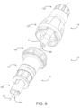
- FIGS. 9 and 10 demonstrate an embodiment in which various components are coupled together to form a pump side member 12 and a patient side member 14.
- the pump side member 12 may comprise a female luer lock adaptor 160, a luer activated check valve housing 150, and a snap fit connector 140.
- the female luer lock 160, the luer activated check valve housing 150, and the snap fit connector 140 may be integrated into a single unit.
- the patient side member 14 comprises an anti-reconnection device 120 and a key slot device 130.
- the anti-reconnection device 120 and the key slot device 130 may be integrated into a single unit.
- the cannula 32 of the patient side member 14 extends from the patient side member 14.
- a channel 26b disposed about an axis 24 may run through the cannula 32 and the patient side member 24.
- the channel 26a of the pump side member 12 is in a sealed configuration with the channel 26b of the patient side member 14.
- each element has an individual channel 26a-26e that, when each of the elements is coupled together in a sealed configuration, forms a single channel 26 through which a fluid may flow through the apparatus 10.
- the various components may remain separate or they may be manufactured in a variety of combinations of unitary components excepting the snap fit connector 140 and the anti-reconnection device 120.
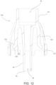
- FIG. 12 demonstrates an embodiment of an anti-reconnection device 120.
- the anti-reconnection device 120 comprises a neck 121 and a stem or cannula 32.
- a channel 26 passes through both the neck 121 and the cannula 32.
- the channel 26 and the anti-reconnection device 120 may be disposed about an axis 24.
- the neck 121 defines a second valve chamber 23 into which a second valve 22 may be placed to control the flow and the direction of flow of liquids through the apparatus 10.
- Many varying valves may be placed in the chamber, but one embodiment includes a duckbill valve to control the direction of flow of liquids in the apparatus 10.
- An anti-reconnection device 120 comprises at least one securing arm 122.
- the securing arm 122 is configured to allow the apparatus 10 to detachably couple, thus allowing a medical line to release when a force is applied to the medical line across the apparatus 10.
- the securing arm 122 extends from the anti-reconnection device 120 at a distal end of the neck 121.
- the securing arms 122 extend from the neck 121 such that the securing arms 133 are located radially outward from the cannula 32.
- the securing arms 122 may be substantially perpendicular to the axis 24.
- a securing joint 123 defines a bend at which the securing arms 122 are no longer parallel with the axis 24 and begin extending radially outward from the axis 24 at an angle greater than 90 degrees.
- a gripping surface 124 extending from the securing arms 122 at the securing joint 123 is at an angle 125 less than 90 degrees relative to a radial axis 126 extending perpendicularly from the first axis 24 running through the channel 26. See FIGS. 17e and 18d .
- the anti-reconnection device 120 may include a shield 127.
- the shield 127 may be disposed radially outward from the gripping surface 124 and in other embodiments about the securing arms 122.
- the shield 127 prevents the securing arms 122 from being intentionally or unintentionally contacted by a patient or otherwise.
- the shield 127 defines securing arm guard receiving slots 128.
- the securing arm guard receiving slots 128 are configured to receive securing arm guards 136 which will be further described hereinafter.
- FIG. 13 demonstrates an embodiment of a key slot device 130.
- the key slot device 130 substantially corresponds to an anti-reconnection device 120 to form the patient side member 14.
- the key slot device 130 may comprise a male luer lock 132 having chamber walls 134 extending from a distal end of the male luer lock 132, the chamber walls 134 defining a second valve chamber 23.
- the second valve chamber 23 of the anti-reconnection device 120 and the second valve chamber 23 of the key slot device 130 are the same chamber.
- the walls of each of the anti-reconnection device 120 and the key slot device 132 may correspond in such a way that they form a single second valve chamber 23 as is demonstrated in FIG. 14 .
- a second valve 22 may be inserted into the second valve chamber 23 to regulate the flow and the direction of flow of fluids in the apparatus 10.
- the key slot device 130 is disposed about an axis 24 which corresponds with the axis 24 about which anti-reconnection device 120 is disposed, such that when the key slot device 120 and the anti-reconnection device 120 are coupled, there is a single axis 24 about which the patient side member 14 is disposed.
- Channel 26 runs through key slot device 120.
- the key slot device 130 further comprises securing arm guards 136.
- the securing arm guards 136 are disposed radially outward from the securing arms 122 of the anti-reconnection device 120 when coupled to the key slot device 130 as demonstrated in FIG. 14 .
- the securing arm guards 136 act as a shield to prevent access to the securing arms 122.
- the securing arm guards 136 further define key holes 138.
- the securing arm 122 when establishing a connection, because the securing arm guard 136 and the shield 127 interfere with direct access to the securing arm 122, the securing arm 122 is inaccessible.
- the securing arms 122 may only be accessed via the key holes 138 that may be disposed on the securing arm guard 136 or the shield 127.
- the key holes 138 may be configured such that the only way to access the securing arms 122 is using a special tool designed for the key holes 138. This limits the ability to establish a connection between the pump side and patient side members 12, 14 and ultimately the connection between the IV and the patient 102. Thus, when accidental disconnections do occur, a medical professional may properly evaluate the situation to determine if it is necessary to provide a new connection because of contamination.
- FIG. 14 demonstrates an exemplary embodiment of the patient side member 14.
- the patient side member 14 may be manufactured as three separate subparts (duckbill valve 22, anti-reconnection device 120, and key slot device 130).
- the subparts may be assembled and coupled using common techniques such as bonding materials, connectors, etc.
- Another embodiment may be implemented as a unitary construction for the subparts. This could include 3-D printing techniques.
- the concepts disclosed herein do not depend on the patient side member 14 being either multiple subparts assembled or a unitary, singular member.
- the pump side member 12 provides an attachment point to which the securing arms 122 of the patient side member 14 may couple, thus the pump side member 12 and the patient side member 14 are coupled to form the apparatus 10.
- FIG. 15 discloses an exemplary embodiment of the pump side member 12.
- the pump side member 12 may comprise a female luer lock 160, a luer activated check valve device 150, and a snap fit connector 140.
- the pump side member 12 may comprise different subparts, such as quick connectors, male luer locks, bayonet connectors, compression fittings, barbed connectors, flare connectors, swappable valves, etc.
- the pump side member 12 may be a unitary whole and all of the components and functions disclosed by the female luer lock 160, the luer activated check valve device 150, and the snap fit connector 140 may be integrated into a single unit.
- FIG. 16 depicts an exemplary embodiment of a snap fit connector 140.
- the snap fit connector 140 may be disposed about an axis 24.
- the axis 24 may run through all of the various subparts of the pump side member 12 when coupled and aligned with the axis 24 of the patient side member 14 and when the pump side member 12 and the patient side member 12 are detachably coupled.
- a channel 26 may disposed within the snap fit connector 140. When a channel 26 and the patient side member 14 are detachably coupled, the members 12, 14 form a single channel 26.
- the snap fit connector 140 may also define a toric joint recess 142. This recess 142 is configured to receive a toric joint 144 to prevent fluid leakage when the members 12, 14 are detachably coupled.
- An exemplary embodiment of the snap fit connector 140 comprises a securing bar 146.
- the securing bar 146 is configured to receive the securing arms 122 of the anti-reconnection device 120.
- the relationship between the securing arms 122 and the securing bar 146 provide the apparatus 10 with the anti-reconnection and breakaway functionalities.
- the securing bar 146 in some exemplary embodiments may further comprise an angled receiving surface 148.
- the angled receiving surface 148 may be at an angle 149 of less than 90 degrees in relation to a radial axis 126 extending perpendicularly out from the first axis 24. See FIGS. 17e and 18d .
- the angled receiving surface 148 of the securing bar 146 and the gripping surface 124 of the securing arms 122 are configured to be complimentary to one another. In some embodiments this may result in the angled receiving surface 148 and the gripping surface 124 being flush when the pump side and patient side members 12, 14 are detachably coupled.
- the gripping surface 124 and the angled receiving surface 148 are substantially in contact.
- the surfaces 124, 128 are substantially parallel but not perfectly parallel and thus are unable to maintain a perfectly flush contact surface.
- the securing arms 122 are slightly biased radially inward by the securing bar 146. This means that the securing arms 122 bias radially outward because the materials prefer to remain in an unbiased state.
- the securing bar 146 is positioned in such a way that when the members 12, 14 are detachably coupled, the securing arms 122 and the securing bar 146 are in contact but the securing arms 122 are not biased radially inward.
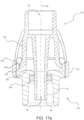
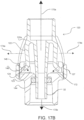
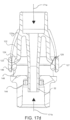
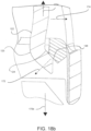
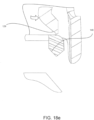
- FIGS. 17a-17f and 18a-18e demonstrate the process of detachment from and coupling of the pump side member 12 to the patient side member 14.
- the securing arm 155 In order for the pump side member 12 to detach from the patient side member 14, the securing arm 155 must pass or clear the securing bar 146.
- angled receiving surface 148 of the securing bar 146 and the gripping surface 124 of the securing arms 122 in some embodiments may provide for the detachability of the pump side member 12 from the patient side member 14.
- the outwardly opposing axial force 170 required to achieve detachment of the pump side and patient side members 12, 14 may be modified by varying several features of the apparatus 10.
- the angle 125, 149 at which the angled receiving surface 148 and the gripping surface 124 are disposed results in varying degrees of resistance to detachment. See FIG. 18d .
- the resulting force 172 is more complementary to the direction of biasing of the securing arm 122 for detachment and will result in radially inward force applied to the securing arm 122 and will not result in axial force on the securing arm 122.
- Radially inward force will cause the securing arms 122 to bias radially inward.
- Axial force will result in tension on the securing arms 122, but will not bias the securing arms 122.
- the tension will instead provide resistance to the outwardly opposing axial forces 170.
- the closer to parallel the angled receiving surface 148 and the gripping surface 124 are relative to the radial axis 126 the more the force between the two components 124, 148 will be directed axially and not radially.
- greater outwardly opposing axial force 170 is required to result in a radially inward biasing of the securing arms 122. See FIG. 17e .
- the outwardly opposing axial force 170 required to achieve detachment may be varied by the length of the gripping surface 124. If the gripping surface 124 is longer, the securing arms 122 must bias a greater distance radially inward to clear the angled receiving surface 148 and the securing bar 146. A greater amount of force is required to bias the securing arm 122 radially inward, therefore, if a greater or lesser amount of outwardly opposing axial force 170 is desired for detachment, the length of the gripping surface 124 may be increased or decreased, respectively. This may cause certain material stress to the securing arm 122, thus the securing arm 122 may also comprise a reinforced joint 122a where the securing arm 122 extends from the anti-reconnection device 120.
- the texture of the angled receiving surface 148 and the gripping surface 124 may be altered to provide more resistance.
- the gripping surface 124 is sliding relative to the angled receiving surface 148. The sliding motion creates an opposing frictional force.
- the surface area of the two surfaces 124, 128 may be adjusted to provide varying levels of resistance. This includes larger or smaller surfaces 124, 148 or imperfect contact between the two surfaces 124, 148.
- the material and thickness of the securing arm 122 may also alter the amount of outwardly opposing axial force 170 necessary to detach the apparatus 10.
- the securing arm 122 is comprised of thicker and more rigid material, a greater force is required to radially bias the securing arms 122.
- the force necessary to decouple the two members 12, 14 may be modified to maximize the effectiveness of the apparatus 10.
- the toric joint 144 may also provide extra resistance to decoupling of the two members 12, 14.
- the relationship between the securing arms 122 and the securing bar 146 in connection with the securing arm guards 136 provide the anti-reconnection feature of the present disclosure.
- the securing arms 122 further define a deflecting surface 129.
- the securing arm 122 and the securing bar 146 are aligned such that when the two members 12, 14 are translated across the axis 24 towards each other, the deflecting surface 129 of the securing arm 122 contacts the securing bar 146.
- the deflecting surface 129 obstructs further movement and the two members 12, 14 are not able to couple.
- the deflecting surface 129 is angled substantially parallel to the gripping surface 124.
- the securing bar 146 may also be angled or rounded such that when a user applies inwardly opposing axial force 171 to the two members 12, 14 and the securing bar 146 is in contact with the deflecting surface 129, the securing arm 122 will radially bias outward, thus preventing the coupling of the two members 12,14.
- the deflecting surface 129 and the securing bar 146 are aligned to prevent coupling when the securing arm 122 is unbiased, in order to achieve coupling of the two members 12, 14, a user must manually bias the securing arms 122 radially inward such that the securing arm 122 clears and slides past the securing bar 146 when the two members 12, 14 are translated along the axis 24 towards the other.
- the securing arm guards 136 prevent access to the securing arms 122. Access is only possible through the key hole 138. A special key is required to bias the securing arms 122 radially inward. This allows a medical care provider to limit the ability to couple the two members 12, 14 to those having access to a key. When unintentional de-couplings occur, a medical care provider may assess the situation and determine whether the line may be reconnected or if a new line needs to be used because of contamination or damage to the line.
- valves 20, 22 and activating structures may be resident on the opposite member 12, 14 as previously described when fluids are being extracted from a patient 102 rather than being administered to the patient 102.
- the two members 12, 14 may also comprise dead-end caps.
- the dead end caps are configured to prevent contamination of the inner channels and components of the members 12, 14.
- the dead end caps may comprise the existing components such as the shield 127, securing bar 146, and securing arm guards 136.
- the second end of the patient side members 110 is operable to act as a first dead end cap
- the proximate end of the pump side member 12 is operable to act as a second dead end cap.
- a diameter of the channel 26 and the cannula 32 provide a protection against tampering with the valves 20, 22 of the apparatus 10. Patients, upon accidental disconnect, may try to reconnect the apparatus 10 and the diameter of the channel 26 and the cannula 32 prevent contact with the valves 20, 22 which could result in damage to the valves 20, 22 and loss of fluids due to damaged valves.
- a disconnect does occur, it is important that the flow of fluids through the device stop so as to prevent loss of fluids from a patient and prevent leakage of fluids from an IV bag, for instance.
- Some embodiments may implement a series of valves to prevent loss of fluids and resulting cleanup and danger from uncontained fluids.
- a duckbill valve 22 may be implemented in the apparatus 10 to prevent the backflow of liquids in a direction opposite the desired flow.
- the duckbill valve 22 is positioned within the downstream portion of the two members 12, 14.
- Other unidirectional valves may also be implemented in various other embodiments, as well as multidirectional valves.
- the duckbill valve 22 would be in the pump side member 12 downstream from the patient 102, whereas the duckbill valve 22 would be proximate the patient 102 if fluids where being administered to the patient 102.
- a first valve 20 is needed to prevent fluids from continuing to flow from the source when the two members 12, 14 have detached. In some embodiments, this is accomplished by providing a first valve 20 that is only active when the two members 12, 14 are coupled together. This may be accomplished by providing a cannula 32 which extends into the pump side member 12 and activates a check valve or the first valve 20. The pressure provided by the valve activating surface 34 of the cannula 32 when the two members 12, 14 are coupled activates the first valve 20. When the two members 12, 14 are separated, the valve activating surface 34 is no longer applying pressure to the first valve 20, thus preventing fluids from flowing through the first valve 20. Some embodiments may utilize a commercially available check valve such as the QOSINA TM luer activated check valve.
- a toric joint 144 may be placed within the apparatus 10 to minimize fluid loss during decoupling. As the two members 12, 14 separate from one another, the valve activating surface 34 of the cannula 32 loses contact with the first valve 20. The toric joint 144 is disposed in the channel 26 such that the seal around the cannula 32 remains intact even after the first valve 20 is inactive. Thus, the system remains sealed for a period of time even after the fisrt valve 20 is no longer active and fluids cannot pass into or through the apparatus 10. See FIGS. 17e and 17f .
Landscapes
- Health & Medical Sciences (AREA)
- Heart & Thoracic Surgery (AREA)
- Engineering & Computer Science (AREA)
- Animal Behavior & Ethology (AREA)
- Public Health (AREA)
- Biomedical Technology (AREA)
- Hematology (AREA)
- Life Sciences & Earth Sciences (AREA)
- Veterinary Medicine (AREA)
- General Health & Medical Sciences (AREA)
- Anesthesiology (AREA)
- Pulmonology (AREA)
- General Engineering & Computer Science (AREA)
- Mechanical Engineering (AREA)
- Vascular Medicine (AREA)
- Infusion, Injection, And Reservoir Apparatuses (AREA)
- External Artificial Organs (AREA)
Description
- The present disclosure relates generally to connectors for intravenous medical tubing. More particularly, the present disclosure relates to automatically sealing breakaway intravenous line connectors.
- The use of medical tubing for transferring fluids to and from a patient is common practice in a medical setting. Intravenous technologies and techniques have advanced to a degree such that many devices associated with intravenous applications are discreet and often forgotten by a patient. As such, it is not uncommon for a patient to attempt a movement that is limited by the medical tubing and the devices connected at each end of the medical tubing. This often results in discomfort, pain, and even danger to a patient as the access point into a vein of the patient is damaged. This can cause deep abrasions, tearing, and even hemorrhaging. This is especially dangerous to the patient if the access point is a major vein, artery, or organ.
- When an access point is compromised by an accidental movement, it can result in an unsanitary and dangerous environment as the patient can hemorrhage and the fluids that were either collected or being introduced into the patient will pour out from the storage containers. A patient may panic and attempt to reestablish the connection which can be dangerous as there is a risk of line contamination, which can result in extreme danger to the patient, and the patient is not trained to accomplish this task. The line, insertion point, and fluids may have been contaminated in the detachment and if the patient is able to reestablish the line, the patient is potentially introducing pathogens and other contaminates directly into the body. This can result in serious and deadly infections as well as other serious complications.
-
US2009/200796 discloses a quick-release coupling that includes a male subassembly comprising a spring-biased first valve and two latches; and a female subassembly comprising a spring biased second valve and two hollow snapping members whereby snapping the latches through the snapping members will securely assemble the male and the female sub-assemblies together, thereby opening both valves to allow fluid to flow through. -
US2006/129109 discloses a disconnect device suitable for use with an IV tube or other medical tubing device which can be either manually disconnected or automatically disconnected by the application of an axial force sufficiently low to prevent patient injury; which can be sterilely reattached after disconnection; which allows fluid flow in either direction; which shuts off fluid flow from both directions when disconnected; and which can be simply and inexpensively manufactured and assembled with techniques common to the injection molding, and medical products manufacturing industry. -
US2017/067586 discloses a breakaway connector apparatus for joining a first tubing section to a second tubing section that includes a first member and a second member positioned axially opposite the first member. The second member includes a male portion extending from the second member. A housing is disposed between the first and second members, the housing including a socket shaped to receive the male portion of the second member. An axial passage provides a flow path defined inside the housing between the first and second members. A stem is disposed in the axial passage between the first and second members. A first valve is disposed on the first or second member, and the stem engages the first valve and opens the first valve to allow flow between the first and second members through the axial passage when the male portion of the second member is fully received in the socket of the housing. -
EP2736584 discloses a coupling apparatus including a first component having a first non-mechanical valve, a second component having a second non-mechanical valve, and a third component having a first end for coupling with the first valve and a second end for coupling with the second valve. The third component has an elongated bore such that when the first end is coupled to the first valve and the second end is coupled to the second valve, a passageway is defined therethrough. The coupling apparatus includes a breakaway portion disposed between the third component and the second component and the first and second valves automatically close when the second and third components are separated from one another. -
US5820614 discloses a disconnect device for placement in a medical tubing set including a first portion with a first passageway therethrough that has a first valve therein. While the first valve is biased in a normally closed position to close the first passageway, it is operative to an open position. The disconnect device has a second portion with a second passageway therethrough that has a second valve therein. The second valve is also biased in a normally closed position to close the second passageway and it also is operative to an open position. - What is needed then are improvements in devices and methods for preventing accidental removal of intravenous insertion sites and breakaway connectors for medical tubing.
- The invention is set out in the appended set of claims. This Brief Summary is provided to introduce a selection of concepts in a simplified form that are further described below in the Detailed Description. This Summary is not intended to identify key features or essential features of the claimed subject matter, nor is it intended to be used as an aid in determining the scope of the claimed subject matter.
- One aspect of the disclosure is a breakaway connector device for placement between two medical tubing apparatuses. Commonly in current medical practice, there is a device or tube inserted within the patient that, upon exit from the patient's body, presents an apparatus for the connection of an external piece of tubing. The secondary container of fluid for infusion, or a container for removal of fluid, sometimes with a pumping mechanism along the tubing in-between the container and the patient. The connection point between these respective medical tubing segments is of utmost importance, as it presents an entry point for pathogens and is usually very close to the patient and therefore near the insertion site.
- The present disclosure allows a sealed, fluid connection between the two connecting pieces of the medical tubing, but allows a disengagement of the tubing sections from one another once a specific tension threshold or threshold range is applied, before the adhesive or securement devices fail, ultimately preventing the adverse event of premature device removal. The two ends of the devices remain attached to their respective sides of the tubing serve as protective barriers to external pathogens, and also occludes the flow of fluids to serve as a barrier to fluid leakage out of the patient or ultimately from the containers. The devices are only attachable with a special tool which is able to access the mechanism for attachment within the device.
- Numerous other objects, advantages and features of the present disclosure will be readily apparent to those of skill in the art upon a review of the following drawings and description of a preferred embodiment.
-
-
FIG. 1 is a view of an embodiment of an exemplary apparatus in use. -
FIG. 2 is a view of an embodiment of an exemplary apparatus after separation while in use. -
FIG. 3 is a perspective view of an embodiment of an exemplary apparatus. -
FIG. 4 is a sectional side view of an embodiment of an exemplary apparatus. -
FIG. 5 is a frontal view of an exemplary pump side member having a first valve disposed in the pump side member. -
FIG. 6 is a frontal view of an exemplary patient side member having a second valve disposed in the patient side member -
FIG. 7 is a sectional side view of an exemplary embodiment of a first valve disposed in a pump side member. -
FIG. 8 is a sectional side view of an exemplary embodiment of a second valve disposed in a patient side member. -
FIG. 9 is perspective view of an exemplary embodiment of pump side member and a patient side member when uncoupled. -
FIG. 10 is sectional perspective view of an exemplary embodiment of pump side member and a patient side member when uncoupled. -
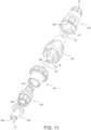
FIG. 11 is an exploded perspective view of an exemplary embodiment of an apparatus. -
FIG. 12 is a sectional side view of an exemplary embodiment of an anti-reconnection device. -
FIG. 13 is a sectional perspective view of an exemplary embodiment of a key slot device. -
FIG. 14 is a sectional perspective view of an exemplary embodiment of a key slot device coupled with an anti-reconnection device. -
FIG. 15 is a sectional side view of an exemplary embodiment of a pump side member -
FIG. 16 is a sectional perspective view of an exemplary embodiment of a snap fit connector. -
FIG. 17a-f is a sectional side view of an embodiment of a snap fit connector and an anti-reconnection device as axial force is applied to the apparatus. -
FIG. 18a-e is a close-up sectional side view of an embodiment of a snap fit connector and an anti-reconnection device as axial force is applied to the apparatus. - While the making and using of various embodiments of the present invention are discussed in detail below, it should be appreciated that the present invention provides many applicable inventive concepts that are embodied in a wide variety of specific contexts. The specific embodiments discussed herein are merely illustrative of specific ways to make and use the invention and do not delimit the scope of the invention. Those of ordinary skill in the art will recognize numerous equivalents to the specific apparatus and methods described herein. Such equivalents are considered to be within the scope of this invention and are covered by the claims.
- In the drawings, not all reference numbers are included in each drawing, for the sake of clarity. In addition, positional terms such as "upper," "lower," "side," "top," "bottom," etc. refer to the apparatus when in the orientation shown in the drawing, or as otherwise described. A person of skill in the art will recognize that the apparatus can assume different orientations when in use.
- Referring further to the drawings,
FIG. 1 illustrates an exemplary application of a patient safety disconnect, or a breakaway medical tubing connector apparatus (apparatus) 10, positioned on a medical tube line.Apparatus 10 may be used in any appropriate medical gas, fluid, or solid delivery, extraction, or monitoring line, such as an intravenous (IV) line.Apparatus 10 in some embodiments includes apump side member 12 and apatient side member 14.Apparatus 10 is configured to decouple such that thepump side member 12 and thepatient side member 14 separate if a threshold amount of tensile force is applied in opposing axial directions along theapparatus 10. As seen inFIG. 1 , adelivery site 100 such as a catheter or other intravenous needle device is located on apatient 102. Afirst line 104 extends betweenapparatus 10 and a source or sink for fluid, gas, or solid material moving through the line. Thefirst line 104 has a free end coupled to theapparatus 10. Asecond line 106 extends betweenapparatus 10 and adelivery site 100. Thesecond line 106 is coupled at a free end to theapparatus 10. When thepump side member 12 and thepatient side member 14 are coupled, one or more valves within theapparatus 10 are opened to allow fluid, gas, and/or solid to travel through theapparatus 10 between thefirst line 104 and thesecond line 106. In the event thepatient 102 moves in a manner to impart a threshold tensile force on the first andsecond lines apparatus 10 may separate such that thepump side member 12 becomes disengaged from thepatient side member 14, as shown inFIG. 2 . One or more valves inapparatus 10 may close upon disengagement of pump side andpatient side members patient side members - In some embodiments,
apparatus 10 is designed such that the level of tensile force required to cause the pump side andpatient side members apparatus 10 prior to unintentional removal ofdelivery site 100 frompatient 102. - Referring to
FIG. 3 , in someembodiments apparatus 10 includes apump side member 12 and apatient side member 14 positioned axially opposite thepump side member 12. Thepump side member 12 includes a first fitting 13 in some embodiments. The first fitting 13 can include any suitable tube or hose fitting configured to engage a corresponding free end of a medical tube. For example, in some embodiments, first fitting 13 can include a hose barb fitting, a female luer fitting, a male luer fitting, a male threaded fitting, a female threaded fitting, or any other suitable fitting. Similarly, thepatient side member 14 includes a second fitting 15 in some embodiments. The second fitting 15 can be any suitable tube or hose fitting configured to engage a corresponding free end of a medical tube. For example, in some embodiments, second fitting 15 can include a hose barb fitting, a female luer fitting, a male luer fitting, a male threaded fitting, a female threaded fitting, or any other suitable fitting. - Although many forms, embodiments, and implementations are possible, this particular embodiment as shown in
FIG. 3 will be discussed in detail while other embodiments will be described in this application, including combining subparts into a single part and variations to a specific implementation of the apparatus. Theapparatus 10 may be inserted onto an existing medical line. One end may be specifically adapted to directly couple to a medical line. Other embodiments may provide alternative connections to the medical line such as luer locks and other similar adaptors. One end of theapparatus 10 may be preinstalled on a portion of a medical line. This allows for a second medical line, typically a patient end of the medical line with thedelivery site 100 into thepatient 102, to be directly coupled to thepatient side member 14 of theapparatus 10 via an adaptor, luer lock, or quick disconnect coupling. However, theapparatus 10 may be configured to couple to many existing lines as these lines often are currently configured with a luer lock on the end of the medical line. -
FIG. 4 demonstrates an exemplary embodiment of anapparatus 10 where the pump side andpatient side members apparatus 10 for delivery to apatient 102 at adelivery site 100. For example, a medical provider may be administering a saline solution to apatient 102 through a medical line. Afirst line 104 may be coupled to a first fitting 13 of thepump side member 12. The saline solution would then enter theapparatus 10 at theflow inlet 16. In one embodiment, achannel 26 disposed about anaxis 24 runs through the pump side andpatient side members patient side members pump side member 12 to thepatient side member 14 via thechannel 26. Asecond line 106 may be coupled to a second fitting 15 of thepatient side member 14. The saline solution would then flow out of thepatient side member 14 and theapparatus 10 via theflow outlet 18 into thesecond line 106 which would then deliver the saline solution to thepatient 102 via thedelivery site 100. - In some embodiments, the
apparatus 10 includes at least one valve to prevent the flow of fluids, gases, or solids when thepump side member 12 is decoupled from thepatient side member 14. In one embodiment, afirst valve 20 is disposed within thepump side member 12. Thefirst valve 20 may comprise an active valve. Theactive valve 20 is configured to allow fluids to pass through theactive valve 20 when the pump side andpatient side members patient side members active valve 20 is activated and fluids may pass through thepump side member 12 and when the pump side andpatient side members active valve 20 is not activated and fluids may not pass through thepump side member 12. This prevents a loss of fluids from occurring in the instance of a disconnect, whether accidental or purposeful. One of skill in the art would readily appreciate that a variety of active valves may be implemented in this embodiment, including a QOSINA™ check valve. - A second valve may be disposed within the
patient side member 12. Thesecond valve 22 may comprise a passive valve. Thepassive valve 22 may be configured to allow flow to occur in one direction. Thepassive valve 22 may also be described as a unidirectional valve. When fluids are being pushed through theapparatus 10 from thepump side member 12 to thepatient side member 14, fluids are able to freely flow through thepassive valve 22. However, if fluids are somehow being forced through theapparatus 10 in an opposite direction from what was previously described, the fluids are unable to pass through thepassive valve 22 in the opposite direction. This prevents the loss of fluids from occurring in the instance of a disconnect, whether accidental or purposeful. This also prevents a backflow of fluids from apatient 102 to thepump side member 12 and thefirst line 104. A backflow of fluids from apatient 102 may occasionally occur, including instances in which an IV delivery bag has been exhausted and a small portion of blood and other fluids travel away from thepatient 102, either due to forces exerted by pressure gradients or diffusion. Fluids traveling from the patient into the first andsecond lines lines passive valve 22 or unidirectional valve disposed in thepatient side member 14, fluids are unable to move in a reverse direction and contaminate thepump side member 12 and thefirst line 104. One of skill in the art would readily appreciate that a variety of unidirectional or passive valves may be implemented in this embodiment, including a duckbill valve. -
FIG. 5 demonstrates an exemplary embodiment in which afirst valve 20 is disposed in thepump side member 12 of theapparatus 10.FIG. 6 demonstrates an exemplary embodiment in which asecond valve 22 is disposed in thepatient side member 14 of theapparatus 10. -
FIG. 7 provides a representation of an exemplaryfirst valve 20 disposed in afirst valve chamber 21 of thepump side member 12 of theapparatus 10. In this embodiment, thefirst valve 20 is an active valve. Thefirst valve 20 comprises apiston 28, asupport base 29, and adiaphragm 30. When thefirst valve 20 is not activated, thediaphragm 30 forms a seal with the inner wall 31 of thepump side member 12 such that fluid is unable to pass through thepump side member 12. Thepiston 28 may be manually biased toward thediaphragm 30 such that thediaphragm 30 biases away from the inner wall 31 and breaks the seal between thediaphragm 30 and the inner wall 31. When thediaphragm 30 is biased away from the inner wall 31, fluid is able to flow past thediaphragm 30, past thepiston 29, and through thepump side member 12. Thediaphragm 30 may rest on asupport base 29 within thefirst valve chamber 21. Thesupport base 29 may be configured to permit fluids to pass from theflow inlet 16 into thefirst valve chamber 21. Thesupport base 29 may also be configured to bias thediaphragm 30 toward the inner walls 31 of thepump side member 12 when thepiston 28 is not exerting a force on thediaphragm 30, thus creating a seal between thediaphragm 30 and the inner walls 31. The seal between thediaphragm 30 and the inner walls 31 may also be a result of fluids being forced from a pump into thepump side member 12 and pressing thediaphragm 30 against the inner walls 31. The seal may be a result of both forces previously discussed. - Now referring to
FIG. 8 , an exemplary embodiment of apatient side member 14 disposed about anaxis 24 is depicted. Thepatient side member 14 further comprises a stem orcannula 32, asecond valve chamber 23, aflow outlet 18, and achannel 26 running through thepatient side member 14. Asecond valve 22 may be disposed in thesecond valve chamber 23. Thesecond valve 22 may be a unidirectional valve or more specifically a duckbill valve, permitting fluids to travel through thesecond valve 22 in a single direction. In one embodiment, thecannula 32 extends from thesecond valve chamber 23 and the flow outlet is disposed at or near thesecond valve chamber 23 opposite thecannula 32. In this embodiment, a fluid may enter thecannula 32 and travel through thechannel 26 to thesecond valve chamber 23. Thesecond valve 22 disposed in thesecond valve chamber 23 is configured to permit fluid to flow from the cannula-portion of thechannel 26 to the flow-outlet portion of thechannel 18. The fluid then passes out of thepatient side member 14 of theapparatus 10. The fluid moving from the cannula portion of thechannel 26 creates internal pressure on the duckbill valve, causing the valve to open. When fluids are travelling in an opposite direction, from the flow outlet-portion of thechannel 18, external pressure on the duckbill valve causes the valve to seal shut. -
FIGS. 9 and10 demonstrate an embodiment in which various components are coupled together to form apump side member 12 and apatient side member 14. In some embodiments, thepump side member 12 may comprise a femaleluer lock adaptor 160, a luer activatedcheck valve housing 150, and a snapfit connector 140. In some embodiments, thefemale luer lock 160, the luer activatedcheck valve housing 150, and the snapfit connector 140 may be integrated into a single unit. Thepatient side member 14 comprises ananti-reconnection device 120 and akey slot device 130. In some embodiments, theanti-reconnection device 120 and thekey slot device 130 may be integrated into a single unit. Each of these elements and various embodiments will be discussed in more detail below. - In one embodiment, the
cannula 32 of thepatient side member 14 extends from thepatient side member 14. Achannel 26b disposed about anaxis 24 may run through thecannula 32 and thepatient side member 24. When thecannula 32 is inserted into thepump side member 12, thechannel 26a of thepump side member 12 is in a sealed configuration with thechannel 26b of thepatient side member 14. When thepump side member 12 and thepatient side member 14 are comprised of the various elements previously recited as shown inFIG. 11 , each element has anindividual channel 26a-26e that, when each of the elements is coupled together in a sealed configuration, forms asingle channel 26 through which a fluid may flow through theapparatus 10. The various components may remain separate or they may be manufactured in a variety of combinations of unitary components excepting the snapfit connector 140 and theanti-reconnection device 120. -
FIG. 12 demonstrates an embodiment of ananti-reconnection device 120. Theanti-reconnection device 120 comprises aneck 121 and a stem orcannula 32. Achannel 26 passes through both theneck 121 and thecannula 32. Thechannel 26 and theanti-reconnection device 120 may be disposed about anaxis 24. In one embodiment, theneck 121 defines asecond valve chamber 23 into which asecond valve 22 may be placed to control the flow and the direction of flow of liquids through theapparatus 10. Many varying valves may be placed in the chamber, but one embodiment includes a duckbill valve to control the direction of flow of liquids in theapparatus 10. - An
anti-reconnection device 120 comprises at least one securingarm 122. The securingarm 122 is configured to allow theapparatus 10 to detachably couple, thus allowing a medical line to release when a force is applied to the medical line across theapparatus 10. In some embodiments the securingarm 122 extends from theanti-reconnection device 120 at a distal end of theneck 121. The securingarms 122 extend from theneck 121 such that the securing arms 133 are located radially outward from thecannula 32. In some embodiments, the securingarms 122 may be substantially perpendicular to theaxis 24. At a distal end of the securingarms 122, a securing joint 123 defines a bend at which the securingarms 122 are no longer parallel with theaxis 24 and begin extending radially outward from theaxis 24 at an angle greater than 90 degrees. Thus, agripping surface 124 extending from the securingarms 122 at the securing joint 123 is at anangle 125 less than 90 degrees relative to a radial axis 126 extending perpendicularly from thefirst axis 24 running through thechannel 26. SeeFIGS. 17e and18d . - Another embodiment of the
anti-reconnection device 120 may include ashield 127. Theshield 127 may be disposed radially outward from thegripping surface 124 and in other embodiments about the securingarms 122. Theshield 127 prevents the securingarms 122 from being intentionally or unintentionally contacted by a patient or otherwise. In some embodiments, theshield 127 defines securing arm guard receiving slots 128. The securing arm guard receiving slots 128 are configured to receive securingarm guards 136 which will be further described hereinafter. -
FIG. 13 demonstrates an embodiment of akey slot device 130. Thekey slot device 130 substantially corresponds to ananti-reconnection device 120 to form thepatient side member 14. In one embodiment, thekey slot device 130 may comprise amale luer lock 132 havingchamber walls 134 extending from a distal end of themale luer lock 132, thechamber walls 134 defining asecond valve chamber 23. In some embodiments, thesecond valve chamber 23 of theanti-reconnection device 120 and thesecond valve chamber 23 of thekey slot device 130 are the same chamber. The walls of each of theanti-reconnection device 120 and thekey slot device 132 may correspond in such a way that they form a singlesecond valve chamber 23 as is demonstrated inFIG. 14 . Asecond valve 22 may be inserted into thesecond valve chamber 23 to regulate the flow and the direction of flow of fluids in theapparatus 10. - The
key slot device 130 is disposed about anaxis 24 which corresponds with theaxis 24 about whichanti-reconnection device 120 is disposed, such that when thekey slot device 120 and theanti-reconnection device 120 are coupled, there is asingle axis 24 about which thepatient side member 14 is disposed.Channel 26 runs throughkey slot device 120. - The
key slot device 130 further comprises securing arm guards 136. The securingarm guards 136 are disposed radially outward from the securingarms 122 of theanti-reconnection device 120 when coupled to thekey slot device 130 as demonstrated inFIG. 14 . The securingarm guards 136 act as a shield to prevent access to the securingarms 122. The securingarm guards 136 further definekey holes 138. When a medical line becomes disconnected, sometimes a patient or another individual may try to reestablish a connection of theapparatus 10. However, this can be dangerous for the patient as the lines may have become contaminated during the disconnection. Thus, when establishing a connection, because the securingarm guard 136 and theshield 127 interfere with direct access to the securingarm 122, the securingarm 122 is inaccessible. The securingarms 122 may only be accessed via thekey holes 138 that may be disposed on the securingarm guard 136 or theshield 127. Thekey holes 138 may be configured such that the only way to access the securingarms 122 is using a special tool designed for the key holes 138. This limits the ability to establish a connection between the pump side andpatient side members patient 102. Thus, when accidental disconnections do occur, a medical professional may properly evaluate the situation to determine if it is necessary to provide a new connection because of contamination. -
FIG. 14 demonstrates an exemplary embodiment of thepatient side member 14. Thepatient side member 14 may be manufactured as three separate subparts (duckbill valve 22,anti-reconnection device 120, and key slot device 130). The subparts may be assembled and coupled using common techniques such as bonding materials, connectors, etc. Another embodiment may be implemented as a unitary construction for the subparts. This could include 3-D printing techniques. However, it is to be understood that the concepts disclosed herein do not depend on thepatient side member 14 being either multiple subparts assembled or a unitary, singular member. - In order to further understand the
apparatus 10, thepump side member 12 will presently be described in more detail. Thepump side member 12 provides an attachment point to which the securingarms 122 of thepatient side member 14 may couple, thus thepump side member 12 and thepatient side member 14 are coupled to form theapparatus 10. -
FIG. 15 discloses an exemplary embodiment of thepump side member 12. In some embodiments, thepump side member 12 may comprise afemale luer lock 160, a luer activatedcheck valve device 150, and a snapfit connector 140. Depending on the lines that are being used, thepump side member 12 may comprise different subparts, such as quick connectors, male luer locks, bayonet connectors, compression fittings, barbed connectors, flare connectors, swappable valves, etc. In other embodiment, thepump side member 12 may be a unitary whole and all of the components and functions disclosed by thefemale luer lock 160, the luer activatedcheck valve device 150, and the snapfit connector 140 may be integrated into a single unit. -
FIG. 16 depicts an exemplary embodiment of a snapfit connector 140. The snapfit connector 140 may be disposed about anaxis 24. Theaxis 24 may run through all of the various subparts of thepump side member 12 when coupled and aligned with theaxis 24 of thepatient side member 14 and when thepump side member 12 and thepatient side member 12 are detachably coupled. Furthermore, achannel 26 may disposed within the snapfit connector 140. When achannel 26 and thepatient side member 14 are detachably coupled, themembers single channel 26. - The snap
fit connector 140 may also define a toricjoint recess 142. Thisrecess 142 is configured to receive a toric joint 144 to prevent fluid leakage when themembers - An exemplary embodiment of the snap
fit connector 140 comprises a securingbar 146. The securingbar 146 is configured to receive the securingarms 122 of theanti-reconnection device 120. In one embodiment, the relationship between the securingarms 122 and the securingbar 146 provide theapparatus 10 with the anti-reconnection and breakaway functionalities. - The securing
bar 146 in some exemplary embodiments may further comprise an angled receivingsurface 148. The angled receivingsurface 148 may be at anangle 149 of less than 90 degrees in relation to a radial axis 126 extending perpendicularly out from thefirst axis 24. SeeFIGS. 17e and18d . The angled receivingsurface 148 of the securingbar 146 and thegripping surface 124 of the securingarms 122 are configured to be complimentary to one another. In some embodiments this may result in the angled receivingsurface 148 and thegripping surface 124 being flush when the pump side andpatient side members patient side members gripping surface 124 and the angled receivingsurface 148 are substantially in contact. In other embodiments, thesurfaces 124, 128 are substantially parallel but not perfectly parallel and thus are unable to maintain a perfectly flush contact surface. In some embodiments, when the pump side andpatient side members arms 122 are slightly biased radially inward by the securingbar 146. This means that the securingarms 122 bias radially outward because the materials prefer to remain in an unbiased state. In other embodiments, the securingbar 146 is positioned in such a way that when themembers arms 122 and the securingbar 146 are in contact but the securingarms 122 are not biased radially inward. -
FIGS. 17a-17f and18a-18e demonstrate the process of detachment from and coupling of thepump side member 12 to thepatient side member 14. In order for thepump side member 12 to detach from thepatient side member 14, the securing arm 155 must pass or clear the securingbar 146. - As previously mentioned, occasionally a patient or other circumstances may accidentally apply a force to IV tubing. This can result in the dislodgment of the
delivery site 100 of thepatient 102, potentially causing extensive damage to the tissues of thepatient 102 as well as severe pain. The complementary nature of angled receivingsurface 148 of the securingbar 146 and thegripping surface 124 of the securingarms 122 in some embodiments may provide for the detachability of thepump side member 12 from thepatient side member 14. When an outwardly opposing axial force 170 is applied across the apparatus 10 (such as pulling IV tubing), because the angled receivingsurface 148 and thegripping surface 124 are not parallel nor perpendicular to a radial axis 126, the angled receivingsurface 148 exerts aforce 172 perpendicular to the plane of the angled receivingsurface 148 onto thegripping surface 124 in response to the outwardly opposing axial force 170 applied across theapparatus 10. Thisforce 172 is transmitted to the securingarm 122. The securingarm 122 will subsequently bias radially inward from theforce 172 exerted by the angled receivingsurface 148 as a result of the outwardly opposing axial force 170 applied across theapparatus 10. SeeFIGS. 17b and18b . When the securingarms 122 is biased radially inward, the materials of the securingarm 122 have some elasticity and exert a radially outward orientedforce 174 in order to return the securingarm 122 to its resting position. After themembers arms 122 will snap back into an unbiased position as illustrated inFIG. 18e . - The outwardly opposing axial force 170 required to achieve detachment of the pump side and
patient side members apparatus 10. First, theangle surface 148 and thegripping surface 124 are disposed results in varying degrees of resistance to detachment. SeeFIG. 18d . For example, if the angled receivingsurface 148 and thegripping surface 124 are set at an angle approaching 90 degrees relative to a radial axis 126, the resultingforce 172 is more complementary to the direction of biasing of the securingarm 122 for detachment and will result in radially inward force applied to the securingarm 122 and will not result in axial force on the securingarm 122. Radially inward force will cause the securingarms 122 to bias radially inward. Axial force will result in tension on the securingarms 122, but will not bias the securingarms 122. The tension will instead provide resistance to the outwardly opposing axial forces 170. Thus, the closer to parallel theangled receiving surface 148 and thegripping surface 124 are relative to the radial axis 126, the more the force between the twocomponents arms 122. SeeFIG. 17e . - Second, the outwardly opposing axial force 170 required to achieve detachment may be varied by the length of the
gripping surface 124. If thegripping surface 124 is longer, the securingarms 122 must bias a greater distance radially inward to clear the angled receivingsurface 148 and the securingbar 146. A greater amount of force is required to bias the securingarm 122 radially inward, therefore, if a greater or lesser amount of outwardly opposing axial force 170 is desired for detachment, the length of thegripping surface 124 may be increased or decreased, respectively. This may cause certain material stress to the securingarm 122, thus the securingarm 122 may also comprise a reinforced joint 122a where the securingarm 122 extends from theanti-reconnection device 120. - Third, the texture of the angled receiving
surface 148 and thegripping surface 124 may be altered to provide more resistance. As the outwardly opposing axial force 170 is applied to theapparatus 10, thegripping surface 124 is sliding relative to the angled receivingsurface 148. The sliding motion creates an opposing frictional force. The greater the coefficient of friction is on the twosurfaces apparatus 10. The surface area of the twosurfaces 124, 128 may be adjusted to provide varying levels of resistance. This includes larger orsmaller surfaces surfaces - Fourth, the material and thickness of the securing
arm 122 may also alter the amount of outwardly opposing axial force 170 necessary to detach theapparatus 10. When the securingarm 122 is comprised of thicker and more rigid material, a greater force is required to radially bias the securingarms 122. Thus, the force necessary to decouple the twomembers apparatus 10. For certain patients or insertion points, it may be necessary to have a low threshold tension or outwardly opposing axial force 170 to induce detachment as the tissue or the patient may be especially susceptible to damage or special senstivities. Other situations may call for a higher threshold for decoupling. The toric joint 144 may also provide extra resistance to decoupling of the twomembers - The relationship between the securing
arms 122 and the securingbar 146 in connection with the securingarm guards 136 provide the anti-reconnection feature of the present disclosure. The securingarms 122 further define a deflectingsurface 129. When the pump side andpatient side members arm 122 and the securingbar 146 are aligned such that when the twomembers axis 24 towards each other, the deflectingsurface 129 of the securingarm 122 contacts the securingbar 146. The deflectingsurface 129 obstructs further movement and the twomembers surface 129 is angled substantially parallel to thegripping surface 124. The securingbar 146 may also be angled or rounded such that when a user applies inwardly opposing axial force 171 to the twomembers bar 146 is in contact with the deflectingsurface 129, the securingarm 122 will radially bias outward, thus preventing the coupling of the twomembers - Because the deflecting
surface 129 and the securingbar 146 are aligned to prevent coupling when the securingarm 122 is unbiased, in order to achieve coupling of the twomembers arms 122 radially inward such that the securingarm 122 clears and slides past the securingbar 146 when the twomembers axis 24 towards the other. In some embodiments, the securingarm guards 136 prevent access to the securingarms 122. Access is only possible through thekey hole 138. A special key is required to bias the securingarms 122 radially inward. This allows a medical care provider to limit the ability to couple the twomembers - One of skill in the art would readily recognize that the components previously described may be disposed on either of the
members members arms 122, securingarm guards 146, and any other part as recited in this disclosure located on thepatient side member 14 to be relocated onto thepump side member 12 and for the securingbar 146 and other attendant elements located on thepump side member 12 to be relocated onto thepatient side member 14. Furthermore, thevalves cannula 32 and activating surface 32) may be resident on theopposite member patient 102 rather than being administered to thepatient 102. - In some embodiments, the two
members members shield 127, securingbar 146, and securing arm guards 136. In other embodiments, the second end of the patient side members 110 is operable to act as a first dead end cap, and the proximate end of thepump side member 12 is operable to act as a second dead end cap. In other embodiments, a diameter of thechannel 26 and thecannula 32 provide a protection against tampering with thevalves apparatus 10. Patients, upon accidental disconnect, may try to reconnect theapparatus 10 and the diameter of thechannel 26 and thecannula 32 prevent contact with thevalves valves - Because the
apparatus 10 is being used in fluid transfer application, if a disconnect does occur, it is important that the flow of fluids through the device stop so as to prevent loss of fluids from a patient and prevent leakage of fluids from an IV bag, for instance. Some embodiments may implement a series of valves to prevent loss of fluids and resulting cleanup and danger from uncontained fluids. As previously discussed, aduckbill valve 22 may be implemented in theapparatus 10 to prevent the backflow of liquids in a direction opposite the desired flow. Theduckbill valve 22 is positioned within the downstream portion of the twomembers duckbill valve 22 would be in thepump side member 12 downstream from thepatient 102, whereas theduckbill valve 22 would be proximate thepatient 102 if fluids where being administered to thepatient 102. - As previously discussed, a
first valve 20 is needed to prevent fluids from continuing to flow from the source when the twomembers first valve 20 that is only active when the twomembers cannula 32 which extends into thepump side member 12 and activates a check valve or thefirst valve 20. The pressure provided by thevalve activating surface 34 of thecannula 32 when the twomembers first valve 20. When the twomembers valve activating surface 34 is no longer applying pressure to thefirst valve 20, thus preventing fluids from flowing through thefirst valve 20. Some embodiments may utilize a commercially available check valve such as the QOSINA™ luer activated check valve. - In some embodiments, a toric joint 144 may be placed within the
apparatus 10 to minimize fluid loss during decoupling. As the twomembers valve activating surface 34 of thecannula 32 loses contact with thefirst valve 20. The toric joint 144 is disposed in thechannel 26 such that the seal around thecannula 32 remains intact even after thefirst valve 20 is inactive. Thus, the system remains sealed for a period of time even after thefisrt valve 20 is no longer active and fluids cannot pass into or through theapparatus 10. SeeFIGS. 17e and17f . - Thus, although there have been described particular embodiments of the present invention of a new and useful BREAKAWAY MEDICAL TUBING CONNECTOR, it is not intended that such references be construed as limitations upon the scope of this invention.
Claims (11)
- An apparatus (10) comprising:a pump side member (12) comprising:a pump side member housing have a first end and a second end; anda first channel disposed within the pump side member housing;an inlet (16) disposed at the first end of the pump side member housing and in fluid communication with the first channel;a first valve (20) disposed within the first channel downstream from the inlet (16); anda securing bar (146) coupled to the second end of the pump sidemember housing;a patient side member (14) comprising:a patient side member housing having a proximate end and a distal end;a second channel disposed within the patient side member housing;an outlet (18) disposed at the distal end of the patient side member housing and in fluid communication with the second channel;a second valve (22) disposed within the second channel upstream from the outlet (18); anda securing arm (122) coupled to a proximate end of the pump sidemember housing;wherein the pump side member (12) is configured to detachably couple to the patient side member (14) via the securing bar (146) and the securing arm (122); andwherein the securing bar (146) is configured to bias the securing arm (122) radially inward when the pump side member (12) is decoupling from the patient side member (14), characterised in that:
the apparatus further comprises a securing arm guard (136) extending from the patient side member (14) and positioned radially outward from the securing arm (122), wherein the securing arm guard (136) defines a key hole (138) configured to permit access to the securing arm (122), wherein the securing arm (122) is positioned on the pump side member (12) such that when the patient side member (14) and the pump side member (12) are decoupled and inwardly opposing axial forces are applied to the patient side member (14) and the pump side member (12), a distal end of the securing arm (122) interferes with a distal portion of the securing bar (146) preventing the patient side member (14) and the pump side member (12) from detachably coupling. - The apparatus of claim 1, wherein the securing bar (146) further defines a first surface of the securing bar (146) substantially parallel to a first axis and a second surface of the securing bar (146) at a first angle less than 90 degrees relative to a radial axis, wherein the radial axis is perpendicular to the first axis, defining a securing angle relative to the first surface of the securing bar (146) and the second surface of the securing bar (146).
- The apparatus of claim 2, wherein the securing arm (122) further defines a first surface of the securing arm (122) and a second surface of the securing arm (122), wherein:the first surface of the securing arm (122) is positioned relative to the second surface of the securing arm (122) at a second angle substantially complementary to the securing angle; andthe second surface of the securing arm (122) is substantially contacting the second surface of the securing bar (146) when the patient side member (14) and the pump side member (12) are detachably coupled.
- The apparatus of claim 3, wherein the first angle and the securing angle of the second surface of the securing bar (146) are configured to bias the securing arm (122) radially inward when the patient side member (14) and the pump side member (12) are detachably coupled and outwardly opposing axial forces are applied to the patient side member (14) and the pump side member (12).
- The apparatus of claim 1, wherein the securing arm (122) is configured to slide past the securing bar (146) when the securing arm (122) is manually biased radially inward.
- The apparatus of claim 1, wherein the first valve (20) is an active valve (20).
- The apparatus of claim 6, wherein the first valve (20) is configured to be activated by a cannula that exerts an axial force on the first valve (20).
- The apparatus of claim 1, wherein the second valve (22) is a passive valve (22).
- The apparatus of claim 8, wherein the second valve is a duckbill valve (22).
- A method of coupling a detachable line connector (10), characterised by:inserting a key through a key hole (138) defined on a securing arm guard (136), wherein the securing arm guard (136) extends from a patient side member housing, wherein the patient side member housing defines a second channel and having a cannula extending from the patient side member housing;contacting a securing arm (122) with the key, wherein the securing arm (122) is disposed on the patient side member (14) and positioned radially inward from the securing arm guard (136);biasing, with the key, the securing arm (122) radially inward;inserting the cannula of the patient side member housing into a first channel of a pump side member (12), wherein a securing bar (146) is disposed on the pump side member (12) and wherein the securing arm (122) clears and passes the securing bar (146) during inserting the cannula; andreleasing the securing arm (122) such that the securing arm (122) biases radially outward and engages the securing bar (146).
- The method of claim 10, further comprising activating a first valve (20) disposed in the first channel by biasing the first valve (20) axially outward with a distal end of the cannula.
Priority Applications (1)
| Application Number | Priority Date | Filing Date | Title |
|---|---|---|---|
| EP24188827.0A EP4425027A3 (en) | 2018-01-19 | 2019-01-17 | Breakaway medical tubing connector |
Applications Claiming Priority (2)
| Application Number | Priority Date | Filing Date | Title |
|---|---|---|---|
| US201815875494A | 2018-01-19 | 2018-01-19 | |
| PCT/US2019/014062 WO2019143848A1 (en) | 2018-01-17 | 2019-01-17 | Breakaway medical tubing connector |
Related Child Applications (1)
| Application Number | Title | Priority Date | Filing Date |
|---|---|---|---|
| EP24188827.0A Division EP4425027A3 (en) | 2018-01-19 | 2019-01-17 | Breakaway medical tubing connector |
Publications (3)
| Publication Number | Publication Date |
|---|---|
| EP3740273A1 EP3740273A1 (en) | 2020-11-25 |
| EP3740273A4 EP3740273A4 (en) | 2021-10-20 |
| EP3740273B1 true EP3740273B1 (en) | 2024-07-17 |
Family
ID=67299062
Family Applications (2)
| Application Number | Title | Priority Date | Filing Date |
|---|---|---|---|
| EP24188827.0A Pending EP4425027A3 (en) | 2018-01-19 | 2019-01-17 | Breakaway medical tubing connector |
| EP19740953.5A Active EP3740273B1 (en) | 2018-01-19 | 2019-01-17 | Breakaway medical tubing connector |
Family Applications Before (1)
| Application Number | Title | Priority Date | Filing Date |
|---|---|---|---|
| EP24188827.0A Pending EP4425027A3 (en) | 2018-01-19 | 2019-01-17 | Breakaway medical tubing connector |
Country Status (3)
| Country | Link |
|---|---|
| US (2) | US10864362B2 (en) |
| EP (2) | EP4425027A3 (en) |
| ES (1) | ES2989232T3 (en) |
Families Citing this family (22)
| Publication number | Priority date | Publication date | Assignee | Title |
|---|---|---|---|---|
| CA3148088A1 (en) * | 2019-07-24 | 2021-01-28 | Quest Medical, Inc. | Filtered vacuum relief vent valve |
| US20210372551A1 (en) * | 2020-05-30 | 2021-12-02 | Linear Health Sciences, LLC | Tubing system with reassembly prevention mechanism |
| US11708924B2 (en) | 2020-06-26 | 2023-07-25 | Carefusion 303, Inc. | Connector coupling assembly |
| CN116456886A (en) * | 2020-09-25 | 2023-07-18 | 波士顿科学国际有限公司 | Delivery system adapter for endoscope |
| US12208231B2 (en) | 2021-06-30 | 2025-01-28 | Carefusion 303, Inc. | Fluid connector system |
| KR20240043763A (en) * | 2021-08-09 | 2024-04-03 | 사이트 세이버 인크. | detachable connector |
| EP4209188A1 (en) * | 2022-01-07 | 2023-07-12 | Erbe Elektromedizin GmbH | Plasma probe |
| AU2023241911A1 (en) * | 2022-04-01 | 2024-10-10 | Icu Medical, Inc. | Medical connectors |
| US12502518B2 (en) | 2022-04-07 | 2025-12-23 | Carefusion 303, Inc. | Fluid connector system |
| US12403295B2 (en) * | 2022-08-11 | 2025-09-02 | Carefusion 303, Inc. | Fluid connector system |
| US12023462B2 (en) * | 2022-09-29 | 2024-07-02 | Carefusion 303, Inc. | Fluid connector system |
| US12208230B2 (en) | 2022-11-09 | 2025-01-28 | Carefusion 303, Inc. | Fluid connector assembly that seals flow paths when the connectors are disconnected |
| US12109387B2 (en) * | 2022-11-11 | 2024-10-08 | Carefusion 303, Inc. | Connector coupling assembly |
| US12151078B2 (en) * | 2022-11-14 | 2024-11-26 | Becton, Dickinson And Company | Force-controlled release connector with integrated safety features |
| US20240167602A1 (en) * | 2022-11-18 | 2024-05-23 | Carefusion 303, Inc. | Connector coupling assembly |
| WO2024155431A1 (en) * | 2023-01-18 | 2024-07-25 | Carefusion 303, Inc. | Connector assembly with dislodgement prevention |
| US12584578B2 (en) | 2023-03-27 | 2026-03-24 | Carefusion 303, Inc. | Torsional connector coupling assembly |
| US12186518B2 (en) * | 2023-04-25 | 2025-01-07 | Carefusion 303, Inc. | Fluid connector system |
| US12429155B2 (en) * | 2023-06-06 | 2025-09-30 | Carefusion 303, Inc. | Slit-free safe disconnect |
| US12420074B2 (en) * | 2023-07-13 | 2025-09-23 | Carefusion 303, Inc. | Fluid connector assembly |
| US20250216014A1 (en) * | 2023-12-28 | 2025-07-03 | Luminoah, Inc. | Separable bi-directional check valve assembly |
| USD1105422S1 (en) | 2024-02-09 | 2025-12-09 | Icu Medical, Inc. | Medical connector cover |
Family Cites Families (76)
| Publication number | Priority date | Publication date | Assignee | Title |
|---|---|---|---|---|
| US3797510A (en) | 1971-10-28 | 1974-03-19 | Purolator Inc | Crashworthy valve |
| US3794057A (en) | 1972-06-26 | 1974-02-26 | Textron Inc | Safety breakaway fluid coupling |
| US4340049A (en) | 1979-10-18 | 1982-07-20 | Baxter Travenol Laboratories, Inc. | Breakaway valve |
| US4386622A (en) | 1979-10-18 | 1983-06-07 | Baxter Travenol Laboratories, Inc. | Breakaway valve |
| US4722725A (en) | 1983-04-12 | 1988-02-02 | Interface Biomedical Laboratories, Inc. | Methods for preventing the introduction of air or fluid into the body of a patient |
| US5364371A (en) | 1986-03-04 | 1994-11-15 | Deka Products Limited Partnership | Intravenous fluid delivery device |
| US4872471A (en) | 1988-09-21 | 1989-10-10 | Schneider Peter J | Separable and breakaway valve interconnecting a fluid line |
| US5190067A (en) | 1990-05-29 | 1993-03-02 | Nypro, Inc. | Directional flow control |
| US5070905A (en) | 1990-05-29 | 1991-12-10 | Joseph Paradis | Directional flow control |
| US5465938A (en) | 1990-05-29 | 1995-11-14 | Werge; Robert W. | Universal fluid flow control |
| US5357998A (en) | 1990-08-23 | 1994-10-25 | Woodland Technologies, Inc. | Safety system for fluid conduit |
| US5320390A (en) | 1991-11-29 | 1994-06-14 | Tokai Rubber Industries, Ltd. | Quick connector |
| US5215538A (en) | 1992-02-05 | 1993-06-01 | Abbott Laboratories | Connector-activated in-line valve |
| US5405339A (en) | 1993-09-03 | 1995-04-11 | Medtronic, Inc. | Medical connector and method for connecting medical tubing |
| US5535785A (en) | 1994-09-08 | 1996-07-16 | Nypro, Inc. | Luer-activated check valve |
| US5492147A (en) | 1995-01-17 | 1996-02-20 | Aeroquip Corporation | Dry break coupling |
| US5954313A (en) | 1995-12-29 | 1999-09-21 | Rymed Technologies, Inc. | Medical intravenous administration line connectors having a luer activated valve |
| US5848997A (en) | 1996-03-15 | 1998-12-15 | Becton Dickinson And Company | Disconnect for medical access devices |
| US5775671A (en) | 1996-06-13 | 1998-07-07 | Nypro Inc. | Luer-activated valve |
| DE69728422T2 (en) | 1996-11-18 | 2005-03-03 | Nypro Inc., Clinton | WASHABLE LOWER VALVE |
| US6883778B1 (en) | 1996-11-18 | 2005-04-26 | Nypro Inc. | Apparatus for reducing fluid drawback through a medical valve |
| US7789864B2 (en) | 1996-11-18 | 2010-09-07 | Nypro Inc. | Luer-activated valve |
| EP1716885A3 (en) | 1997-05-09 | 2006-11-15 | Pall Corporation | Connector assemblies, fluid systems, and methods for making a connection |
| US5863425A (en) * | 1997-06-19 | 1999-01-26 | Polaris Pool Systems | Filter bag for a pool cleaner |
| US6585229B2 (en) | 1999-01-27 | 2003-07-01 | Nypro Inc. | Medical nozzle securing apparatus |
| US6546947B2 (en) | 2000-01-26 | 2003-04-15 | Smart-Hose Technologies, Inc. | Safety system for fluid conduit |
| WO2002034326A2 (en) | 2000-10-23 | 2002-05-02 | Nypro, Inc. | Anti-drawback medical valve |
| JP2005500142A (en) | 2001-08-22 | 2005-01-06 | ナイプロ・インク | Medical valve with expansion member |
| WO2003030987A1 (en) | 2001-10-09 | 2003-04-17 | Nypro, Inc. | Medical valve and method of assembling the same |
| US7837658B2 (en) | 2001-11-13 | 2010-11-23 | Nypro Inc. | Anti-drawback medical valve |
| US7753892B2 (en) | 2001-11-13 | 2010-07-13 | Nypro Inc. | Anti-drawback medical valve |
| US6869426B2 (en) | 2001-11-13 | 2005-03-22 | Nypro Inc. | Anti-drawback medical valve |
| US7357792B2 (en) | 2002-10-29 | 2008-04-15 | Nypro Inc. | Positive push medical valve with internal seal |
| US20070066965A1 (en) | 2003-07-14 | 2007-03-22 | Coambs David J | Coupling device for medical lines |
| US20050015075A1 (en) | 2003-07-14 | 2005-01-20 | B & D Research And Development Inc. | Coupling device for medical lines |
| US7914502B2 (en) | 2003-07-31 | 2011-03-29 | Nypro Inc. | Anti-drawback medical valve |
| US20060129109A1 (en) * | 2003-10-28 | 2006-06-15 | Scott Randall Shaw | Reconnectable disconnect device for fluid transfer line |
| US7153296B2 (en) | 2003-11-07 | 2006-12-26 | Mitchell Martin S | Releasable tubing connector |
| JP2007537399A (en) | 2004-05-11 | 2007-12-20 | オキュペイショナル・アンド・メディカル・イノベイションズ・リミテッド | One-way valve that uses fluid pressure for opening and closing |
| US7291134B2 (en) | 2004-10-25 | 2007-11-06 | P. Rowan Smith, Jr. | Medical connector |
| US7887519B2 (en) | 2005-01-14 | 2011-02-15 | Nypro Inc. | Valve with internal lifter |
| US20080197626A1 (en) | 2005-05-16 | 2008-08-21 | David Coambs | Coupling Device for Medical Lines |
| US7803140B2 (en) | 2005-07-06 | 2010-09-28 | Icu Medical, Inc. | Medical connector with closeable male luer |
| US7922701B2 (en) | 2006-02-17 | 2011-04-12 | Buchman Alan L | Catheter cleaning devices |
| US7879012B2 (en) | 2006-04-11 | 2011-02-01 | Nypro Inc. | Medical valve with resilient sealing member |
| US8100869B2 (en) | 2006-08-11 | 2012-01-24 | Nypro Inc. | Medical valve with expandable member |
| US7988674B2 (en) | 2006-10-30 | 2011-08-02 | Medtronic, Inc. | Externally releasable body portal anchors and systems |
| US20090200796A1 (en) * | 2008-02-11 | 2009-08-13 | Chien Fu Lai | Quick-release coupling |
| EP2254653A1 (en) | 2008-02-15 | 2010-12-01 | Nypro Inc. | Self-lubricating elastomeric components for use in medical devices |
| US7766039B2 (en) | 2008-04-15 | 2010-08-03 | Marshall Excelsior Company | Quick connect fuel hose connector |
| US8235426B2 (en) * | 2008-07-03 | 2012-08-07 | Nordson Corporation | Latch assembly for joining two conduits |
| US7959192B2 (en) | 2008-07-09 | 2011-06-14 | Pall Corporation | Disconnectable connector assembly |
| US8454579B2 (en) | 2009-03-25 | 2013-06-04 | Icu Medical, Inc. | Medical connector with automatic valves and volume regulator |
| US20100249724A1 (en) | 2009-03-30 | 2010-09-30 | Np Medical Inc. | Medical Valve with Distal Seal Actuator |
| CH700975A1 (en) | 2009-05-08 | 2010-11-15 | Medela Holding Ag | DRAINAGE TUBE DEVICE AND UNIT coupling. |
| ES2696987T3 (en) | 2009-06-22 | 2019-01-21 | Np Medical Inc | Medical valve with improved backpressure seal |
| US7955317B2 (en) | 2009-06-30 | 2011-06-07 | Tyco Healthcare Group Lp | Female adaptor for feeding line |
| USD636079S1 (en) | 2009-12-22 | 2011-04-12 | Karl Storz Gmbh & Co. Kg | Irrigation adapter for shaver blades |
| JP5875974B2 (en) | 2010-03-30 | 2016-03-02 | テルモ株式会社 | Connectors and connector assemblies |
| US8795256B1 (en) | 2010-04-12 | 2014-08-05 | Jonathan R. Smith | Breakaway valve for an IV |
| US9138572B2 (en) | 2010-06-24 | 2015-09-22 | Np Medical Inc. | Medical valve with fluid volume alteration |
| US8974437B2 (en) | 2011-07-28 | 2015-03-10 | Applied Medical Technology, Inc. | Coupling for medical fluids |
| GB2537563B (en) | 2013-02-18 | 2017-09-13 | Salisbury Nhs Found Trust | Releasable connection for a tube |
| USD730518S1 (en) | 2013-09-12 | 2015-05-26 | Nordson Corporation | Quick connect fluid connector |
| EP3079756B1 (en) | 2013-12-10 | 2019-03-13 | Applied Medical Technology, Inc. | Auto-shutoff coupling |
| USD830524S1 (en) | 2014-03-14 | 2018-10-09 | Colder Products Company | Coupling |
| USD750236S1 (en) | 2014-03-19 | 2016-02-23 | ERBE-USA, Inc. | Endoscope connector |
| USD784529S1 (en) | 2014-07-31 | 2017-04-18 | Nordson Corporation | Enteral feeding connector assembly |
| USD773659S1 (en) | 2014-08-06 | 2016-12-06 | Huntleigh Technology Limited | Tri pulse connector |
| USD791724S1 (en) | 2015-05-18 | 2017-07-11 | Fresenius Kabi Deutschland Gmbh | Enteral feeding connector with tethered closure |
| USD825746S1 (en) | 2015-06-18 | 2018-08-14 | Neomed, Inc. | Syringe-to-syringe coupler |
| EP3313490B8 (en) | 2015-06-24 | 2021-03-31 | Linear Health Science, LLC | Tubing system |
| US10655768B2 (en) * | 2015-08-13 | 2020-05-19 | Site Saver, Inc. | Breakaway connector |
| JP2017209149A (en) | 2016-05-23 | 2017-11-30 | ニプロ株式会社 | Medical connector |
| USD837978S1 (en) | 2016-06-09 | 2019-01-08 | Nordson Corporation | Snap-on adapter |
| USD836191S1 (en) | 2016-12-20 | 2018-12-18 | Synaptive Medical (Barbados) Inc. | Suction tool handle |
-
2019
- 2019-01-17 EP EP24188827.0A patent/EP4425027A3/en active Pending
- 2019-01-17 ES ES19740953T patent/ES2989232T3/en active Active
- 2019-01-17 EP EP19740953.5A patent/EP3740273B1/en active Active
- 2019-02-11 US US16/272,559 patent/US10864362B2/en active Active
-
2020
- 2020-12-15 US US17/122,481 patent/US11291822B2/en active Active
Also Published As
| Publication number | Publication date |
|---|---|
| US10864362B2 (en) | 2020-12-15 |
| US20190224468A1 (en) | 2019-07-25 |
| ES2989232T3 (en) | 2024-11-25 |
| US11291822B2 (en) | 2022-04-05 |
| EP3740273A4 (en) | 2021-10-20 |
| US20210236794A1 (en) | 2021-08-05 |
| EP3740273A1 (en) | 2020-11-25 |
| EP4425027A3 (en) | 2024-11-13 |
| EP4425027A2 (en) | 2024-09-04 |
Similar Documents
| Publication | Publication Date | Title |
|---|---|---|
| US11291822B2 (en) | Breakaway medical tubing connector | |
| US4433973A (en) | Reusable tube connector assembly | |
| EP2736584B1 (en) | Coupling for medical fluids | |
| RU2394608C2 (en) | Rod luer-lock connector, pin connector and method of detaching rod connector from receiving connector | |
| US7037302B2 (en) | Positive flow needleless connector | |
| AU714127B2 (en) | Medical intravenous administration line connectors having a luer or pressure activated valve | |
| EP2331191B1 (en) | Closed male luer device for minimizing leakage during connection and disconnection | |
| US5520665A (en) | Connecting apparatus for medical conduits | |
| EP2956204B1 (en) | Releasable connection for a tube | |
| AU707044B2 (en) | Transfer set connector with a locking lid and a method of using the same | |
| US20220296869A1 (en) | Breakaway medical tubing connector | |
| US10967169B2 (en) | Medical connector, infusion set, and fluid collection method | |
| US20250032758A1 (en) | Needle assemblies and safety catheter assemblies with blood diverting feature | |
| AU2019209934B2 (en) | Breakaway medical tubing connector | |
| CA3224140A1 (en) | Systems and methods for directing fluid flow | |
| EP4122526A1 (en) | Coupler device for valve assembly for use with medical infusion device | |
| BR112020014575B1 (en) | APPARATUS IS A METHOD FOR ATTACHING A DETACHABLE IN-LINE CONNECTOR | |
| US20260069849A1 (en) | Breakaway intra-medical tubing connector assembly | |
| CA3167196C (en) | Coupler device for valve assembly for use with medical infusion device | |
| US20240189566A1 (en) | Vent device, port assembly and vascular access assembly | |
| MXPA96001469A (en) | Connector for med tube |
Legal Events
| Date | Code | Title | Description |
|---|---|---|---|
| STAA | Information on the status of an ep patent application or granted ep patent |
Free format text: STATUS: THE INTERNATIONAL PUBLICATION HAS BEEN MADE |
|
| PUAI | Public reference made under article 153(3) epc to a published international application that has entered the european phase |
Free format text: ORIGINAL CODE: 0009012 |
|
| STAA | Information on the status of an ep patent application or granted ep patent |
Free format text: STATUS: REQUEST FOR EXAMINATION WAS MADE |
|
| 17P | Request for examination filed |
Effective date: 20200811 |
|
| AK | Designated contracting states |
Kind code of ref document: A1 Designated state(s): AL AT BE BG CH CY CZ DE DK EE ES FI FR GB GR HR HU IE IS IT LI LT LU LV MC MK MT NL NO PL PT RO RS SE SI SK SM TR |
|
| AX | Request for extension of the european patent |
Extension state: BA ME |
|
| DAV | Request for validation of the european patent (deleted) | ||
| DAX | Request for extension of the european patent (deleted) | ||
| REG | Reference to a national code |
Ref country code: DE Free format text: PREVIOUS MAIN CLASS: A61M0039100000 Ref country code: DE Ref legal event code: R079 Ref document number: 602019055358 Country of ref document: DE Free format text: PREVIOUS MAIN CLASS: A61M0039100000 Ipc: A61M0039060000 |
|
| A4 | Supplementary search report drawn up and despatched |
Effective date: 20210917 |
|
| RIC1 | Information provided on ipc code assigned before grant |
Ipc: F16L 37/32 20060101ALI20210914BHEP Ipc: F16L 37/098 20060101ALI20210914BHEP Ipc: A61M 39/26 20060101ALI20210914BHEP Ipc: A61M 39/24 20060101ALI20210914BHEP Ipc: A61M 39/22 20060101ALI20210914BHEP Ipc: A61M 39/20 20060101ALI20210914BHEP Ipc: A61M 5/158 20060101ALI20210914BHEP Ipc: A61M 39/10 20060101ALI20210914BHEP Ipc: A61M 39/06 20060101AFI20210914BHEP |
|
| GRAP | Despatch of communication of intention to grant a patent |
Free format text: ORIGINAL CODE: EPIDOSNIGR1 |
|
| STAA | Information on the status of an ep patent application or granted ep patent |
Free format text: STATUS: GRANT OF PATENT IS INTENDED |
|
| INTG | Intention to grant announced |
Effective date: 20240201 |
|
| GRAS | Grant fee paid |
Free format text: ORIGINAL CODE: EPIDOSNIGR3 |
|
| GRAA | (expected) grant |
Free format text: ORIGINAL CODE: 0009210 |
|
| STAA | Information on the status of an ep patent application or granted ep patent |
Free format text: STATUS: THE PATENT HAS BEEN GRANTED |
|
| RIN1 | Information on inventor provided before grant (corrected) |
Inventor name: MYKLEBY, JORDAN Inventor name: CLEMENT, VANCE Inventor name: JONES, SPENCER |
|
| AK | Designated contracting states |
Kind code of ref document: B1 Designated state(s): AL AT BE BG CH CY CZ DE DK EE ES FI FR GB GR HR HU IE IS IT LI LT LU LV MC MK MT NL NO PL PT RO RS SE SI SK SM TR |
|
| P01 | Opt-out of the competence of the unified patent court (upc) registered |
Free format text: CASE NUMBER: APP_37696/2024 Effective date: 20240624 |
|
| REG | Reference to a national code |
Ref country code: CH Ref legal event code: EP |
|
| REG | Reference to a national code |
Ref country code: DE Ref legal event code: R096 Ref document number: 602019055358 Country of ref document: DE |
|
| REG | Reference to a national code |
Ref country code: IE Ref legal event code: FG4D |
|
| REG | Reference to a national code |
Ref country code: LT Ref legal event code: MG9D |
|
| REG | Reference to a national code |
Ref country code: NL Ref legal event code: MP Effective date: 20240717 |
|
| REG | Reference to a national code |
Ref country code: ES Ref legal event code: FG2A Ref document number: 2989232 Country of ref document: ES Kind code of ref document: T3 Effective date: 20241125 |
|
| PG25 | Lapsed in a contracting state [announced via postgrant information from national office to epo] |
Ref country code: PT Free format text: LAPSE BECAUSE OF FAILURE TO SUBMIT A TRANSLATION OF THE DESCRIPTION OR TO PAY THE FEE WITHIN THE PRESCRIBED TIME-LIMIT Effective date: 20241118 |
|
| REG | Reference to a national code |
Ref country code: AT Ref legal event code: MK05 Ref document number: 1703571 Country of ref document: AT Kind code of ref document: T Effective date: 20240717 |
|
| PG25 | Lapsed in a contracting state [announced via postgrant information from national office to epo] |
Ref country code: NL Free format text: LAPSE BECAUSE OF FAILURE TO SUBMIT A TRANSLATION OF THE DESCRIPTION OR TO PAY THE FEE WITHIN THE PRESCRIBED TIME-LIMIT Effective date: 20240717 |
|
| PG25 | Lapsed in a contracting state [announced via postgrant information from national office to epo] |
Ref country code: PT Free format text: LAPSE BECAUSE OF FAILURE TO SUBMIT A TRANSLATION OF THE DESCRIPTION OR TO PAY THE FEE WITHIN THE PRESCRIBED TIME-LIMIT Effective date: 20241118 Ref country code: NL Free format text: LAPSE BECAUSE OF FAILURE TO SUBMIT A TRANSLATION OF THE DESCRIPTION OR TO PAY THE FEE WITHIN THE PRESCRIBED TIME-LIMIT Effective date: 20240717 |
|
| PG25 | Lapsed in a contracting state [announced via postgrant information from national office to epo] |
Ref country code: NO Free format text: LAPSE BECAUSE OF FAILURE TO SUBMIT A TRANSLATION OF THE DESCRIPTION OR TO PAY THE FEE WITHIN THE PRESCRIBED TIME-LIMIT Effective date: 20241017 |
|
| PG25 | Lapsed in a contracting state [announced via postgrant information from national office to epo] |
Ref country code: GR Free format text: LAPSE BECAUSE OF FAILURE TO SUBMIT A TRANSLATION OF THE DESCRIPTION OR TO PAY THE FEE WITHIN THE PRESCRIBED TIME-LIMIT Effective date: 20241018 Ref country code: PL Free format text: LAPSE BECAUSE OF FAILURE TO SUBMIT A TRANSLATION OF THE DESCRIPTION OR TO PAY THE FEE WITHIN THE PRESCRIBED TIME-LIMIT Effective date: 20240717 Ref country code: FI Free format text: LAPSE BECAUSE OF FAILURE TO SUBMIT A TRANSLATION OF THE DESCRIPTION OR TO PAY THE FEE WITHIN THE PRESCRIBED TIME-LIMIT Effective date: 20240717 |
|
| PG25 | Lapsed in a contracting state [announced via postgrant information from national office to epo] |
Ref country code: BG Free format text: LAPSE BECAUSE OF FAILURE TO SUBMIT A TRANSLATION OF THE DESCRIPTION OR TO PAY THE FEE WITHIN THE PRESCRIBED TIME-LIMIT Effective date: 20240717 |
|
| PG25 | Lapsed in a contracting state [announced via postgrant information from national office to epo] |
Ref country code: LV Free format text: LAPSE BECAUSE OF FAILURE TO SUBMIT A TRANSLATION OF THE DESCRIPTION OR TO PAY THE FEE WITHIN THE PRESCRIBED TIME-LIMIT Effective date: 20240717 |
|
| PG25 | Lapsed in a contracting state [announced via postgrant information from national office to epo] |
Ref country code: AT Free format text: LAPSE BECAUSE OF FAILURE TO SUBMIT A TRANSLATION OF THE DESCRIPTION OR TO PAY THE FEE WITHIN THE PRESCRIBED TIME-LIMIT Effective date: 20240717 Ref country code: IS Free format text: LAPSE BECAUSE OF FAILURE TO SUBMIT A TRANSLATION OF THE DESCRIPTION OR TO PAY THE FEE WITHIN THE PRESCRIBED TIME-LIMIT Effective date: 20241117 |
|
| PG25 | Lapsed in a contracting state [announced via postgrant information from national office to epo] |
Ref country code: HR Free format text: LAPSE BECAUSE OF FAILURE TO SUBMIT A TRANSLATION OF THE DESCRIPTION OR TO PAY THE FEE WITHIN THE PRESCRIBED TIME-LIMIT Effective date: 20240717 |
|
| PG25 | Lapsed in a contracting state [announced via postgrant information from national office to epo] |
Ref country code: RS Free format text: LAPSE BECAUSE OF FAILURE TO SUBMIT A TRANSLATION OF THE DESCRIPTION OR TO PAY THE FEE WITHIN THE PRESCRIBED TIME-LIMIT Effective date: 20241017 |
|
| PG25 | Lapsed in a contracting state [announced via postgrant information from national office to epo] |
Ref country code: RS Free format text: LAPSE BECAUSE OF FAILURE TO SUBMIT A TRANSLATION OF THE DESCRIPTION OR TO PAY THE FEE WITHIN THE PRESCRIBED TIME-LIMIT Effective date: 20241017 Ref country code: PL Free format text: LAPSE BECAUSE OF FAILURE TO SUBMIT A TRANSLATION OF THE DESCRIPTION OR TO PAY THE FEE WITHIN THE PRESCRIBED TIME-LIMIT Effective date: 20240717 Ref country code: NO Free format text: LAPSE BECAUSE OF FAILURE TO SUBMIT A TRANSLATION OF THE DESCRIPTION OR TO PAY THE FEE WITHIN THE PRESCRIBED TIME-LIMIT Effective date: 20241017 Ref country code: LV Free format text: LAPSE BECAUSE OF FAILURE TO SUBMIT A TRANSLATION OF THE DESCRIPTION OR TO PAY THE FEE WITHIN THE PRESCRIBED TIME-LIMIT Effective date: 20240717 Ref country code: IS Free format text: LAPSE BECAUSE OF FAILURE TO SUBMIT A TRANSLATION OF THE DESCRIPTION OR TO PAY THE FEE WITHIN THE PRESCRIBED TIME-LIMIT Effective date: 20241117 Ref country code: HR Free format text: LAPSE BECAUSE OF FAILURE TO SUBMIT A TRANSLATION OF THE DESCRIPTION OR TO PAY THE FEE WITHIN THE PRESCRIBED TIME-LIMIT Effective date: 20240717 Ref country code: GR Free format text: LAPSE BECAUSE OF FAILURE TO SUBMIT A TRANSLATION OF THE DESCRIPTION OR TO PAY THE FEE WITHIN THE PRESCRIBED TIME-LIMIT Effective date: 20241018 Ref country code: FI Free format text: LAPSE BECAUSE OF FAILURE TO SUBMIT A TRANSLATION OF THE DESCRIPTION OR TO PAY THE FEE WITHIN THE PRESCRIBED TIME-LIMIT Effective date: 20240717 Ref country code: BG Free format text: LAPSE BECAUSE OF FAILURE TO SUBMIT A TRANSLATION OF THE DESCRIPTION OR TO PAY THE FEE WITHIN THE PRESCRIBED TIME-LIMIT Effective date: 20240717 Ref country code: AT Free format text: LAPSE BECAUSE OF FAILURE TO SUBMIT A TRANSLATION OF THE DESCRIPTION OR TO PAY THE FEE WITHIN THE PRESCRIBED TIME-LIMIT Effective date: 20240717 |
|
| PG25 | Lapsed in a contracting state [announced via postgrant information from national office to epo] |
Ref country code: DK Free format text: LAPSE BECAUSE OF FAILURE TO SUBMIT A TRANSLATION OF THE DESCRIPTION OR TO PAY THE FEE WITHIN THE PRESCRIBED TIME-LIMIT Effective date: 20240717 Ref country code: RO Free format text: LAPSE BECAUSE OF FAILURE TO SUBMIT A TRANSLATION OF THE DESCRIPTION OR TO PAY THE FEE WITHIN THE PRESCRIBED TIME-LIMIT Effective date: 20240717 Ref country code: SM Free format text: LAPSE BECAUSE OF FAILURE TO SUBMIT A TRANSLATION OF THE DESCRIPTION OR TO PAY THE FEE WITHIN THE PRESCRIBED TIME-LIMIT Effective date: 20240717 |
|
| REG | Reference to a national code |
Ref country code: DE Ref legal event code: R097 Ref document number: 602019055358 Country of ref document: DE |
|
| PG25 | Lapsed in a contracting state [announced via postgrant information from national office to epo] |
Ref country code: EE Free format text: LAPSE BECAUSE OF FAILURE TO SUBMIT A TRANSLATION OF THE DESCRIPTION OR TO PAY THE FEE WITHIN THE PRESCRIBED TIME-LIMIT Effective date: 20240717 |
|
| PG25 | Lapsed in a contracting state [announced via postgrant information from national office to epo] |
Ref country code: CZ Free format text: LAPSE BECAUSE OF FAILURE TO SUBMIT A TRANSLATION OF THE DESCRIPTION OR TO PAY THE FEE WITHIN THE PRESCRIBED TIME-LIMIT Effective date: 20240717 |
|
| PG25 | Lapsed in a contracting state [announced via postgrant information from national office to epo] |
Ref country code: SK Free format text: LAPSE BECAUSE OF FAILURE TO SUBMIT A TRANSLATION OF THE DESCRIPTION OR TO PAY THE FEE WITHIN THE PRESCRIBED TIME-LIMIT Effective date: 20240717 |
|
| PLBE | No opposition filed within time limit |
Free format text: ORIGINAL CODE: 0009261 |
|
| STAA | Information on the status of an ep patent application or granted ep patent |
Free format text: STATUS: NO OPPOSITION FILED WITHIN TIME LIMIT |
|
| 26N | No opposition filed |
Effective date: 20250422 |
|
| REG | Reference to a national code |
Ref country code: CH Ref legal event code: PL |
|
| PG25 | Lapsed in a contracting state [announced via postgrant information from national office to epo] |
Ref country code: SE Free format text: LAPSE BECAUSE OF FAILURE TO SUBMIT A TRANSLATION OF THE DESCRIPTION OR TO PAY THE FEE WITHIN THE PRESCRIBED TIME-LIMIT Effective date: 20240717 |
|
| PG25 | Lapsed in a contracting state [announced via postgrant information from national office to epo] |
Ref country code: MC Free format text: LAPSE BECAUSE OF FAILURE TO SUBMIT A TRANSLATION OF THE DESCRIPTION OR TO PAY THE FEE WITHIN THE PRESCRIBED TIME-LIMIT Effective date: 20240717 Ref country code: LU Free format text: LAPSE BECAUSE OF NON-PAYMENT OF DUE FEES Effective date: 20250117 |
|
| PG25 | Lapsed in a contracting state [announced via postgrant information from national office to epo] |
Ref country code: BE Free format text: LAPSE BECAUSE OF NON-PAYMENT OF DUE FEES Effective date: 20250131 |
|
| PG25 | Lapsed in a contracting state [announced via postgrant information from national office to epo] |
Ref country code: CH Free format text: LAPSE BECAUSE OF NON-PAYMENT OF DUE FEES Effective date: 20250131 |
|
| REG | Reference to a national code |
Ref country code: BE Ref legal event code: MM Effective date: 20250131 |
|
| PG25 | Lapsed in a contracting state [announced via postgrant information from national office to epo] |
Ref country code: IT Free format text: LAPSE BECAUSE OF NON-PAYMENT OF DUE FEES Effective date: 20250117 |
|
| PG25 | Lapsed in a contracting state [announced via postgrant information from national office to epo] |
Ref country code: IE Free format text: LAPSE BECAUSE OF NON-PAYMENT OF DUE FEES Effective date: 20250117 |
|
| PGFP | Annual fee paid to national office [announced via postgrant information from national office to epo] |
Ref country code: GB Payment date: 20260108 Year of fee payment: 8 |
|
| PGFP | Annual fee paid to national office [announced via postgrant information from national office to epo] |
Ref country code: ES Payment date: 20260227 Year of fee payment: 8 |
|
| PGFP | Annual fee paid to national office [announced via postgrant information from national office to epo] |
Ref country code: DE Payment date: 20260121 Year of fee payment: 8 |
|
| PG25 | Lapsed in a contracting state [announced via postgrant information from national office to epo] |
Ref country code: IT Free format text: LAPSE BECAUSE OF NON-PAYMENT OF DUE FEES Effective date: 20250117 |
|
| PGFP | Annual fee paid to national office [announced via postgrant information from national office to epo] |
Ref country code: IT Payment date: 20260122 Year of fee payment: 8 |
|
| PGRI | Patent reinstated in contracting state [announced from national office to epo] |
Ref country code: IT Effective date: 20250603 |
|
| PGFP | Annual fee paid to national office [announced via postgrant information from national office to epo] |
Ref country code: FR Payment date: 20260123 Year of fee payment: 8 |