EP3739797A1 - System information configuration method and device - Google Patents
System information configuration method and device Download PDFInfo
- Publication number
- EP3739797A1 EP3739797A1 EP19738542.0A EP19738542A EP3739797A1 EP 3739797 A1 EP3739797 A1 EP 3739797A1 EP 19738542 A EP19738542 A EP 19738542A EP 3739797 A1 EP3739797 A1 EP 3739797A1
- Authority
- EP
- European Patent Office
- Prior art keywords
- rmsi
- ssb
- frequency offset
- frequency
- offset
- Prior art date
- Legal status (The legal status is an assumption and is not a legal conclusion. Google has not performed a legal analysis and makes no representation as to the accuracy of the status listed.)
- Granted
Links
Images

Classifications
-
- H—ELECTRICITY
- H04—ELECTRIC COMMUNICATION TECHNIQUE
- H04L—TRANSMISSION OF DIGITAL INFORMATION, e.g. TELEGRAPHIC COMMUNICATION
- H04L5/00—Arrangements affording multiple use of the transmission path
- H04L5/0001—Arrangements for dividing the transmission path
- H04L5/0003—Two-dimensional division
- H04L5/0005—Time-frequency
- H04L5/0007—Time-frequency the frequencies being orthogonal, e.g. OFDM(A) or DMT
-
- H—ELECTRICITY
- H04—ELECTRIC COMMUNICATION TECHNIQUE
- H04W—WIRELESS COMMUNICATION NETWORKS
- H04W72/00—Local resource management
- H04W72/50—Allocation or scheduling criteria for wireless resources
- H04W72/53—Allocation or scheduling criteria for wireless resources based on regulatory allocation policies
-
- H—ELECTRICITY
- H04—ELECTRIC COMMUNICATION TECHNIQUE
- H04L—TRANSMISSION OF DIGITAL INFORMATION, e.g. TELEGRAPHIC COMMUNICATION
- H04L5/00—Arrangements affording multiple use of the transmission path
- H04L5/003—Arrangements for allocating sub-channels of the transmission path
- H04L5/0053—Allocation of signalling, i.e. of overhead other than pilot signals
-
- H—ELECTRICITY
- H04—ELECTRIC COMMUNICATION TECHNIQUE
- H04L—TRANSMISSION OF DIGITAL INFORMATION, e.g. TELEGRAPHIC COMMUNICATION
- H04L27/00—Modulated-carrier systems
- H04L27/26—Systems using multi-frequency codes
- H04L27/2601—Multicarrier modulation systems
- H04L27/2602—Signal structure
- H04L27/26025—Numerology, i.e. varying one or more of symbol duration, subcarrier spacing, Fourier transform size, sampling rate or down-clocking
-
- H—ELECTRICITY
- H04—ELECTRIC COMMUNICATION TECHNIQUE
- H04L—TRANSMISSION OF DIGITAL INFORMATION, e.g. TELEGRAPHIC COMMUNICATION
- H04L5/00—Arrangements affording multiple use of the transmission path
- H04L5/0001—Arrangements for dividing the transmission path
- H04L5/0028—Variable division
-
- H—ELECTRICITY
- H04—ELECTRIC COMMUNICATION TECHNIQUE
- H04L—TRANSMISSION OF DIGITAL INFORMATION, e.g. TELEGRAPHIC COMMUNICATION
- H04L5/00—Arrangements affording multiple use of the transmission path
- H04L5/003—Arrangements for allocating sub-channels of the transmission path
- H04L5/0044—Allocation of payload; Allocation of data channels, e.g. PDSCH or PUSCH
-
- H—ELECTRICITY
- H04—ELECTRIC COMMUNICATION TECHNIQUE
- H04L—TRANSMISSION OF DIGITAL INFORMATION, e.g. TELEGRAPHIC COMMUNICATION
- H04L5/00—Arrangements affording multiple use of the transmission path
- H04L5/0091—Signalling for the administration of the divided path, e.g. signalling of configuration information
- H04L5/0094—Indication of how sub-channels of the path are allocated
-
- H—ELECTRICITY
- H04—ELECTRIC COMMUNICATION TECHNIQUE
- H04W—WIRELESS COMMUNICATION NETWORKS
- H04W48/00—Access restriction; Network selection; Access point selection
- H04W48/08—Access restriction or access information delivery, e.g. discovery data delivery
- H04W48/10—Access restriction or access information delivery, e.g. discovery data delivery using broadcasted information
-
- H—ELECTRICITY
- H04—ELECTRIC COMMUNICATION TECHNIQUE
- H04W—WIRELESS COMMUNICATION NETWORKS
- H04W56/00—Synchronisation arrangements
- H04W56/001—Synchronization between nodes
-
- H—ELECTRICITY
- H04—ELECTRIC COMMUNICATION TECHNIQUE
- H04W—WIRELESS COMMUNICATION NETWORKS
- H04W72/00—Local resource management
- H04W72/04—Wireless resource allocation
- H04W72/044—Wireless resource allocation based on the type of the allocated resource
- H04W72/0453—Resources in frequency domain, e.g. a carrier in FDMA
-
- H—ELECTRICITY
- H04—ELECTRIC COMMUNICATION TECHNIQUE
- H04W—WIRELESS COMMUNICATION NETWORKS
- H04W72/00—Local resource management
- H04W72/20—Control channels or signalling for resource management
- H04W72/23—Control channels or signalling for resource management in the downlink direction of a wireless link, i.e. towards a terminal
Definitions
- the present disclosure relates to the field of communications, and more particularly, to a system information configuration method and device.
- the minimum system information (MSI, Minimum System Information) is the system information necessary for the terminal to make the initial access.
- a part of the minimum system information is transmitted through PBCH (Physical Broadcast Channel, Physical Broadcast Channel), and the remaining minimum system information (RMSI, Remaining Minimum System Information) is transmitted through PDSCH (Physical Downlink Shared Channel, Physical Downlink Shared Channel).
- the PDSCH transmitting the RMSI is scheduled by using a PDCCH (Physical Downlink Control Channel, physical downlink control channel).
- the PDCCH (PDSCH used to schedule the bearer RMSI) is indicated by RMSI control resource set (CORESET, Control Resource Set) configuration information.
- the RMSI CORESET configuration information belongs to the minimum system information and is transmitted on the PBCH channel.
- Each RMSI CORESET is associated with a system synchronization block (SSB, System Synchronization Block).
- the RMSI CORESET and the SSB have two multiplexing modes, frequency division multiplexing (FDM, Frequency Division Multiplexing) or time division multiplexing (TDM, Time Division Multiplexing), respectively.
- FDM Frequency Division Multiplexing
- TDM Time Division Multiplexing
- the time division multiplexing means that the RMSI CORESET and the associated SSB are transmitted on different OFDM (Orthogonal Frequency Division Multiplexing) symbols in the time domain.
- the time division multiplexing mode must be supported when the system cannot support the frequency division multiplexing mode.
- NR supports different multiplexing modes between SSB and RMSI CORESET.
- the time division multiplexing mode is also referred to as "Mode 1"; [1, and 2] refers to a multiplexing mode in which SSB and RMSI CORESET occur at different times.
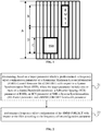
- Mode 1 the time division multiplexing manner of the RMSI CORESET and the associated SSB is shown in FIG.
- A is the carrier bandwidth and has a granularity of RMSI RB (Resource Block);
- B is the bandwidth occupied by the RMSI CORESET at a granularity of RMSI RB;
- C is the bandwidth occupied by the SSB at a granularity of SSB RB;
- D is a frequency domain offset indication of RMSI CORESET relative to SSB, with a granularity of RMSI RB.
- the carrier bandwidth used in designing frequency offset settings for a radio frequency band will be greater than or equal to the minimum bandwidth specified for that radio frequency band.
- the SCS of the RMSI may be the same as or different from the SCS of the associated SSB.
- a key point in the RMSI CORESET configuration design is how to configure the frequency offset between the RMSI CORESET and the associated SSB, i.e. how to configure the difference between the minimum RB index of the SSB and the minimum RB index of the RMSI CORESET, corresponding to parameter D in FIG. 1 .
- SSB subcarrier spacing SCS, Subcarrier Spacing
- RMSI CORESET SCS RMSI CORESET SCS
- Tables 13-1 to 13-8 in 3GPP protocol standard TS 38.213 [2] have given the frequency offset configuration between the RMSI CORESET and the associated SSB supporting the combination of SSB SCS and RMSI CORSET SCS above.
- a technical issue to be solved by the present disclosure is to provide a configuring system information method and device, so as to solve an issue in the related art that the frequency offset configuration of a RMSI CORESET with respect to an SSB is not fully considered.
- a system information configuration method is provided in the present disclosure, including:
- the determining based on the target parameter which is predetermined the frequency offset configuration parameter of the RMSI CORESET with respect to the SSB includes:
- the determining based on the target parameters corresponding to the carrier frequency bands in different frequency ranges the frequency offset configuration parameters of the carrier frequency bands in different frequency ranges includes: determining the frequency offset configuration parameters of the carrier frequency bands in different frequency ranges, based on the target parameters corresponding to the carrier frequency bands in different frequency ranges under conditions of SS Raster definitions in different carrier frequency bands, different combinations of RMSI SCS and SSB SCS and different minimum channel bandwidths.
- the carrier frequency bands in different frequency ranges include a carrier frequency band in a frequency range of 0 to 2.65GHz and/or a carrier frequency band in a frequency range of 2.4 GHz to 6GHz; a minimum channel bandwidth of the carrier frequency band in the frequency range of 0 to 2.65GHz includes 5 MHz, 10 MHz and/or 20 MHz; a minimum channel bandwidth of the carrier frequency band in the frequency range of 2.4 GHz to 6GHz includes 10 MHz, 20 MHz, and/or 40MHz.
- the minimum channel bandwidth of the carrier frequency band in the frequency range of 0 to 2.65GHz includes 5 MHz and 10 MHz, and the same frequency offset configuration table at the minimum channel bandwidths of 5 MHz and 10 MHz is used for the carrier frequency bands in the frequency range of 0 to 2.65GHz.
- the frequency offset configuration parameter includes a candidate frequency offset quantity and a frequency offset; the determining, based on the target parameter which is predetermined, the frequency offset configuration parameter of the RMSI CORESET with respect to the SSB includes:
- the channel bandwidth parameter includes a quantity of Resource Blocks (RBs) within a channel bandwidth
- the RMSI CORESET bandwidth parameter includes a quantity of RBs within a RMSI CORESET bandwidth
- the SS Raster parameter includes an SS Raster interval
- the method further includes: determining the initial offset O 0 , based on the quantity N RMSI of RBs in the granularity of RMSI RB in the RMSI CORESET bandwidth, the candidate frequency offset quantity P and the frequency offset step size ⁇ RMSI and the rule of aligning the SSB with the center of the RMSI CORESET.
- a system information configuration device is further provided in the present disclosure, including:
- a system information configuration device including a transceiver, a memory, a processor and a computer program stored in the memory and executable on the processor; the processor is configured to read a program in the memory to:
- the processor is configured to read the program in the memory to:
- the processor is configured to read the program in the memory to: determine the frequency offset configuration parameters of the carrier frequency bands in different frequency ranges, based on the target parameters corresponding to the carrier frequency bands in different frequency ranges under conditions of SS Raster definitions in different carrier frequency bands, different combinations of RMSI SCS and SSB SCS and different minimum channel bandwidths.
- the carrier frequency bands in different frequency ranges include a carrier frequency band in a frequency range of 0 to 2.65GHz and/or a carrier frequency band in a frequency range of 2.4 GHz to 6GHz; a minimum channel bandwidth of the carrier frequency band in the frequency range of 0 to 2.65GHz includes 5 MHz, 10 MHz and/or 20 MHz; a minimum channel bandwidth of the carrier frequency band in the frequency range of 2.4 GHz to 6GHz includes 10 MHz, 20 MHz, and/or 40MHz.
- the minimum channel bandwidth of the carrier frequency band in the frequency range of 0 to 2.65GHz includes 5 MHz and 10 MHz, and the same frequency offset configuration table at the minimum channel bandwidths of 5 MHz and 10 MHz is used for the carrier frequency bands in the frequency range of 0 to 2.65GHz.
- the frequency offset configuration parameter includes a candidate frequency offset quantity and a frequency offset;
- the processor is configured to read the program in the memory to:
- the channel bandwidth parameter includes a quantity of Resource Blocks (RBs) within a channel bandwidth
- the RMSI CORESET bandwidth parameter includes a quantity of RBs within a RMSI CORESET bandwidth
- the SS Raster parameter includes an SS Raster interval
- the processor is configured to read the program in the memory to:
- the processor is configured to read the program in the memory to: determine the initial offset O 0 , based on the quantity N RMSI of RBs in the granularity of RMSI RB in the RMSI CORESET bandwidth, the candidate frequency offset quantity P and the frequency offset step size ⁇ RMSI and the rule of aligning the SSB with the center of the RMSI CORESET.
- a computer readable storage medium is further provided in the present disclosure, where a computer program is stored in the computer readable storage medium, the computer program is executed by a processor to perform the system information configuration method hereinabove.
- a frequency offset configuration parameter of the RMSI CORESET with respect to the SSB is first determined based on a predetermined target parameter;
- the target parameters include one or more of channel bandwidth parameters, SCS parameters of RMSI, SCS parameters of SSB, SS Raster parameters, and RMSI CORESET bandwidth parameters; the frequency offset configuration of the RMSI CORESET with respect to the SSB is then performed according to the frequency offset configuration parameters.
- the frequency offset configuration of the RMSI CORESET with respect to the SSB is performed by combining factors such as the combination of the RMSI SCS and the SSB SCS, the channel bandwidth, the SS Raster, and the RMSI CORESET bandwidth.
- the protocol configuration method is improved, the correctness of the protocol configuration is ensured, and the problem that the frequency offset configuration in the related art is not considered comprehensively is solved.
- a system information configuration method is provided with reference to FIG. 2 , including:
- the frequency offset configuration of the RMSI CORESET with respect to the SSB is performed by combining factors such as RMSI SCS and SSB SCS combination, channel bandwidth, SS Raster, and RMSI CORESET bandwidth.
- the protocol configuration method is improved, and correctness of the protocol configuration is ensured.
- RMSI CORESET only RMSI CORESET is referred to, and if not specifically described RMSI all refer to RMSI CORESET.
- the step 21 includes: Step 211: determining, based on the target parameters corresponding to carrier frequency bands in different frequency ranges, the frequency offset configuration parameters of the carrier frequency bands in different frequency ranges.
- the frequency offset configuration parameters of the carrier frequency bands of the different frequency ranges are determined according to the target parameters corresponding to the carrier frequency bands of the different frequency ranges, so that a frequency offset configuration is performed independently on each of the carrier frequency bands of the different frequency ranges.
- Step 22 includes: Step 222: performing the frequency offset configuration of the RMSI CORESET with respect to the SSB for the carrier frequency bands in different frequency ranges based on the frequency offset configuration parameters of the carrier frequency bands in different frequency ranges, to obtain frequency offset configuration tables corresponding to the carrier frequency bands in different frequency ranges.
- the frequency offset configuration is separately performed on the carrier frequency bands in the different frequency ranges, and a frequency offset configuration table corresponding to the carrier frequency bands in the different frequency ranges is obtained.
- the carrier frequency bands of the different frequency ranges may include, but are not limited to, a carrier frequency band in a frequency range of 0 to 2.65GHz and/or a carrier frequency band in a frequency range of 2.4 GHz to 6GHz, for example.
- step 211 includes: Step 2111: determining the frequency offset configuration parameters of the carrier frequency bands in different frequency ranges, based on the target parameters corresponding to the carrier frequency bands in different frequency ranges under conditions of SS Raster definitions in different carrier frequency bands, different combinations of RMSI SCS and SSB SCS and different minimum channel bandwidths.
- the SS Raster definition in different carrier frequency bands, the combination of different RMSI SCS and SSB SCS, and the conditions of different minimum channel bandwidths are considered, and the frequency offset configuration parameters are determined by using the target parameters corresponding to the carrier frequency bands in different frequency ranges under these conditions, and then the RMSI CORESET frequency offset configuration is performed based on the frequency offset configuration parameters, so that all the RMSI CORESET frequency offset configurations are realized.
- the protocol configuration method is improved, and the correctness of the protocol configuration is ensured.
- the carrier frequency bands of the different frequency ranges include a carrier frequency band in a frequency range of 0 to 2.65GHz and/or a carrier frequency band in a frequency range of 2.4 GHz to 6GHz;
- the minimum channel bandwidth of the carrier frequency band ranging from 0 to 2.65GHz includes 5 MHz, 10 MHz and/or 20 MHz;
- the minimum channel bandwidth of the carrier frequency band ranging from 2.4 GHz to 6GHz includes 10 MHz, 20 MHz, and/or 40MHz.
- the frequency offset configuration parameters of the carrier frequency band of the [0-2.65GHz] can be obtained based on the target parameters corresponding to the carrier frequency band of the [0-2.65GHz] at the minimum channel bandwidths of 5 MHz, 10 MHz, and 20 MHz, and the SS Raster definitions in different carrier frequency bands, and different combinations of RMSI SCS and SSB SCS, respectively, so that the offset configuration table of the carrier frequency band of the [0-2.65GHz] can be obtained.
- the frequency offset configuration parameters of the carrier frequency band of the [2.4GHz-6GHz] can be obtained according to the target parameters corresponding to the carrier frequency band of the [2.4GHz-6GHz] in the minimum channel bandwidths of 10 MHz, 20 MHz, and 40MHz, and the SS Raster definitions in different carrier frequency bands, and different combinations of RMSI SCS and SSB SCS, respectively, and the offset configuration table of the carrier frequency band of the [2.4GHz-6GHz] can be further obtained.
- some embodiments of the present disclosure add a frequency offset configuration table for a frequency range of [2.4, 6 GHz] and a minimum channel bandwidth of 40MHz bands.
- the minimum channel bandwidth of the carrier frequency band in a frequency range of 0 to 2.65GHz includes 5 MHz and 10 MHz, and the carrier frequency band in a frequency range of 0 to 2.65GHz uses the same frequency offset configuration table at the minimum channel bandwidths of 5 MHz and 10 MHz.
- the same frequency offset configuration table can be used at the minimum channel bandwidths of 5 MHz and 10 MHz by a reasonable design.
- the frequency offset configuration parameter includes a quantity of candidate frequency offsets and a frequency offset.
- Step 21 includes: Step 212, determining the candidate frequency offset quantity and the frequency offset based on the target parameter which is predetermined and a predetermined rule, where the predetermined rule includes one or more of a rule of minimizing all possible quantities of candidate frequency offset positions within one SS Raster interval and a rule of aligning the SSB with a center of the RMSI CORESET.
- the channel bandwidth parameter includes a quantity of Resource Blocks (RBs) within a channel bandwidth
- the RMSI CORESET bandwidth parameter includes a quantity of RBs within a RMSI CORESET bandwidth
- the SS Raster parameter includes an SS Raster interval.
- Step 212 includes step 2121-2124: Step 2121: determining, based on the quantity of RBs within the channel bandwidth and the quantity of RBs within the RMSI CORESET bandwidth, a maximum quantity of positions of the SSB supportable by each offset value in a configuration.
- Step 2122 determining, based on the SS Raster interval and a maximum quantity of RB positions possible for placing SS Rasters in the channel bandwidth and according to the rule of minimizing all possible quantities of candidate frequency offset positions within one SS Raster interval, a maximum quantity of candidate RB positions possible for placing the SS Rasters in the channel bandwidth.
- the maximum quantity of candidate RB positions at which the SS Raster may be placed in the channel bandwidth to be considered corresponds to the number N of possible SSB positions at which the SS Raster may be placed in the channel bandwidth to be considered.
- N depends on the following two values: A) SS Raster interval; B) Maximum number of RB positions within the channel bandwidth where SS Raster may be placed.
- the quantity P of subsequent frequency offsets required for the RMSI CORESET configuration is equal to the maximum quantity N of candidate RB positions within the channel bandwidth where SS Raster may be placed, divided by the maximum quantity of positions ⁇ SSB where each offset value in the previous configuration may support SSB, and then rounded up.
- Step 2124 determining a candidate set of frequency offsets, based on the candidate frequency offset quantity, the maximum quantity of positions of the SSB supportable by each offset value in the configuration and a predefined initial offset.
- the frequency offset step size ⁇ RMSI is calculated from the scaling factor between the SCS of the SSB and the SCS of the RMSI, and the value of ⁇ RMSI uses RMSI RB as the granularity. Since the granularity size is SSB RB, ⁇ SSB is multiplied by 2 ⁇ ⁇ to be converted to ⁇ RMSI .
- the SSB and RMSI CORESET should be designed to meet the as central alignment rule as possible so as to ensure that the frequency-domain channel responses of the RMSI and the SSB are substantially equal when the bandwidth of the RMSI is large, to ensure the frequency-domain QCL relationship.
- the method further comprises: Step 23: determining the initial offset O 0 , based on the quantity N RMSI of RBs in the granularity of RMSI RB in the RMSI CORESET bandwidth, the candidate frequency offset quantity P and the frequency offset step size ⁇ RMSI and the rule of aligning the SSB with the center of the RMSI CORESET.
- the initial offset O 0 is determined based on the rule of alignment of the SSB and the center of the RMSI CORESET.
- the bandwidth of the RMSI CORESET is large, it is possible to ensure that the frequency-domain channel responses of the RMSI CORESET and the SSB are substantially equal, so as to ensure the frequency-domain QCL relationship.
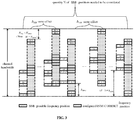
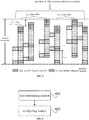
- FIG. 3 , FIG. 4 , and FIG. 5 are schematic views of frequency offset configuration using the above-described system information configuration methods of some embodiments of the present disclosure in three typical scenarios, respectively.
- SCS SSB 2
- the RMSI CORESET frequency offset configuration table of the NR band in which the carrier frequency is lower than 6GHz, which is generated using the above-described system information configuration method in some embodiments of the present disclosure, will be described as an example.
- Table 1 below provides different channel bandwidths to be considered when designing frequency offsets in some embodiments of the present disclosure, the quantity of channel bandwidths RB (Resource Block, resource blocks) at different channel bandwidths for different SCS (granularity is RMSI RB), and the quantity of RMSI CORESET bandwidths RB to be considered when designing frequency offsets (granularity is RMSI RB).
- Table 1 SCS (kHz) Channel bandwidth (MHz) Channel bandwidth RB Number N BW (RBs) RMSI CORESET bandwidth RB number N RMSI (RBs) 15 5 25 24 10 52 48 20 106 96 30 10 24 24 20 51 48 40 106 96 with respect to the SS Raster parameter: In the frequency range of [0-2.65GHz], the frequency band having the minimum channel bandwidth of 5 MHz, the defined SS Raster interval is 900kHz.
- the frequency band having the minimum channel bandwidth of 10 MHz the defined SS Raster interval is 1800kHz.
- the SS Raster interval is 4.32MHz, meaning that one RB in every 24 SSB RB can place SS Raster, i.e.:
- Tables 2 to 4, 5a and 5b give frequency offset configuration parameters when ⁇ SSB SCS, RMSI SCS ⁇ is ⁇ 15,15 ⁇ kHz, ⁇ 15,30 ⁇ kHz, ⁇ 30,15 ⁇ kHz, ⁇ 30,30 ⁇ kHz, respectively.
- the frequency offset configuration parameters corresponding to the first three items in Tables 2 to 4 and 5a (a frequency band in which the [0-2.65GHz] minimum channel bandwidth is 5 MHz, a frequency band in which the [0-2.65GHz] minimum channel bandwidth is 10 MHz, and a frequency band in which the [2.4-6GHz] minimum channel bandwidth is 10 MHz) and the frequency offset configuration parameters in Table 5b are calculated based on the flow chart for determining the frequency offset configuration parameters, Table 1, and the above SS Raster parameter information in the above system information configuration methods of some embodiments of the present disclosure.
- the configuration parameters of Table 13-1 or Table 13-2 from TS 38.213 [1] are also compared in Table 2 to Table 4, Table 5a. where N/A represents no value.
- Table 2 Frequency offset configuration when ⁇ SSB SCS, RMSI SCS ⁇ is ⁇ 15,15 ⁇ kHz Name [0-2.65GHz] Frequency band with a minimum channel bandwidth of 5 MHz [0-2.65GHz] Frequency band with a minimum channel bandwidth of 10 MHz [2.4-6GHz] Frequency band with a minimum channel bandwidth of 10 MHz Table 13 & # x2212; 1 from TS 38.213 [1] N Sync (RB) 5 10 24 - Channel Bandwidth (MHz) 5 10 20 10 20 10 20 5 10 20 Number of channel bandwidth RBs N BW 25 52 106 52 106 52 106 25 52 106 Number of RMSI CORESET Bandwidth RBs N RMSI 24 48 96 48 96 48 96 24 48 96 Frequency offset step ⁇ RMSI 2 N/A N/A 5 N/A 5 11 2 4 N/A Number of candidate frequency offsets P 3 1 1 2 1 5 3 3 2 1 Initial offset O 0 0 14 38 11 38 4 27
- the frequency offset configuration parameters of Table 13-1 of TS 38.213 [1] are consistent with the frequency offset configuration parameters obtained using the method in some embodiments of the present disclosure when the channel bandwidths are 5 MHz and 20 MHz, but when the channel bandwidth is 10 MHz, the method in some embodiments of the present disclosure requires only one offset number, and table 13-1 of TS 38.213 [1] obviously does not take into account the scenario where the minimum channel bandwidth is 10 MHz, while in some embodiments of the present disclosure the frequency offset configuration parameters for the frequency band where the minimum channel bandwidth of [0-2.65GHz] is 10 MHz are also given.
- the method in some embodiments of the present disclosure is jointly designed taking into account combinations of different SSB SCS and RMSI SCS, different channel bandwidths, different SS Raster definitions in different carrier bands, and different RMSI CORESET bandwidths.
- a separate frequency offset configuration table is used for each of the carrier frequency band in the [0-2.65GHz] frequency range and the carrier frequency band in the [2.4GHz-6GHz] frequency range.
- the minimum channel bandwidths of 5 MHz and 10 MHz are configured using the same frequency offset table by a reasonable design.
- Table 5a, ⁇ SSB SCS, RMSI SCS ⁇ is exemplified as ⁇ 30, 30 ⁇ kHz.
- the candidate sets of required frequency offsets according to Table 5a are ⁇ 0, 1, 2, 3, 4 ⁇ and ⁇ 12, 18 ⁇ , respectively, for the RMSI CORESET bandwidth RB numbers N RMSI being 24RBs and 48RBs.
- the candidate set of required frequency offsets according to Table 5a is ⁇ 1, 2, 3 ⁇ .
- the frequency offset at a minimum channel bandwidth of 10 MHz already includes all the frequency offsets required at a minimum channel bandwidth of 5 MHz.
- Table 13-1 to Table 13-4 can be modified based on the method in some embodiments of the present disclosure for the frequency range of [0-2.65 GHz], with the minimum channel bandwidth of 5 MHz and 10 MHz frequency offset using the same configuration table.
- Table 13-1, Table 13-2, Table 13-3 and Table 13-4 in the modified TS 38.213 are shown in Tables 6 to 9 below.
- a frequency offset configuration table used for a frequency band having a minimum channel bandwidth of 10 MHz in the frequency range of [2.4-6GHz] is added, as shown in Tables 10 to 13.
- the minimum channel bandwidth is 40MHz, and the SS Raster interval is 30.24MHz.
- the SCS is 30kHz, only one RB can place SS Raster per 84 SSB RB.
- the frequency offset configuration values used may be as shown in Table 13. Unlike the frequency range of [2.4-6GHz], where the minimum channel bandwidth is a frequency band of 10 MHz, we recommend increasing in TS 38.213 the frequency offset configuration table for the frequency range of [2.4-6GHz] where the minimum channel bandwidth is a 40MHz frequency band and ⁇ SSB SCS, RMSI SCS ⁇ is ⁇ 30,30 ⁇ kHz, as shown in Table 14.
- Tables 8 and 12 can be combined into one table, Table 15.
- Tables 9 and 13 may well be combined into one table, Table 16.
- Table 6 (TS 38.213 Table 13-1): For the frequency band of the [0-2.65GHz] frequency range, when the subcarrier spacing of ⁇ SS/PBCH block, PDCCH ⁇ is ⁇ 15, 15 ⁇ kHz, the slot symbols of the RBs set and CORESET for the type 0-PDCCH search space.
- some embodiments of the present disclosure provide a systematic system information configuration method for designing all RMSI CORESET configurations based on a rule of minimizing all possible quantities of candidate frequency offset positions within a SS Raster interval, and a rule of aligning the SSB with the RMSI CORESET center, given a combination of carrier frequency bands, channel bandwidths, SSB SCS, and RMSI SCS.
- the method according to the embodiment of the present invention is used to modify and redesign the existing configuration method in the 3GPP protocol standard, thereby ensuring the correctness of the protocol configuration method.
- a system information configuration device is also provided in an embodiment of the present disclosure, including:
- the frequency offset configuration of the RMSI CORESET with respect to the SSB is performed by combining factors such as the combination of the RMSI SCS and the SSB SCS, the channel bandwidth, the SS Raster, and the RMSI CORESET bandwidth.
- the protocol configuration method is improved, and correctness of the protocol configuration is ensured.
- the first determining module 601 includes: a first determining submodule, configured to determine, based on the target parameters corresponding to carrier frequency bands in different frequency ranges, the frequency offset configuration parameters of the carrier frequency bands in different frequency ranges;
- the configuration module 602 includes: a first configuring submodule, configured to perform the frequency offset configuration of the RMSI CORESET with respect to the SSB for the carrier frequency bands in different frequency ranges based on the frequency offset configuration parameters of the carrier frequency bands in different frequency ranges, to obtain frequency offset configuration tables corresponding to the carrier frequency bands in different frequency ranges.
- the first determining submodule comprises: a first determining unit, configured to determine the frequency offset configuration parameters of the carrier frequency bands in different frequency ranges, based on the target parameters corresponding to the carrier frequency bands in different frequency ranges under conditions of SS Raster definitions in different carrier frequency bands, different combinations of RMSI SCS and SSB SCS and different minimum channel bandwidths.
- the carrier frequency bands in different frequency ranges include a carrier frequency band in a frequency range of 0 to 2.65GHz and/or a carrier frequency band in a frequency range of 2.4 GHz to 6GHz; a minimum channel bandwidth of the carrier frequency band in the frequency range of 0 to 2.65GHz includes 5 MHz, 10 MHz and/or 20 MHz; a minimum channel bandwidth of the carrier frequency band in the frequency range of 2.4 GHz to 6GHz includes 10 MHz, 20 MHz, and/or 40MHz.
- the minimum channel bandwidth of the carrier frequency band in the frequency range of 0 to 2.65GHz includes 5 MHz and 10 MHz, and the same frequency offset configuration table at the minimum channel bandwidths of 5 MHz and 10 MHz is used for the carrier frequency bands in the frequency range of 0 to 2.65GHz.
- the frequency offset configuration parameter includes a candidate frequency offset quantity and a frequency offset.
- the first determining module 601 includes: a second determining submodule configured to determine the candidate frequency offset quantity and the frequency offset based on the target parameter which is predetermined and a predetermined rule, where the predetermined rule includes one or more of a rule of minimizing all possible quantities of candidate frequency offset positions within one SS Raster interval and a rule of aligning the SSB with a center of the RMSI CORESET.
- the channel bandwidth parameter includes a quantity of Resource Blocks (RBs) within a channel bandwidth
- the RMSI CORESET bandwidth parameter includes a quantity of RBs within a RMSI CORESET bandwidth
- the SS Raster parameter includes an SS Raster interval.
- the second determining submodule includes:
- the third determining unit includes:
- the fifth determining unit includes:
- the device further includes: a second determining module, configured to determine the initial offset O 0 , based on the quantity N RMSI of RBs in the granularity of RMSI RB in the RMSI CORESET bandwidth, the candidate frequency offset quantity P and the frequency offset step size ⁇ RMSI and the rule of aligning the SSB with the center of the RMSI CORESET.
- a second determining module configured to determine the initial offset O 0 , based on the quantity N RMSI of RBs in the granularity of RMSI RB in the RMSI CORESET bandwidth, the candidate frequency offset quantity P and the frequency offset step size ⁇ RMSI and the rule of aligning the SSB with the center of the RMSI CORESET.
- the frequency offset configuration of the RMSI CORESET with respect to the SSB is performed by combining factors such as the combination of the RMSI SCS and the SSB SCS, the channel bandwidth, the SS Raster, and the RMSI CORESET bandwidth.
- the protocol configuration method is improved, and correctness of the protocol configuration is ensured.
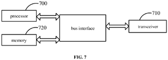
- a system information configuration device including a transceiver 710, a memory 720, a processor 700, a bus interface, and a computer program stored in the memory 720 and executable on the processor 700;
- the processor 700 is configured to read a program in a memory to determine, based on a target parameter which is predetermined, a frequency offset configuration parameter of a Remaining Minimum System Information (RMSI) Control Resource Set (CORESET) with respect to a System Synchronization Block (SSB), where the target parameter includes one or more of a channel bandwidth parameter, a Subcarrier Spacing (SCS) parameter of RMSI, an SCS parameter of SSB, a System Synchronization (SS) Raster parameter, and a RMSI CORESET bandwidth parameter; and perform a frequency offset configuration of the RMSI CORESET with respect to the SSB according to the frequency offset configuration parameter.
- RMSI Remaining Minimum System Information
- CORESET Control Resource Set
- SSB System Synchronization Block
- the frequency offset configuration of the RMSI CORESET with respect to the SSB is performed by combining factors such as the combination of the RMSI SCS and the SSB SCS, the channel bandwidth, the SS Raster, and the RMSI CORESET bandwidth.
- the protocol configuration method is improved, and correctness of the protocol configuration is ensured.
- the bus architecture may include any number of interconnected buses and bridges, specifically, the various circuits of one or more processors represented by the processor 700 and the memory represented by the memory 720 are linked together.
- the bus architecture may also link various other circuits, such as peripherals, voltage regulators, and power management circuits, all of which are well known in the art and therefore will not be described further herein.
- the bus interface provides an interface.
- Transceiver 710 may be a plurality of elements, including a transmitter and a transceiver, providing units for communicating with various other devices on a transmission medium.
- the processor 700 is responsible for managing the bus architecture and general processing, and the memory 720 may store data used by the processor 700 in performing operations.
- the processor 700 is configured to read the program in the memory to:
- the processor 700 is configured to read the program in the memory to: determine the frequency offset configuration parameters of the carrier frequency bands in different frequency ranges, based on the target parameters corresponding to the carrier frequency bands in different frequency ranges under conditions of SS Raster definitions in different carrier frequency bands, different combinations of RMSI SCS and SSB SCS and different minimum channel bandwidths.
- the carrier frequency bands in different frequency ranges include a carrier frequency band in a frequency range of 0 to 2.65GHz and/or a carrier frequency band in a frequency range of 2.4 GHz to 6GHz; a minimum channel bandwidth of the carrier frequency band in the frequency range of 0 to 2.65GHz includes 5 MHz, 10 MHz and/or 20 MHz; a minimum channel bandwidth of the carrier frequency band in the frequency range of 2.4 GHz to 6GHz includes 10 MHz, 20 MHz, and/or 40MHz.
- the minimum channel bandwidth of the carrier frequency band in the frequency range of 0 to 2.65GHz includes 5 MHz and 10 MHz, and the same frequency offset configuration table at the minimum channel bandwidths of 5 MHz and 10 MHz is used for the carrier frequency bands in the frequency range of 0 to 2.65GHz.
- the frequency offset configuration parameter includes a candidate frequency offset quantity and a frequency offset;
- the processor 700 is configured to read the program in the memory to:
- the channel bandwidth parameter includes a quantity of Resource Blocks (RBs) within a channel bandwidth
- the RMSI CORESET bandwidth parameter includes a quantity of RBs within a RMSI CORESET bandwidth
- the SS Raster parameter includes an SS Raster interval
- the processor 700 is configured to read the program in the memory to:
- the processor 700 is configured to read the program in the memory to: determine the initial offset O 0 , based on the quantity N RMSI of RBs in the granularity of RMSI RB in the RMSI CORESET bandwidth, the candidate frequency offset quantity P and the frequency offset step size ⁇ RMSI and the rule of aligning the SSB with the center of the RMSI CORESET.
- a computer readable storage medium storing a computer program is further provided, the computer program is executed by a processor to:
- the processor is configured to read the program in the memory to:
- the processor is configured to read the program in the memory to: determine the frequency offset configuration parameters of the carrier frequency bands in different frequency ranges, based on the target parameters corresponding to the carrier frequency bands in different frequency ranges under conditions of SS Raster definitions in different carrier frequency bands, different combinations of RMSI SCS and SSB SCS and different minimum channel bandwidths.
- the carrier frequency bands in different frequency ranges include a carrier frequency band in a frequency range of 0 to 2.65GHz and/or a carrier frequency band in a frequency range of 2.4 GHz to 6GHz; a minimum channel bandwidth of the carrier frequency band in the frequency range of 0 to 2.65GHz includes 5 MHz, 10 MHz and/or 20 MHz; a minimum channel bandwidth of the carrier frequency band in the frequency range of 2.4 GHz to 6GHz includes 10 MHz, 20 MHz, and/or 40MHz.
- the minimum channel bandwidth of the carrier frequency band in the frequency range of 0 to 2.65GHz includes 5 MHz and 10 MHz, and the same frequency offset configuration table at the minimum channel bandwidths of 5 MHz and 10 MHz is used for the carrier frequency bands in the frequency range of 0 to 2.65GHz.
- the frequency offset configuration parameter includes a candidate frequency offset quantity and a frequency offset
- the processor is configured to read the program in the memory to: determine the candidate frequency offset quantity and the frequency offset based on the target parameter which is predetermined and a predetermined rule; where the predetermined rule includes one or more of a rule of minimizing all possible quantities of candidate frequency offset positions within one SS Raster interval and a rule of aligning the SSB with a center of the RMSI CORESET.
- the channel bandwidth parameter includes a quantity of Resource Blocks (RBs) within a channel bandwidth
- the RMSI CORESET bandwidth parameter includes a quantity of RBs within a RMSI CORESET bandwidth
- the SS Raster parameter includes an SS Raster interval
- the processor is configured to read the program in the memory to:
- the processor is configured to read the program in the memory to: determine the initial offset O 0 , based on the quantity N RMSI of RBs in the granularity of RMSI RB in the RMSI CORESET bandwidth, the candidate frequency offset quantity P and the frequency offset step size ⁇ RMSI and the rule of aligning the SSB with the center of the RMSI CORESET.
Landscapes
- Engineering & Computer Science (AREA)
- Signal Processing (AREA)
- Computer Networks & Wireless Communication (AREA)
- Computer Security & Cryptography (AREA)
- Physics & Mathematics (AREA)
- Mathematical Physics (AREA)
- Digital Transmission Methods That Use Modulated Carrier Waves (AREA)
- Cable Transmission Systems, Equalization Of Radio And Reduction Of Echo (AREA)
- Mobile Radio Communication Systems (AREA)
- Hardware Redundancy (AREA)
- Two-Way Televisions, Distribution Of Moving Picture Or The Like (AREA)
- Magnetic Resonance Imaging Apparatus (AREA)
Abstract
Description
- The present application claims a priority of Chinese patent application No.
201810032494.X filed on January 12, 2018 - The present disclosure relates to the field of communications, and more particularly, to a system information configuration method and device.
- In the 5G NR (New Radio) system, the minimum system information (MSI, Minimum System Information) is the system information necessary for the terminal to make the initial access. A part of the minimum system information is transmitted through PBCH (Physical Broadcast Channel, Physical Broadcast Channel), and the remaining minimum system information (RMSI, Remaining Minimum System Information) is transmitted through PDSCH (Physical Downlink Shared Channel, Physical Downlink Shared Channel). In addition, the PDSCH transmitting the RMSI is scheduled by using a PDCCH (Physical Downlink Control Channel, physical downlink control channel). The PDCCH (PDSCH used to schedule the bearer RMSI) is indicated by RMSI control resource set (CORESET, Control Resource Set) configuration information. The RMSI CORESET configuration information belongs to the minimum system information and is transmitted on the PBCH channel.
- Each RMSI CORESET is associated with a system synchronization block (SSB, System Synchronization Block). The RMSI CORESET and the SSB have two multiplexing modes, frequency division multiplexing (FDM, Frequency Division Multiplexing) or time division multiplexing (TDM, Time Division Multiplexing), respectively. Here, the time division multiplexing means that the RMSI CORESET and the associated SSB are transmitted on different OFDM (Orthogonal Frequency Division Multiplexing) symbols in the time domain. The time division multiplexing mode must be supported when the system cannot support the frequency division multiplexing mode.
- NR supports different multiplexing modes between SSB and RMSI CORESET. The time division multiplexing mode is also referred to as "
Mode 1"; [1, and 2] refers to a multiplexing mode in which SSB and RMSI CORESET occur at different times. For time division multiplexing "Mode 1", the time division multiplexing manner of the RMSI CORESET and the associated SSB is shown inFIG. 1 , where "A" is the carrier bandwidth and has a granularity of RMSI RB (Resource Block); "B" is the bandwidth occupied by the RMSI CORESET at a granularity of RMSI RB; "C" is the bandwidth occupied by the SSB at a granularity of SSB RB; "D" is a frequency domain offset indication of RMSI CORESET relative to SSB, with a granularity of RMSI RB. The carrier bandwidth used in designing frequency offset settings for a radio frequency band will be greater than or equal to the minimum bandwidth specified for that radio frequency band. Each RMSI RB and SSB RB uses a bandwidth equal to 12 times the bandwidth of their respective SCS. For example, when SCS=15kHz, one RB uses a bandwidth of 180kHz. The SCS of the RMSI may be the same as or different from the SCS of the associated SSB. - A key point in the RMSI CORESET configuration design is how to configure the frequency offset between the RMSI CORESET and the associated SSB, i.e. how to configure the difference between the minimum RB index of the SSB and the minimum RB index of the RMSI CORESET, corresponding to parameter D in
FIG. 1 . - In the 3GPP RAN1#91 meeting, it has been determined that the following combinations of SSB SCS and RMSI CORSET SCS are supported:
- combinations under 6GHz include: {SS SCS, RMSI SCS} = {15,15} kHz, {15,30} kHz, {30,15} kHz, {30,30} kHz;
- combinations above 6GHz include: {SS SCS, RMSI SCS} = {120, 60} kHz, {120,120} kHz, {240, 60} kHz, {240,120} kHz.
- For any combination of SSB subcarrier spacing (SCS, Subcarrier Spacing) and RMSI CORESET SCS, it is desirable to support as many RMSI CORESET configurations as possible from a system design point of view. However, the NR protocol specifies that only 4 bits in the PBCH can be used to indicate the frequency offset between the start position of the RMSI CORESET and the start position of the associated SSB, i.e. a total of only 2^4=16 cases can be indicated.
- Tables 13-1 to 13-8 in 3GPP protocol standard TS 38.213 [2] have given the frequency offset configuration between the RMSI CORESET and the associated SSB supporting the combination of SSB SCS and RMSI CORSET SCS above.
- However, due to the limitation of meeting time in the related art, the consideration of the frequency offset configuration for RMSI CORESET with respect to SSB in Tables 13-1 to 13-8 in TS38.213 [2] is not comprehensive. In particular, the effects of factors such as a SS Raster and a minimum channel bandwidth are not considered for 6GHz or less.
- A technical issue to be solved by the present disclosure is to provide a configuring system information method and device, so as to solve an issue in the related art that the frequency offset configuration of a RMSI CORESET with respect to an SSB is not fully considered.
- A system information configuration method is provided in the present disclosure, including:
- determining, based on a target parameter which is predetermined, a frequency offset configuration parameter of a Remaining Minimum System Information (RMSI) Control Resource Set (CORESET) with respect to a System Synchronization Block (SSB), where the target parameter includes one or more of a channel bandwidth parameter, a Subcarrier Spacing (SCS) parameter of RMSI, an SCS parameter of SSB, a System Synchronization (SS) Raster parameter, and a RMSI CORESET bandwidth parameter; and
- performing a frequency offset configuration of the RMSI CORESET with respect to the SSB according to the frequency offset configuration parameter.
- Optionally, the determining based on the target parameter which is predetermined the frequency offset configuration parameter of the RMSI CORESET with respect to the SSB includes:
- determining, based on the target parameters corresponding to carrier frequency bands in different frequency ranges, the frequency offset configuration parameters of the carrier frequency bands in different frequency ranges;
- performing the frequency offset configuration of the RMSI CORESET with respect to the SSB according to the frequency offset configuration parameter includes:
- performing the frequency offset configuration of the RMSI CORESET with respect to the SSB for the carrier frequency bands in different frequency ranges based on the frequency offset configuration parameters of the carrier frequency bands in different frequency ranges, to obtain frequency offset configuration tables corresponding to the carrier frequency bands in different frequency ranges.
- Optionally, the determining based on the target parameters corresponding to the carrier frequency bands in different frequency ranges the frequency offset configuration parameters of the carrier frequency bands in different frequency ranges includes:
determining the frequency offset configuration parameters of the carrier frequency bands in different frequency ranges, based on the target parameters corresponding to the carrier frequency bands in different frequency ranges under conditions of SS Raster definitions in different carrier frequency bands, different combinations of RMSI SCS and SSB SCS and different minimum channel bandwidths. - Optionally, the carrier frequency bands in different frequency ranges include a carrier frequency band in a frequency range of 0 to 2.65GHz and/or a carrier frequency band in a frequency range of 2.4 GHz to 6GHz;
a minimum channel bandwidth of the carrier frequency band in the frequency range of 0 to 2.65GHz includes 5 MHz, 10 MHz and/or 20 MHz;
a minimum channel bandwidth of the carrier frequency band in the frequency range of 2.4 GHz to 6GHz includes 10 MHz, 20 MHz, and/or 40MHz. - Optionally, the minimum channel bandwidth of the carrier frequency band in the frequency range of 0 to 2.65GHz includes 5 MHz and 10 MHz, and the same frequency offset configuration table at the minimum channel bandwidths of 5 MHz and 10 MHz is used for the carrier frequency bands in the frequency range of 0 to 2.65GHz.
- Optionally, the frequency offset configuration parameter includes a candidate frequency offset quantity and a frequency offset;
the determining, based on the target parameter which is predetermined, the frequency offset configuration parameter of the RMSI CORESET with respect to the SSB includes: - determining the candidate frequency offset quantity and the frequency offset based on the target parameter which is predetermined and a predetermined rule;
- where the predetermined rule includes one or more of a rule of minimizing all possible quantities of candidate frequency offset positions within one SS Raster interval and a rule of aligning the SSB with a center of the RMSI CORESET.
- Optionally, the channel bandwidth parameter includes a quantity of Resource Blocks (RBs) within a channel bandwidth, the RMSI CORESET bandwidth parameter includes a quantity of RBs within a RMSI CORESET bandwidth, and the SS Raster parameter includes an SS Raster interval;
the determining the candidate frequency offset quantity and the frequency offset based on the target parameter which is predetermined and the predetermined rule includes: - determining, based on the quantity of RBs within the channel bandwidth and the quantity of RBs within the RMSI CORESET bandwidth, a maximum quantity of positions of the SSB supportable by each offset value in a configuration;
- determining, based on the SS Raster interval and a maximum quantity of RB positions possible for placing SS Rasters in the channel bandwidth and according to the rule of minimizing all possible quantities of candidate frequency offset positions within one SS Raster interval, a maximum quantity of candidate RB positions possible for placing the SS Rasters in the channel bandwidth;
- determining the candidate frequency offset quantity, based on the maximum quantity of RB positions possible for placing SS Rasters in the channel bandwidth and the maximum quantity of positions of the SSB supportable by each offset value in the configuration; and
- determining a candidate set of frequency offsets, based on the candidate frequency offset quantity, the maximum quantity of positions of the SSB supportable by each offset value in the configuration and a predefined initial offset.
- Optionally, the determining, based on the quantity of RBs within the channel bandwidth and the quantity of RBs within the RMSI CORESET bandwidth, the maximum quantity of positions of the SSB supportable by each offset value in the configuration includes:
determining the maximum quantity of positions Δ SSB of the SSB supportable by each offset value in the configuration, based on the quantity NBW of RBs in a granularity of RMSI RB within the channel bandwidth and the quantity NRMSI of RBs in a granularity of RMSI RB within the RMSI CORESET bandwidth and through the following formula:
where µ is a scaling factor between the SCS of the SSB and the SCS of the RMSI, and floor represents a rounding down function. - Optionally, the determining, based on the SS Raster interval and the maximum quantity of RB positions possible for placing SS Rasters in the channel bandwidth and according to the rule of minimizing all possible quantities of candidate frequency offset positions within one SS Raster interval, the maximum quantity of candidate RB positions possible for placing the SS Rasters in the channel bandwidth includes:
determining the maximum quantity N' of RB positions possible for placing the SS Rasters in the channel bandwidth, based on the quantity NSSB of RBs in a granularity of SSB RB within the channel bandwidth and through the following formula:
determining the maximum quantity N of candidate RB positions possible for placing the SS Rasters in the channel bandwidth, based on the SS Raster interval N Sync in a granularity of SSB RB and N' and through the following formula:
where min represents a minimum value finding function. - Optionally, the determining the candidate frequency offset quantity, based on the maximum quantity of RB positions possible for placing SS Rasters in the channel bandwidth and the maximum quantity of positions of the SSB supportable by each offset value in the configuration includes:
determining the candidate frequency offset quantity P, based on the maximum quantity N of RB positions possible for placing SS Rasters in the channel bandwidth and the maximum quantity of positions Δ SSB of the SSB supportable by each offset value in the configuration and through the following formula:
where ceiling represents an rounding up function. - Optionally, the determining the candidate set of frequency offsets, based on the candidate frequency offset quantity, the maximum quantity of positions of the SSB supportable by each offset value in the configuration and the predefined initial offset includes:
determining a frequency offset step size Δ RMSI based on the maximum quantity of positions Δ SSB of the SSB supportable by each offset value in the configuration and through the following formula:
where µ is a scaling factor between the SCS of the SSB and the SCS of the RMSI; NRMSI is the quantity of RBs in a granularity of RMSI RB in the RMSI CORESET bandwidth;
determining a value of an ith frequency offset Oi in the candidate set of frequency offsets, based on the candidate frequency offset quantity P, the frequency offset step size Δ RMSI and the predefined initial offset O 0 and through the following formula:
where 1≤i≤P. - Optionally, prior to the determining the value of the ith frequency offset Oi in the candidate set of frequency offsets, based on the candidate frequency offset quantity P, the frequency offset step size Δ RMSI and the predefined initial offset O 0, the method further includes:
determining the initial offset O 0, based on the quantity NRMSI of RBs in the granularity of RMSI RB in the RMSI CORESET bandwidth, the candidate frequency offset quantity P and the frequency offset step size Δ RMSI and the rule of aligning the SSB with the center of the RMSI CORESET. - Optionally, the determining the initial offset O 0, based on the quantity NRMSI of RBs in the granularity of RMSI RB in the RMSI CORESET bandwidth, the candidate frequency offset quantity P and the frequency offset step size Δ RMSI and the rule of aligning the SSB with the center of the RMSI CORESET includes:
determining the initial offset O 0, based on the quantity NRMSI of RBs in the granularity of RMSI RB in the RMSI CORESET bandwidth, the candidate frequency offset quantity P and the frequency offset step size Δ RMSI and the rule of aligning the SSB with the center of the RMSI CORESET and through the following formula:
- A system information configuration device is further provided in the present disclosure, including:
- a determining module, configured to determine, based on a target parameter which is predetermined, a frequency offset configuration parameter of a Remaining Minimum System Information (RMSI) Control Resource Set (CORESET) with respect to a System Synchronization Block (SSB), where the target parameter includes one or more of a channel bandwidth parameter, a Subcarrier Spacing (SCS) parameter of RMSI, an SCS parameter of SSB, a System Synchronization (SS) Raster parameter, and a RMSI CORESET bandwidth parameter; and
- a configuring module, configured to perform a frequency offset configuration of the RMSI CORESET with respect to the SSB according to the frequency offset configuration parameter.
- A system information configuration device is further provided in the present disclosure, including a transceiver, a memory, a processor and a computer program stored in the memory and executable on the processor;
the processor is configured to read a program in the memory to: - determine, based on a target parameter which is predetermined, a frequency offset configuration parameter of a Remaining Minimum System Information (RMSI) Control Resource Set (CORESET) with respect to a System Synchronization Block (SSB), where the target parameter includes one or more of a channel bandwidth parameter, a Subcarrier Spacing (SCS) parameter of RMSI, an SCS parameter of SSB, a System Synchronization (SS) Raster parameter, and a RMSI CORESET bandwidth parameter; and
- perform a frequency offset configuration of the RMSI CORESET with respect to the SSB according to the frequency offset configuration parameter.
- Optionally, the processor is configured to read the program in the memory to:
- determine, based on the target parameters corresponding to carrier frequency bands in different frequency ranges, the frequency offset configuration parameters of the carrier frequency bands in different frequency ranges;
- perform the frequency offset configuration of the RMSI CORESET with respect to the SSB for the carrier frequency bands in different frequency ranges based on the frequency offset configuration parameters of the carrier frequency bands in different frequency ranges, to obtain frequency offset configuration tables corresponding to the carrier frequency bands in different frequency ranges.
- Optionally, the processor is configured to read the program in the memory to:
determine the frequency offset configuration parameters of the carrier frequency bands in different frequency ranges, based on the target parameters corresponding to the carrier frequency bands in different frequency ranges under conditions of SS Raster definitions in different carrier frequency bands, different combinations of RMSI SCS and SSB SCS and different minimum channel bandwidths. - Optionally, the carrier frequency bands in different frequency ranges include a carrier frequency band in a frequency range of 0 to 2.65GHz and/or a carrier frequency band in a frequency range of 2.4 GHz to 6GHz;
a minimum channel bandwidth of the carrier frequency band in the frequency range of 0 to 2.65GHz includes 5 MHz, 10 MHz and/or 20 MHz;
a minimum channel bandwidth of the carrier frequency band in the frequency range of 2.4 GHz to 6GHz includes 10 MHz, 20 MHz, and/or 40MHz. - Optionally, the minimum channel bandwidth of the carrier frequency band in the frequency range of 0 to 2.65GHz includes 5 MHz and 10 MHz, and the same frequency offset configuration table at the minimum channel bandwidths of 5 MHz and 10 MHz is used for the carrier frequency bands in the frequency range of 0 to 2.65GHz.
- Optionally, the frequency offset configuration parameter includes a candidate frequency offset quantity and a frequency offset;
the processor is configured to read the program in the memory to: - determine the candidate frequency offset quantity and the frequency offset based on the target parameter which is predetermined and a predetermined rule;
- where the predetermined rule includes one or more of a rule of minimizing all possible quantities of candidate frequency offset positions within one SS Raster interval and a rule of aligning the SSB with a center of the RMSI CORESET.
- Optionally, the channel bandwidth parameter includes a quantity of Resource Blocks (RBs) within a channel bandwidth, the RMSI CORESET bandwidth parameter includes a quantity of RBs within a RMSI CORESET bandwidth, and the SS Raster parameter includes an SS Raster interval;
the processor is configured to read the program in the memory to: - determine, based on the quantity of RBs within the channel bandwidth and the quantity of RBs within the RMSI CORESET bandwidth, a maximum quantity of positions of the SSB supportable by each offset value in a configuration;
- determine, based on the SS Raster interval and a maximum quantity of RB positions possible for placing SS Rasters in the channel bandwidth and according to the rule of minimizing all possible quantities of candidate frequency offset positions within one SS Raster interval, a maximum quantity of candidate RB positions possible for placing the SS Rasters in the channel bandwidth;
- determine the candidate frequency offset quantity, based on the maximum quantity of RB positions possible for placing SS Rasters in the channel bandwidth and the maximum quantity of positions of the SSB supportable by each offset value in the configuration; and
- determine a candidate set of frequency offsets, based on the candidate frequency offset quantity, the maximum quantity of positions of the SSB supportable by each offset value in the configuration and a predefined initial offset.
- Optionally, the processor is configured to read the program in the memory to:
determine the maximum quantity of positions Δ SSB of the SSB supportable by each offset value in the configuration, based on the quantity NBW of RBs in a granularity of RMSI RB within the channel bandwidth and the quantity NRMSI of RBs in a granularity of RMSI RB within the RMSI CORESET bandwidth and through the following formula:
where µ is a scaling factor between the SCS of the SSB and the SCS of the RMSI, and floor represents a rounding down function. - Optionally, the processor is configured to read the program in the memory to:
determine the maximum quantity N' of RB positions possible for placing the SS Rasters in the channel bandwidth, based on the quantity NSSB of RBs in a granularity of SSB RB within the channel bandwidth and through the following formula:
determine the maximum quantity N of candidate RB positions possible for placing the SS Rasters in the channel bandwidth, based on the SS Raster interval NSync in a granularity of SSB RB and N' and through the following formula:
where min represents a minimum value finding function. - Optionally, the processor is configured to read the program in the memory to:
determine the candidate frequency offset quantity P, based on the maximum quantity N of RB positions possible for placing SS Rasters in the channel bandwidth and the maximum quantity of positions Δ SSB of the SSB supportable by each offset value in the configuration and through the following formula:
where ceiling represents an rounding up function. - Optionally, the processor is configured to read the program in the memory to:
determine a frequency offset step size Δ RMSI based on the maximum quantity of positions Δ SSB of the SSB supportable by each offset value in the configuration and through the following formula:
where µ is a scaling factor between the SCS of the SSB and the SCS of the RMSI; NRMSI is the quantity of RBs in a granularity of RMSI RB in the RMSI CORESET bandwidth;
determine a value of an ith frequency offset Oi in the candidate set of frequency offsets, based on the candidate frequency offset quantity P, the frequency offset step size Δ RMSI and the predefined initial offset O 0 and through the following formula:
where 1≤i≤P. - Optionally, the processor is configured to read the program in the memory to:
determine the initial offset O 0, based on the quantity NRMSI of RBs in the granularity of RMSI RB in the RMSI CORESET bandwidth, the candidate frequency offset quantity P and the frequency offset step size Δ RMSI and the rule of aligning the SSB with the center of the RMSI CORESET. - Optionally, the processor is configured to read the program in the memory to:
determine the initial offset O 0, based on the quantity NRMSI of RBs in the granularity of RMSI RB in the RMSI CORESET bandwidth, the candidate frequency offset quantity P and the frequency offset step size Δ RMSI and the rule of aligning the SSB with the center of the RMSI CORESET and through the following formula:
- A computer readable storage medium is further provided in the present disclosure, where a computer program is stored in the computer readable storage medium, the computer program is executed by a processor to perform the system information configuration method hereinabove.
- Advantageous effects of the above technical solution of the present disclosure are as follows:
According to the system information configuration method according to the present disclosure, a frequency offset configuration parameter of the RMSI CORESET with respect to the SSB is first determined based on a predetermined target parameter; The target parameters include one or more of channel bandwidth parameters, SCS parameters of RMSI, SCS parameters of SSB, SS Raster parameters, and RMSI CORESET bandwidth parameters; the frequency offset configuration of the RMSI CORESET with respect to the SSB is then performed according to the frequency offset configuration parameters. In this way, the frequency offset configuration of the RMSI CORESET with respect to the SSB is performed by combining factors such as the combination of the RMSI SCS and the SSB SCS, the channel bandwidth, the SS Raster, and the RMSI CORESET bandwidth. In consideration, the protocol configuration method is improved, the correctness of the protocol configuration is ensured, and the problem that the frequency offset configuration in the related art is not considered comprehensively is solved. -
-
FIG. 1 is a schematic view of a RMSI CORESET and SSB time division multiplexing mode; -
FIG. 2 is a flowchart of a system information configuration method in some embodiments of the present disclosure; -
FIG. 3 is a schematic view of a frequency offset configuration of a system information configuration method in some embodiments of the present disclosure; -
FIG. 4 is a schematic view of another frequency offset configuration of a system information configuration method in some embodiments of the present disclosure; -
FIG. 5 is a schematic view of another frequency offset configuration of a system information configuration method in some embodiments of the present disclosure; -
FIG. 6 is a schematic view of a system information configuration device in some embodiments of the present disclosure; and -
FIG. 7 is another schematic view of a system information configuration device in some embodiments of the present disclosure. - In order that the technical problems, technical solutions, and advantages to be solved by the present disclosure may be made clearer, reference will now be made in detail to the accompanying drawings and specific examples.
- In some embodiments of the present disclosure, a system information configuration method is provided with reference to
FIG. 2 , including: - Step 21: determining, based on a target parameter which is predetermined, a frequency offset configuration parameter of a Remaining Minimum System Information (RMSI) Control Resource Set (CORESET) with respect to a System Synchronization Block (SSB), where the target parameter includes one or more of a channel bandwidth parameter, a Subcarrier Spacing (SCS) parameter of RMSI, an SCS parameter of SSB, a System Synchronization (SS) Raster parameter, and a RMSI CORESET bandwidth parameter;
- Step 22: performing a frequency offset configuration of the RMSI CORESET with respect to the SSB according to the frequency offset configuration parameter.
- According to the system information configuration method in some embodiments of the present disclosure, the frequency offset configuration of the RMSI CORESET with respect to the SSB is performed by combining factors such as RMSI SCS and SSB SCS combination, channel bandwidth, SS Raster, and RMSI CORESET bandwidth. In consideration of the above, the protocol configuration method is improved, and correctness of the protocol configuration is ensured.
- In some embodiments of the present disclosure, only RMSI CORESET is referred to, and if not specifically described RMSI all refer to RMSI CORESET.
- Optionally, the
step 21 includes:
Step 211: determining, based on the target parameters corresponding to carrier frequency bands in different frequency ranges, the frequency offset configuration parameters of the carrier frequency bands in different frequency ranges. - Here, the frequency offset configuration parameters of the carrier frequency bands of the different frequency ranges are determined according to the target parameters corresponding to the carrier frequency bands of the different frequency ranges, so that a frequency offset configuration is performed independently on each of the carrier frequency bands of the different frequency ranges.
-
Step 22 includes:
Step 222: performing the frequency offset configuration of the RMSI CORESET with respect to the SSB for the carrier frequency bands in different frequency ranges based on the frequency offset configuration parameters of the carrier frequency bands in different frequency ranges, to obtain frequency offset configuration tables corresponding to the carrier frequency bands in different frequency ranges. - Here, according to the frequency offset configuration parameters of the carrier frequency bands in the different frequency ranges, the frequency offset configuration is separately performed on the carrier frequency bands in the different frequency ranges, and a frequency offset configuration table corresponding to the carrier frequency bands in the different frequency ranges is obtained.
- The carrier frequency bands of the different frequency ranges may include, but are not limited to, a carrier frequency band in a frequency range of 0 to 2.65GHz and/or a carrier frequency band in a frequency range of 2.4 GHz to 6GHz, for example.
- At this time, by the above steps 211 and 222, it is possible to obtain a separate frequency offset configuration table for each of the carrier frequency band in the [0-2.65GHz] frequency range and the carrier frequency band in the [2.4GHz-6GHz] frequency range.
- Since the TS 38.213 table 13-1 is almost full in the current design and cannot support the frequency offsets required for the [2.4-6 GHz] frequency range by adding more configurations, this problem is avoided by using a separate RMSI CORESET frequency offset configuration table for the frequency ranges of [0, 2.65 GHz], and [2.4-6 GHz] in the present disclosure. For the frequency range of [2.4-6 GHz], a frequency band in which the current minimum channel bandwidth is 10 MHz, that is, a frequency offset configuration of 5 MHz bandwidth is not required. In the present disclosure, by using a separate RMSI CORESET frequency offset configuration table for the frequency ranges of [0, 2.65 GHz], and [2.4-6 GHz], more space can be provided for the frequency range of [2.4-6 GHz] to handle the problem of excessive offsets.
- Optionally, step 211 includes:
Step 2111: determining the frequency offset configuration parameters of the carrier frequency bands in different frequency ranges, based on the target parameters corresponding to the carrier frequency bands in different frequency ranges under conditions of SS Raster definitions in different carrier frequency bands, different combinations of RMSI SCS and SSB SCS and different minimum channel bandwidths. - In this case, the SS Raster definition in different carrier frequency bands, the combination of different RMSI SCS and SSB SCS, and the conditions of different minimum channel bandwidths are considered, and the frequency offset configuration parameters are determined by using the target parameters corresponding to the carrier frequency bands in different frequency ranges under these conditions, and then the RMSI CORESET frequency offset configuration is performed based on the frequency offset configuration parameters, so that all the RMSI CORESET frequency offset configurations are realized. In addition, the protocol configuration method is improved, and the correctness of the protocol configuration is ensured.
where the carrier frequency bands of the different frequency ranges include a carrier frequency band in a frequency range of 0 to 2.65GHz and/or a carrier frequency band in a frequency range of 2.4 GHz to 6GHz; The minimum channel bandwidth of the carrier frequency band ranging from 0 to 2.65GHz includes 5 MHz, 10 MHz and/or 20 MHz; The minimum channel bandwidth of the carrier frequency band ranging from 2.4 GHz to 6GHz includes 10 MHz, 20 MHz, and/or 40MHz. - In this case, the frequency offset configuration parameters of the carrier frequency band of the [0-2.65GHz] can be obtained based on the target parameters corresponding to the carrier frequency band of the [0-2.65GHz] at the minimum channel bandwidths of 5 MHz, 10 MHz, and 20 MHz, and the SS Raster definitions in different carrier frequency bands, and different combinations of RMSI SCS and SSB SCS, respectively, so that the offset configuration table of the carrier frequency band of the [0-2.65GHz] can be obtained. Meanwhile, the frequency offset configuration parameters of the carrier frequency band of the [2.4GHz-6GHz] can be obtained according to the target parameters corresponding to the carrier frequency band of the [2.4GHz-6GHz] in the minimum channel bandwidths of 10 MHz, 20 MHz, and 40MHz, and the SS Raster definitions in different carrier frequency bands, and different combinations of RMSI SCS and SSB SCS, respectively, and the offset configuration table of the carrier frequency band of the [2.4GHz-6GHz] can be further obtained.
- In particular, some embodiments of the present disclosure add a frequency offset configuration table for a frequency range of [2.4, 6 GHz] and a minimum channel bandwidth of 40MHz bands.
- Optionally, the minimum channel bandwidth of the carrier frequency band in a frequency range of 0 to 2.65GHz includes 5 MHz and 10 MHz, and the carrier frequency band in a frequency range of 0 to 2.65GHz uses the same frequency offset configuration table at the minimum channel bandwidths of 5 MHz and 10 MHz.
- At this time, in the frequency range of [0-2.65GHz], the same frequency offset configuration table can be used at the minimum channel bandwidths of 5 MHz and 10 MHz by a reasonable design.
- A method according to determining a frequency offset configuration parameter in some embodiments of the present disclosure is described in detail below.
- Optionally, the frequency offset configuration parameter includes a quantity of candidate frequency offsets and a frequency offset.
Step 21 includes:
Step 212, determining the candidate frequency offset quantity and the frequency offset based on the target parameter which is predetermined and a predetermined rule, where the predetermined rule includes one or more of a rule of minimizing all possible quantities of candidate frequency offset positions within one SS Raster interval and a rule of aligning the SSB with a center of the RMSI CORESET. - In some embodiments of the present disclosure, for a given carrier frequency band corresponding to SS Raster, channel bandwidth, SCS of RMSI, SCS of SSB, and RMSI CORESET bandwidth, when all RMSI CORESET configurations are designed based on the rule of minimizing all possible quantities of candidate frequency offset positions within an SS Raster interval, the configuration method is simplified, and efficiency is improved. When all RMSI CORESET configurations are designed based on the rule of aligning the SSB with the frequency domain position center of the RMSI CORESET, it is possible to ensure that the frequency domain channel responses of the RMSI CORESET and the SSB are substantially equal when the bandwidth of the RMSI CORESET is large, so as to ensure a frequency domain QCL (Quasi-colposition) relationship.
- Optionally, the channel bandwidth parameter includes a quantity of Resource Blocks (RBs) within a channel bandwidth, the RMSI CORESET bandwidth parameter includes a quantity of RBs within a RMSI CORESET bandwidth, and the SS Raster parameter includes an SS Raster interval. Step 212 includes step 2121-2124:
Step 2121: determining, based on the quantity of RBs within the channel bandwidth and the quantity of RBs within the RMSI CORESET bandwidth, a maximum quantity of positions of the SSB supportable by each offset value in a configuration. - Specifically, the step 2121 includes:
determining the maximum quantity of positions Δ SSB of the SSB supportable by each offset value in the configuration, based on the quantity NBW of RBs in a granularity of RMSI RB within the channel bandwidth and the quantity NRMSI of RBs in a granularity of RMSI RB within the RMSI CORESET bandwidth and through the following formula:
where µ is a scaling factor between the SCS (SCSSSB ) of the SSB and the SCS (SCSRMSI ) of the RMSI. That is, SCSSSB = 2 µ ∗SCSRMSI , and µ may be -1, 0, 1, 2, but are not limited thereto, floor represents a rounding down function. - Step 2122: determining, based on the SS Raster interval and a maximum quantity of RB positions possible for placing SS Rasters in the channel bandwidth and according to the rule of minimizing all possible quantities of candidate frequency offset positions within one SS Raster interval, a maximum quantity of candidate RB positions possible for placing the SS Rasters in the channel bandwidth.
- Here, the maximum quantity of candidate RB positions at which the SS Raster may be placed in the channel bandwidth to be considered corresponds to the number N of possible SSB positions at which the SS Raster may be placed in the channel bandwidth to be considered. N depends on the following two values: A) SS Raster interval; B) Maximum number of RB positions within the channel bandwidth where SS Raster may be placed.
- Specifically, the step 2122 includes:
Step 21221: determining the maximum quantity N' of RB positions possible for placing the SS Rasters in the channel bandwidth, based on the quantity NSSB of RBs in a granularity of SSB RB within the channel bandwidth and through the following formula:
- Step 21222: determining the maximum quantity N of candidate RB positions possible for placing the SS Rasters in the channel bandwidth, based on the SS Raster interval NSync in a granularity of SSB RB and N' and through the following formula:

where min represents a minimum value finding function. - Here, if the SS Raster interval is smaller than, it is possible to place a plurality of SS Raster in the carrier bandwidth. However, from the RMSI CORESET frequency offset configuration design, it is required to use a minimum number of frequency offsets, that is, a rule of minimizing all possible quantities of candidate frequency offset positions within one SS Raster interval. Therefore, it is necessary to consider only the quantity of RB positions in which it is possible to place one SS Raster within its period, that is, N Sync N' N = min(NSync ,N').
- Step 2123: determining the candidate frequency offset quantity P, based on the maximum quantity N of RB positions possible for placing SS Rasters in the channel bandwidth and the maximum quantity of positions Δ SSB of the SSB supportable by each offset value in the configuration and through the following formula:

where ceiling represents an rounding up function. - Here, the quantity P of subsequent frequency offsets required for the RMSI CORESET configuration is equal to the maximum quantity N of candidate RB positions within the channel bandwidth where SS Raster may be placed, divided by the maximum quantity of positions Δ SSB where each offset value in the previous configuration may support SSB, and then rounded up.
- Step 2124: determining a candidate set of frequency offsets, based on the candidate frequency offset quantity, the maximum quantity of positions of the SSB supportable by each offset value in the configuration and a predefined initial offset.
- Specifically, the step 2124 includes:
determining a frequency offset step size Δ RMSI based on the maximum quantity of positions Δ SSB of the SSB supportable by each offset value in the configuration and through the following formula:
where µ is a scaling factor between the SCS of the SSB and the SCS of the RMSI; NRMSI is the quantity of RBs in a granularity of RMSI RB in the RMSI CORESET bandwidth. - Here, the frequency offset step size Δ RMSI is calculated from the scaling factor between the SCS of the SSB and the SCS of the RMSI, and the value of Δ RMSI uses RMSI RB as the granularity. Since the granularity size is SSB RB, Δ SSB is multiplied by 2^µ to be converted to Δ RMSI . In addition, the maximum frequency offset should be smaller than the difference between the RMSI CORESET bandwidth and the SSB bandwidth, so that:

- Step 21242: determining a value of an ith frequency offset Oi in the candidate set of frequency offsets, based on the candidate frequency offset quantity P, the frequency offset step size Δ RMSI and the predefined initial offset O 0 and through the following formula:

where 1≤i≤P. - Finally, a candidate set of frequency offsets can be obtained: O

where the choice of O 0 is not unique. This means, for example, O 0 = 0 means that SSB and RMSI CORESET start with bottom alignment. In general, the SSB and RMSI CORESET should be designed to meet the as central alignment rule as possible so as to ensure that the frequency-domain channel responses of the RMSI and the SSB are substantially equal when the bandwidth of the RMSI is large, to ensure the frequency-domain QCL relationship. - Optionally, before step 21242, the method further comprises:
Step 23: determining the initial offset O 0, based on the quantity NRMSI of RBs in the granularity of RMSI RB in the RMSI CORESET bandwidth, the candidate frequency offset quantity P and the frequency offset step size Δ RMSI and the rule of aligning the SSB with the center of the RMSI CORESET. - In this case, the initial offset O 0 is determined based on the rule of alignment of the SSB and the center of the RMSI CORESET. When the bandwidth of the RMSI CORESET is large, it is possible to ensure that the frequency-domain channel responses of the RMSI CORESET and the SSB are substantially equal, so as to ensure the frequency-domain QCL relationship.
- Specifically, the
step 23 includes:
Step 231: determining the initial offset O 0, based on the quantity NRMSI of RBs in the granularity of RMSI RB in the RMSI CORESET bandwidth, the candidate frequency offset quantity P and the frequency offset step size Δ RMSI and the rule of aligning the SSB with the center of the RMSI CORESET and through the followingformula 
-
FIG. 3 ,FIG. 4 , andFIG. 5 are schematic views of frequency offset configuration using the above-described system information configuration methods of some embodiments of the present disclosure in three typical scenarios, respectively. In the scenario ofFIG. 3 , in the scenario ofFIG. 4 , In the scenario ofFIG. 5 , where.
- The RMSI CORESET frequency offset configuration table of the NR band in which the carrier frequency is lower than 6GHz, which is generated using the above-described system information configuration method in some embodiments of the present disclosure, will be described as an example.
- Table 1 below provides different channel bandwidths to be considered when designing frequency offsets in some embodiments of the present disclosure, the quantity of channel bandwidths RB (Resource Block, resource blocks) at different channel bandwidths for different SCS (granularity is RMSI RB), and the quantity of RMSI CORESET bandwidths RB to be considered when designing frequency offsets (granularity is RMSI RB).
Table 1 SCS (kHz) Channel bandwidth (MHz) Channel bandwidth RB Number NBW (RBs) RMSI CORESET bandwidth RB number NRMSI (RBs) 15 5 25 24 10 52 48 20 106 96 30 10 24 24 20 51 48 40 106 96
In the frequency range of [0-2.65GHz], the frequency band having the minimum channel bandwidth of 5 MHz, the defined SS Raster interval is 900kHz. For example, when SSB SCS is 15kHz, SSB PB = 12∗15kHz =180kHz, the SS Raster interval is 900kHz, meaning that one RB of every five SSB RB can place SS Raster, i.e.: similarly, when SSB SCS is 30kHz,
NSync = floor(900kHz/180kHz) = 5RBs
NSync = floor(900kHz/360kHz) = 2RBs - In the frequency range of [0-2.65GHz], the frequency band having the minimum channel bandwidth of 10 MHz, the defined SS Raster interval is 1800kHz. For example, when SSB SCS is 15kHz, SSB RB = 12∗15kHz =180kHz, the SS Raster interval is 1800kHz, meaning that one RB in every 10 SSB RB can place the SS Raster, i.e., similarly, when SSB SCS is 30kHz,
NSync = floor(1800kHz/180kHz) = 10RBs
NSync = floor(1800kHz/360kHz) = 5RBs - In the frequency range of [2.4, 6 GHz], the frequency band having the minimum channel bandwidth of 10 MHz, the defined SS Raster interval is 3∗1.44 = 4.32MHz. For example, when SSB SCS is 15kHz, SSB RB = 12∗15kHz = 180kHz, the SS Raster interval is 4.32MHz, meaning that one RB in every 24 SSB RB can place SS Raster, i.e.: Similarly, when SSB SCS is 30kHz,
NSync = floor(4.32MHz/180kHz) = 24RBs
NSync = floor(4.32MHz/360kHz) = 12RBs - In the frequency range of [2.4, 6 GHz], the frequency band having the minimum channel bandwidth of 40MHz, the defined SS Raster interval is 21∗1.44 = 30.24MHz. For example, when SSB SCS is 30kHz,.The SS Raster interval is 30.24MHz, meaning that one RB in each 84 SSB RB can place the SS Raster, i.e.,
SSB RB = 12∗30kHz = 360kHz
NSync = floor(30.24MHz/360kHz) = 84RBs - Tables 2 to 4, 5a and 5b give frequency offset configuration parameters when {SSB SCS, RMSI SCS} is {15,15} kHz, {15,30} kHz, {30,15} kHz, {30,30} kHz, respectively.
- The frequency offset configuration parameters corresponding to the first three items in Tables 2 to 4 and 5a (a frequency band in which the [0-2.65GHz] minimum channel bandwidth is 5 MHz, a frequency band in which the [0-2.65GHz] minimum channel bandwidth is 10 MHz, and a frequency band in which the [2.4-6GHz] minimum channel bandwidth is 10 MHz) and the frequency offset configuration parameters in Table 5b are calculated based on the flow chart for determining the frequency offset configuration parameters, Table 1, and the above SS Raster parameter information in the above system information configuration methods of some embodiments of the present disclosure. The configuration parameters of Table 13-1 or Table 13-2 from TS 38.213 [1] are also compared in Table 2 to Table 4, Table 5a.
where N/A represents no value.Table 2: Frequency offset configuration when {SSB SCS, RMSI SCS} is {15,15} kHz Name [0-2.65GHz] Frequency band with a minimum channel bandwidth of 5 MHz [0-2.65GHz] Frequency band with a minimum channel bandwidth of 10 MHz [2.4-6GHz] Frequency band with a minimum channel bandwidth of 10 MHz Table 13 & # x2212; 1 from TS 38.213 [1] NSync (RB) 5 10 24 - Channel Bandwidth (MHz) 5 10 20 10 20 10 20 5 10 20 Number of channel bandwidth RBs NBW 25 52 106 52 106 52 106 25 52 106 Number of RMSI CORESET Bandwidth RBs NRMSI 24 48 96 48 96 48 96 24 48 96 Frequency offset step Δ RMSI 2 N/A N/A 5 N/A 5 11 2 4 N/A Number of candidate frequency offsets P 3 1 1 2 1 5 3 3 2 1 Initial offset O 0 0 14 38 11 38 4 27 0 12 38 Table 3: Frequency offset configuration when {SSB SCS, RMSI SCS} is {15,30} kHz Name [0-2.65GHz] Frequency band with a minimum channel bandwidth of 5 MHz [0-2.65GHz] Frequency band with a minimum channel bandwidth of 10 MHz [2.4-6GHz] Frequency band with a minimum channel bandwidth of 10 MHz Table 13-2 from TS 38.213 [1] NSync (RB) 5 10 24 Channel Bandwidth (MHz) 10 20 10 20 10 20 10 20 Number of channel bandwidth RBs NBW 24 51 24 51 24 51 24 51 Number of RMSI CORESET Bandwidth RBs NRMSI 24 48 24 48 24 48 24 48 Frequency offset step Δ RMSI 1 4 1 4 1 4 1 2 Number of candidate frequency offsets P 3 1 5 2 12 3 3 2 Initial offset O 0 6 19 15 17 1 15 6 18 Table 4: Frequency offset configuration when {SSB SCS, RMSI SCS} is {30,15} kHz Name [0-2.65GHz] Frequency band with a minimum channel bandwidth of 5 MHz [0-2.65GHz] Frequency band with a minimum channel bandwidth of 10 MHz [2.4-6GHz] Frequency band with a minimum channel bandwidth of 10 MHz Table 13-2 from TS 38.213 [1] NSync (RB) 2 5 12 Channel Bandwidth (MHz) 10 20 10 20 10 20 10 20 Number of channel bandwidth RBs NBW 52 106 52 106 52 106 52 106 Number of RMSI CORESET Bandwidth RBs NRMSI 48 96 48 96 48 96 48 96 Frequency offset step Δ RMSI 4 N/A 4 N/A 4 10 4 N/A Number of candidate frequency offsets P 2 1 3 1 3 3 2 1 Initial offset O 0 2 28 0 28 0 18 2 28 Table 5a: Frequency offset configuration when {SSB SCS, RMSI SCS} is {30, 30} kHz Name [0-2.65GHz] Frequency band with a minimum channel bandwidth of 5 MHz [0-2.65GHz] Frequency band with a minimum channel bandwidth of 10 MHz [2.4-6GHz] Frequency band with a minimum channel bandwidth of 10 MHz Table 13 & # x2212; 1 from TS 38.213 [1] NSync (RB) 2 5 12 Channel Bandwidth (MHz) 10 20 10 20 10 20 10 20 Number of channel 24 51 24 51 24 51 24 51 bandwidth RBs NBW Number of RMSI CORESET Bandwidth RBs NRMSI 24 48 24 48 24 48 48 96 Frequency offset step Δ RMSI 1 4 1 4 1 4 1 2 Number of candidate frequency offsets P 3 1 5 2 5 3 5 2 Initial offset O 0 1 14 0 12 0 10 0 12 Table 5b: Frequency offset configuration when {SSB SCS, RMSI SCS} is {30, 30} kHz Name [2.4-6GHz] Frequency band with a minimum channel bandwidth of 40MHz NSync (RB) 84 Channel Bandwidth (MHz) 40 40 40 Number of channel bandwidth RBs NBW 106 106 106 Number of RMSI CORESET Bandwidth RBs NRMSI 24 48 96 Frequency offset step Δ RMSI 4 28 11 Number of candidate frequency offsets P 2 2 8 Initial offset O 0 0 0 0 - As shown in Table 2, in the frequency band where the minimum channel bandwidth of [0-2.65GHz] is 5 MHz, the frequency offset configuration parameters of Table 13-1 of TS 38.213 [1] are consistent with the frequency offset configuration parameters obtained using the method in some embodiments of the present disclosure when the channel bandwidths are 5 MHz and 20 MHz, but when the channel bandwidth is 10 MHz, the method in some embodiments of the present disclosure requires only one offset number, and table 13-1 of TS 38.213 [1] obviously does not take into account the scenario where the minimum channel bandwidth is 10 MHz, while in some embodiments of the present disclosure the frequency offset configuration parameters for the frequency band where the minimum channel bandwidth of [0-2.65GHz] is 10 MHz are also given.
- The method in some embodiments of the present disclosure, for a frequency offset configuration table of RMSI CORESET versus SSB, is jointly designed taking into account combinations of different SSB SCS and RMSI SCS, different channel bandwidths, different SS Raster definitions in different carrier bands, and different RMSI CORESET bandwidths.
- In addition, a separate frequency offset configuration table is used for each of the carrier frequency band in the [0-2.65GHz] frequency range and the carrier frequency band in the [2.4GHz-6GHz] frequency range.
- In addition, in the frequency range of [0-2.65GHz], the minimum channel bandwidths of 5 MHz and 10 MHz are configured using the same frequency offset table by a reasonable design.
- Specifically, Table 5a, {SSB SCS, RMSI SCS} is exemplified as {30, 30} kHz. When the minimum channel bandwidth is 10 MHz, the candidate sets of required frequency offsets according to Table 5a are {0, 1, 2, 3, 4} and {12, 18}, respectively, for the RMSI CORESET bandwidth RB numbers NRMSI being 24RBs and 48RBs. When the minimum channel bandwidth is 5 MHz and the quantity of RMSI CORESET bandwidths RB is 24RBs, the candidate set of required frequency offsets according to Table 5a is {1, 2, 3}. Thus, for NRMSI being 24RBs, the frequency offset at a minimum channel bandwidth of 10 MHz already includes all the frequency offsets required at a minimum channel bandwidth of 5 MHz. For NRMSI being 48RBs, the first frequency offset given in Table 5a at a minimum channel bandwidth of 5 MHz is also the only frequency offset O 0 = 14 required. Since the first frequency offset can be virtually any value from 0 to, such as 12, the frequency offset at a minimum channel bandwidth of 10 MHz for NRMSI being 48RBs already includes all the frequency offsets required at a minimum channel bandwidth of 5 MHz. Therefore, by a reasonable design, it is possible to make the minimum channel bandwidths 5 MHz and 10 MHz use the same frequency offset configuration table.
- Among them, TS 38.213 Table 13-1 to Table 13-4 can be modified based on the method in some embodiments of the present disclosure for the frequency range of [0-2.65 GHz], with the minimum channel bandwidth of 5 MHz and 10 MHz frequency offset using the same configuration table. Table 13-1, Table 13-2, Table 13-3 and Table 13-4 in the modified TS 38.213 are shown in Tables 6 to 9 below.
- Here, in TS 38.213, a frequency offset configuration table used for a frequency band having a minimum channel bandwidth of 10 MHz in the frequency range of [2.4-6GHz] is added, as shown in Tables 10 to 13.
- Further, for a frequency range of [2.4-6GHz], the minimum channel bandwidth is 40MHz, and the SS Raster interval is 30.24MHz. For example, when the SCS is 30kHz, only one RB can place SS Raster per 84 SSB RB. The frequency offset configuration values used may be as shown in Table 13. Unlike the frequency range of [2.4-6GHz], where the minimum channel bandwidth is a frequency band of 10 MHz, we recommend increasing in TS 38.213 the frequency offset configuration table for the frequency range of [2.4-6GHz] where the minimum channel bandwidth is a 40MHz frequency band and {SSB SCS, RMSI SCS} is {30,30} kHz, as shown in Table 14.
- Further, Tables 8 and 12 can be combined into one table, Table 15. Similarly, Tables 9 and 13 may well be combined into one table, Table 16.
Table 6 (TS 38.213 Table 13-1): For the frequency band of the [0-2.65GHz] frequency range, when the subcarrier spacing of {SS/PBCH block, PDCCH} is {15, 15} kHz, the slot symbols of the RBs set and CORESET for the type 0-PDCCH search space. Index SS/PBCH Block and CORESET Multiplexing Mode RBs number 
Number of symbols 
Frequency offset (RBs) 0 1 24 2 0 1 1 24 2 2 2 1 24 2 4 3 1 24 3 0 4 1 24 3 2 5 1 24 3 4 6 1 48 1 11 7 1 48 1 16 8 1 48 2 11 9 1 48 2 16 10 1 48 3 11 11 1 48 3 16 12 1 96 1 38 13 1 96 2 38 14 1 96 3 38 15 Reserved Table 7 (TS 38.213 Table 13-2): Time slot symbols for the RBs set and the CORESET of the type 0-PDCCH search space when the subcarrier spacing of the PDCCH} is {15,30} kHz for the frequency band of the [0-2.65GHz] frequency range {SS/PBCH block, PDCCH} Index SS/PBCH Block and CORESET Multiplexing Mode RBs number 
Number of symbols 
Frequency offset (RBs) 0 1 24 2 5 1 1 24 2 6 2 1 24 2 7 3 1 24 2 8 4 1 24 2 9 5 1 24 3 5 6 1 24 3 6 7 1 24 3 7 8 1 24 3 8 9 1 24 3 9 10 1 48 1 18 11 1 48 1 20 12 1 48 2 18 13 1 48 2 20 14 1 48 3 18 15 1 48 3 20 Table 8 (TS 38.213 Table 13-3): For the frequency band of the [0-2.65GHz] frequency range, when the subcarrier spacing {SS/PBCH block, PDCCH} is {30,15} kHz, the time slot symbols of the RBs set and CORESET for the type 0-PDCCH search space Index SS/PBCH Block and CORESET Multiplexing Mode RBs number 
Number of symbols 
Frequency offset (RBs) 0 1 48 1 0 1 1 48 1 4 2 1 48 1 8 3 1 48 2 0 4 1 48 2 4 5 1 48 2 8 6 1 48 3 0 7 1 48 3 4 8 1 48 3 8 9 1 96 1 28 10 1 96 2 28 11 1 96 3 28 12 Reserved 13 Reserved 14 Reserved 15 Reserved Table 9 (TS 38.213 Table 13-4): For the frequency band of the [0-2.65GHz] frequency range, when the subcarrier spacing {SS/PBCH block, PDCCH} is {30, 30} kHz, the RBs set for the type 0-PDCCH search space and the slot symbols of CORESET Index SS/PBCH Block and CORESET Multiplexing Mode RBs number 
Number of symbols 
Frequency offset (RBs) 0 1 24 2 0 1 1 24 2 1 2 1 24 2 2 3 1 24 2 3 4 1 24 2 4 5 1 24 3 0 6 1 24 3 1 7 1 24 3 2 8 1 24 3 3 9 1 24 3 4 10 1 48 1 12 11 1 48 1 16 12 1 48 2 12 13 1 48 2 16 14 Reserved 15 Reserved Table 10 (TS 38.213 Table 13-x1): For the frequency band of the [2.4-6GHz] frequency range, when the subcarrier spacing {SS/PBCH block, PDCCH} is {15,15} kHz, the RBs set for the type 0-PDCCH search space and the slot symbols of CORESET Index SS/PBCH Block and CORESET Multiplexing Mode RBs number 
Number of symbols 
Frequency offset (RBs) 0 1 24 2 0 1 1 24 2 2 2 1 24 2 4 3 1 24 3 0 4 1 24 3 2 5 1 24 3 4 6 1 48 1 4 7 1 48 1 9 8 1 48 1 14 9 1 48 1 19 10 1 48 1 24 11 1 48 2 4 12 1 48 2 9 13 1 48 2 14 14 1 48 2 19 15 1 48 2 24 Table 11 (TS 38.213 Table 13-x2): For the frequency band of the [2.4-6GHz] frequency range, when the subcarrier spacing {SS/PBCH block, PDCCH} is {15,30} kHz, the RBs set for the type 0-PDCCH search space and the slot symbol of CORESET Index SS/PBCH Block and CORESET Multiplexing Mode RBs number 
Number of symbols 
Frequency offset (RBs) 0 1 24 2 1 1 1 24 2 2 2 1 24 2 3 3 1 24 2 4 4 1 24 2 5 5 1 24 2 6 6 1 24 2 7 7 1 24 2 8 8 1 24 2 9 9 1 24 2 10 10 1 24 2 11 11 1 24 2 12 12 1 48 1 15 13 1 48 1 19 14 1 48 1 23 15 Reserved Table 12 (TS 38.213 Table 13-x3): For the frequency band of the [2.4-6GHz] frequency range, when the subcarrier spacing {SS/PBCH block, PDCCH} is {30, 15} kHz, the RBs set for the type 0-PDCCH search space and the slot symbols of CORESET Index SS/PBCH Block and CORESET Multiplexing Mode RBs number 
Number of symbols 
Frequency offset (RBs) 0 1 48 1 0 1 1 48 1 4 2 1 48 1 8 3 1 48 2 0 4 1 48 2 4 5 1 48 2 8 6 1 48 3 0 7 1 48 3 4 8 1 48 3 8 9 1 96 1 18 10 1 96 1 28 11 1 96 1 38 12 1 96 2 18 13 1 96 2 28 14 1 96 2 38 15 Reserved Table 13 (TS 38.213 Table 13-x4): For the frequency band of the [2.4-6GHz] frequency range, when the subcarrier spacing {SS/PBCH block, PDCCH} is {30, 30} kHz, the RBs set for the type 0-PDCCH search space and the slot symbol of CORESET Index SS/PBCH Block and CORESET Multiplexing Mode RBs number 
Number of symbols 
Frequency offset (RBs) 0 1 24 2 0 1 1 24 2 1 2 1 24 2 2 3 1 24 2 3 4 1 24 2 4 5 1 24 3 0 6 1 24 3 1 7 1 24 3 2 8 1 24 3 3 9 1 24 3 4 10 1 48 1 10 11 1 48 1 14 12 1 48 1 18 13 1 48 2 10 14 1 48 2 14 15 1 48 2 18 Table 14 (TS 38.213 Table 13-x5): For the frequency band where the minimum channel bandwidth is 40MHz for the [2.4-6GHz] frequency range, when the sub-carrier spacing of {SS/PBCH block, PDCCH} is {30,30} kHz, the time slot symbols of the RBs set and CORESET for the type 0-PDCCH search space Index SS/PBCH Block and CORESET Multiplexing Mode RBs number 
Number of symbols 
Frequency offset (RBs) 0 1 24 2 0 1 1 24 2 4 2 1 24 3 0 3 1 24 3 4 4 1 48 1 0 5 1 48 1 28 6 1 48 2 0 7 1 48 2 28 8 1 96 1 0 9 1 96 1 11 10 1 96 1 22 11 1 96 1 33 12 1 96 1 44 13 1 96 1 55 14 1 96 1 66 15 1 96 1 77 Table 15 (TS 38.213 Table 13-3): When the subcarrier spacing {SS/PBCH block, PDCCH} is {30,15} kHz, the RBs set for the type 0-PDCCH search space and the slot symbol of CORESET Index SS/PBCH Block and CORESET Multiplexing Mode RBs number 
Number of symbols 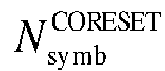
Frequency offset (RBs) 0 1 48 1 0 1 1 48 1 4 2 1 48 1 8 3 1 48 2 0 4 1 48 2 4 5 1 48 2 8 6 1 48 3 0 7 1 48 3 4 8 1 48 3 8 9 1 96 1 18 10 1 96 1 28 11 1 96 1 38 12 1 96 2 18 13 1 96 2 28 14 1 96 2 38 15 Reserved Table 16 (TS 38.213 Table 13-4): RBs set for type 0-PDCCH search space and slot symbols of CORESET when {SS/PBCH block, PDCCH} subcarrier spacing is {30, 30} kHz. Index SS/PBCH Block and CORESET Multiplexing Mode RBs number 
Number of symbols 
Frequency offset (RBs) 0 1 24 2 0 1 1 24 2 1 2 1 24 2 2 3 1 24 2 3 4 1 24 2 4 5 1 24 3 0 6 1 24 3 1 7 1 24 3 2 8 1 24 3 3 9 1 24 3 4 10 1 48 1 10 11 1 48 1 14 12 1 48 1 18 13 1 48 2 10 14 1 48 2 14 15 1 48 2 18 - In summary, some embodiments of the present disclosure provide a systematic system information configuration method for designing all RMSI CORESET configurations based on a rule of minimizing all possible quantities of candidate frequency offset positions within a SS Raster interval, and a rule of aligning the SSB with the RMSI CORESET center, given a combination of carrier frequency bands, channel bandwidths, SSB SCS, and RMSI SCS. The method according to the embodiment of the present invention is used to modify and redesign the existing configuration method in the 3GPP protocol standard, thereby ensuring the correctness of the protocol configuration method.
- In some embodiments of the present disclosure, as shown in
FIG. 6 , a system information configuration device is also provided in an embodiment of the present disclosure, including: - a first determining
module 601, configured to determine, based on a target parameter which is predetermined, a frequency offset configuration parameter of a Remaining Minimum System Information (RMSI) Control Resource Set (CORESET) with respect to a System Synchronization Block (SSB), where the target parameter includes one or more of a channel bandwidth parameter, a Subcarrier Spacing (SCS) parameter of RMSI, an SCS parameter of SSB, a System Synchronization (SS) Raster parameter, and a RMSI CORESET bandwidth parameter; - a
configuring module 602, configured to perform a frequency offset configuration of the RMSI CORESET with respect to the SSB according to the frequency offset configuration parameter. - According to the system information configuration device in some embodiments of the present disclosure, the frequency offset configuration of the RMSI CORESET with respect to the SSB is performed by combining factors such as the combination of the RMSI SCS and the SSB SCS, the channel bandwidth, the SS Raster, and the RMSI CORESET bandwidth. In consideration of the above, the protocol configuration method is improved, and correctness of the protocol configuration is ensured.
- Optionally, the first determining
module 601 includes:
a first determining submodule, configured to determine, based on the target parameters corresponding to carrier frequency bands in different frequency ranges, the frequency offset configuration parameters of the carrier frequency bands in different frequency ranges; - The
configuration module 602 includes:
a first configuring submodule, configured to perform the frequency offset configuration of the RMSI CORESET with respect to the SSB for the carrier frequency bands in different frequency ranges based on the frequency offset configuration parameters of the carrier frequency bands in different frequency ranges, to obtain frequency offset configuration tables corresponding to the carrier frequency bands in different frequency ranges. - Optionally, the first determining submodule comprises:
a first determining unit, configured to determine the frequency offset configuration parameters of the carrier frequency bands in different frequency ranges, based on the target parameters corresponding to the carrier frequency bands in different frequency ranges under conditions of SS Raster definitions in different carrier frequency bands, different combinations of RMSI SCS and SSB SCS and different minimum channel bandwidths. - Optionally, the carrier frequency bands in different frequency ranges include a carrier frequency band in a frequency range of 0 to 2.65GHz and/or a carrier frequency band in a frequency range of 2.4 GHz to 6GHz;
a minimum channel bandwidth of the carrier frequency band in the frequency range of 0 to 2.65GHz includes 5 MHz, 10 MHz and/or 20 MHz;
a minimum channel bandwidth of the carrier frequency band in the frequency range of 2.4 GHz to 6GHz includes 10 MHz, 20 MHz, and/or 40MHz. - Optionally, the minimum channel bandwidth of the carrier frequency band in the frequency range of 0 to 2.65GHz includes 5 MHz and 10 MHz, and the same frequency offset configuration table at the minimum channel bandwidths of 5 MHz and 10 MHz is used for the carrier frequency bands in the frequency range of 0 to 2.65GHz.
- Optionally, the frequency offset configuration parameter includes a candidate frequency offset quantity and a frequency offset.
- The first determining
module 601 includes:
a second determining submodule configured to determine the candidate frequency offset quantity and the frequency offset based on the target parameter which is predetermined and a predetermined rule, where the predetermined rule includes one or more of a rule of minimizing all possible quantities of candidate frequency offset positions within one SS Raster interval and a rule of aligning the SSB with a center of the RMSI CORESET. - Optionally, the channel bandwidth parameter includes a quantity of Resource Blocks (RBs) within a channel bandwidth, the RMSI CORESET bandwidth parameter includes a quantity of RBs within a RMSI CORESET bandwidth, and the SS Raster parameter includes an SS Raster interval.
- The second determining submodule includes:
- a second determining unit, configured to determine, based on the quantity of RBs within the channel bandwidth and the quantity of RBs within the RMSI CORESET bandwidth, a maximum quantity of positions of the SSB supportable by each offset value in a configuration;
- a third determining unit, configured to determine, based on the SS Raster interval and a maximum quantity of RB positions possible for placing SS Rasters in the channel bandwidth and according to the rule of minimizing all possible quantities of candidate frequency offset positions within one SS Raster interval, a maximum quantity of candidate RB positions possible for placing the SS Rasters in the channel bandwidth;
- a fourth determining unit, configured to determine the candidate frequency offset quantity, based on the maximum quantity of RB positions possible for placing SS Rasters in the channel bandwidth and the maximum quantity of positions of the SSB supportable by each offset value in the configuration;
- a fifth determining unit, configured to determine a candidate set of frequency offsets, based on the candidate frequency offset quantity, the maximum quantity of positions of the SSB supportable by each offset value in the configuration and a predefined initial offset.
- Optionally, the second determining unit includes:
a first determining subunit, configured to determine the maximum quantity of positions Δ SSB of the SSB supportable by each offset value in the configuration, based on the quantity NBW of RBs in a granularity of RMSI RB within the channel bandwidth and the quantity NRMSI of RBs in a granularity of RMSI RB within the RMSI CORESET bandwidth and through the following formula:
where µ is a scaling factor between the SCS of the SSB and the SCS of the RMSI, and floor represents a rounding down function - Optionally, the third determining unit includes:
- a second determining subunit, configured to determine the maximum quantity N' of RB positions possible for placing the SS Rasters in the channel bandwidth, based on the quantity NSSB of RBs in a granularity of SSB RB within the channel bandwidth and through the following formula:

- a third determining subunit configured to determine the maximum quantity N of candidate RB positions possible for placing the SS Rasters in the channel bandwidth, based on the SS Raster interval NSync in a granularity of SSB RB and N' and through the following formula:

where min represents a minimum value finding function. - Optionally, the fourth determining unit includes:
a fourth determining subunit configured to determine the candidate frequency offset quantity P, based on the maximum quantity N of RB positions possible for placing SS Rasters in the channel bandwidth and the maximum quantity of positions Δ SSB of the SSB supportable by each offset value in the configuration and through the following formula:
where ceiling represents an rounding up function. - Optionally, the fifth determining unit includes:
- a fifth determining subunit configured to determine a frequency offset step size Δ RMSI based on the maximum quantity of positions Δ SSB of the SSB supportable by each offset value in the configuration and through the following formula:

where µ is a scaling factor between the SCS of the SSB and the SCS of the RMSI; NRMSI is the quantity of RBs in a granularity of RMSI RB in the RMSI CORESET bandwidth; - a sixth determining subunit configured to determine a value of an ith frequency offset Oi in the candidate set of frequency offsets, based on the candidate frequency offset quantity P, the frequency offset step size Δ RMSI and the predefined initial offset O 0 and through the following formula:

where 1≤i≤P. - Optionally, the device further includes:
a second determining module, configured to determine the initial offset O 0, based on the quantity NRMSI of RBs in the granularity of RMSI RB in the RMSI CORESET bandwidth, the candidate frequency offset quantity P and the frequency offset step size Δ RMSI and the rule of aligning the SSB with the center of the RMSI CORESET. - Optionally, the second determining module includes:
a third determining submodule, configured to determine the initial offset O 0, based on the quantity NRMSI of RBs in the granularity of RMSI RB in the RMSI CORESET bandwidth, the candidate frequency offset quantity P and the frequency offset step size Δ RMSI and the rule of aligning the SSB with the center of the RMSI CORESET and through the following formula:
- According to the system information configuration device in some embodiments of the present disclosure, the frequency offset configuration of the RMSI CORESET with respect to the SSB is performed by combining factors such as the combination of the RMSI SCS and the SSB SCS, the channel bandwidth, the SS Raster, and the RMSI CORESET bandwidth. In consideration of the above, the protocol configuration method is improved, and correctness of the protocol configuration is ensured.
- It should be noted that all the implementations of the system information configuration method described above are applicable to the embodiments of the system information configuration device, and the same technical effect can be achieved.
- In some embodiments of the present disclosure, as shown in
FIG. 7 , a system information configuration device is further provided, including atransceiver 710, amemory 720, aprocessor 700, a bus interface, and a computer program stored in thememory 720 and executable on theprocessor 700; - The
processor 700 is configured to read a program in a memory to determine, based on a target parameter which is predetermined, a frequency offset configuration parameter of a Remaining Minimum System Information (RMSI) Control Resource Set (CORESET) with respect to a System Synchronization Block (SSB), where the target parameter includes one or more of a channel bandwidth parameter, a Subcarrier Spacing (SCS) parameter of RMSI, an SCS parameter of SSB, a System Synchronization (SS) Raster parameter, and a RMSI CORESET bandwidth parameter; and perform a frequency offset configuration of the RMSI CORESET with respect to the SSB according to the frequency offset configuration parameter. - According to the system information configuration device of some embodiments of the present disclosure, the frequency offset configuration of the RMSI CORESET with respect to the SSB is performed by combining factors such as the combination of the RMSI SCS and the SSB SCS, the channel bandwidth, the SS Raster, and the RMSI CORESET bandwidth. In consideration of the above, the protocol configuration method is improved, and correctness of the protocol configuration is ensured.
- In
FIG. 7 , the bus architecture may include any number of interconnected buses and bridges, specifically, the various circuits of one or more processors represented by theprocessor 700 and the memory represented by thememory 720 are linked together. The bus architecture may also link various other circuits, such as peripherals, voltage regulators, and power management circuits, all of which are well known in the art and therefore will not be described further herein. The bus interface provides an interface.Transceiver 710 may be a plurality of elements, including a transmitter and a transceiver, providing units for communicating with various other devices on a transmission medium. Theprocessor 700 is responsible for managing the bus architecture and general processing, and thememory 720 may store data used by theprocessor 700 in performing operations. - Optionally, the
processor 700 is configured to read the program in the memory to: - determine, based on the target parameters corresponding to carrier frequency bands in different frequency ranges, the frequency offset configuration parameters of the carrier frequency bands in different frequency ranges;
- perform the frequency offset configuration of the RMSI CORESET with respect to the SSB for the carrier frequency bands in different frequency ranges based on the frequency offset configuration parameters of the carrier frequency bands in different frequency ranges, to obtain frequency offset configuration tables corresponding to the carrier frequency bands in different frequency ranges.
- Optionally, the
processor 700 is configured to read the program in the memory to:
determine the frequency offset configuration parameters of the carrier frequency bands in different frequency ranges, based on the target parameters corresponding to the carrier frequency bands in different frequency ranges under conditions of SS Raster definitions in different carrier frequency bands, different combinations of RMSI SCS and SSB SCS and different minimum channel bandwidths. - Optionally, the carrier frequency bands in different frequency ranges include a carrier frequency band in a frequency range of 0 to 2.65GHz and/or a carrier frequency band in a frequency range of 2.4 GHz to 6GHz;
a minimum channel bandwidth of the carrier frequency band in the frequency range of 0 to 2.65GHz includes 5 MHz, 10 MHz and/or 20 MHz;
a minimum channel bandwidth of the carrier frequency band in the frequency range of 2.4 GHz to 6GHz includes 10 MHz, 20 MHz, and/or 40MHz. - Optionally, the minimum channel bandwidth of the carrier frequency band in the frequency range of 0 to 2.65GHz includes 5 MHz and 10 MHz, and the same frequency offset configuration table at the minimum channel bandwidths of 5 MHz and 10 MHz is used for the carrier frequency bands in the frequency range of 0 to 2.65GHz.
- Optionally, the frequency offset configuration parameter includes a candidate frequency offset quantity and a frequency offset;
theprocessor 700 is configured to read the program in the memory to: - determine the candidate frequency offset quantity and the frequency offset based on the target parameter which is predetermined and a predetermined rule;
- where the predetermined rule includes one or more of a rule of minimizing all possible quantities of candidate frequency offset positions within one SS Raster interval and a rule of aligning the SSB with a center of the RMSI CORESET.
- Optionally, the channel bandwidth parameter includes a quantity of Resource Blocks (RBs) within a channel bandwidth, the RMSI CORESET bandwidth parameter includes a quantity of RBs within a RMSI CORESET bandwidth, and the SS Raster parameter includes an SS Raster interval;
theprocessor 700 is configured to read the program in the memory to: - determine, based on the quantity of RBs within the channel bandwidth and the quantity of RBs within the RMSI CORESET bandwidth, a maximum quantity of positions of the SSB supportable by each offset value in a configuration;
- determine, based on the SS Raster interval and a maximum quantity of RB positions possible for placing SS Rasters in the channel bandwidth and according to the rule of minimizing all possible quantities of candidate frequency offset positions within one SS Raster interval, a maximum quantity of candidate RB positions possible for placing the SS Rasters in the channel bandwidth;
- determine the candidate frequency offset quantity, based on the maximum quantity of RB positions possible for placing SS Rasters in the channel bandwidth and the maximum quantity of positions of the SSB supportable by each offset value in the configuration; and
- determine a candidate set of frequency offsets, based on the candidate frequency offset quantity, the maximum quantity of positions of the SSB supportable by each offset value in the configuration and a predefined initial offset.
- Optionally, the
processor 700 is configured to read the program in the memory to:
determine the maximum quantity of positions Δ SSB of the SSB supportable by each offset value in the configuration, based on the quantity NBW of RBs in a granularity of RMSI RB within the channel bandwidth and the quantity NRMSI of RBs in a granularity of RMSI RB within the RMSI CORESET bandwidth and through the following formula:
where µ is a scaling factor between the SCS of the SSB and the SCS of the RMSI, and floor represents a rounding down function. - Optionally, the
processor 700 is configured to read the program in the memory to:
determine the maximum quantity N' of RB positions possible for placing the SS Rasters in the channel bandwidth, based on the quantity NSSB of RBs in a granularity of SSB RB within the channel bandwidth and through the following formula:
determine the maximum quantity N of candidate RB positions possible for placing the SS Rasters in the channel bandwidth, based on the SS Raster interval NSync in a granularity of SSB RB and N' and through the following formula:
where min represents a minimum value finding function. - Optionally, the
processor 700 is configured to read the program in the memory to:
determine the candidate frequency offset quantity P, based on the maximum quantity N of RB positions possible for placing SS Rasters in the channel bandwidth and the maximum quantity of positions Δ SSB of the SSB supportable by each offset value in the configuration and through the following formula:
where ceiling represents an rounding up function. - Optionally, the
processor 700 is configured to read the program in the memory to:
determine a frequency offset step size Δ RMSI based on the maximum quantity of positions Δ SSB of the SSB supportable by each offset value in the configuration and through the following formula:
where µ is a scaling factor between the SCS of the SSB and the SCS of the RMSI; NRMSI is the quantity of RBs in a granularity of RMSI RB in the RMSI CORESET bandwidth;
determine a value of an ith frequency offset Oi in the candidate set of frequency offsets, based on the candidate frequency offset quantity P, the frequency offset step size Δ RMSI and the predefined initial offset O 0 and through the following formula:
where 1≤i≤P. - Optionally, the
processor 700 is configured to read the program in the memory to:
determine the initial offset O 0, based on the quantity NRMSI of RBs in the granularity of RMSI RB in the RMSI CORESET bandwidth, the candidate frequency offset quantity P and the frequency offset step size Δ RMSI and the rule of aligning the SSB with the center of the RMSI CORESET. - Optionally, the
processor 700 is configured to read the program in the memory to:
determine the initial offset O 0, based on the quantity NRMSI of RBs in the granularity of RMSI RB in the RMSI CORESET bandwidth, the candidate frequency offset quantity P and the frequency offset step size Δ RMSI and the rule of aligning the SSB with the center of the RMSI CORESET and through the following formula:
- In some embodiments of the present disclosure, a computer readable storage medium storing a computer program is further provided, the computer program is executed by a processor to:
- determine, based on a target parameter which is predetermined, a frequency offset configuration parameter of a Remaining Minimum System Information (RMSI) Control Resource Set (CORESET) with respect to a System Synchronization Block (SSB), where the target parameter includes one or more of a channel bandwidth parameter, a Subcarrier Spacing (SCS) parameter of RMSI, an SCS parameter of SSB, a System Synchronization (SS) Raster parameter, and a RMSI CORESET bandwidth parameter; and
- perform a frequency offset configuration of the RMSI CORESET with respect to the SSB according to the frequency offset configuration parameter.
- Optionally, the processor is configured to read the program in the memory to:
- determine, based on the target parameters corresponding to carrier frequency bands in different frequency ranges, the frequency offset configuration parameters of the carrier frequency bands in different frequency ranges;
- perform the frequency offset configuration of the RMSI CORESET with respect to the SSB for the carrier frequency bands in different frequency ranges based on the frequency offset configuration parameters of the carrier frequency bands in different frequency ranges, to obtain frequency offset configuration tables corresponding to the carrier frequency bands in different frequency ranges.
- Optionally, the processor is configured to read the program in the memory to:
determine the frequency offset configuration parameters of the carrier frequency bands in different frequency ranges, based on the target parameters corresponding to the carrier frequency bands in different frequency ranges under conditions of SS Raster definitions in different carrier frequency bands, different combinations of RMSI SCS and SSB SCS and different minimum channel bandwidths. - Optionally, the carrier frequency bands in different frequency ranges include a carrier frequency band in a frequency range of 0 to 2.65GHz and/or a carrier frequency band in a frequency range of 2.4 GHz to 6GHz;
a minimum channel bandwidth of the carrier frequency band in the frequency range of 0 to 2.65GHz includes 5 MHz, 10 MHz and/or 20 MHz;
a minimum channel bandwidth of the carrier frequency band in the frequency range of 2.4 GHz to 6GHz includes 10 MHz, 20 MHz, and/or 40MHz. - Optionally, the minimum channel bandwidth of the carrier frequency band in the frequency range of 0 to 2.65GHz includes 5 MHz and 10 MHz, and the same frequency offset configuration table at the minimum channel bandwidths of 5 MHz and 10 MHz is used for the carrier frequency bands in the frequency range of 0 to 2.65GHz.
- Optionally, the frequency offset configuration parameter includes a candidate frequency offset quantity and a frequency offset;
the processor is configured to read the program in the memory to:
determine the candidate frequency offset quantity and the frequency offset based on the target parameter which is predetermined and a predetermined rule;
where the predetermined rule includes one or more of a rule of minimizing all possible quantities of candidate frequency offset positions within one SS Raster interval and a rule of aligning the SSB with a center of the RMSI CORESET. - Optionally, the channel bandwidth parameter includes a quantity of Resource Blocks (RBs) within a channel bandwidth, the RMSI CORESET bandwidth parameter includes a quantity of RBs within a RMSI CORESET bandwidth, and the SS Raster parameter includes an SS Raster interval;
the processor is configured to read the program in the memory to: - determine, based on the quantity of RBs within the channel bandwidth and the quantity of RBs within the RMSI CORESET bandwidth, a maximum quantity of positions of the SSB supportable by each offset value in a configuration;
- determine, based on the SS Raster interval and a maximum quantity of RB positions possible for placing SS Rasters in the channel bandwidth and according to the rule of minimizing all possible quantities of candidate frequency offset positions within one SS Raster interval, a maximum quantity of candidate RB positions possible for placing the SS Rasters in the channel bandwidth;
- determine the candidate frequency offset quantity, based on the maximum quantity of RB positions possible for placing SS Rasters in the channel bandwidth and the maximum quantity of positions of the SSB supportable by each offset value in the configuration; and
- determine a candidate set of frequency offsets, based on the candidate frequency offset quantity, the maximum quantity of positions of the SSB supportable by each offset value in the configuration and a predefined initial offset.
- Optionally, the processor is configured to read the program in the memory to:
determine the maximum quantity of positions Δ SSB of the SSB supportable by each offset value in the configuration, based on the quantity NBW of RBs in a granularity of RMSI RB within the channel bandwidth and the quantity NRMSI of RBs in a granularity of RMSI RB within the RMSI CORESET bandwidth and through the following formula:
where µ is a scaling factor between the SCS of the SSB and the SCS of the RMSI, and floor represents a rounding down function. - Optionally, the processor is configured to read the program in the memory to:
determine the maximum quantity N' of RB positions possible for placing the SS Rasters in the channel bandwidth, based on the quantity NSSB of RBs in a granularity of SSB RB within the channel bandwidth and through the following formula:
determine the maximum quantity N of candidate RB positions possible for placing the SS Rasters in the channel bandwidth, based on the SS Raster interval NSync in a granularity of SSB RB and N' and through the following formula:
where min represents a minimum value finding function. - Optionally, the processor is configured to read the program in the memory to:
determine the candidate frequency offset quantity P, based on the maximum quantity N of RB positions possible for placing SS Rasters in the channel bandwidth and the maximum quantity of positions ΔSSB of the SSB supportable by each offset value in the configuration and through the following formula:
where ceiling represents an rounding up function. - Optionally, the processor is configured to read the program in the memory to:
determine a frequency offset step size Δ RMSI based on the maximum quantity of positions Δ SSB of the SSB supportable by each offset value in the configuration and through the following formula:
where µ is a scaling factor between the SCS of the SSB and the SCS of the RMSI; NRMSI is the quantity of RBs in a granularity of RMSI RB in the RMSI CORESET bandwidth;
determine a value of an ith frequency offset Oi in the candidate set of frequency offsets, based on the candidate frequency offset quantity P, the frequency offset step size Δ RMSI and the predefined initial offset O 0 and through the following formula:
where 1≤i≤P. - Optionally, the processor is configured to read the program in the memory to:
determine the initial offset O 0, based on the quantity NRMSI of RBs in the granularity of RMSI RB in the RMSI CORESET bandwidth, the candidate frequency offset quantity P and the frequency offset step size Δ RMSI and the rule of aligning the SSB with the center of the RMSI CORESET. - Optionally, the processor is configured to read the program in the memory to:
determine the initial offset O 0, based on the quantity NRMSI of RBs in the granularity of RMSI RB in the RMSI CORESET bandwidth, the candidate frequency offset quantity P and the frequency offset step size Δ RMSI and the rule of aligning the SSB with the center of the RMSI CORESET and through the following formula:
- In the various embodiments of the present disclosure, it is to be understood that the magnitude of the sequence numbers of the processes described above is not intended to mean the order of execution, and that the order of execution of the processes should be determined by their function and intrinsic logic, and should not constitute any limitation on the implementation of some embodiments of the present disclosure.
- Some embodiments of the present disclosure have been described above, it should be noted that several modifications and embellishments may be made by those of ordinary skill in the art without departing from the principles set forth in the present disclosure, and such modifications and embellishments are also considered to be within the scope of the present disclosure.
Claims (28)
- A system information configuration method, comprising:determining, based on a target parameter which is predetermined, a frequency offset configuration parameter of a Remaining Minimum System Information (RMSI) Control Resource Set (CORESET) with respect to a System Synchronization Block (SSB), wherein the target parameter comprises one or more of a channel bandwidth parameter, a Subcarrier Spacing (SCS) parameter of RMSI, an SCS parameter of SSB, a System Synchronization (SS) Raster parameter, and a RMSI CORESET bandwidth parameter; andperforming a frequency offset configuration of the RMSI CORESET with respect to the SSB according to the frequency offset configuration parameter.
- The method according to claim 1, wherein the determining based on the target parameter which is predetermined the frequency offset configuration parameter of the RMSI CORESET with respect to the SSB comprises:determining, based on the target parameters corresponding to carrier frequency bands in different frequency ranges, the frequency offset configuration parameters of the carrier frequency bands in different frequency ranges;performing the frequency offset configuration of the RMSI CORESET with respect to the SSB according to the frequency offset configuration parameter comprises:
performing the frequency offset configuration of the RMSI CORESET with respect to the SSB for the carrier frequency bands in different frequency ranges based on the frequency offset configuration parameters of the carrier frequency bands in different frequency ranges, to obtain frequency offset configuration tables corresponding to the carrier frequency bands in different frequency ranges. - The method according to claim 2, wherein the determining based on the target parameters corresponding to the carrier frequency bands in different frequency ranges the frequency offset configuration parameters of the carrier frequency bands in different frequency ranges comprises:
determining the frequency offset configuration parameters of the carrier frequency bands in different frequency ranges, based on the target parameters corresponding to the carrier frequency bands in different frequency ranges under conditions of SS Raster definitions in different carrier frequency bands, different combinations of RMSI SCS and SSB SCS and different minimum channel bandwidths. - The method according to claim 3, wherein the carrier frequency bands in different frequency ranges comprise a carrier frequency band in the frequency range of 0 to 2.65GHz and/or a carrier frequency band in the frequency range of 2.4 GHz to 6GHz;
a minimum channel bandwidth of the carrier frequency band in the frequency range of 0 to 2.65GHz comprises 5 MHz, 10 MHz and/or 20 MHz;
a minimum channel bandwidth of the carrier frequency band in the frequency range of 2.4 GHz to 6GHz comprises 10 MHz, 20 MHz, and/or 40MHz. - The method according to claim 4, wherein the minimum channel bandwidth of the carrier frequency band in the frequency range of 0 to 2.65GHz comprises 5 MHz and 10 MHz, and the same frequency offset configuration table at the minimum channel bandwidths of 5 MHz and 10 MHz is used for the carrier frequency bands in the frequency range of 0 to 2.65GHz.
- The method according to claim 1, wherein the frequency offset configuration parameter comprises a candidate frequency offset quantity and a frequency offset;
the determining, based on the target parameter which is predetermined, the frequency offset configuration parameter of the RMSI CORESET with respect to the SSB comprises:determining the candidate frequency offset quantity and the frequency offset based on the target parameter which is predetermined and a predetermined rule;wherein the predetermined rule comprises one or more of a rule of minimizing all possible quantities of candidate frequency offset positions within one SS Raster interval and a rule of aligning the SSB with a center of the RMSI CORESET. - The method according to claim 6, wherein the channel bandwidth parameter comprises a quantity of Resource Blocks (RBs) within a channel bandwidth, the RMSI CORESET bandwidth parameter comprises a quantity of RBs within a RMSI CORESET bandwidth, and the SS Raster parameter comprises an SS Raster interval;
the determining the candidate frequency offset quantity and the frequency offset based on the target parameter which is predetermined and the predetermined rule comprises:determining, based on the quantity of RBs within the channel bandwidth and the quantity of RBs within the RMSI CORESET bandwidth, a maximum quantity of positions of the SSB supportable by each offset value in a configuration;determining, based on the SS Raster interval and a maximum quantity of RB positions possible for placing SS Rasters in the channel bandwidth and according to the rule of minimizing all possible quantities of candidate frequency offset positions within one SS Raster interval, a maximum quantity of candidate RB positions possible for placing the SS Rasters in the channel bandwidth;determining the candidate frequency offset quantity, based on the maximum quantity of RB positions possible for placing SS Rasters in the channel bandwidth and the maximum quantity of positions of the SSB supportable by each offset value in the configuration; anddetermining a candidate set of frequency offsets, based on the candidate frequency offset quantity, the maximum quantity of positions of the SSB supportable by each offset value in the configuration and a predefined initial offset. - The method according to claim 7, wherein the determining, based on the quantity of RBs within the channel bandwidth and the quantity of RBs within the RMSI CORESET bandwidth, the maximum quantity of positions of the SSB supportable by each offset value in the configuration comprises:
determining the maximum quantity of positions Δ SSB of the SSB supportable by each offset value in the configuration, based on the quantity NBW of RBs in a granularity of RMSI RB within the channel bandwidth and the quantity NRMSI of RBs in a granularity of RMSI RB within the RMSI CORESET bandwidth and through the following formula:
- The method according to claim 7, wherein the determining, based on the SS Raster interval and the maximum quantity of RB positions possible for placing SS Rasters in the channel bandwidth and according to the rule of minimizing all possible quantities of candidate frequency offset positions within one SS Raster interval, the maximum quantity of candidate RB positions possible for placing the SS Rasters in the channel bandwidth comprises:
determining the maximum quantity N' of RB positions possible for placing the SS Rasters in the channel bandwidth, based on the quantity NSSB of RBs in a granularity of SSB RB within the channel bandwidth and through the following formula:

- The method according to claim 7, wherein the determining the candidate frequency offset quantity, based on the maximum quantity of RB positions possible for placing SS Rasters in the channel bandwidth and the maximum quantity of positions of the SSB supportable by each offset value in the configuration comprises:
determining the candidate frequency offset quantity P, based on the maximum quantity N of RB positions possible for placing SS Rasters in the channel bandwidth and the maximum quantity of positions Δ SSB of the SSB supportable by each offset value in the configuration and through the following formula:
- The method according to claim 7, wherein the determining the candidate set of frequency offsets, based on the candidate frequency offset quantity, the maximum quantity of positions of the SSB supportable by each offset value in the configuration and the predefined initial offset comprises:
determining a frequency offset step size Δ RMSI based on the maximum quantity of positions Δ SSB of the SSB supportable by each offset value in the configuration and through the following formula:
determining a value of an ith frequency offset Oi in the candidate set of frequency offsets, based on the candidate frequency offset quantity P, the frequency offset step size Δ RMSI and the predefined initial offset O 0 and through the following formula:
- The method according to claim 11, wherein prior to the determining the value of the ith frequency offset Oi in the candidate set of frequency offsets, based on the candidate frequency offset quantity P, the frequency offset step size Δ RMSI and the predefined initial offset O 0, the method further comprises:
determining the initial offset O 0, based on the quantity NRMSI of RBs in the granularity of RMSI RB in the RMSI CORESET bandwidth, the candidate frequency offset quantity P and the frequency offset step size Δ RMSI and the rule of aligning the SSB with the center of the RMSI CORESET. - The method according to claim 12, wherein the determining the initial offset O 0, based on the quantity NRMSI of RBs in the granularity of RMSI RB in the RMSI CORESET bandwidth, the candidate frequency offset quantity P and the frequency offset step size Δ RMSI and the rule of aligning the SSB with the center of the RMSI CORESET comprises:
determining the initial offset O 0, based on the quantity NRMSI of RBs in the granularity of RMSI RB in the RMSI CORESET bandwidth, the candidate frequency offset quantity P and the frequency offset step size Δ RMSI and the rule of aligning the SSB with the center of the RMSI CORESET and through the following formula:
- A system information configuration device, comprising:a determining module, configured to determine, based on a target parameter which is predetermined, a frequency offset configuration parameter of a Remaining Minimum System Information (RMSI) Control Resource Set (CORESET) with respect to a System Synchronization Block (SSB), wherein the target parameter comprises one or more of a channel bandwidth parameter, a Subcarrier Spacing (SCS) parameter of RMSI, an SCS parameter of SSB, a System Synchronization (SS) Raster parameter, and a RMSI CORESET bandwidth parameter; anda configuring module, configured to perform a frequency offset configuration of the RMSI CORESET with respect to the SSB according to the frequency offset configuration parameter.
- A system information configuration device, comprising a transceiver, a memory, a processor and a computer program stored in the memory and executable on the processor;
the processor is configured to read a program in the memory to:determine, based on a target parameter which is predetermined, a frequency offset configuration parameter of a Remaining Minimum System Information (RMSI) Control Resource Set (CORESET) with respect to a System Synchronization Block (SSB), wherein the target parameter comprises one or more of a channel bandwidth parameter, a Subcarrier Spacing (SCS) parameter of RMSI, an SCS parameter of SSB, a System Synchronization (SS) Raster parameter, and a RMSI CORESET bandwidth parameter; andperform a frequency offset configuration of the RMSI CORESET with respect to the SSB according to the frequency offset configuration parameter. - The device according to claim 15, wherein the processor is configured to read the program in the memory to:determine, based on the target parameters corresponding to carrier frequency bands in different frequency ranges, the frequency offset configuration parameters of the carrier frequency bands in different frequency ranges;perform the frequency offset configuration of the RMSI CORESET with respect to the SSB for the carrier frequency bands in different frequency ranges based on the frequency offset configuration parameters of the carrier frequency bands in different frequency ranges, to obtain frequency offset configuration tables corresponding to the carrier frequency bands in different frequency ranges.
- The device according to claim 15, wherein the processor is configured to read the program in the memory to:
determine the frequency offset configuration parameters of the carrier frequency bands in different frequency ranges, based on the target parameters corresponding to the carrier frequency bands in different frequency ranges under conditions of SS Raster definitions in different carrier frequency bands, different combinations of RMSI SCS and SSB SCS and different minimum channel bandwidths. - The device according to claim 17, wherein the carrier frequency bands in different frequency ranges comprise a carrier frequency band in the frequency range of 0 to 2.65GHz and/or a carrier frequency band in the frequency range of 2.4 GHz to 6GHz;
a minimum channel bandwidth of the carrier frequency band in the frequency range of 0 to 2.65GHz comprises 5 MHz, 10 MHz and/or 20 MHz;
a minimum channel bandwidth of the carrier frequency band in the frequency range of 2.4 GHz to 6GHz comprises 10 MHz, 20 MHz, and/or 40MHz. - The device according to claim 18, wherein the minimum channel bandwidth of the carrier frequency band in the frequency range of 0 to 2.65GHz comprises 5 MHz and 10 MHz, and the same frequency offset configuration table at the minimum channel bandwidths of 5 MHz and 10 MHz is used for the carrier frequency bands in the frequency range of 0 to 2.65GHz.
- The device according to claim 15, wherein the frequency offset configuration parameter comprises a candidate frequency offset quantity and a frequency offset;
the processor is configured to read the program in the memory to:determine the candidate frequency offset quantity and the frequency offset based on the target parameter which is predetermined and a predetermined rule;wherein the predetermined rule comprises one or more of a rule of minimizing all possible quantities of candidate frequency offset positions within one SS Raster interval and a rule of aligning the SSB with a center of the RMSI CORESET. - The device according to claim 20, wherein the channel bandwidth parameter comprises a quantity of Resource Blocks (RBs) within a channel bandwidth, the RMSI CORESET bandwidth parameter comprises a quantity of RBs within a RMSI CORESET bandwidth, and the SS Raster parameter comprises an SS Raster interval;
the processor is configured to read the program in the memory to:determine, based on the quantity of RBs within the channel bandwidth and the quantity of RBs within the RMSI CORESET bandwidth, a maximum quantity of positions of the SSB supportable by each offset value in a configuration;determine, based on the SS Raster interval and a maximum quantity of RB positions possible for placing SS Rasters in the channel bandwidth and according to the rule of minimizing all possible quantities of candidate frequency offset positions within one SS Raster interval, a maximum quantity of candidate RB positions possible for placing the SS Rasters in the channel bandwidth;determine the candidate frequency offset quantity, based on the maximum quantity of RB positions possible for placing SS Rasters in the channel bandwidth and the maximum quantity of positions of the SSB supportable by each offset value in the configuration; anddetermine a candidate set of frequency offsets, based on the candidate frequency offset quantity, the maximum quantity of positions of the SSB supportable by each offset value in the configuration and a predefined initial offset. - The device according to claim 21, wherein the processor is configured to read the program in the memory to:
determine the maximum quantity of positions Δ SSB of the SSB supportable by each offset value in the configuration, based on the quantity NBW of RBs in a granularity of RMSI RB within the channel bandwidth and the quantity NRMSI of RBs in a granularity of RMSI RB within the RMSI CORESET bandwidth and through the following formula:
- The device according to claim 21, wherein the processor is configured to read the program in the memory to:
determine the maximum quantity N' of RB positions possible for placing the SS Rasters in the channel bandwidth, based on the quantity NSSB of RBs in a granularity of SSB RB within the channel bandwidth and through the following formula:

- The device according to claim 21, wherein the processor is configured to read the program in the memory to:
determine the candidate frequency offset quantity P, based on the maximum quantity N of RB positions possible for placing SS Rasters in the channel bandwidth and the maximum quantity of positions Δ SSB of the SSB supportable by each offset value in the configuration and through the following formula:
- The device according to claim 21, wherein the processor is configured to read the program in the memory to:
determine a frequency offset step size Δ RMSI based on the maximum quantity of positions Δ SSB of the SSB supportable by each offset value in the configuration and through the following formula:
determine a value of an ith frequency offset Oi in the candidate set of frequency offsets, based on the candidate frequency offset quantity P, the frequency offset step size Δ RMSI and the predefined initial offset O 0 and through the following formula:
- The device according to claim 25, wherein the processor is configured to read the program in the memory to:
determine the initial offset O 0, based on the quantity NRMSI of RBs in the granularity of RMSI RB in the RMSI CORESET bandwidth, the candidate frequency offset quantity P and the frequency offset step size Δ RMSI and the rule of aligning the SSB with the center of the RMSI CORESET. - The device according to claim 26, wherein the processor is configured to read the program in the memory to:
determine the initial offset O 0, based on the quantity NRMSI of RBs in the granularity of RMSI RB in the RMSI CORESET bandwidth, the candidate frequency offset quantity P and the frequency offset step size Δ RMSI and the rule of aligning the SSB with the center of the RMSI CORESET and through the following formula:
- A computer readable storage medium, wherein a computer program is stored in the computer readable storage medium, the computer program is executed by a processor to perform the system information configuration method according to any one of claims 1 to 13.
Applications Claiming Priority (2)
| Application Number | Priority Date | Filing Date | Title |
|---|---|---|---|
| CN201810032494.XA CN110034891B (en) | 2018-01-12 | 2018-01-12 | System information configuration method and device |
| PCT/CN2019/070963 WO2019137389A1 (en) | 2018-01-12 | 2019-01-09 | System information configuration method and device |
Publications (3)
| Publication Number | Publication Date |
|---|---|
| EP3739797A1 true EP3739797A1 (en) | 2020-11-18 |
| EP3739797A4 EP3739797A4 (en) | 2021-03-03 |
| EP3739797B1 EP3739797B1 (en) | 2023-03-01 |
Family
ID=67218507
Family Applications (1)
| Application Number | Title | Priority Date | Filing Date |
|---|---|---|---|
| EP19738542.0A Active EP3739797B1 (en) | 2018-01-12 | 2019-01-09 | System information configuration method and device |
Country Status (6)
| Country | Link |
|---|---|
| US (1) | US11546914B2 (en) |
| EP (1) | EP3739797B1 (en) |
| KR (2) | KR102552443B1 (en) |
| CN (1) | CN110034891B (en) |
| TW (1) | TWI712329B (en) |
| WO (1) | WO2019137389A1 (en) |
Cited By (1)
| Publication number | Priority date | Publication date | Assignee | Title |
|---|---|---|---|---|
| US12408130B2 (en) | 2020-07-31 | 2025-09-02 | Beijing Xiaomi Mobile Software Co., Ltd. | Method and apparatus for determining offset indication, and method and apparatus for determining offset |
Families Citing this family (16)
| Publication number | Priority date | Publication date | Assignee | Title |
|---|---|---|---|---|
| CN111106913B (en) * | 2018-11-02 | 2021-04-27 | 维沃移动通信有限公司 | Method and apparatus for wireless communication |
| US11234219B2 (en) * | 2019-01-11 | 2022-01-25 | Intel Corporation | Discovery reference signal and control resource set multiplexing |
| CN111525995B (en) * | 2019-02-03 | 2022-03-29 | 华为技术有限公司 | Data transmission method, network equipment and terminal equipment |
| CN113316267B (en) * | 2019-03-01 | 2023-01-13 | Oppo广东移动通信有限公司 | Wireless communication method, terminal device and network device |
| WO2021031002A1 (en) * | 2019-08-16 | 2021-02-25 | 华为技术有限公司 | Method and apparatus for indicating control information |
| WO2021062575A1 (en) | 2019-09-30 | 2021-04-08 | 富士通株式会社 | Signal transmission method and apparatus, and communication system |
| KR102737009B1 (en) * | 2019-10-02 | 2024-12-03 | 엘지전자 주식회사 | Method and apparatus for transmitting/receiving wireless signal in wireless communication system |
| CN114503646B (en) * | 2019-10-02 | 2023-10-27 | Lg电子株式会社 | Method and apparatus for transmitting and receiving wireless signals in a wireless communication system |
| US11539486B2 (en) * | 2019-11-05 | 2022-12-27 | Qualcomm Incorporated | SSB enhancements for fine time-frequency estimation in NR |
| CN111010742B (en) * | 2019-12-09 | 2022-07-15 | Oppo广东移动通信有限公司 | Method and terminal device for determining random access resources |
| CN115702589B (en) * | 2020-07-30 | 2024-11-08 | Oppo广东移动通信有限公司 | Method, device, equipment and storage medium for transmitting synchronous signal block |
| CN112218316B (en) * | 2020-10-09 | 2024-08-02 | 广东省新一代通信与网络创新研究院 | Frequency point configuration calculation method, device and storage medium of 5GNR cell |
| WO2022087868A1 (en) * | 2020-10-28 | 2022-05-05 | 北京小米移动软件有限公司 | Information transmission method and apparatus, communication device and storage medium |
| CN114531697A (en) * | 2020-11-23 | 2022-05-24 | 维沃移动通信有限公司 | Transmission processing method and device and communication equipment |
| JP7726447B2 (en) * | 2021-09-30 | 2025-08-20 | 株式会社Nttドコモ | Terminal, base station, communication system, and communication method |
| US20240146457A1 (en) * | 2022-10-28 | 2024-05-02 | Samsung Electronics Co., Ltd. | Method and apparatus for ss/pbch block for narrow channel bandwidth |
Family Cites Families (7)
| Publication number | Priority date | Publication date | Assignee | Title |
|---|---|---|---|---|
| US8868110B2 (en) * | 2011-11-21 | 2014-10-21 | Broadcom Corporation | Wireless communication device capable of efficient network search |
| CN105007631B (en) * | 2015-08-05 | 2018-06-26 | 山东大学 | The federated resource distribution method that guaranteed qos require in a kind of cooperative cognitive network |
| CN107046721B (en) * | 2016-02-05 | 2020-03-03 | 中兴通讯股份有限公司 | Method and device for transmitting information |
| CN108282877B (en) * | 2017-01-06 | 2023-12-01 | 华为技术有限公司 | Reference signal configuration method, device and system |
| US10616877B2 (en) * | 2017-11-16 | 2020-04-07 | Huawei Technologies Co., Ltd. | Configuration of the initial active bandwidth part for initial network access |
| US10993248B2 (en) * | 2017-11-17 | 2021-04-27 | Qualcomm Incorporated | Designs for remaining minimum system information (RMSI) control resource set (CORESET) and other system information (OSI) coreset |
| US11337220B2 (en) * | 2017-11-30 | 2022-05-17 | Beijing Xiaomi Mobile Software Co., Ltd. | Information indication method and apparatus, base station, and user equipment |
-
2018
- 2018-01-12 CN CN201810032494.XA patent/CN110034891B/en active Active
-
2019
- 2019-01-09 KR KR1020227029478A patent/KR102552443B1/en active Active
- 2019-01-09 KR KR1020207021538A patent/KR20200102478A/en not_active Ceased
- 2019-01-09 US US16/961,217 patent/US11546914B2/en active Active
- 2019-01-09 WO PCT/CN2019/070963 patent/WO2019137389A1/en not_active Ceased
- 2019-01-09 EP EP19738542.0A patent/EP3739797B1/en active Active
- 2019-01-11 TW TW108101131A patent/TWI712329B/en active
Cited By (1)
| Publication number | Priority date | Publication date | Assignee | Title |
|---|---|---|---|---|
| US12408130B2 (en) | 2020-07-31 | 2025-09-02 | Beijing Xiaomi Mobile Software Co., Ltd. | Method and apparatus for determining offset indication, and method and apparatus for determining offset |
Also Published As
| Publication number | Publication date |
|---|---|
| KR102552443B1 (en) | 2023-07-05 |
| US11546914B2 (en) | 2023-01-03 |
| TWI712329B (en) | 2020-12-01 |
| KR20200102478A (en) | 2020-08-31 |
| TW201931922A (en) | 2019-08-01 |
| US20210058931A1 (en) | 2021-02-25 |
| EP3739797A4 (en) | 2021-03-03 |
| CN110034891B (en) | 2020-10-20 |
| KR20220122806A (en) | 2022-09-02 |
| EP3739797B1 (en) | 2023-03-01 |
| WO2019137389A1 (en) | 2019-07-18 |
| CN110034891A (en) | 2019-07-19 |
Similar Documents
| Publication | Publication Date | Title |
|---|---|---|
| EP3739797B1 (en) | System information configuration method and device | |
| US10887006B2 (en) | Apparatus, system and method for utilizing a flexible slot format indicator | |
| US12432747B2 (en) | Frequency domain resource assignment method and device | |
| EP4221402B1 (en) | Information sending method and device and information receiving method and device | |
| US11246150B2 (en) | Uplink transmission method and base station | |
| US20210007107A1 (en) | Downlink control information transmission method, device and network equipment | |
| EP2498562B1 (en) | Method and base station for sending uplink scheduling grant control signaling | |
| EP3641454B1 (en) | Communication methods, network device, terminal device, computer readable storage medium and computer program product | |
| EP3404862A1 (en) | Narrowband pbch transmission method and device | |
| EP3627919B1 (en) | Channel resource set indication method, terminal device and network device | |
| EP3716714A1 (en) | Method and device for signal detection | |
| EP3413667B1 (en) | Uplink and downlink transmission resource allocation method and device | |
| EP3687243A1 (en) | Resource block group dividing method and user terminal | |
| WO2021026692A1 (en) | Method and apparatus for sharing channel occupancy time | |
| EP3364591A1 (en) | Tdd system information transmission method and device | |
| US20150009911A1 (en) | Mobile Communication Method, Wireless Base Station and Mobile Station | |
| US12193067B2 (en) | Method and apparatus of determining RA-RNTI and user equipment | |
| WO2016177076A1 (en) | Data transmission method, client device and serving end device | |
| CN109392180B (en) | A random access method, network side device and mobile communication terminal | |
| CN104184569A (en) | Method and device for processing flexible subframe | |
| CN118301768A (en) | A parameter configuration method, device and storage medium | |
| EP3512254A1 (en) | Communication method and apparatus | |
| KR102353214B1 (en) | Method and device for transmitting/receiving control information | |
| US11159299B2 (en) | Method and device for dividing short transmission time interval of special subframe | |
| EP3544216A1 (en) | Information transmission method and device |
Legal Events
| Date | Code | Title | Description |
|---|---|---|---|
| STAA | Information on the status of an ep patent application or granted ep patent |
Free format text: STATUS: THE INTERNATIONAL PUBLICATION HAS BEEN MADE |
|
| PUAI | Public reference made under article 153(3) epc to a published international application that has entered the european phase |
Free format text: ORIGINAL CODE: 0009012 |
|
| STAA | Information on the status of an ep patent application or granted ep patent |
Free format text: STATUS: REQUEST FOR EXAMINATION WAS MADE |
|
| 17P | Request for examination filed |
Effective date: 20200710 |
|
| AK | Designated contracting states |
Kind code of ref document: A1 Designated state(s): AL AT BE BG CH CY CZ DE DK EE ES FI FR GB GR HR HU IE IS IT LI LT LU LV MC MK MT NL NO PL PT RO RS SE SI SK SM TR |
|
| AX | Request for extension of the european patent |
Extension state: BA ME |
|
| A4 | Supplementary search report drawn up and despatched |
Effective date: 20210128 |
|
| RIC1 | Information provided on ipc code assigned before grant |
Ipc: H04L 5/00 20060101AFI20210122BHEP |
|
| DAV | Request for validation of the european patent (deleted) | ||
| DAX | Request for extension of the european patent (deleted) | ||
| RAP1 | Party data changed (applicant data changed or rights of an application transferred) |
Owner name: DATANG MOBILE COMMUNICATIONS EQUIPMENT CO., LTD. |
|
| STAA | Information on the status of an ep patent application or granted ep patent |
Free format text: STATUS: EXAMINATION IS IN PROGRESS |
|
| 17Q | First examination report despatched |
Effective date: 20210920 |
|
| GRAP | Despatch of communication of intention to grant a patent |
Free format text: ORIGINAL CODE: EPIDOSNIGR1 |
|
| STAA | Information on the status of an ep patent application or granted ep patent |
Free format text: STATUS: GRANT OF PATENT IS INTENDED |
|
| INTG | Intention to grant announced |
Effective date: 20220926 |
|
| GRAS | Grant fee paid |
Free format text: ORIGINAL CODE: EPIDOSNIGR3 |
|
| GRAA | (expected) grant |
Free format text: ORIGINAL CODE: 0009210 |
|
| STAA | Information on the status of an ep patent application or granted ep patent |
Free format text: STATUS: THE PATENT HAS BEEN GRANTED |
|
| AK | Designated contracting states |
Kind code of ref document: B1 Designated state(s): AL AT BE BG CH CY CZ DE DK EE ES FI FR GB GR HR HU IE IS IT LI LT LU LV MC MK MT NL NO PL PT RO RS SE SI SK SM TR |
|
| REG | Reference to a national code |
Ref country code: GB Ref legal event code: FG4D |
|
| REG | Reference to a national code |
Ref country code: CH Ref legal event code: EP Ref country code: AT Ref legal event code: REF Ref document number: 1551756 Country of ref document: AT Kind code of ref document: T Effective date: 20230315 |
|
| REG | Reference to a national code |
Ref country code: DE Ref legal event code: R096 Ref document number: 602019025865 Country of ref document: DE |
|
| REG | Reference to a national code |
Ref country code: IE Ref legal event code: FG4D |
|
| REG | Reference to a national code |
Ref country code: LT Ref legal event code: MG9D |
|
| REG | Reference to a national code |
Ref country code: NL Ref legal event code: MP Effective date: 20230301 |
|
| PG25 | Lapsed in a contracting state [announced via postgrant information from national office to epo] |
Ref country code: RS Free format text: LAPSE BECAUSE OF FAILURE TO SUBMIT A TRANSLATION OF THE DESCRIPTION OR TO PAY THE FEE WITHIN THE PRESCRIBED TIME-LIMIT Effective date: 20230301 Ref country code: NO Free format text: LAPSE BECAUSE OF FAILURE TO SUBMIT A TRANSLATION OF THE DESCRIPTION OR TO PAY THE FEE WITHIN THE PRESCRIBED TIME-LIMIT Effective date: 20230601 Ref country code: LV Free format text: LAPSE BECAUSE OF FAILURE TO SUBMIT A TRANSLATION OF THE DESCRIPTION OR TO PAY THE FEE WITHIN THE PRESCRIBED TIME-LIMIT Effective date: 20230301 Ref country code: LT Free format text: LAPSE BECAUSE OF FAILURE TO SUBMIT A TRANSLATION OF THE DESCRIPTION OR TO PAY THE FEE WITHIN THE PRESCRIBED TIME-LIMIT Effective date: 20230301 Ref country code: HR Free format text: LAPSE BECAUSE OF FAILURE TO SUBMIT A TRANSLATION OF THE DESCRIPTION OR TO PAY THE FEE WITHIN THE PRESCRIBED TIME-LIMIT Effective date: 20230301 Ref country code: ES Free format text: LAPSE BECAUSE OF FAILURE TO SUBMIT A TRANSLATION OF THE DESCRIPTION OR TO PAY THE FEE WITHIN THE PRESCRIBED TIME-LIMIT Effective date: 20230301 |
|
| REG | Reference to a national code |
Ref country code: AT Ref legal event code: MK05 Ref document number: 1551756 Country of ref document: AT Kind code of ref document: T Effective date: 20230301 |
|
| PG25 | Lapsed in a contracting state [announced via postgrant information from national office to epo] |
Ref country code: SE Free format text: LAPSE BECAUSE OF FAILURE TO SUBMIT A TRANSLATION OF THE DESCRIPTION OR TO PAY THE FEE WITHIN THE PRESCRIBED TIME-LIMIT Effective date: 20230301 Ref country code: PL Free format text: LAPSE BECAUSE OF FAILURE TO SUBMIT A TRANSLATION OF THE DESCRIPTION OR TO PAY THE FEE WITHIN THE PRESCRIBED TIME-LIMIT Effective date: 20230301 Ref country code: NL Free format text: LAPSE BECAUSE OF FAILURE TO SUBMIT A TRANSLATION OF THE DESCRIPTION OR TO PAY THE FEE WITHIN THE PRESCRIBED TIME-LIMIT Effective date: 20230301 Ref country code: GR Free format text: LAPSE BECAUSE OF FAILURE TO SUBMIT A TRANSLATION OF THE DESCRIPTION OR TO PAY THE FEE WITHIN THE PRESCRIBED TIME-LIMIT Effective date: 20230602 Ref country code: FI Free format text: LAPSE BECAUSE OF FAILURE TO SUBMIT A TRANSLATION OF THE DESCRIPTION OR TO PAY THE FEE WITHIN THE PRESCRIBED TIME-LIMIT Effective date: 20230301 |
|
| PG25 | Lapsed in a contracting state [announced via postgrant information from national office to epo] |
Ref country code: SM Free format text: LAPSE BECAUSE OF FAILURE TO SUBMIT A TRANSLATION OF THE DESCRIPTION OR TO PAY THE FEE WITHIN THE PRESCRIBED TIME-LIMIT Effective date: 20230301 Ref country code: RO Free format text: LAPSE BECAUSE OF FAILURE TO SUBMIT A TRANSLATION OF THE DESCRIPTION OR TO PAY THE FEE WITHIN THE PRESCRIBED TIME-LIMIT Effective date: 20230301 Ref country code: PT Free format text: LAPSE BECAUSE OF FAILURE TO SUBMIT A TRANSLATION OF THE DESCRIPTION OR TO PAY THE FEE WITHIN THE PRESCRIBED TIME-LIMIT Effective date: 20230703 Ref country code: EE Free format text: LAPSE BECAUSE OF FAILURE TO SUBMIT A TRANSLATION OF THE DESCRIPTION OR TO PAY THE FEE WITHIN THE PRESCRIBED TIME-LIMIT Effective date: 20230301 Ref country code: CZ Free format text: LAPSE BECAUSE OF FAILURE TO SUBMIT A TRANSLATION OF THE DESCRIPTION OR TO PAY THE FEE WITHIN THE PRESCRIBED TIME-LIMIT Effective date: 20230301 Ref country code: AT Free format text: LAPSE BECAUSE OF FAILURE TO SUBMIT A TRANSLATION OF THE DESCRIPTION OR TO PAY THE FEE WITHIN THE PRESCRIBED TIME-LIMIT Effective date: 20230301 |
|
| PG25 | Lapsed in a contracting state [announced via postgrant information from national office to epo] |
Ref country code: SK Free format text: LAPSE BECAUSE OF FAILURE TO SUBMIT A TRANSLATION OF THE DESCRIPTION OR TO PAY THE FEE WITHIN THE PRESCRIBED TIME-LIMIT Effective date: 20230301 Ref country code: IS Free format text: LAPSE BECAUSE OF FAILURE TO SUBMIT A TRANSLATION OF THE DESCRIPTION OR TO PAY THE FEE WITHIN THE PRESCRIBED TIME-LIMIT Effective date: 20230701 |
|
| REG | Reference to a national code |
Ref country code: DE Ref legal event code: R097 Ref document number: 602019025865 Country of ref document: DE |
|
| PLBE | No opposition filed within time limit |
Free format text: ORIGINAL CODE: 0009261 |
|
| STAA | Information on the status of an ep patent application or granted ep patent |
Free format text: STATUS: NO OPPOSITION FILED WITHIN TIME LIMIT |
|
| PG25 | Lapsed in a contracting state [announced via postgrant information from national office to epo] |
Ref country code: SI Free format text: LAPSE BECAUSE OF FAILURE TO SUBMIT A TRANSLATION OF THE DESCRIPTION OR TO PAY THE FEE WITHIN THE PRESCRIBED TIME-LIMIT Effective date: 20230301 Ref country code: DK Free format text: LAPSE BECAUSE OF FAILURE TO SUBMIT A TRANSLATION OF THE DESCRIPTION OR TO PAY THE FEE WITHIN THE PRESCRIBED TIME-LIMIT Effective date: 20230301 |
|
| 26N | No opposition filed |
Effective date: 20231204 |
|
| PG25 | Lapsed in a contracting state [announced via postgrant information from national office to epo] |
Ref country code: IT Free format text: LAPSE BECAUSE OF FAILURE TO SUBMIT A TRANSLATION OF THE DESCRIPTION OR TO PAY THE FEE WITHIN THE PRESCRIBED TIME-LIMIT Effective date: 20230301 |
|
| PG25 | Lapsed in a contracting state [announced via postgrant information from national office to epo] |
Ref country code: MC Free format text: LAPSE BECAUSE OF FAILURE TO SUBMIT A TRANSLATION OF THE DESCRIPTION OR TO PAY THE FEE WITHIN THE PRESCRIBED TIME-LIMIT Effective date: 20230301 |
|
| PG25 | Lapsed in a contracting state [announced via postgrant information from national office to epo] |
Ref country code: MC Free format text: LAPSE BECAUSE OF FAILURE TO SUBMIT A TRANSLATION OF THE DESCRIPTION OR TO PAY THE FEE WITHIN THE PRESCRIBED TIME-LIMIT Effective date: 20230301 |
|
| REG | Reference to a national code |
Ref country code: CH Ref legal event code: PL |
|
| PG25 | Lapsed in a contracting state [announced via postgrant information from national office to epo] |
Ref country code: LU Free format text: LAPSE BECAUSE OF NON-PAYMENT OF DUE FEES Effective date: 20240109 |
|
| PG25 | Lapsed in a contracting state [announced via postgrant information from national office to epo] |
Ref country code: LU Free format text: LAPSE BECAUSE OF NON-PAYMENT OF DUE FEES Effective date: 20240109 |
|
| PG25 | Lapsed in a contracting state [announced via postgrant information from national office to epo] |
Ref country code: BE Free format text: LAPSE BECAUSE OF NON-PAYMENT OF DUE FEES Effective date: 20240131 |
|
| PG25 | Lapsed in a contracting state [announced via postgrant information from national office to epo] |
Ref country code: CH Free format text: LAPSE BECAUSE OF NON-PAYMENT OF DUE FEES Effective date: 20240131 |
|
| PG25 | Lapsed in a contracting state [announced via postgrant information from national office to epo] |
Ref country code: CH Free format text: LAPSE BECAUSE OF NON-PAYMENT OF DUE FEES Effective date: 20240131 Ref country code: BE Free format text: LAPSE BECAUSE OF NON-PAYMENT OF DUE FEES Effective date: 20240131 |
|
| REG | Reference to a national code |
Ref country code: BE Ref legal event code: MM Effective date: 20240131 |
|
| PG25 | Lapsed in a contracting state [announced via postgrant information from national office to epo] |
Ref country code: BG Free format text: LAPSE BECAUSE OF FAILURE TO SUBMIT A TRANSLATION OF THE DESCRIPTION OR TO PAY THE FEE WITHIN THE PRESCRIBED TIME-LIMIT Effective date: 20230301 |
|
| PG25 | Lapsed in a contracting state [announced via postgrant information from national office to epo] |
Ref country code: BG Free format text: LAPSE BECAUSE OF FAILURE TO SUBMIT A TRANSLATION OF THE DESCRIPTION OR TO PAY THE FEE WITHIN THE PRESCRIBED TIME-LIMIT Effective date: 20230301 |
|
| PG25 | Lapsed in a contracting state [announced via postgrant information from national office to epo] |
Ref country code: IE Free format text: LAPSE BECAUSE OF NON-PAYMENT OF DUE FEES Effective date: 20240109 |
|
| PG25 | Lapsed in a contracting state [announced via postgrant information from national office to epo] |
Ref country code: IE Free format text: LAPSE BECAUSE OF NON-PAYMENT OF DUE FEES Effective date: 20240109 |
|
| PG25 | Lapsed in a contracting state [announced via postgrant information from national office to epo] |
Ref country code: CY Free format text: LAPSE BECAUSE OF FAILURE TO SUBMIT A TRANSLATION OF THE DESCRIPTION OR TO PAY THE FEE WITHIN THE PRESCRIBED TIME-LIMIT; INVALID AB INITIO Effective date: 20190109 |
|
| PG25 | Lapsed in a contracting state [announced via postgrant information from national office to epo] |
Ref country code: HU Free format text: LAPSE BECAUSE OF FAILURE TO SUBMIT A TRANSLATION OF THE DESCRIPTION OR TO PAY THE FEE WITHIN THE PRESCRIBED TIME-LIMIT; INVALID AB INITIO Effective date: 20190109 |
|
| PG25 | Lapsed in a contracting state [announced via postgrant information from national office to epo] |
Ref country code: TR Free format text: LAPSE BECAUSE OF FAILURE TO SUBMIT A TRANSLATION OF THE DESCRIPTION OR TO PAY THE FEE WITHIN THE PRESCRIBED TIME-LIMIT Effective date: 20230301 |
|
| PGFP | Annual fee paid to national office [announced via postgrant information from national office to epo] |
Ref country code: GB Payment date: 20260123 Year of fee payment: 8 |
|
| PGFP | Annual fee paid to national office [announced via postgrant information from national office to epo] |
Ref country code: DE Payment date: 20260121 Year of fee payment: 8 |
|
| PGFP | Annual fee paid to national office [announced via postgrant information from national office to epo] |
Ref country code: FR Payment date: 20260123 Year of fee payment: 8 |