EP3739792A1 - Data transmission method and apparatus and computer storage medium - Google Patents
Data transmission method and apparatus and computer storage medium Download PDFInfo
- Publication number
- EP3739792A1 EP3739792A1 EP18900482.3A EP18900482A EP3739792A1 EP 3739792 A1 EP3739792 A1 EP 3739792A1 EP 18900482 A EP18900482 A EP 18900482A EP 3739792 A1 EP3739792 A1 EP 3739792A1
- Authority
- EP
- European Patent Office
- Prior art keywords
- dmrs
- codeword
- enabled
- data
- item
- Prior art date
- Legal status (The legal status is an assumption and is not a legal conclusion. Google has not performed a legal analysis and makes no representation as to the accuracy of the status listed.)
- Granted
Links
Images




Classifications
-
- H—ELECTRICITY
- H04—ELECTRIC COMMUNICATION TECHNIQUE
- H04L—TRANSMISSION OF DIGITAL INFORMATION, e.g. TELEGRAPHIC COMMUNICATION
- H04L5/00—Arrangements affording multiple use of the transmission path
- H04L5/003—Arrangements for allocating sub-channels of the transmission path
- H04L5/0048—Allocation of pilot signals, i.e. of signals known to the receiver
- H04L5/0051—Allocation of pilot signals, i.e. of signals known to the receiver of dedicated pilots, i.e. pilots destined for a single user or terminal
-
- H—ELECTRICITY
- H04—ELECTRIC COMMUNICATION TECHNIQUE
- H04L—TRANSMISSION OF DIGITAL INFORMATION, e.g. TELEGRAPHIC COMMUNICATION
- H04L5/00—Arrangements affording multiple use of the transmission path
- H04L5/0001—Arrangements for dividing the transmission path
- H04L5/0003—Two-dimensional division
- H04L5/0005—Time-frequency
-
- H—ELECTRICITY
- H04—ELECTRIC COMMUNICATION TECHNIQUE
- H04L—TRANSMISSION OF DIGITAL INFORMATION, e.g. TELEGRAPHIC COMMUNICATION
- H04L5/00—Arrangements affording multiple use of the transmission path
- H04L5/003—Arrangements for allocating sub-channels of the transmission path
- H04L5/0044—Allocation of payload; Allocation of data channels, e.g. PDSCH or PUSCH
-
- H—ELECTRICITY
- H04—ELECTRIC COMMUNICATION TECHNIQUE
- H04B—TRANSMISSION
- H04B17/00—Monitoring; Testing
- H04B17/30—Monitoring; Testing of propagation channels
- H04B17/373—Predicting channel quality or other radio frequency [RF] parameters
-
- H—ELECTRICITY
- H04—ELECTRIC COMMUNICATION TECHNIQUE
- H04B—TRANSMISSION
- H04B7/00—Radio transmission systems, i.e. using radiation field
- H04B7/02—Diversity systems; Multi-antenna system, i.e. transmission or reception using multiple antennas
- H04B7/04—Diversity systems; Multi-antenna system, i.e. transmission or reception using multiple antennas using two or more spaced independent antennas
- H04B7/0413—MIMO systems
-
- H—ELECTRICITY
- H04—ELECTRIC COMMUNICATION TECHNIQUE
- H04L—TRANSMISSION OF DIGITAL INFORMATION, e.g. TELEGRAPHIC COMMUNICATION
- H04L25/00—Baseband systems
- H04L25/02—Details ; arrangements for supplying electrical power along data transmission lines
- H04L25/03—Shaping networks in transmitter or receiver, e.g. adaptive shaping networks
- H04L25/03891—Spatial equalizers
- H04L25/03898—Spatial equalizers codebook-based design
- H04L25/03929—Spatial equalizers codebook-based design with layer mapping, e.g. codeword-to layer design
-
- H—ELECTRICITY
- H04—ELECTRIC COMMUNICATION TECHNIQUE
- H04L—TRANSMISSION OF DIGITAL INFORMATION, e.g. TELEGRAPHIC COMMUNICATION
- H04L5/00—Arrangements affording multiple use of the transmission path
- H04L5/0001—Arrangements for dividing the transmission path
- H04L5/0014—Three-dimensional division
- H04L5/0016—Time-frequency-code
-
- H—ELECTRICITY
- H04—ELECTRIC COMMUNICATION TECHNIQUE
- H04L—TRANSMISSION OF DIGITAL INFORMATION, e.g. TELEGRAPHIC COMMUNICATION
- H04L5/00—Arrangements affording multiple use of the transmission path
- H04L5/0001—Arrangements for dividing the transmission path
- H04L5/0026—Division using four or more dimensions, e.g. beam steering or quasi-co-location [QCL]
-
- H—ELECTRICITY
- H04—ELECTRIC COMMUNICATION TECHNIQUE
- H04L—TRANSMISSION OF DIGITAL INFORMATION, e.g. TELEGRAPHIC COMMUNICATION
- H04L5/00—Arrangements affording multiple use of the transmission path
- H04L5/003—Arrangements for allocating sub-channels of the transmission path
- H04L5/0048—Allocation of pilot signals, i.e. of signals known to the receiver
-
- H—ELECTRICITY
- H04—ELECTRIC COMMUNICATION TECHNIQUE
- H04L—TRANSMISSION OF DIGITAL INFORMATION, e.g. TELEGRAPHIC COMMUNICATION
- H04L5/00—Arrangements affording multiple use of the transmission path
- H04L5/003—Arrangements for allocating sub-channels of the transmission path
- H04L5/0078—Timing of allocation
-
- H—ELECTRICITY
- H04—ELECTRIC COMMUNICATION TECHNIQUE
- H04L—TRANSMISSION OF DIGITAL INFORMATION, e.g. TELEGRAPHIC COMMUNICATION
- H04L5/00—Arrangements affording multiple use of the transmission path
- H04L5/0091—Signalling for the administration of the divided path, e.g. signalling of configuration information
- H04L5/0092—Indication of how the channel is divided
-
- H—ELECTRICITY
- H04—ELECTRIC COMMUNICATION TECHNIQUE
- H04W—WIRELESS COMMUNICATION NETWORKS
- H04W72/00—Local resource management
- H04W72/20—Control channels or signalling for resource management
- H04W72/23—Control channels or signalling for resource management in the downlink direction of a wireless link, i.e. towards a terminal
- H04W72/232—Control channels or signalling for resource management in the downlink direction of a wireless link, i.e. towards a terminal the control data signalling from the physical layer, e.g. DCI signalling
-
- H—ELECTRICITY
- H04—ELECTRIC COMMUNICATION TECHNIQUE
- H04L—TRANSMISSION OF DIGITAL INFORMATION, e.g. TELEGRAPHIC COMMUNICATION
- H04L5/00—Arrangements affording multiple use of the transmission path
- H04L5/0001—Arrangements for dividing the transmission path
- H04L5/0014—Three-dimensional division
- H04L5/0023—Time-frequency-space
Definitions
- the present application relates to the field of communication technologies, and particularly to a data transmission method and apparatus and a computer storage medium.
- DMRS Demodulation Reference Signal
- the embodiments of the present application provide a data transmission method and apparatus and a computer storage medium, so as to implement the mapping of the data layer to the DMRS port for transmission based on the preset DMRS port ordering rule for transmission.
- a method for sending data provided by an embodiment of the present application includes:
- the preset DMRS port ordering rule is determined, and the data layer is mapped onto the DMRS port for transmission according to the preset DMRS port ordering rule and then sent to the terminal, thereby implementing the mapping of the data layer to the DMRS port for transmission based on the preset DMRS port ordering rule for transmission.
- a method for receiving data provided by an embodiment of the present application includes:
- a data sending apparatus includes: a memory and a processor, where the memory is configured to store the program instructions, and the processor is configured to invoke the program instructions stored in the memory and, in accordance with the obtained program, perform:
- a data receiving apparatus includes: a memory and a processor, wherein the memory is configured to store the program instructions, and the processor is configured to invoke the program instructions stored in the memory and, in accordance with the obtained program, perform:
- another data sending apparatus provided by an embodiment of the present application includes:
- another data receiving apparatus provided by an embodiment of the present application includes:
- Another embodiment of the present application provides a computer storage medium storing the computer executable instructions which are configured to cause the computer to perform any one of the above-mentioned methods.
- the embodiments of the present application provide a data transmission method and apparatus and a computer storage medium, so as to implement the mapping of the data layer to the DMRS port for transmission based on the preset DMRS port ordering rule for transmission.
- the basic DMRS pattern (front-load DMRS) configuration includes the following cases.
- the number of DMRS symbols is 1: combination (comb) 2 + Cyclic Shift (CS) 2, up to 4 ports.
- comb2 refers to frequency domain multiplexing.
- CS2 refers to multiplexing of the sequence between ports by way of Cyclic Shifting (CS).
- CS2 Cyclic Shifting
- the number of DMRS symbols is 2: comb2 + CS2 + TD-OCC ( ⁇ 1, 1 ⁇ and ⁇ 1, -1 ⁇ ), up to 8 ports.
- TD-OCC ( ⁇ 1, 1 ⁇ and ⁇ 1, -1 ⁇ ) indicates that the Time Domain Orthogonal Cover Code (TD-OCC) multiplexing is used between two ports, and ⁇ 1, 1 ⁇ and ⁇ 1, -1 ⁇ are the multiplexing coefficients for the two ports respectively.
- TD-OCC refers to time domain Orthogonal Cover Code (OCC) multiplexing.
- OCC Orthogonal Cover Code
- the time domain OCC multiplexing is used between ports 0/1 and 4/5.
- the CS2 multiplexing exists between port 0 and port 1
- the CS2 multiplexing exists between port 4 and port 5
- the time domain OCC multiplexing exists between port 0/1 and port 4/5.
- the number of DMRS symbols is 1: 2-FD-OCC (across adjacent Resource Elements (REs) in the frequency domain), up to 6 ports.
- 2-FD-OCC cross adjacent Resource Elements (REs) in the frequency domain
- 2-FD-OCC refers to frequency domain OCC multiplexing.
- the frequency domain OCC multiplexing exists between ports 0 and 1.
- the Frequency-Division Multiplexing (FDM) is used between the ports 0/1 and other ports, for example, the FDM mode is used between ports 0/1 and 2/3.
- the number of DMRS symbols is 2: 2-FD-OCC (across adjacent REs in the frequency domain) + TD-OCC ( ⁇ 1, 1 ⁇ and ⁇ 1, -1 ⁇ ), up to 12 ports.
- TD-OCC refers to time domain OCC multiplexing, for example, the time domain OCC multiplexing is used between ports 0/1 and 6/7.
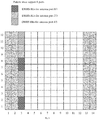
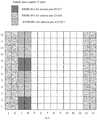
- the pattern shown in Fig. 1 may be used for configuration; and if it exceeds 4 but does not exceed 8, the pattern shown in Fig. 2 may be used for configuration.
- the pattern shown in Fig. 3 may be used for configuration, and if it exceeds 6 but does not exceed 12, the pattern shown in Fig. 4 may be used for configuration.
- the number of ports mentioned here refers to the sum of the numbers of multiplexed ports of all the terminals at each resource position.
- the first two columns represent the control symbol field, i.e., the symbol positions that the downlink control channel needs to occupy, and the last two columns may be the symbol positions that the uplink control channel needs to occupy, i.e., the symbol resources that cannot be used for the Physical Downlink Shared Channel (PDSCH) data channel.
- PDSCH Physical Downlink Shared Channel
- the signals sent by different TRPs/panels may have relatively independent large-scale features, such as average delay, delay spread, average Doppler shift, Doppler spread, spatial domain reception parameters, etc. Therefore, in the NR system, the case where two or more reference signal channels have the same large-scale parameters is called Quasi-Co-Location (QCL). Otherwise, it is called non-QCL.
- the large-scale parameters are, for example, average delay, delay spread, Doppler shift, Doppler spread, spatial reception parameters, average reception power, etc.
- the QCL is further interpreted as follows: the terminal cannot determine that the received reference signal ports come from sites or antenna panels in the same or different physical positions; if two reference signal ports have the same average delay, delay spread, Doppler shift, Doppler spread, spatial reception parameters, average reception power and other parameters (or a subset thereof), it can be considered that these two reference signals are quasi-co-located in the sense of the above-mentioned large-scale parameters.
- QCL group i.e., QCL group of DMRS ports (may be called QCL group for short) is defined in the NR system.
- the DMRS ports in the QCL group are in QCL relationship, while the DMRS ports belonging to different QCL groups are in non-QCL relationship.
- the DMRS ports in the same Code Division Multiplexing (CDM) group have the QCL relationship. That is, in a CDM group, all the reference signal ports occupy the same time-frequency resources and are distinguished by orthogonal code words.
- Each data channel can support two QCL groups.
- the data channel is for example PDSCH.
- the QCL group of DMRS ports described in the embodiments of the present application may be called QCL group for short, or may be called DMRS group.
- the DMRS port described in the embodiments of the present application may be called port for short, or may be called antenna port.
- a data transmission method provided by an embodiment of the present application includes:
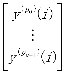
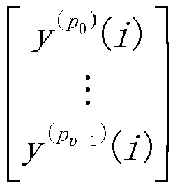
- the vector of DMRS ports is denoted as y p 0 i ⁇ y p ⁇ ⁇ 1 i , and ⁇ P 0 , ..., P v-1 ⁇ represents a set of v DMRS port numbers.
- the value of any element i.e., the value of any port number
- the DMRS port ordering rule is preset in one of the following ways.
- Way 1-3 During single-codeword transmission, the above way 1-1 or way 1-2 is adopted.
- Step 1 grouping DMRS ports among the DMRS ports allocated by the Downlink Control Information (DCI) according to the configured or indicated DMRS QCL grouping parameters, and for each DMRS group:
- DCI Downlink Control Information
- Step 2 sorting across DMRS-groups.
- the "data layer” (i.e., layer) described in the embodiments of the present application refers to the data stream transmitted by MIMO.
- Way 1-4 When one DMRS group is used, the above way 1-1 or way 1-2 is adopted.
- the terminal side may also determine the DMRS port ordering rule in the above ways, which will not be described in detail later.
- the method further includes: sending the DCI to the terminal so that the terminal determines the configuration parameters of the DMRS port according to the DCI.
- the DCI includes, for example, current DMRS high-level configuration parameters, e.g., the DMRS configuration type and the maximum number of DMRS symbols (i.e., the maximum number of consecutive symbols used during the DMRS transmission).
- the DMRS configuration type is, for example, downlink DMRS configuration type (DL-DMRS-config-type), and of course, may be an uplink one.
- the maximum number of DMRS symbols is, for example, the maximum number of downlink DMRS symbols (DL-DMRS-max-len), and of course, may be an uplink one.
- a method for receiving data provided by an embodiment of the present application includes:
- the terminal may determine y p 0 i ⁇ y p ⁇ ⁇ 1 i in one of the following ways.
- the terminal determines a set of DMRS ports used by the terminal for the DMRS configuration type (such as DL-DMRS-config-type) and the maximum number of downlink DMRS symbols (such as DL-DMRS-max-len) (i.e., the maximum number of consecutive symbols used during the DMRS transmission) in the current DMRS high-level configuration parameter according to the received DCI.
- the DMRS configuration type such as DL-DMRS-config-type
- the maximum number of downlink DMRS symbols such as DL-DMRS-max-len
- the terminal determines y p 0 i ⁇ y p ⁇ ⁇ 1 i according to the correspondence between the set of DMRS ports and y p 0 i ⁇ y p ⁇ ⁇ 1 i described and used above (for example, see the lists provided in case 1 or the lists provided in case 2 below).
- Way 3-2 The terminal determines the correspondence among the number of codewords, switch state of each codeword, antenna port indication information field and y p 0 i ⁇ y p ⁇ ⁇ 1 i for the DL-DMRS-config-type and DL-DMRS-max-len in the current DMRS high-level configuration parameters according to the received DCI, and determines y p 0 i ⁇ y p ⁇ ⁇ 1 i .
- the antenna port indication information field is, for example, the value column in the lists provided in case 3 below, i.e., the information field used for indicating the DMRS port allocation in DCI, that is, each value in the value column of the lists in case 3 corresponds to a set of DMRS ports assigned to the terminal in a combination condition of the number of codewords and the switching state thereof, the number of occupied CDM groups, and the number of front-load DMRS symbols used.
- a set of ranked DMRS ports is P 0 to P v-1 .
- case 1 case 1
- case 2 case 2
- case 3 Three cases, i.e., case 1, case 2 and case 3, will be illustrated below respectively.
- the specific values of ⁇ P 0 , ..., P v-1 ⁇ in the DMRS port vector y p 0 i ⁇ y p ⁇ ⁇ 1 i are determined respectively in the ways shown by the following tables case1-1-1, case1-1-2, case1-2-1 and case1-2-2.
- a set of DMRS ports (a column corresponding to the DMRS port (s) of each table in case 1) is determined by the DCI.
- 0-2 in the table indicates that DMRS port 0, DMRS port 1 and DMRS port 2 are included.
- 0-3 in the table indicates that DMRS port 0, DMRS port 1, DMRS port 2 and DMRS port 3 are included.
- the specific values of ⁇ P 0 , ..., P v-1 ⁇ in the DMRS port vector y p 0 i ⁇ y p ⁇ ⁇ 1 i are determined respectively in the ways shown by the tables case2-1-1, case2-1-2, case2-2-1 and case2-2-2.
- the value of the antenna port indication information field and a set of DMRS ports are determined by the DCI.
- the specific values of ⁇ P 0 , ..., P v-1 ⁇ in the DMRS port vector y p 0 i ⁇ y p ⁇ ⁇ 1 i are determined through the correspondence among the number of code words, switch state of each code word, antenna port indication information field (the value column of each table in case 3) and DMRS port vector y p 0 i ⁇ y p ⁇ ⁇ 1 i in the DCI respectively in the ways shown by the tables case3-1-1, case3-1-2, case3-2-1 and case3-2-2.
- a data sending apparatus provided by an embodiment of the present application includes: a memory 520 and a processor 500, where the memory is configured to store the program instructions, and the processor is configured to invoke the program instructions stored in the memory and, in accordance with the obtained program, perform:
- bus interface the transceiver 510 and the like shown in Fig. 7 may be present as optional elements in the data sending apparatus provided by the embodiment of the present application, and are not necessary.
- the DMRS port ordering rule is preset in one of the following ways:
- the processor is further configured to: send the DCI to the terminal via the transceiver so that the terminal determines the configuration parameters of the DMRS port according to the DCI.
- the transceiver 510 is configured to receive and send the data under the control of the processor 500.
- the bus architecture can include any numbers of interconnected buses and bridges, and specifically link various circuits of one or more processors represented by the processor 500 and the memory represented by the memory 520.
- the bus architecture may further link various other circuits such as peripheral device, voltage regulator and power management circuit, which are all well known in the art and thus will not be further described again herein.
- the bus interface provides an interface.
- the transceiver 510 may be a plurality of elements, i.e., include a transmitter and a receiver, and provide the units for communicating with various other devices over the transmission media.
- the processor 500 is responsible for managing the bus architecture and general processing, and the memory 520 may store the data used by the processor 500 when performing the operations.
- the processor 500 may be Central Processing Unit (CPU), Application Specific Integrated Circuit (ASIC), Field-Programmable Gate Array (FPGA) or Complex Programmable Logic Device (CPLD).
- CPU Central Processing Unit
- ASIC Application Specific Integrated Circuit
- FPGA Field-Programmable Gate Array
- CPLD Complex Programmable Logic Device
- an information determining apparatus provided by an embodiment of the present application includes: a memory 620 and a processor 600, where the memory is configured to store the program instructions, and the processor is configured to invoke the program instructions stored in the memory and, in accordance with the obtained program, perform:
- the devices other than the memory 620 and the processor 600 in Fig. 8 are present as optional elements in the data receiving apparatus provided by the embodiment of the present application, and are not required devices.
- the processor 600 in the apparatus at the terminal side may execute any step described in the above data receiving method at the terminal side, and the detailed description thereof will be omitted here.
- the transceiver 610 is configured to receive and send the data under the control of the processor 600.
- the bus architecture may include any numbers of interconnected buses and bridges, and specifically link various circuits of one or more processors represented by the processor 600 and the memory represented by the memory 620.
- the bus architecture may further link various other circuits such as peripheral device, voltage regulator and power management circuit, which are all well known in the art and thus will not be further described again herein.
- the bus interface provides an interface.
- the transceiver 610 may be a plurality of elements, i.e., include a transmitter and a receiver, and provide the units for communicating with various other devices over the transmission media.
- the user interface 630 may also be the interface capable of inter-connecting or exter-connecting with the required devices, and the connected devices include but not limited to keypad, display, loudspeaker, microphone, joystick and the like.
- the processor 600 is responsible for managing the bus architecture and general processing, and the memory 620 may store the data used by the processor 600 when performing the operations.
- the processor 600 may be CPU (Central Processing Unit), ASIC (Application Specific Integrated Circuit), FPGA (Field-Programmable Gate Array) or CPLD (Complex Programmable Logic Device).
- CPU Central Processing Unit
- ASIC Application Specific Integrated Circuit
- FPGA Field-Programmable Gate Array
- CPLD Complex Programmable Logic Device
- another data sending apparatus provided by an embodiment of the present application includes:
- another information determining apparatus provided by an embodiment of the present application includes:
- An embodiment of the present application provides a computer storage medium which is configured to store the computer program instructions used by the above-mentioned computing device, where the computer program instructions contain the program for performing the information indicating or determining method described above.
- the computer storage medium may be any available media or data storage device accessible to the computer, including but not limited to magnetic memory (e.g., floppy disk, hard disk, magnetic tape, Magnetic Optical disc (MO) or the like), optical memory (e.g., CD, DVD, BD, HVD or the like), semiconductor memory (e.g., ROM, EPROM, EEPROM, nonvolatile memory (NAND FLASH), Solid State Disk (SSD)) or the like.
- magnetic memory e.g., floppy disk, hard disk, magnetic tape, Magnetic Optical disc (MO) or the like
- optical memory e.g., CD, DVD, BD, HVD or the like
- semiconductor memory e.g., ROM, EPROM, EEPROM, nonvolatile memory (NAND FLASH), Solid State Disk (SSD)
- the methods provided by the embodiments of the present application may be applied to the terminal devices, and may also be applied to the network devices.
- the terminal device may also referred to as the User Equipment ("UE” for short), Mobile Station (“MS” for short), Mobile Terminal (“MT” for short) or the like.
- the terminal can has the ability of communicating with one or more core networks via the Radio Access Network (RAN).
- the terminal can be a mobile telephone (or called "cellular" telephone), or a computer with the mobile property.
- the terminal can also be a portable, pocket, handheld, computer built-in or vehicle-carried mobile device.
- the network device may be a base station (e.g., access point), which means the device in the access network communicating with the wireless terminal via one or more sectors over the air interface.
- the base station may be used to perform the inter-conversion between the received air frame and the IP packet, and used as the router between the wireless terminal and the rest of the access network, wherein the rest of the access network may include Internet Protocol (IP) networks.
- IP Internet Protocol
- the base station may further coordinate the attribute management of the air interface.
- the base station may be the Base Transceiver Station (BTS) in the GSM or CDMA, or may be the NodeB in the WCDMA, or may be the evolutional Node B (NodeB or eNB or e-NodeB) in the LTE, which is not limited in the embodiments of the invention.
- BTS Base Transceiver Station
- NodeB or eNB or e-NodeB evolutional Node B
- the embodiments of the present application can provide methods, systems and computer program products.
- the present application can take the form of hardware embodiments alone, software embodiments alone, or embodiments combining the software and hardware aspects.
- the present application can take the form of computer program products implemented on one or more computer usable storage mediums (including but not limited to magnetic disk memories, optical memories and the like) containing computer usable program codes therein.
- These computer program instructions can also be stored in a computer readable memory which is capable of guiding the computer or another programmable data processing device to operate in a particular way, so that the instructions stored in the computer readable memory produce a manufacture including the instruction apparatus which implements the functions specified in one or more processes of the flow charts and/or one or more blocks of the block diagrams.
- These computer program instructions can also be loaded onto the computer or another programmable data processing device, so that a series of operation steps are performed on the computer or another programmable device to produce the computer-implemented processing.
- the instructions executed on the computer or another programmable device provide steps for implementing the functions specified in one or more processes of the flow charts and/or one or more blocks of the block diagrams.
Landscapes
- Engineering & Computer Science (AREA)
- Signal Processing (AREA)
- Computer Networks & Wireless Communication (AREA)
- Physics & Mathematics (AREA)
- Quality & Reliability (AREA)
- Electromagnetism (AREA)
- Mathematical Physics (AREA)
- Power Engineering (AREA)
- Mobile Radio Communication Systems (AREA)
- Data Exchanges In Wide-Area Networks (AREA)
Abstract
Description
- The present application claims the priority from Chinese Patent Application No.
201810032484.6 - The present application relates to the field of communication technologies, and particularly to a data transmission method and apparatus and a computer storage medium.
- In the New Radio (NR) system, Demodulation Reference Signal (DMRS) is required for channel estimation during the data demodulation process. In the prior art, the DMRS in the NR system will be transmitted using the same pre-coding scheme as the corresponding data layer.
- The embodiments of the present application provide a data transmission method and apparatus and a computer storage medium, so as to implement the mapping of the data layer to the DMRS port for transmission based on the preset DMRS port ordering rule for transmission.
- At the network side, a method for sending data provided by an embodiment of the present application includes:
- determining a preset DMRS port ordering rule;
- mapping a data layer onto a DMRS port for transmission according to the preset DMRS port ordering rule, and sending the data layer to a terminal.
- With this data sending method, the preset DMRS port ordering rule is determined, and the data layer is mapped onto the DMRS port for transmission according to the preset DMRS port ordering rule and then sent to the terminal, thereby implementing the mapping of the data layer to the DMRS port for transmission based on the preset DMRS port ordering rule for transmission.
- Accordingly, at the terminal side, a method for receiving data provided by an embodiment of the present application includes:
- determining a preset DMRS port ordering rule;
- receiving a data layer mapped onto a DMRS port according to the preset DMRS port ordering rule.
- At the network side, a data sending apparatus provided by an embodiment of the present application includes: a memory and a processor, where the memory is configured to store the program instructions, and the processor is configured to invoke the program instructions stored in the memory and, in accordance with the obtained program, perform:
- determining a preset DMRS port ordering rule;
- mapping a data layer onto a DMRS port for transmission according to the preset DMRS port ordering rule, and sending the data layer to a terminal.
- At the terminal side, a data receiving apparatus provided by an embodiment of the present application includes: a memory and a processor, wherein the memory is configured to store the program instructions, and the processor is configured to invoke the program instructions stored in the memory and, in accordance with the obtained program, perform:
- determining a preset DMRS port ordering rule;
- receiving a data layer mapped onto a DMRS port according to the preset DMRS port ordering rule.
- At the network side, another data sending apparatus provided by an embodiment of the present application includes:
- a determining unit configured to determine a preset DMRS port ordering rule;
- a sending unit configured to map a data layer onto a DMRS port for transmission according to the preset DMRS port ordering rule, and sending the data layer to a terminal.
- At the terminal side, another data receiving apparatus provided by an embodiment of the present application includes:
- a determining unit configured to determine a preset DMRS port ordering rule;
- a receiving unit configured to receive a data layer mapped onto a DMRS port according to the preset DMRS port ordering rule.
- Another embodiment of the present application provides a computer storage medium storing the computer executable instructions which are configured to cause the computer to perform any one of the above-mentioned methods.
- In order to illustrate the technical solutions in the embodiments of the present application more clearly, the accompanying figures which need to be used in describing the embodiments will be introduced below briefly. Obviously the accompanying figures described below are only some embodiments of the present application, and other accompanying figures can also be obtained by those ordinary skilled in the art according to these accompanying figures without creative labor.
-
Fig. 1 is a schematic diagram of a first DMRS pattern provided by an embodiment of the present application; -
Fig. 2 is a schematic diagram of a second DMRS pattern provided by an embodiment of the present application; -
Fig. 3 is a schematic diagram of a third DMRS pattern provided by an embodiment of the present application; -
Fig. 4 is a schematic diagram of a fourth DMRS pattern provided by an embodiment of the present application; -
Fig. 5 is a flow schematic diagram of a method for sending data provided by an embodiment of the present application; -
Fig. 6 is a flow schematic diagram of a method for receiving data provided by an embodiment of the present application; -
Fig. 7 is a structural schematic diagram of an apparatus for sending data provided by an embodiment of the present application; -
Fig. 8 is a structural schematic diagram of an apparatus for receiving data provided by an embodiment of the present application; -
Fig. 9 is a structural schematic diagram of another apparatus for sending data provided by an embodiment of the present application; -
Fig. 10 is a structural schematic diagram of another apparatus for receiving data provided by an embodiment of the present application. - The embodiments of the present application provide a data transmission method and apparatus and a computer storage medium, so as to implement the mapping of the data layer to the DMRS port for transmission based on the preset DMRS port ordering rule for transmission.
- The basic DMRS pattern (front-load DMRS) configuration includes the following cases.
- The number of DMRS symbols is 1: combination (comb) 2 + Cyclic Shift (CS) 2, up to 4 ports.
- Referring to
Fig. 1 , comb2 refers to frequency domain multiplexing. For example, the multiplexing relationship of comb2 exists betweenports 0 and 2. CS2 refers to multiplexing of the sequence between ports by way of Cyclic Shifting (CS). For example, the multiplexing relationship of CS2 exists betweenports 0 and 1. - The number of DMRS symbols is 2: comb2 + CS2 + TD-OCC ({1, 1} and {1, -1}), up to 8 ports. Here TD-OCC ({1, 1} and {1, -1}) indicates that the Time Domain Orthogonal Cover Code (TD-OCC) multiplexing is used between two ports, and {1, 1} and {1, -1} are the multiplexing coefficients for the two ports respectively.
- Referring to
Fig. 2 , TD-OCC refers to time domain Orthogonal Cover Code (OCC) multiplexing. For example, the time domain OCC multiplexing is used between ports 0/1 and 4/5. Here the CS2 multiplexing exists between port 0 andport 1, the CS2 multiplexing exists betweenport 4 andport 5, and the time domain OCC multiplexing exists between port 0/1 andport 4/5. - The number of DMRS symbols is 1: 2-FD-OCC (across adjacent Resource Elements (REs) in the frequency domain), up to 6 ports.
- Referring to
Fig. 3 , 2-FD-OCC refers to frequency domain OCC multiplexing. For example, the frequency domain OCC multiplexing exists betweenports 0 and 1. In addition, the Frequency-Division Multiplexing (FDM) is used between the ports 0/1 and other ports, for example, the FDM mode is used between ports 0/1 and 2/3. - The number of DMRS symbols is 2: 2-FD-OCC (across adjacent REs in the frequency domain) + TD-OCC ({1, 1} and {1, -1}), up to 12 ports.
- Referring to
Fig. 4 , TD-OCC refers to time domain OCC multiplexing, for example, the time domain OCC multiplexing is used between ports 0/1 and 6/7. - As can be seen from various DMRS patterns described above, in the case of configuration 1: if the maximum number of ports supported does not exceed 4, the pattern shown in
Fig. 1 may be used for configuration; and if it exceeds 4 but does not exceed 8, the pattern shown inFig. 2 may be used for configuration. In the case ofconfiguration 2, if the maximum number of ports supported does not exceed 6, the pattern shown inFig. 3 may be used for configuration, and if it exceeds 6 but does not exceed 12, the pattern shown inFig. 4 may be used for configuration. The number of ports mentioned here refers to the sum of the numbers of multiplexed ports of all the terminals at each resource position. - As a supplementary note, in
Figs. 1 to 4 , the first two columns represent the control symbol field, i.e., the symbol positions that the downlink control channel needs to occupy, and the last two columns may be the symbol positions that the uplink control channel needs to occupy, i.e., the symbol resources that cannot be used for the Physical Downlink Shared Channel (PDSCH) data channel. - In an NR system, there may be a need to consider a case of cooperative transmission of multiple Transmission/Reception Points (TRPs)/antenna panels or subarrays. In this case, the signals sent by different TRPs/panels may have relatively independent large-scale features, such as average delay, delay spread, average Doppler shift, Doppler spread, spatial domain reception parameters, etc. Therefore, in the NR system, the case where two or more reference signal channels have the same large-scale parameters is called Quasi-Co-Location (QCL). Otherwise, it is called non-QCL. Here, the large-scale parameters are, for example, average delay, delay spread, Doppler shift, Doppler spread, spatial reception parameters, average reception power, etc. Furthermore, the QCL is further interpreted as follows: the terminal cannot determine that the received reference signal ports come from sites or antenna panels in the same or different physical positions; if two reference signal ports have the same average delay, delay spread, Doppler shift, Doppler spread, spatial reception parameters, average reception power and other parameters (or a subset thereof), it can be considered that these two reference signals are quasi-co-located in the sense of the above-mentioned large-scale parameters.
- For the DMRS ports, QCL group, i.e., QCL group of DMRS ports (may be called QCL group for short) is defined in the NR system. The DMRS ports in the QCL group are in QCL relationship, while the DMRS ports belonging to different QCL groups are in non-QCL relationship. It is specified in the NR system that the DMRS ports in the same Code Division Multiplexing (CDM) group have the QCL relationship. That is, in a CDM group, all the reference signal ports occupy the same time-frequency resources and are distinguished by orthogonal code words. Taking
Fig. 4 as an example, due to the characteristics of the DMRS design, when there is one DMRS symbol, the port 0/1 has the CDM relationship, theport 2/3 has the CDM relationship, and there is the FDM relationship between the port 0/1 andport 2/3. InFigs. 1 to 4 , adjacent blocks with the same filling pattern form a CDM group. Each data channel can support two QCL groups. The data channel is for example PDSCH. - The QCL group of DMRS ports described in the embodiments of the present application may be called QCL group for short, or may be called DMRS group.
- The DMRS port described in the embodiments of the present application may be called port for short, or may be called antenna port.
- The specific solution provided by an embodiment of the present application includes the following.
- Referring to
Fig. 5 , at the network side, e.g., at the base station side, a data transmission method provided by an embodiment of the present application includes: - S101: determining a preset DMRS port ordering rule;
- S102: mapping a data layer onto a DMRS port for transmission according to the preset DMRS port ordering rule, and sending the data layer to the terminal.
- Optionally, in an embodiment of the present application, the vector of DMRS ports is denoted as

- Optionally, mapping a data layer onto a DMRS port for transmission according to the preset DMRS port ordering rule and then sending the data layer to the terminal, specifically includes:
mapping v data layers onto v DMRS ports according to the following formula and then sending the data layers to the terminal:


0 )(i) for transmission for sending to the terminal, and so on, mapping a data layer x (v-1)(i) onto a DMRS port y (pv-1 )(i) for transmission for sending to the terminal. - Optionally, the DMRS port ordering rule is preset in one of the following ways.
- Way 1-1: sorting based on the order of DMRS port numbers contained in a DMRS port vector from smallest to largest.
- Way 1-2: sorting CDM groups to which the DMRS ports contained in the DMRS port vector belong, based on the CDM group numbers; for example:
- when two CDM groups are involved, the order may be 0, 1 or 1, 0;
- when three CDM groups are involved, the order may be 0, 1, 2 or 0, 2, 1 or 1, 0, 2 or 1, 2, 0 or 2, 0, 1 or 2, 1, 0;
- and for each CDM group, sorting the DMRS ports in the group based on the DMRS port numbers; for example, sorting in the order of the DMRS port numbers from smallest to largest.
- Way 1-3:
During single-codeword transmission, the above way 1-1 or way 1-2 is adopted. - During dual-codeword transmission, two steps below are included.
- Step 1: grouping DMRS ports among the DMRS ports allocated by the Downlink Control Information (DCI) according to the configured or indicated DMRS QCL grouping parameters, and for each DMRS group:
- sorting DMRS ports in the order of DMRS port numbers from smallest to largest, or
- sorting CDM groups to which DMRS ports in the DMRS-group belong, based on the CDM group numbers, and sorting in the order of DMRS port numbers from smallest to largest in each CDM group.
- Step 2: sorting across DMRS-groups.
- When the number of data layers is odd:
- placing groups containing a smaller number of DMRS ports in front positions, or
- sorting all DMRS groups based on the DMRS group number, for example: in an order of DMRS-groupl, DMRS-group2 or DMRS-group2, DMRS-groupl, and sorting the corresponding DMRS groups.
- The "data layer" (i.e., layer) described in the embodiments of the present application refers to the data stream transmitted by MIMO.
- When the number of data layers is even:
- ensuring that a set of DMRS ports (corresponding to one DMRS-group) corresponding to the
codeword 1 is the same as a set of DMRS ports (corresponding to one DMRS-group) corresponding to thecodeword 1 when the number of layers minus 1, and a set of DMRS ports (corresponding to one DMRS-group) corresponding to the codeword 0 contains a set of DMRS ports (corresponding to one DMRS-group) corresponding to the codeword 0 when the number of layers minus 1. Taking the following table case2-2-2 as an example, the cases of the dual-codeword and value = 2 and 3 correspond to rank5 and rank6, respectively. In the case of rank5, the occupied ports are 0, 1, 2, 3, 6, and the order is 23016. According to the current mapping relationship between codewords and layers, the codeword 0 is mapped toports codeword 1 is mapped toports codeword 1 still usesports port 8 is added to a set of ports used by the codeword 0; - or, sorting all DMRS groups based on the DMRS group numbers, for example: DMRS-groupl, DMRS-group2 or DMRS-group2, DMRS-groupl, and sorting the corresponding DMRS groups.
- Way 1-4:
When one DMRS group is used, the above way 1-1 or way 1-2 is adopted. - When two DMRS groups are used:
- grouping DMRS ports among the DMRS ports allocated by the DCI based on the high-level configured DMRS QCL grouping parameters (for example, among the DMRS ports allocated by the DCI, those belonging to DMRS-group1 are divided into one group, and those belonging to DMRS-group2 are divided into one group), and for each DMRS group: sorting the DMRS ports in the order of DMRS port numbers from smallest to largest, or sorting the CDM groups to which the DMRS ports in the DMRS group belong, based on the CDM group numbers, and sorting in the order of DMRS port numbers from smallest to largest in each CDM group;
- placing the DMRS groups containing a smaller number of DMRS ports in the front positions.
- It should be noted that the above ways are also applicable to the method at the terminal side, that is, the terminal side may also determine the DMRS port ordering rule in the above ways, which will not be described in detail later.
- Optionally, the method further includes:
sending the DCI to the terminal so that the terminal determines the configuration parameters of the DMRS port according to the DCI. The DCI includes, for example, current DMRS high-level configuration parameters, e.g., the DMRS configuration type and the maximum number of DMRS symbols (i.e., the maximum number of consecutive symbols used during the DMRS transmission). Here the DMRS configuration type is, for example, downlink DMRS configuration type (DL-DMRS-config-type), and of course, may be an uplink one. The maximum number of DMRS symbols is, for example, the maximum number of downlink DMRS symbols (DL-DMRS-max-len), and of course, may be an uplink one. - Accordingly, at the terminal side, referring to
Fig. 6 , a method for receiving data provided by an embodiment of the present application includes: - S201: determining a preset DMRS port ordering rule;
- S202: receiving a data layer mapped onto a DMRS port according to the preset DMRS port ordering rule.
- Optionally, receiving the data layer mapped onto the DMRS port according to the preset DMRS port ordering rule, specifically includes:
receiving the data layer mapped onto the DMRS port for transmission according to the following formula: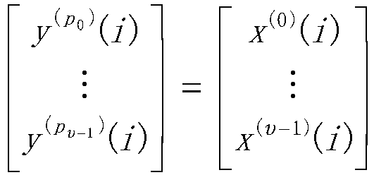
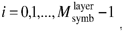
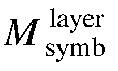


v-1 )(i) used during transmission. - Optionally, the terminal may determine

- Way 3-1:
The terminal determines a set of DMRS ports used by the terminal for the DMRS configuration type (such as DL-DMRS-config-type) and the maximum number of downlink DMRS symbols (such as DL-DMRS-max-len) (i.e., the maximum number of consecutive symbols used during the DMRS transmission) in the current DMRS high-level configuration parameter according to the received DCI. - The terminal determines


case 1 or the lists provided incase 2 below). - Way 3-2:
The terminal determines the correspondence among the number of codewords, switch state of each codeword, antenna port indication information field and

- Here, the antenna port indication information field is, for example, the value column in the lists provided in
case 3 below, i.e., the information field used for indicating the DMRS port allocation in DCI, that is, each value in the value column of the lists incase 3 corresponds to a set of DMRS ports assigned to the terminal in a combination condition of the number of codewords and the switching state thereof, the number of occupied CDM groups, and the number of front-load DMRS symbols used. For example, in thecase 3, a set of ranked DMRS ports is P0 to Pv-1. - Three cases, i.e.,
case 1,case 2 andcase 3, will be illustrated below respectively. - According to the high-level configuration parameters DL-DMRS-config-type and DL-DMRS-max-len, the specific values of {P0, ..., Pv-1} in the DMRS port vector

- Here, a set of DMRS ports (a column corresponding to the DMRS port (s) of each table in case 1) is determined by the DCI.
- If the high-level configured DMRS configuration parameters are: DL-DMRS-config-type = 1 and DL-DMRS-max-len = 1, the specific values of {P0, ..., Pv-1} in the DMRS port vector
- Optionally, when the DMRS configuration type is the first type (e.g., DL-DMRS-config-type = 1) and the maximum number of DMRS symbols is 1 (e.g., DL-DMRS-max-len = 1), the values of {P0, ..., Pv-1} are determined by the Table case1-1-1:
Table case1-1-1 DMRS port(s) {P0, ..., Pv-1} 0 p 0 = 0 1 p 0 = 1 0,1 p 0 = 0 p 1 = 1 2 p 0 = 2 3 p 0 = 3 2,3 p 0 = 2 p 1 = 3 0-2 p 0 = 0 p 1 = 1 p 2 = 2 or p 0 = 2 p 1 = 0 p 2 = 1 0-3 p 0 = 0 p 1 = 1 p 2 = 2 p 3 = 3 or p 0 = 2 p 1 = 3 p 2 = 0 p 3 = 1 0,2 p 0 = 0 p 1 = 2 or p 0 = 2 p 1 = 0 - 0-2 in the table indicates that DMRS port 0,
DMRS port 1 andDMRS port 2 are included. 0-3 in the table indicates that DMRS port 0,DMRS port 1,DMRS port 2 andDMRS port 3 are included. Those in the following tables are explained in the same way, and will not be described in detail later. - If the high-level configured DMRS configuration parameters are: DL-DMRS-config-type = 1 and DL-DMRS-max-len = 2, the specific values of {P0, ..., Pv-1} in the DMRS port vector

- That is, optionally, when the DMRS configuration type is the first type (e.g., DL-DMRS-config-type = 1) and the maximum number of DMRS symbols is 2 (e.g., DL-DMRS-max-len = 2), the values of {P0, ..., Pv-1} are determined by the Table case1-1-2 below:
Table case1-1-2 DMRS port(s) {P0, ..., Pv-1} 0 p 0 = 0 1 p 0 = 1 0,1 p 0 = 0 p 1 = 1 2 p 0 = 2 3 p 0 = 3 2,3 p 0 = 2 p 1 = 3 0-2 p 0 = 0 p 1 = 1 p 2 = 2 or p 0 = 2 p 1 = 0 p 2 = 1 0-3 p 0 = 0 p 1 = 1 p 2 = 2 p 3 = 3 or p 0 = 2 p 1 = 3 p 2 = 0 p 3 = 1 0,2 p 0 = 0 p 1 = 2 or p 0 = 2 p 1 = 0 4 p 0 = 4 5 p 0 = 5 6 p 0 = 6 7 p 0 = 7 4,5 p 0 = 4 p 1 = 5 6,7 p 0 = 6 p 1 = 7 0,4 p 0 = 0 p 1 = 4 2,6 p 0 = 2 p 1 = 6 0,1,4 p 0 = 0 p 1 = 1 p 2 = 4 2,3,6 p 0 = 2 p 1 = 3 p 2 = 6 0,1,4,5 p 0 = 0 p 1 = 1 p 2 = 4 p 3 = 5 2,3,6,7 p 0 = 2 p1 = 3 p 2 = 6 p 3 = 7 0,2,4,6 p 0 = 0 p 1 = 2 p 2 = 4 p 3 = 6 or p 0 = 2 p 1 = 6 p 2 = 0 p 3 = 4 or p 0 = 0 p 1 = 4 p 2 = 2 p 3 = 6 0-4 p 0 = 2 p 1 = 3 p 2 = 0 p 3 = 1 p 4 = 4 or p 0 = 0 p 1 = 1 p 2 = 2 p 3 = 3 p 4 = 4 0,1,2,3,4,6 p 0 = 2 p 1 = 3 p 2 = 6 p 3 = 0 p 4 = 1 p 5 = 4 or p 0 = 0 p 1 = 1 p 2 = 4 p 3 = 2 p 4 = 3 p 5 = 6 or p 0 = 0 p 1 = 1 p 2 = 2 p 3 = 3 p 4 = 4 p 5 = 6 0,1,2,3,4,5,6 p 0 = 2 p 1 = 3 p 2 = 6 p 3 = 0 p 4 = 1 p 5 = 4 p 6 = 5 or p 0 = 0 p 1 = 1 p 2 = 2 p 3 = 3 p 4 = 4 p 5 = 5 p 6 = 6 0,1,2,3,4,5,6,7 p 0 = 2 p 1 = 3 p 2 = 6 p 3 = 7 p 4 = 0 p 5 = 1 p 6 = 4 p 7 = 5 or p 0 = 0 p 1 = 1 p 2 = 4 p 3 = 5 p 4 = 2 p 5 = 3 p 6 = 6 p 7 = 7 or p 0 = 0 p 1 = 1 p 2 = 2 p 3 = 3 p 4 = 4 p 5 = 5 p 6 = 6 p 7 = 7 - If the high-level configured DMRS configuration parameters are: DL-DMRS-config-type = 2 and DL-DMRS-max-len = 1, the specific values of {P0, ..., Pv-1} in the DMRS port vector

- That is, optionally, when the DMRS configuration type is the second type (e.g., DL-DMRS-config-type = 2) and the maximum number of DMRS symbols is 1 (e.g., DL-DMRS-max-len = 1), the values of {P0, ..., Pv-1} are determined by the Table case1-2-1 below:
Table case1-2-1 DMRS port(s) {P0, ..., Pv-1} 0 p 0 = 0 1 p 0 = 1 0,1 p 0 = 0 p 1 = 1 2 p 0 = 2 3 p 0 = 3 2,3 p 0 = 2 p 1 = 3 0-2 p 0 = 0 p 1 = 1 p 2 = 2 or p 0 = 2 p 1 = 0 p 2 = 1 0-3 p 0 = 0 p 1 = 1 p 2 = 2 p 3 = 3 or p 0 = 2 p 1 = 3 p 2 = 0 p 3 = 1 4 p 0 = 4 5 p 0 = 5 4,5 p 0 = 4 p 1 = 5 3-5 p 0 = 3 p 1 = 4 p 2 = 5 or p 0 = 4 p 1 = 5 p 2 = 3 0-3 p 0 = 0 p 1 = 1 p 2 = 2 p 3 = 3 or p 0 = 2 p 1 = 3 p 2 = 0 p 3 = 1 0,2 p 0 = 0 p 1 = 2 or p 0 = 2 p 1 = 0 0-4 p 0 = 0 p 1 = 1 p 2 = 2 p 3 = 3 p 4 = 4 0-5 p 0 = 0 p 1 = 1 p 2 = 2 p 3 = 3 p 4 = 4 p 4 = 5 or p 0 = 0 p 1 = 1 p 2 = 4 p 3 = 5 p 4 = 2 p 4 = 3 or p 0 = 2 p 1 = 3 p 2 = 0 p 3 = 1 p 4 = 4 p 4 = 5 or p 0 = 2 p 1 = 3 p 2 = 4 p 3 = 5 p 4 = 0 p 4 = 1 or p 0 = 4 p 1 = 5 p 2 = 0 p 3 = 1 p 4 = 2 p 4 = 3 or p 0 = 4 p 1 = 5 p 2 = 2 p 3 = 3 p4 = 0 p 4 = 1 - If the high-level configured DMRS configuration parameters are: DL-DMRS-config-type = 2 and DL-DMRS-max-len = 2, the specific values of {P0, ..., Pv-1} in the DMRS port vector

- That is, optionally, when the DMRS configuration type is the second type (e.g., DL-DMRS-config-type = 2) and the maximum number of DMRS symbols is 2 (e.g., DL-DMRS-max-len = 2), the values of {P0, ..., Pv-1} are determined by the Table case1-2-2 below:
Table case 1-2-2 DMRS port(s) {P0, ..., Pv-1} 0 p 0 = 0 1 p 0 = 1 0,1 p 0 = 0 p 1 = 1 2 p 0 = 2 3 p 0 = 3 0,1 p 0 = 0 p 1 = 1 2,3 p 0 = 2 p 1 = 3 0-2 p 0 = 0 p 1 = 1 p 2 = 2 or p 0 = 2 p 1 = 0 p 2 = 1 0-3 p 0 = 0 p 1 = 1 p 2 = 2 p 3 = 3 or p 0 = 2 p 1 = 3 p 2 = 0 p 3 = 1 4 p 0 = 4 5 p 0 = 5 4,5 p 0 = 4 p 1 = 5 3-5 p 0 = 3 p 1 = 4 p 2 = 5 or p 0 = 5 p 1 = 3 p 2 = 4 0-3 p 0 = 0 p 1 = 1 p 2 = 2 p 3 = 3 or p 0 = 2 p 1 = 3 p 2 = 0 p 3 = 1 0,2 p 0 = 0 p 1 = 2 or p 0 = 2 p 1 = 0 6 p 0 = 6 7 p 0 = 7 8 p 0 = 8 9 p 0 = 9 10 p 0 = 10 11 p 0 = 11 6,7 p 0 = 6 p 1 = 7 8,9 p 0 = 8 p 1 = 9 10,11 p 0 = 10 p 1 = 11 0,1,6 p 0 = 0 p 1 = 1 p 2 = 6 2,3,8 p 0 = 2 p 1 = 3 p 2 = 8 4,5,10 p 0 = 4 p 1 = 5 p 2 = 10 0,1,6,7 p 0 = 0 p 1 = 1 p 2 = 6 p 3 = 7 2,3,8,9 p 0 = 2 p 1 = 3 p 2 = 8 p 3 = 9 4,5,10,11 p 0 = 4 p 1 = 5 p 2 = 10 p 3 = 11 0-4 p 0 = 0 p 1 = 1 p 2 = 2 p 3 = 3 p 4 = 4 0-5 p 0 = 0 p 1 = 1 p 2 = 2 p 3 = 3 p 4 = 4 p 4 = 5 or p 0 = 0 p 1 = 1 p 2 = 4 p 3 = 5 p 4 = 2 p 4 = 3 or p 0 = 2 p 1 = 3 p 2 = 0 p 3 = 1 p 4 = 4 p 4 = 5 or p 0 = 2 p 1 = 3 p 2 = 4 p 3 = 5 P4 = 0 P4 = 1 or p 0 = 4 p 1 = 5 p 2 = 0 p 3 = 1 p 4 = 2 p 4 = 3 or p 0 = 4 p 1 = 5 p 2 = 2 p 3 = 3 p 4 = 0 p 4 = 1 0,1,2,3,6 p 0 = 2 p 1 = 3 p 2 = 0 p 3 = 1 p 4 = 6 or p 0 = 0 p 1 = 1 p 2 = 2 p 3 = 3 p 4 = 6 0,1,2,3,6,8 p 0 = 2 p 1 = 3 p 2 = 8 p 3 = 0 p 4 = 1 p 5 = 6 or p 0 = 0 p 1 = 1 p 2 = 6 p 3 = 2 p 4 = 3 p 5 = 8 or p 0 = 0 p 1 = 1 p 2 = 2 p 3 = 3 p 4 = 6 p 5 = 8 0,1,2,3,6,7,8 p 0 = 2 p 1 = 3 p 2 = 8 p 3 = 0 p 4 = 1 p 5 = 6 p 6 = 7 or p 0 = 0 p 1 = 1 p 2 = 2 p 3 = 3 p 4 = 6 p 5 = 7 p 6 = 8 0,1,2,3,6,7,8,9 p 0 = 2 p 1 = 3 p 2 = 8 p 3 = 9 p 4 = 0 p 5 = 1 p 6 = 6 p 7 = 7 or p 0 = 0 p 1 = 1 p 2 = 6 p 3 = 7 p 4 = 2 p 5 = 3 p 6 = 8 p 7 = 9 or p 0 = 0 p 1 = 1 p 2 = 2 p 3 = 3 p 4 = 6 p 5 = 7 p 6 = 8 p 7 = 9 - According to the high-level configuration parameters DL-DMRS-config-type and DL-DMRS-max-len, the specific values of {P0, ..., Pv-1} in the DMRS port vector

- Here, the value of the antenna port indication information field and a set of DMRS ports (a column corresponding to the DMRS port (s) of each table in case 2) are determined by the DCI.
- If the high-level configured DMRS configuration parameters are: DL-DMRS-config-type = 1 and DL-DMRS-max-len = 1, the specific values of {P0, ..., Pv-1} in the DMRS port vector

- That is, optionally, when the DMRS configuration type is the first type and the maximum number of DMRS symbols is 1, the values of {P0, ..., Pv-1} are determined by the Table case2-1-1:
Table case2-1-1 One Codeword: Codeword 0 enabled, Codeword 1 disabled Value Number of DMRS CDM group(s) without data DMRS port(s) {P0, ..., Pv-1} 0 1 0 p 0 = 0 1 1 1 p 0 = 1 2 1 0,1 p 0 = 0 p 1 = 1 3 2 0 p 0 = 0 4 2 1 p 0 = 1 5 2 2 p 0 = 2 6 2 3 p 0 = 3 7 2 0,1 p 0 = 0 p 1 = 1 8 2 2,3 p 0 = 2 p 1 = 3 9 2 0-2 p 0 = 0 p 1 = 1 p 2 = 2 or p 0 = 2 p 1 = 0 p 2 = 1 10 2 0-3 p 0 = 0 p 1 = 1 p 2 = 2 p 3 = 3 or p 0 = 2 p 1 = 3 p 2 = 0 p 3 = 1 11 2 0,2 p 0 = 0 p 1 = 2 or p 0 = 2 p 1 = 0 12-15 Reserved Reserved - If the high-level configured DMRS configuration parameters are: DL-DMRS-config-type = 1 and DL-DMRS-max-len = 2, the specific values of {P0, ..., Pv-1} in the DMRS port vector

- That is, optionally, when the DMRS configuration type is the first type and the maximum number of DMRS symbols is 2 the values of {P0, ..., Pv-1} are determined by the Table case2-1-2:
Table case2-1-2 One Codeword: Two Codewords: Codeword 0 enabled, Codeword 0 enabled, Codeword 1 disabled Codeword 1 enabled Value Number of DMRS CDM group(s) without data DMRS port(s) {P0, ..., Pv- 1} Number of front-load symbols Value Number of DMRS CDM group(s) without data DMRS port(s) {P0, ..., Pv-1} Number of front-load symbols 0 1 0 p 0 = 0 1 0 2 0-4 p 0 = 2 2 p 1 = 3 p 2 = 0 p 3 = 1 p 4 = 4 or p 0 = 0 p 1 = 1 p 2 = 2 p 3 = 3 p 4 = 4 p 0 = 2 p 1 = 3 p 2 = 6 p 3 = 0 p 4 = 1 p 5 = 4 or p 0 = 0 p 1 = 1 1 1 1 p 0 = 1 1 1 2 0,1,2,3,4,6 p 2 = 4 2 p 3 = 2 p 4 = 3 p 5 = 6 or p 0 = 0 p 1 = 1 p 2 = 2 p 3 = 3 p 4 = 4 p 5 = 6 2 1 0,1 1 2 2 0,1,2,3,4,5,6 p 0 = 2 p 1 = 3 p 2 = 6 p 3 = 0 p 4 = 1 p 5 = 4 p 6 = 5 p 0 = 0 or 2 p 1 = 1 p 0 = 0 p 1 = 1 p 2 = 2 p 3 = 3 p 4 = 4 p 5 = 5 p 6 = 6 p 0 = 2 p 1 = 3 p 2 = 6 p 3 = 7 p 4 = 0 p 5 = 1 p 6 = 4 p 7 = 5 or p 0 = 0 p 1 = 1 p 2 = 4 p 3 = 5 p 4 = 2 p 5 = 3 p 6 = 6 p 7 = 7 or p 0 = 0 3 2 0 p 0 = 0 1 3 2 0,1,2,3,4,5,6,7 p 1 = 1 2 p 2 = 2 p 3 = 3 p 4 = 4 p 5 = 5 p 6 = 6 p 7 = 7 4 2 1 p 0 = 1 1 4-31 reserved reserved reserved 5 2 2 p 0 = 2 1 6 2 3 p 0 = 3 1 7 2 0,1 p 0 = 0 1 p 1 = 1 8 2 2,3 p 0 = 2 1 p 1 = 3 9 2 0-2 p 0 = 0 1 p 1 = 1 p 2 = 2 or p 0 = 2 p 1 = 0 p 2 = 1 10 2 0-3 p 0 = 0 1 p 1 = 1 p 2 = 2 p 3 = 3 or p 0 = 2 p 1 = 3 p 2 = 0 p 3 = 1 11 2 0,2 p 0 = 0 1 p 1 = 2 or p 0 = 2 p 1 = 0 12 2 0 p 0 = 0 2 13 2 1 p 0 = 1 2 14 2 2 p 0 = 2 2 15 2 3 p 0 = 3 2 16 2 4 p 0 = 4 2 17 2 5 p 0 = 5 2 18 2 6 p 0 = 6 2 19 2 7 p 0 = 7 2 20 2 0,1 p 0 = 0 2 p 1 = 1 21 2 2,3 p 0 = 2 2 p 1 = 3 22 2 4,5 p 0 = 4 2 p 1 = 5 23 2 6,7 p 0 = 6 2 p 1 = 7 24 2 0,4 p 0 = 0 2 p 1 = 4 25 2 2,6 p 0 = 2 2 p 1 = 6 26 2 0,1,4 p 0 = 0 2 p 1 = 1 p 2 = 4 27 2 2,3,6 p 0 = 2 2 p 1 = 3 p 2 =6 28 2 0,1,4,5 p 0 = 0 2 p 1 = 1 p 2 = 4 p 3 = 5 29 2 2,3,6,7 p 0 = 2 2 p 1 = 3 p 2 = 6 p 3 = 7 30 2 0,2,4,6 p 0 = 0 2 p 1 = 2 p 2 = 4 p 3 = 6 or p 0 = 2 p 1 = 6 p 2 = 0 p 3 = 4 or p 0 = 0 p 1 = 4 p 2 = 2 p3 = 6 31 Reserved Reserved Reserved - If the high-level configured DMRS configuration parameters are: DL-DMRS-config-type = 2 and DL-DMRS-max-len = 1, the specific values of {P0, ..., Pv-1} in the DMRS port vector

- That is, optionally, when the DMRS configuration type is the second type and the maximum number of DMRS symbols is 1 the values of {P0, ..., Pv-1} are determined by the Table case2-2-1:
Table case2-2-1 One codeword: Two codewords: Codeword 0 enabled, Codeword 0 enabled, Codeword 1 disabled Codeword 1 enabled Value Number of DMRS CDM group(s) without data DMRS port(s) {P0, ..., Pv-1} Value Number of DMRS CDM group(s) without data DMRS port(s) {P0, ..., Pv-1} 0 1 0 p 0 = 0 0 3 0-4 p 0 = 0 p 1 = 1 p 2 = 2 p 3 = 3 p 4 = 4 p 0 = 0 p 1 = 1 p 2 = 2 p 3 = 3 p 4 = 4 p 4 = 5 or p 0 = 0 p 1 = 1 p 2 = 4 p 3 = 5 p 4 = 2 p 4 = 3 or p 0 = 2 1 1 1 p 0 = 1 1 3 0-5 p 1 = 3 p 2 = 0 p 3 = 1 p 4 = 4 p 4 = 5 or p 0 = 2 p 1 = 3 p 2 = 4 p 3 = 5 p 4 = 0 p 4 = 1 or p 0 = 4 p 1 = 5 p 2 = 0 p 3 = 1 p 4 = 2 p 4 = 3 or p 0 = 4 p 1 = 5 p 2 = 2 p 3 = 3 p 4 = 0 p 4 = 1 2 1 0,1 p 0 = 0 2-31 reserved reserved p 1 = 1 3 2 0 p 0 = 0 4 2 1 p 0 = 1 5 2 2 p 0 = 2 6 2 3 p 0 = 3 7 2 0,1 p 0 = 0 p 1 = 1 8 2 2,3 p 0 = 2 p 1 = 3 9 2 0-2 p 0 = 0 p 1 = 1 p 2 = 2 or p 0 = 2 p 1 = 0 p 2 = 1 10 2 0-3 p 0 = 0 p 1 = 1 p 2 = 2 p 3 = 3 or p 0 = 2 p 1 = 3 p 2 = 0 p 3 = 1 11 3 0 p 0 = 0 12 3 1 p 0 = 1 13 3 2 p 0 = 2 14 3 3 p 0 = 3 15 3 4 p 0 = 4 16 3 5 p 0 = 5 17 3 0,1 p 0 = 0 p 1 = 1 18 3 2,3 p 0 = 2 p 1 = 3 19 3 4,5 p 0 = 4 p 1 = 5 20 3 0-2 p 0 = 0 p 1 = 1 p 2 = 2 or p 0 = 2 p 1 = 0 p 2 = 1 21 3 3-5 p 0 = 3 p 1 = 4 p 2 = 5 or p 0 = 4 p 1 = 5 p 2 = 3 22 3 0-3 p 0 = 0 p 1 = 1 p 2 = 2 p 3 = 3 or p 0 = 2 p 1 = 3 p 2 = 0 p 3 = 1 23 2 0,2 p 0 = 0 p 1 = 2 or p 0 = 2 p 1 = 0 24-31 Reserved Reserved - If the high-level configured DMRS configuration parameters are: DL-DMRS-config-type = 2 and DL-DMRS-max-len = 2, the specific values of {P0, ..., Pv-1} in the DMRS port vector

- That is, optionally, when the DMRS configuration type is the second type and the maximum number of DMRS symbols is 2, the values of {P0, ..., Pv-1} are determined by the Table case2-2-2:
Table case2-2-2 One codeword: Two Codewords: Codeword 0 enabled, Codeword 0 enabled, Codeword 1 disabled Codeword 1 enabled Value Number of DMRS CDM group(s) without data DMRS port(s) {P0, ..., Pv-1} Number of front-load symbols Value Number of DMRS CDM group(s) without data DMRS port(s) {P0, ..., Pv-1} Number of front-load symbols 0 1 0 p 0 = 0 1 0 3 0-4 p 0 = 0 1 p 1 = 1 p 2 = 2 p 3 = 3 p 4 = 4 p 0 = 0 p 1 = 1 p 2 = 2 p 3 = 3 p 4 = 4 p 4 = 5 or p 0 = 0 p 1 = 1 p 2 = 4 p 3 = 5 p 4 = 2 p 4 = 3 or p 0 = 2 p 1 = 3 p 2 = 0 p 3 = 1 p 4 = 4 p 4 = 5 1 1 1 p 0 = 1 1 1 3 0-5 or 1 p 0 = 2 p 1 = 3 p 2 = 4 p 3 = 5 p 4 = 0 p 4 = 1 or p 0 = 4 p 1 = 5 p 2 = 0 p 3 = 1 P4 = 2 p 4 = 3 or p 0 = 4 p 1 = 5 p 2 = 2 p 3 = 3 p 4 = 0 p 4 = 1 2 1 0,1 1 2 2 0,1,2,3,6 p 0 = 2 2 p 1 = 3 p 2 = 0 p 3 = 1 p 0 = 0 p 4 = 6 p 1 = 1 or p 0 = 0 p 1 = 1 p 2 = 2 p 3 = 3 p 4 = 6 p 0 = 2 p 1 = 3 p 2 = 8 p 3 = 0 p 4 = 1 p 5 = 6 or p 0 = 0 p 1 = 1 3 2 0 p 0 = 0 1 3 2 0,1,2,3,6,8 p 2 = 6 2 p 3 = 2 p 4 = 3 p 5 = 8 or p 0 = 0 p 1 = 1 p 2 = 2 p 3 = 3 p 4 = 6 p 5 = 8 p 0 = 2 p 1 = 3 p 2 = 8 p 3 = 0 p 4 = 1 p 5 = 6 p 6 = 7 4 2 1 p 0 = 1 1 4 2 0,1,2,3,6,7,8 or 2 p 0 = 0 p 1 = 1 p 2 = 2 p 3 = 3 p 4 = 6 p 5 = 7 p 6 = 8 p 0 = 2 p 1 = 3 p 2 = 8 p 3 = 9 p 4 = 0 p 5 = 1 p 6 = 6 p 7 = 7 or p 0 = 0 p 1 = 1 p 2 = 6 5 2 2 p 0 = 2 1 5 2 0,1,2,3,6,7,8,9 p 3 = 7 2 p 4 = 2 p 5 = 3 p 6 = 8 p 7 = 9 or p 0 = 0 p 1 = 1 p 2 = 2 p 3 = 3 p 4 = 6 p 5 = 7 p 6 = 8 p 7 = 9 6 2 3 p 0 = 3 1 6-63 Reserved Reserved Reserved 7 2 0,1 p 0 = 0 1 p 1 = 1 8 2 2,3 p 0 = 2 1 p 1 = 3 9 2 0-2 p 0 = 0 1 p 1 = 1 p 2 = 2 or p 0 = 2 p 1 = 0 p 2 = 1 10 2 0-3 p 0 = 0 1 p 1 = 1 p 2 = 2 p 3 = 3 or p 0 = 2 p 1 = 3 p 2 = 0 p 3 = 1 11 3 0 p 0 = 0 1 12 3 1 p 0 = 1 1 13 3 2 p 0 = 2 1 14 3 3 p 0 = 3 1 15 3 4 p 0 = 4 1 16 3 5 p 0 = 5 1 17 3 0,1 p 0 = 0 1 p 1 = 1 18 3 2,3 p 0 = 2 1 p 1 = 3 19 3 4,5 p 0 = 4 1 p 1 = 5 20 3 0-2 p 0 = 0 1 p 1 = 1 p 2 = 2 or p 0 = 2 p 1 = 0 p 2 = 1 21 3 3-5 p 0 = 3 1 p 1 = 4 p 2 = 5 or p 0 = 5 p 1 = 3 p 2 = 4 22 3 0-3 p 0 = 0 1 p 1 = 1 p 2 = 2 p 3 = 3 or p 0 = 2 p 1 = 3 p 2 = 0 p 3 = 1 23 2 0,2 p 0 = 0 1 p 1 = 2 or p 0 = 2 p 1 = 0 24 3 0 p 0 = 0 2 25 3 1 p 0 = 1 2 26 3 2 p 0 = 2 2 27 3 3 p 0 = 3 2 28 3 4 p 0 = 4 2 29 3 5 p 0 = 5 2 30 3 6 p 0 = 6 2 31 3 7 p 0 = 7 2 32 3 8 p 0 = 8 2 33 3 9 p 0 = 9 2 34 3 10 p 0 = 10 2 35 3 11 p 0 = 11 2 36 3 0,1 p 0 = 0 2 p 1 = 1 37 3 2,3 p 0 = 2 2 p 1 = 3 38 3 4,5 p 0 = 4 2 p 1 = 5 39 3 6,7 p 0 = 6 2 p 1 = 7 40 3 8,9 p 0 = 8 2 p 1 = 9 41 3 10,11 p 0 = 10 2 p 1 = 11 42 3 0,1,6 p 0 = 0 2 p 1 = 1 p 2 = 6 43 3 2,3,8 p 0 = 2 2 p 1 = 3 p 2 = 8 44 3 4,5,10 p 0 = 4 2 p 1 = 5 p 2 = 10 45 3 0,1,6,7 p 0 = 0 2 p 1 = 1 p 2 = 6 p 3 = 7 46 3 2,3,8,9 p 0 = 2 2 p 1 = 3 p 2 = 8 p 3 = 9 47 3 4,5,10,11 p 0 = 4 2 p 1 = 5 p 2 = 10 p 3 = 11 48 1 0 p 0 = 0 2 49 1 1 p 0 = 1 2 50 1 6 p 0 = 6 2 51 1 7 p 0 = 7 2 52 1 0,1 p 0 = 0 2 p 1 = 1 53 1 6,7 p 0 = 6 2 p 1 = 7 54 2 0,1 p 0 = 0 2 p 1 = 1 55 2 2,3 p 0 = 2 2 p 1 = 3 56 2 6,7 p 0 = 6 2 p 1 = 7 57 2 8,9 p 0 = 8 2 p 1 = 9 58-63 Reserved Reserved Reserved - According to the high-level configuration parameters DL-DMRS-config-type and DL-DMRS-max-len, the specific values of {P0, ..., Pv-1} in the DMRS port vector


- If the high-level configured DMRS configuration parameters are: DL-DMRS-config-type = 1 and DL-DMRS-max-len = 1, the specific values of {P0, ..., Pv-1} in the DMRS port vector

- That is, optionally, when the DMRS configuration type is the first type and the maximum number of DMRS symbols is 1, the values of {P0, ..., Pv-1} are determined by the Table case3-1-1:
Table case3-1-1 One Codeword: Codeword 0 enabled, Codeword 1 disabledValue Number of DMRS CDM group(s) without data {P0, ..., Pv-1} 0 1 p 0 = 0 1 1 p 0 = 1 2 1 p 0 = 0 p 1 = 1 3 2 p 0 = 0 4 2 p 0 = 1 5 2 p 0 = 2 6 2 p 0 = 3 7 2 p 0 = 0 p 1 = 1 8 2 p 0 = 2 p 1 = 3 9 2 p 0 = 0 p 1 = 1 p 2 = 2 or p 0 = 2 p 1 = 0 p 2 = 1 10 2 p 0 = 0 p 1 = 1 p 2 = 2 p 3 = 3 or p 0 = 2 p 1 = 3 p 2 = 0 p 3 = 1 11 2 p 0 = 0 p 1 = 2 or p 0 = 2 p 1 = 0 12-15 Reserved - If the high-level configured DMRS configuration parameters are: DL-DMRS-config-type = 1 and DL-DMRS-max-len = 2, the specific values of {P0, ..., Pv-1} in the DMRS port vector

- That is, optionally, when the DMRS configuration type is the first type and the maximum number of DMRS symbols is 2, the values of {P0, ..., Pv-1} are determined by the Table case3-1-2:
Table case3-1-2 One Codeword: Two Codewords: Codeword 0 enabled, Codeword 0 enabled, Codeword 1 disabled Codeword 1 enabled Value Number of DMRS CDM group(s) without data {P0, ..., Pv-1} Number of front-load symbols Value Number of DMRS CDM group(s) without data {P0, ..., Pv-1} Number of front-load symbols 0 1 p 0 = 0 1 0 2 p 0 = 2 2 p 1 = 3 p 2 = 0 p 3 = 1 p 4 = 4 or p 0 = 0 p 1 = 1 p 2 = 2 p 3 = 3 p 4 = 4 p 0 = 2 p 1 = 3 p 2 = 6 p 1 = 0 p 4 = 1 p 5 = 4 or p 0 = 0 p 1 = 1 1 1 p 0 = 1 1 1 2 p 2 = 4 2 p 3 = 2 p 4 = 3 p 5 = 6 or p 0 = 0 p 1 = 1 p 2 = 2 p 3 = 3 p 4 = 4 p 5 = 6 2 1 1 2 2 p 0 = 2 2 p 1 = 3 p 2 = 6 p 3 = 0 p 4 = 1 p 5 = 4 5 p 0 = 0 p 6 = or p 1 = 1 p 0 = 0 p 1 = 1 p 2 = 2 p 3 = 3 p 4 = 4 p 5 = 5 p 6 = 6 p 0 = 2 p 1 = 3 p 2 = 6 p 3 = 7 p 4 = 0 p 6 = 1 p 6 = 4 p 7 = 5 or p 0 = 0 p 1 = 1 p 2 = 4 3 2 p 0 = 0 1 3 2 p 3 = 5 2 p 4 = 2 p 5 = 3 p 6 = 6 p 7 = 7 or p 0 = 0 p 1 = 1 p 2 = 2 p 3 = 3 p 4 = 4 p 5 = 5 p 6 = 6 p 7 = 7 4 2 p 0 = 1 1 4-31 reserved reserved 5 2 p 0 = 2 1 6 2 p 0 = 3 1 7 2 p 0 = 0 1 p 1 = 1 8 2 p 0 = 2 1 p 1 = 3 9 2 p 0 = 0 1 p 1 = 1 p 2 = 2 or p 0 = 2 p 1 = 0 p 2 = 1 10 2 p 0 = 0 1 p 1 = 1 p 2 = 2 p 3 = 3 or p 0 = 2 p 1 = 3 p 2 = 0 p 3 = 1 11 2 p 0 = 0 1 p 1 = 2 or p 0 = 2 p 1 = 0 12 2 p 0 = 0 2 13 2 p 0 = 1 2 14 2 p 0 = 2 2 15 2 p 0 = 3 2 16 2 p 0 = 4 2 17 2 p 0 = 5 2 18 2 p 0 = 6 2 19 2 p 0 = 7 2 20 2 p 0 = 0 2 p 1 = 1 21 2 p 0 = 2 2 p 1 = 3 22 2 p 0 = 4 2 p 1 = 5 23 2 p 0 = 6 2 p 1 = 7 24 2 p 0 = 0 2 p 1 = 4 25 2 p 0 = 2 2 p 1 = 6 26 2 p 0 = 0 2 p 1 = 1 p 2 = 4 27 2 p 0 = 2 2 p 1 = 3 p 2 = 6 28 2 p 0 = 0 2 p 1 = 1 p 2 = 4 p 3 = 5 29 2 p 0 = 2 2 p 1 = 3 p 2 = 6 p 3 = 7 30 2 p 0 = 0 2 p 1 = 2 p 2 = 4 p 3 = 6 or p 0 = 2 p 1 = 6 p 2 = 0 p 3 = 4 or p 0 = 0 p 1 = 4 p 2 = 2 p3 = 6 31 Reserved Reserved - If the high-level configured DMRS configuration parameters are: DL-DMRS-config-type = 2 and DL-DMRS-max-len = 1, the specific values of {P0, ..., Pv-1} in the DMRS port vector
- That is, optionally, when the DMRS configuration type is the second type and the maximum number of DMRS symbols is 1, the values of {P0, ..., Pv-1} are determined by the Table case3-2-1:
Table case3-2-1 One Codeword: Two Codewords: Codeword 0 enabled, Codeword 0 enabled, Codeword 1 disabled Codeword 1 enabled Value Number of DMRS CDM group(s) without data {P0, ..., Pv-1} Value Number of DMRS CDM group(s) without data {P0, ..., Pv- 1} 0 1 p 0 = 0 0 3 p 0 = 0 p 1 = 1 p 2 = 2 p 3 = 3 p 4 = 4 p 0 = 0 p 1 = 1 p 2 = 2 p 3 = 3 p 4 = 4 p 4 = 5 or p 0 = 0 p 1 = 1 p 2 = 4 p 3 = 5 p 4 = 2 p 4 = 3 or p 0 = 2 p 1 = 3 p 2 = 0 p 3 = 1 p 4 = 4 p 4 = 5 1 1 p 0 = 1 1 3 or p 0 = 2 p 1 = 3 p 2 = 4 p 3 = 5 p 4 = 0 p 4 = 1 or p 0 = 4 p 1 = 5 p 2 = 0 p 3 = 1 p 4 = 2 p 4 = 3 or p 0 = 4 p 1 = 5 p 2 = 2 p 3 = 3 p 4 = 0 p 4 = 1 2 1 p 0 = 0 2-31 reserved p 1 = 1 3 2 p 0 = 0 4 2 p 0 = 1 5 2 p 0 = 2 6 2 p 0 = 3 7 2 p 0 = 0 p 1 = 1 8 2 p 0 = 2 p 1 = 3 9 2 p 0 = 0 p 1 = 1 p 2 = 2 or p 0 = 2 p 1 = 0 p 2 = 1 10 2 p 0 = 0 p 1 = 1 p 2 = 2 p 3 = 3 or p 0 = 2 p 1 = 3 p 2 = 0 p 3 = 1 11 3 p 0 = 0 12 3 p 0 = 1 13 3 p 0 = 2 14 3 p 0 = 3 15 3 p 0 = 4 16 3 p 0 = 5 17 3 p 0 = 0 p 1 = 1 18 3 p 0 = 2 p 1 = 3 19 3 p 0 = 4 p 1 = 5 20 3 p 0 = 0 p 1 = 1 p 2 = 2 or p 0 = 2 p 1 = 0 p 2 = 1 21 3 p 0 = 3 p 1 = 4 p 2 = 5 or p 0 = 4 p 1 = 5 p 2 = 3 22 3 p 0 = 0 p 1 = 1 p 2 = 2 p 3 = 3 or p 0 = 2 p 1 = 3 p 2 = 0 p 3 = 1 23 2 p 0 = 0 p 1 = 2 or p 0 = 2 p 1 = 0 24-31 Reserved - If the high-level configured DMRS configuration parameters are: DL-DMRS-config-type = 2 and DL-DMRS-max-len = 2, the specific values of {P0, ..., Pv-1} in the DMRS port vector

- That is, optionally, when the DMRS configuration type is the second type and the maximum number of DMRS symbols is 2, the values of {P0, ..., Pv-1} are determined by the Table case3-2-2:
Table case3-2-2 One Codeword: Two Codewords: Codeword 0 enabled, Codeword 0 enabled, Codeword 1 disabled Codeword 1 enabled Value Number of DMRS CDM group(s) without data {P0, ..., Pv-1} Number of front-load symbols Value Number of DMRS CDM group(s) without data {P0, ..., Pv-1} Number of front-load symbols 0 1 p 0 = 0 1 0 3 p 0 = 0 1 p 1 = 1 p 2 = 2 p 3 = 3 p 4 = 4 p 0 = 0 p 1 = 1 p 2 = 2 p 3 = 3 p 4 = 4 p 4 = 5 or p 0 = 0 p 1 = 1 p 2 = 4 p 3 = 5 p 4 = 2 p 4 = 3 or p 0 = 2 p 1 = 3 p 2 = 0 p 3 = 1 p 4 = 4 p 4 = 5 1 1 p 0 = 1 1 1 3 or 1 p 0 = 2 p 1 = 3 p 2 = 4 p 3 = 5 p 4 = 0 p 4 = 1 or p 0 = 4 p 1 = 5 p 2 = 0 p 3 = 1 p 4 = 2 p 4 = 3 or p 0 = 4 p 1 = 5 p 2 = 2 p 3 = 3 p 4 = 0 p 4 = 1 2 1 1 2 2 p 0 = 2 2 p 1 = 3 p 2 = 0 p 3 = 1 p 0 = 0 p 4 = 6 p 1 = or p 0 = 0 p 1 = 1 p 2 = 2 p 3 = 3 p 4 = 6 p 0 = 2 p 1 = 3 p 2 = 8 p 3 = 0 p 4 = 1 p 5 = 6 or p 0 = 0 p 1 = 1 3 2 p 0 = 0 1 3 2 p 2 = 6 2 p 3 = 2 p 4 = 3 p 5 = 8 or p 0 = 0 p 1 = 1 p 2 = 2 p 3 = 3 p 4 = 6 p 5 = 8 p 0 = 2 p 1 = 3 p 2 = 8 p 3 = 0 p 4 = 1 p 5 = 6 p 6 = 7 4 2 p 0 = 1 1 4 2 or 2 p 0 = 0 p 1 = 1 p 2 = 2 p 3 = 3 p 4 = 6 p 5 = 7 p 6 = 8 p 0 = 2 p 1 = 3 p 2 = 8 p 3 = 9 p 4 = 0 p 5 = 1 P6 = 6 p 7 = 7 or p 0 = 0 p 1 = 1 p 2 = 6 5 2 p 0 = 2 1 5 2 p 3 = 7 2 p 4 = 2 p 5 = 3 p 6 = 8 p 7 = 9 or p 0 = 0 p 1 = 1 p 2 = 2 p 3 = 3 p 4 = 6 p 5 = 7 p 6 = 8 p 7 = 9 6 2 p 0 = 3 1 6-63 Reserved Reserved 7 2 p 0 = 0 1 p 1 = 1 8 2 p 0 = 2 1 p 1 = 3 9 2 p 0 = 0 1 p 1 = 1 p 2 = 2 or p 0 = 2 p 1 = 0 p 2 = 1 10 2 p 0 = 0 1 p 1 = 1 p 2 = 2 p 3 = 3 or p 0 = 2 p 1 = 3 p 2 = 0 p 3 = 1 11 3 p 0 = 0 1 12 3 p 0 = 1 1 13 3 p 0 = 2 1 14 3 p 0 = 3 1 15 3 p 0 = 4 1 16 3 p 0 = 5 1 17 3 p 0 = 0 1 p 1 = 1 18 3 p 0 = 2 1 p 1 = 3 19 3 p 0 = 4 1 p 1 = 5 20 3 p 0 = 0 1 p 1 = 1 p 2 = 2 or p 0 = 2 p 1 = 0 p 2 = 1 21 3 p 0 = 3 1 p 1 = 4 p 2 = 5 or Po = 5 p 1 = 3 p 2 = 4 22 3 p 0 = 0 1 p 1 = 1 p 2 = 2 p 3 = 3 or p 0 = 2 p 1 = 3 p 2 = 0 p 3 = 1 23 2 p 0 = 0 1 p 1 = 2 or p 0 = 2 p 1 = 0 24 3 p 0 = 0 2 25 3 p 0 = 1 2 26 3 p 0 = 2 2 27 3 p 0 = 3 2 28 3 p 0 = 4 2 29 3 p 0 = 5 2 30 3 p 0 = 6 2 31 3 p 0 = 7 2 32 3 p 0 = 8 2 33 3 p 0 = 9 2 34 3 p 0 = 10 2 35 3 p 0 = 11 2 36 3 p 0 = 0 2 p 1 = 1 37 3 p 0 = 2 2 p 1 = 3 38 3 p 0 = 4 2 p 1 = 5 39 3 p 0 = 6 2 p 1 = 7 40 3 p 0 = 8 2 p 1 = 9 41 3 p 0 = 10 2 p 1 = 11 42 3 p 0 = 0 2 p 1 = 1 p 2 = 6 43 3 p 0 = 2 2 p 1 = 3 p 2 = 8 44 3 p 0 = 4 2 p 1 = 5 p 2 = 10 45 3 p 0 = 0 2 p 1 = 1 p 2 = 6 p 3 = 7 46 3 p 0 = 2 2 p 1 = 3 p 2 = 8 p 3 = 9 47 3 p 0 = 4 2 p 1 = 5 p 2 = 10 p 3 = 11 48 1 p 0 = 0 2 49 1 p 0 = 1 2 50 1 p 0 = 6 2 51 1 p 0 = 7 2 52 1 p 0 = 0 2 p 1 = 1 53 1 p 0 = 6 2 p 1 = 7 54 2 p 0 = 0 2 p 1 = 1 55 2 p 0 = 2 2 p 1 = 3 56 2 p 0 = 6 2 p 1 = 7 57 2 p 0 = 8 2 p 1 = 9 58-63 Reserved Reserved - At the network side, referring to
Fig. 7 , a data sending apparatus provided by an embodiment of the present application includes: amemory 520 and aprocessor 500, where the memory is configured to store the program instructions, and the processor is configured to invoke the program instructions stored in the memory and, in accordance with the obtained program, perform: - determining a preset DMRS port ordering rule;
- mapping a data layer onto a DMRS port for transmission according to the preset DMRS port ordering rule, and sending the data layer to a terminal via a
transceiver 510. - Here, it should be noted that all of the bus interface, the
transceiver 510 and the like shown inFig. 7 may be present as optional elements in the data sending apparatus provided by the embodiment of the present application, and are not necessary. - Optionally, the DMRS port ordering rule is preset in one of the following ways:
- way 1-1: sorting based on the order of DMRS port numbers contained in a DMRS port vector from smallest to largest;
- way 1-2: sorting CDM groups to which the DMRS ports contained in the DMRS port vector belong, based on the CDM group numbers, and for each CDM group, sorting DMRS ports in the group according to the DMRS port numbers;
- way 1-3:
- adopting the above way 1-1 or way 1-2 for single-codeword transmission;
- for dual-codeword transmission:
grouping DMRS ports among the DMRS ports allocated by the DCI according to the configured or indicated DMRS QCL grouping parameters, and for each DMRS group:- sorting DMRS ports in the order of DMRS port numbers from smallest to largest, or
- sorting CDM groups to which DMRS ports in the group belong according to the CDM group numbers, and sorting in the order of DMRS port numbers from smallest to largest in each CDM group;
- when the number of data layers is odd:
- placing the groups containing a smaller number of DMRS ports in the front positions, or
- sorting all DMRS groups according to the DMRS group numbers;
- when the number of data layers is even:
- ensuring that a set of DMRS ports corresponding to
codeword 1 is the same as a set of DMRS ports corresponding tocodeword 1 when the number of layers minus 1, and a set of DMRS ports corresponding to codeword 0 contains a set of DMRS ports corresponding to codeword 0 when the number of layers minus 1, or - sorting all DMRS groups according to the DMRS group numbers;
- ensuring that a set of DMRS ports corresponding to
- way 1-4:
- adopting the above way 1-1 or way 1-2 when one DMRS group is used;
- when two DMRS groups are used:
grouping DMRS ports among the DMRS ports allocated by the DCI according to the high-level configured DMRS QCL grouping parameters, and for each DMRS group:- sorting DMRS ports in the order of DMRS port numbers from smallest to largest, or
- sorting CDM groups to which DMRS ports in the DMRS group belong, according to the CDM group numbers, and sorting in the order of DMRS port numbers from smallest to largest in each CDM group;
- placing the DMRS groups containing a smaller number of DMRS ports in the front positions.
- Optionally, the processor is further configured to: send the DCI to the terminal via the transceiver so that the terminal determines the configuration parameters of the DMRS port according to the DCI.
- The
transceiver 510 is configured to receive and send the data under the control of theprocessor 500. - Here, in
Fig. 7 , the bus architecture can include any numbers of interconnected buses and bridges, and specifically link various circuits of one or more processors represented by theprocessor 500 and the memory represented by thememory 520. The bus architecture may further link various other circuits such as peripheral device, voltage regulator and power management circuit, which are all well known in the art and thus will not be further described again herein. The bus interface provides an interface. Thetransceiver 510 may be a plurality of elements, i.e., include a transmitter and a receiver, and provide the units for communicating with various other devices over the transmission media. Theprocessor 500 is responsible for managing the bus architecture and general processing, and thememory 520 may store the data used by theprocessor 500 when performing the operations. - The
processor 500 may be Central Processing Unit (CPU), Application Specific Integrated Circuit (ASIC), Field-Programmable Gate Array (FPGA) or Complex Programmable Logic Device (CPLD). - Referring to
Fig. 8 , at the terminal side, an information determining apparatus provided by an embodiment of the present application includes: amemory 620 and aprocessor 600, where the memory is configured to store the program instructions, and the processor is configured to invoke the program instructions stored in the memory and, in accordance with the obtained program, perform: - determining a preset DMRS port ordering rule;
- receiving a data layer mapped onto a DMRS port via a
transceiver 610 according to the preset DMRS port ordering rule. - It should be noted that the devices other than the
memory 620 and theprocessor 600 inFig. 8 are present as optional elements in the data receiving apparatus provided by the embodiment of the present application, and are not required devices. - The
processor 600 in the apparatus at the terminal side provided in the embodiments of the present application may execute any step described in the above data receiving method at the terminal side, and the detailed description thereof will be omitted here. - The
transceiver 610 is configured to receive and send the data under the control of theprocessor 600. - Here, in
Fig. 8 , the bus architecture may include any numbers of interconnected buses and bridges, and specifically link various circuits of one or more processors represented by theprocessor 600 and the memory represented by thememory 620. The bus architecture may further link various other circuits such as peripheral device, voltage regulator and power management circuit, which are all well known in the art and thus will not be further described again herein. The bus interface provides an interface. Thetransceiver 610 may be a plurality of elements, i.e., include a transmitter and a receiver, and provide the units for communicating with various other devices over the transmission media. For different user equipments, theuser interface 630 may also be the interface capable of inter-connecting or exter-connecting with the required devices, and the connected devices include but not limited to keypad, display, loudspeaker, microphone, joystick and the like. - The
processor 600 is responsible for managing the bus architecture and general processing, and thememory 620 may store the data used by theprocessor 600 when performing the operations. - Optionally, the
processor 600 may be CPU (Central Processing Unit), ASIC (Application Specific Integrated Circuit), FPGA (Field-Programmable Gate Array) or CPLD (Complex Programmable Logic Device). - At the network side, referring to
Fig. 9 , another data sending apparatus provided by an embodiment of the present application includes: - a determining
unit 11 configured to determine a preset DMRS port ordering rule; - a sending
unit 12 configured to map a data layer onto a DMRS port for transmission according to the preset DMRS port ordering rule, and send the data layer to a terminal. - At the terminal side, referring to
Fig. 10 , another information determining apparatus provided by an embodiment of the present application includes: - a determining
unit 21 configured to determine a preset DMRS port ordering rule; - a receiving
unit 22 configured to receive a data layer mapped onto a DMRS port according to the preset DMRS port ordering rule. - An embodiment of the present application provides a computer storage medium which is configured to store the computer program instructions used by the above-mentioned computing device, where the computer program instructions contain the program for performing the information indicating or determining method described above.
- The computer storage medium may be any available media or data storage device accessible to the computer, including but not limited to magnetic memory (e.g., floppy disk, hard disk, magnetic tape, Magnetic Optical disc (MO) or the like), optical memory (e.g., CD, DVD, BD, HVD or the like), semiconductor memory (e.g., ROM, EPROM, EEPROM, nonvolatile memory (NAND FLASH), Solid State Disk (SSD)) or the like.
- The methods provided by the embodiments of the present application may be applied to the terminal devices, and may also be applied to the network devices.
- Here, the terminal device may also referred to as the User Equipment ("UE" for short), Mobile Station ("MS" for short), Mobile Terminal ("MT" for short) or the like. Optionally, the terminal can has the ability of communicating with one or more core networks via the Radio Access Network (RAN). For example, the terminal can be a mobile telephone (or called "cellular" telephone), or a computer with the mobile property. For example, the terminal can also be a portable, pocket, handheld, computer built-in or vehicle-carried mobile device.
- The network device may be a base station (e.g., access point), which means the device in the access network communicating with the wireless terminal via one or more sectors over the air interface. The base station may be used to perform the inter-conversion between the received air frame and the IP packet, and used as the router between the wireless terminal and the rest of the access network, wherein the rest of the access network may include Internet Protocol (IP) networks. The base station may further coordinate the attribute management of the air interface. For example, the base station may be the Base Transceiver Station (BTS) in the GSM or CDMA, or may be the NodeB in the WCDMA, or may be the evolutional Node B (NodeB or eNB or e-NodeB) in the LTE, which is not limited in the embodiments of the invention. It should be understood by those skilled in the art that the embodiments of the present application can provide methods, systems and computer program products. Thus the present application can take the form of hardware embodiments alone, software embodiments alone, or embodiments combining the software and hardware aspects. Also the present application can take the form of computer program products implemented on one or more computer usable storage mediums (including but not limited to magnetic disk memories, optical memories and the like) containing computer usable program codes therein.
- The present application is described by reference to the flow charts and/or the block diagrams of the methods, the devices (systems) and the computer program products according to the embodiments of the present application. It should be understood that each process and/or block in the flow charts and/or the block diagrams, and a combination of processes and/or blocks in the flow charts and/or the block diagrams can be implemented by the computer program instructions. These computer program instructions can be provided to a general-purpose computer, a dedicated computer, an embedded processor, or a processor of another programmable data processing device to produce a machine, so that an apparatus for implementing the functions specified in one or more processes of the flow charts and/or one or more blocks of the block diagrams is produced by the instructions executed by the computer or the processor of another programmable data processing device.
- These computer program instructions can also be stored in a computer readable memory which is capable of guiding the computer or another programmable data processing device to operate in a particular way, so that the instructions stored in the computer readable memory produce a manufacture including the instruction apparatus which implements the functions specified in one or more processes of the flow charts and/or one or more blocks of the block diagrams.
- These computer program instructions can also be loaded onto the computer or another programmable data processing device, so that a series of operation steps are performed on the computer or another programmable device to produce the computer-implemented processing. Thus the instructions executed on the computer or another programmable device provide steps for implementing the functions specified in one or more processes of the flow charts and/or one or more blocks of the block diagrams.
- Evidently those skilled in the art can make various modifications and variations to the present application without departing from the spirit and scope of the present application. Thus the present application is also intended to encompass these modifications and variations therein as long as these modifications and variations to the present application come into the scope of the claims of the present application and their equivalents.
Claims (37)
- A method for sending data, comprising:determining a preset Demodulation Reference Signal, DMRS, port ordering rule; andmapping a data layer onto a DMRS port for transmission according to the preset DMRS port ordering rule, and sending the data layer to a terminal.
- The method according to claim 1, wherein, the DMRS port ordering rule is preset in one of following ways:way 1-1: sorting based on an order of DMRS port numbers contained in a DMRS port vector from smallest to largest;way 1-2: sorting CDM groups to which the DMRS ports contained in the DMRS port vector belong, according to Code Division Multiplexing, CDM, group numbers, and for each CDM group, sorting DMRS ports in the CDM group according to DMRS port numbers;way 1-3:adopting an above way 1-1 or way 1-2 for single-codeword transmission;two steps as follows are comprised for dual-codeword transmission:step 1: grouping DMRS ports among DMRS ports allocated by DCI according to configured or indicated DMRS QCL grouping parameters, and for each DMRS group:sorting DMRS ports in an order of DMRS port numbers from smallest to largest, orsorting CDM groups to which DMRS ports in the group belong according to CDM group numbers, and sorting in an order of DMRS port numbers from smallest to largest in each CDM group;step 2: sorting across DMRS-groups, comprising:when a quantity of data layers is odd:placing groups containing a smaller number of DMRS ports in front positions, orsorting all DMRS groups according to DMRS group numbers;when the quantity of data layers is even:ensuring that a set of DMRS ports corresponding to codeword 1 is same as a set of DMRS ports corresponding to codeword 1 when the quantity of data layers minus 1, and a set of DMRS ports corresponding to codeword 0 contains a set of DMRS ports corresponding to codeword 0 when the quantity of data layers minus 1, orsorting all DMRS groups according to the DMRS group numbers;way 1-4:adopting the above way 1-1 or way 1-2 when one DMRS group is used;when two DMRS groups are used:grouping DMRS ports among DMRS ports allocated by DCI according to high-level configured DMRS QCL grouping parameters, and for each DMRS group: sorting DMRS ports in an order of DMRS port numbers from smallest to largest, or sorting CDM groups to which DMRS ports in the DMRS group belong according to the CDM group numbers, and sorting in an order of DMRS port numbers from smallest to largest in each CDM group;placing DMRS groups containing a smaller number of DMRS ports in front positions.
- The method according to claim 1, wherein, the method further comprises:
sending DCI to the terminal so that the terminal determines configuration parameters of the DMRS port according to the DCI. - A method for receiving data, comprising:determining a preset Demodulation Reference Signal, DMRS, port ordering rule; andreceiving a data layer mapped onto a DMRS port according to the preset DMRS port ordering rule.
- The method according to claim 4, wherein, receiving a data layer mapped onto a DMRS port according to the preset DMRS port ordering rule, specifically comprises:
receiving the data layer mapped onto a DMRS port for transmission according to a following formula:


0 )(i) used during transmission, and so on, receiving a data layer x (v-1)(i) on a DMRS port y (pv-1 )(i) used during transmission. - The method according to claim 5, wherein, when a DMRS configuration type is a first type and a maximum quantity of DMRS symbols is 1, values of {P0, ..., Pv-1} are determined by a following table:
DMRS port(s) {P0, ..., Pv-1} 0 p 0 = 0 1 p 0 = 1 0,1 p 0 = 0 p 1 = 1 2 p 0 = 2 3 p 0 = 3 2,3 p 0 = 2 p 1 = 3 0-2 p 0 = 0 p 1 = 1 p 2 = 2 or p 0 = 2 p 1 = 0 p 2 = 1 0-3 p 0 = 0 p 1 = 1 p 2 = 2 p 3 = 3 or p 0 = 2 p 1 = 3 p 2 = 0 p 3 = 1 0,2 p 0 = 0 p 1 = 2 or p 0 = 2 p 1 = 0 - The method according to claim 5, wherein, when a DMRS configuration type is a first type and a maximum quantity of DMRS symbols is 2, values of {P0, ..., Pv-1} are determined by a following table:
DMRS port(s) {P0, ..., Pv-1} 0 p 0 = 0 1 p 0 = 1 0,1 p 0 = 0 p 1 = 1 2 p 0 = 2 3 p 0 = 3 2,3 p 0 = 2 p 1 = 3 0-2 p 0 = 0 p 1 = 1 p 2 = 2 or p 0 = 2 p 1 = 0 p 2 = 1 0-3 p 0 = 0 p 1 = 1 p 2 = 2 p 3 = 3 or p 0 = 2 p 1 = 3 p 2 = 0 p 3 = 1 0,2 p 0 = 0 p 1 = 2 or p 0 = 2 p 1 = 0 4 p 0 = 4 5 p 0 = 5 6 p 0 = 6 7 p 0 = 7 4,5 p 0 = 4 p 1 = 5 6,7 p 0 = 6 p 1 = 7 0,4 p 0 = 0 p 1 = 4 2,6 p 0 = 2 p 1 = 6 0,1,4 p 0 = 0 p 1 = 1 p 2 = 4 2,3,6 p 0 = 2 p 1 = 3 p 2 = 6 0,1,4,5 p 0 = 0 p 1 = 1 p 2 = 4 p 3 = 5 2,3,6,7 p 0 = 2 p 1 = 3 p 2 = 6 p 3 = 7 0,2,4,6 p 0 = 0 p 1 = 2 p 2 = 4 p 3 = 6 or p 0 = 2 p 1 = 6 p 2 = 0 p 3 = 4 or p 0 = 0 p 1 = 4 p 2 = 2 p3 = 6 0-4 p 0 = 2 p 1 = 3 p 2 = 0 p 3 = 1 p 4 = 4 or p 0 = 0 p 1 = 1 p 2 = 2 p 3 = 3 p 4 = 4 0,1,2,3,4,6 p 0 = 2 p 1 = 3 p 2 = 6 p 3 = 0 p 4 = 1 p 5 = 4 or p 0 = 0 p 1 = 1 p 2 = 4 p 3 = 2 p 4 = 3 p 5 = 6 or p 0 = 0 p 1 = 1 p 2 = 2 p 3 = 3 p 4 = 4 p 5 = 6 0,1,2,3,4,5,6 p 0 = 2 p 1 = 3 p 2 = 6 P3 = 0 P4 = 1 p 5 = 4 p 6 = 5 or p 0 = 0 p 1 = 1 p 2 = 2 p 3 = 3 p 4 = 4 p 5 = 5 p 6 = 6 0,1,2,3,4,5,6,7 p 0 = 2 p 1 = 3 p 2 = 6 p 3 = 7 p 4 = 0 p 5 = 1 p 6 = 4 p 7 = 5 or p 0 = 0 p 1 = 1 p 2 = 4 p 3 = 5 p 4 = 2 p 5 = 3 p 6 = 6 p 7 = 7 or p 0 = 0 p 1 = 1 p 2 = 2 p 3 = 3 p 4 = 4 p 5 = 5 p 6 = 6 p 7 = 7 - The method according to claim 5, wherein, when a DMRS configuration type is a second type and a maximum quantity of DMRS symbols is 1, values of {P0, ..., Pv-1} are determined by a following table:
DMRS port(s) {P0, ..., Pv-1} 0 p 0 = 0 1 p 0 = 1 0,1 p 0 = 0 p 1 = 1 2 p 0 = 2 3 p 0 = 3 2,3 p 0 = 2 p 1 = 3 0-2 p 0 = 0 p 1 = 1 p 2 = 2 or p 0 = 2 p 1 = 0 p 2 = 1 0-3 p 0 = 0 p 1 = 1 p 2 = 2 p 3 = 3 or p 0 = 2 p 1 = 3 p 2 = 0 p 3 = 1 4 p 0 = 4 5 p 0 = 5 4,5 Po = 4 p 1 = 5 3-5 p 0 = 3 p 1 = 4 p 2 = 5 or p 0 = 4 p 1 = 5 p 2 = 3 0-3 p 0 = 0 p 1 = 1 p 2 = 2 p 3 = 3 or p 0 = 2 p 1 = 3 p 2 = 0 p 3 = 1 0,2 p 0 = 0 p 1 = 2 or p 0 = 2 p 1 = 0 0-4 p 0 = 0 p 1 = 1 p 2 = 2 p 3 = 3 p 4 = 4 0-5 p 0 = 0 p 1 = 1 p 2 = 2 p 3 = 3 p 4 = 4 p 4 = 5 or p 0 = 0 p 1 = 1 p 2 = 4 p 3 = 5 p 4 = 2 p 4 = 3 or p 0 = 2 p 1 = 3 p 2 = 0 P3 = 1 p 4 = 4 p 4 = 5 or p 0 = 2 p 1 = 3 p 2 = 4 p 3 = 5 P4 = 0 P4 = 1 or p 0 = 4 p 1 = 5 p 2 = 0 P3 = 1 p 4 = 2 p 4 = 3 or p 0 = 4 p 1 = 5 p 2 = 2 p 3 = 3 p 4 = 0 p 4 = 1 - The method according to claim 5, wherein, when a DMRS configuration type is a second type and a maximum quantity of DMRS symbols is 2, values of {P0, ..., Pv-1} are determined by a following table:
DMRS port(s) {P0, ..., Pv-1} 0 p 0 = 0 1 p 0 = 1 0,1 p 0 = 0 p 1 = 1 2 p 0 = 2 3 p 0 = 3 0,1 p 0 = 0 p 1 = 1 2,3 p 0 = 2 p 1 = 3 0-2 p 0 = 0 p 1 = 1 p 2 = 2 or p 0 = 2 p 1 = 0 p 2 = 1 0-3 p 0 = 0 p 1 = 1 p 2 = 2 p 3 = 3 or p 0 = 2 p 1 = 3 p 2 = 0 p 3 = 1 4 p 0 = 4 5 p 0 = 5 4,5 p 0 = 4 p 1 = 5 3-5 p 0 = 3 p 1 = 4 p 2 = 5 or p 0 = 5 p 1 = 3 p 2 = 4 0-3 p 0 = 0 p 1 = 1 p 2 = 2 p 3 = 3 or p 0 = 2 p 1 = 3 p 2 = 0 p 3 = 1 0,2 p 0 = 0 p 1 = 2 or p 0 = 2 p 1 = 0 6 p 0 = 6 7 p 0 = 7 8 p 0 = 8 9 p 0 = 9 10 p 0 = 10 11 p 0 = 11 6,7 p 0 = 6 p 1 = 7 8,9 p 0 = 8 p 1 = 9 10,11 p 0 = 10 p 1 = 11 0,1,6 p 0 = 0 p 1 = 1 p 2 = 6 2,3,8 p 0 = 2 p 1 = 3 p 2 = 8 4,5,10 p 0 = 4 p 1 = 5 p 2 = 10 0,1,6,7 p 0 = 0 p 1 = 1 p 2 = 6 p 3 = 7 2,3,8,9 p 0 = 2 p 1 = 3 p 2 = 8 p 3 = 9 4,5,10,11 p 0 = 4 p 1 = 5 p 2 = 10 p 3 = 11 0-4 p 0 = 0 p 1 = 1 p 2 = 2 p 3 = 3 p 4 = 4 p 0 = 0 p 1 = 1 p 2 = 2 p 3 = 3 p 4 = 4 p4 = 5 or p 0 = 0 p 1 = 1 p2 = 4 p 3 = 5 P4 = 2 p 4 = 3 or p 0 = 2 p 1 = 3 p 2 = 0 p 3 = 1 p 4 = 4 p4 = 5 0-5 or p 0 = 2 p 1 = 3 p2 = 4 p 3 = 5 P4 = 0 P4 = 1 or p 0 = 4 p 1 = 5 p 2 = 0 P3 = 1 P4 = 2 p 4 = 3 or p 0 = 4 p 1 = 5 p 2 = 2 p 3 = 3 p 4 = 0 p 4 = 1 0,1,2,3,6 p 0 = 2 p 1 = 3 p 2 = 0 p 3 = 1 p 4 = 6 or p 0 = 0 p 1 = 1 p 2 = 2 p 3 = 3 p 4 = 6 p 0 = 2 p 1 = 3 p 2 = 8 p 3 = 0 p 4 = 1 p 5 = 6 or p 0 = 0 p 1 = 1 p 2 = 6 0,1,2,3,6,8 p 3 = 2 p 4 = 3 p 5 = 8 or p 0 = 0 p 1 = 1 p 2 = 2 p 3 = 3 p 4 = 6 p 5 = 8 p 0 = 2 p 1 = 3 p 2 = 8 p 3 = 0 p 4 = 1 p 5 = 6 p 6 = 7 0,1,2,3,6,7,8 or p 0 = 0 p 1 = 1 p 2 = 2 p 3 = 3 p 4 = 6 p 5 = 7 p 6 = 8 p 0 = 2 p 1 = 3 p 2 = 8 p 3 = 9 p 4 = 0 p 5 = 1 p 6 = 6 p 7 = 7 or p 0 = 0 p 1 = 1 p 2 = 6 p 3 = 7 0,1,2,3,6,7,8,9 p 4 = 2 p 5 = 3 p 6 = 8 p 7 = 9 or p 0 = 0 p 1 = 1 p 2 = 2 p 3 = 3 p 4 = 6 p 5 = 7 p 6 = 8 p 7 = 9 - The method according to claim 5, wherein, when a DMRS configuration type is a first type and a maximum quantity of DMRS symbols is 1, values of {P0, ..., Pv-1} are determined by a following table:
One Codeword: Codeword 0 enabled, Codeword 1 disabled Value Number of DMRS CDM group(s) without data DMRS port(s) {P0, ..., Pv-1} 0 1 0 p 0 = 0 1 1 1 p 0 = 1 2 1 0,1 p 0 = 0 p 1 = 1 3 2 0 p 0 = 0 4 2 1 p 0 = 1 5 2 2 p 0 = 2 6 2 3 p 0 = 3 7 2 0,1 p 0 = 0 p 1 = 1 8 2 2,3 p 0 = 2 p 1 = 3 9 2 0-2 p 0 = 0 p 1 = 1 p 2 = 2 or p 0 = 2 p 1 = 0 p 2 = 1 10 2 0-3 p 0 = 0 p 1 = 1 p 2 = 2 p 3 = 3 or p 0 = 2 p 1 = 3 p 2 = 0 p 3 = 1 11 2 0,2 p 0 = 0 p 1 = 2 or p 0 = 2 p 1 = 0 12-15 Reserved Reserved - The method according to claim 5, wherein, when a DMRS configuration type is a first type and a maximum quantity of DMRS symbols is 2, values of {P0, ..., Pv-1} are determined by a following table:
One Codeword: Two Codewords: Codeword 0 enabled, Codeword 0 enabled, Codeword 1 disabled Codeword 1 enabled Value Number of DMRS CDM group(s) without data DMRS port(s) {P0, ..., Pv- 1} Number of front-load symbols Value Number of DMRS CDM group(s) without data DMRS port(s) {P0, ..., Pv-1} Number of front-load symbols 0 1 0 p 0 = 0 1 0 2 0-4 p 0 = 2 2 p 1 = 3 p 2 = 0 p 3 = 1 p 4 = 4 or p 0 = 0 p 1 = 1 p 2 = 2 p 3 = 3 p 4 = 4 p 0 = 2 p 1 = 3 p 2 = 6 p 3 = 0 p 4 = 1 p 5 = 4 or p 0 = 0 p 1 = 1 1 1 1 p 0 = 1 1 1 2 0,1,2,3,4,6 p 2 = 4 2 p 3 = 2 p 4 = 3 p 5 = 6 or p 0 = 0 p 1 = 1 p 2 = 2 p 3 = 3 p 4 = 4 p 5 = 6 2 1 0,1 1 2 2 0,1,2,3,4,5,6 p 0 = 2 2 p 1 = 3 p 2 = 6 p 3 = 0 p 4 = 1 p 5 = 4 p 0 = 0 p 6 = 5 p 1 or p 0 = 0 p 1 = 1 p 2 = 2 p 3 = 3 p 4 = 4 p 5 = 5 p 6 = 6 p 0 = 2 p 1 = 3 p 2 = 6 p 3 = 7 p 4 = 0 p 5 = 1 p 6 = 4 p 7 = 5 or p 0 = 0 p 1 = 1 p 2 = 4 3 2 0 p 0 = 0 1 3 2 0,1,2,3,4,5,6,7 p 3 = 5 2 p 4 = 2 p 5 = 3 p 6 = 6 p 7 = 7 or p 0 = 0 p 1 = 1 p 2 = 2 p 3 = 3 p 4 = 4 p 5 = 5 p 6 = 6 p 7 = 7 4 2 1 p 0 = 1 1 4-31 reserved reserved reserved 5 2 2 p 0 = 2 1 6 2 3 p 0 = 3 1 7 2 0,1 p 0 = 0 1 p 1 = 1 8 2 2,3 p 0 = 2 1 p 1 = 3 9 2 0-2 p 0 = 0 1 p 1 = 1 p 2 = 2 or p 0 = 2 p 1 = 0 p 2 = 1 10 2 0-3 p 0 = 0 1 p 1 = 1 p 2 = 2 p 3 = 3 or p 0 = 2 p 1 = 3 p 2 = 0 p 3 = 1 11 2 0,2 p 0 = 0 1 p 1 = 2 or p 0 = 2 p 1 = 0 12 2 0 p 0 = 0 2 13 2 1 p 0 = 1 2 14 2 2 p 0 = 2 2 15 2 3 p 0 = 3 2 16 2 4 p 0 = 4 2 17 2 5 p 0 = 5 2 18 2 6 p 0 = 6 2 19 2 7 p 0 = 7 2 20 2 0,1 p 0 = 0 2 p 1 = 1 21 2 2,3 p 0 = 2 2 p 1 = 3 22 2 4,5 p 0 = 4 2 p 1 = 5 23 2 6,7 p 0 = 6 2 p 1 = 7 24 2 0,4 p 0 = 0 2 p 1 = 4 25 2 2,6 p 0 = 2 2 p 1 = 6 26 2 0,1,4 p 0 = 0 2 p 1 = 1 p 7 = 4 27 2 2,3,6 p 0 = 2 2 p 1 = 3 p 7 = 6 28 2 0,1,4,5 p 0 = 0 2 p 1 = 1 p 2 = 4 p 3 = 5 29 2 2,3,6,7 p 0 = 2 2 p 1 = 3 p 2 = 6 p 3 = 7 30 2 0,2,4,6 p 0 = 0 2 p 1 = 2 p 2 = 4 p 3 = 6 p 0 = 2 p 1 = 6 p 2 = 0 p 3 = 4 or p 0 = 0 p 1 = 4 p 2 = 2 p 3 = 6 31 Reserved Reserved Reserved - The method according to claim 5, wherein, when a DMRS configuration type is a second type and the maximum number of DMRS symbols is 1, values of {P0, ..., Pv-1} are determined by a following table:
One codeword: Two codewords: Codeword 0 enabled, Codeword 0 enabled, Codeword 1 disabled Codeword 1 enabled Value Number of DMRS CDM group(s) without data DMRS port(s) {P0, ..., Pv-1} Value Number of DMRS CDM group(s) without data DMRS port(s) {P0, ..., Pv-1} 0 1 0 p 0 = 0 0 3 0-4 p 0 = 0 p 1 = 1 p 2 = 2 p 3 = 3 p 4 = 4 p 0 = 0 p 1 = 1 p 2 = 2 p 3 = 3 p 4 = 4 p 4 = 5 or p 0 = 0 p 1 = 1 p2 = 4 p 3 = 5 p 4 = 2 p 4 = 3 or p 0 = 2 p 1 = 3 p 2 = 0 p 3 = 1 p 4 = 4 p 4 = 5 1 1 1 p 0 = 1 1 3 0-5 or p 0 = 2 p 1 = 3 p 2 = 4 p 3 = 5 p 4 = 0 p 4 = 1 or p 0 = 4 p 1 = 5 p 2 = 0 p 3 = 1 p 4 = 2 p 4 = 3 or p 0 = 4 p 1 = 5 p 2 = 2 p 3 = 3 p 4 = 0 p 4 = 1 2 1 0,1 p 0 0 2-31 reserved reserved p 1 = 1 3 2 0 p 0 = 0 4 2 1 p 0 = 1 5 2 2 p 0 = 2 6 2 3 p 0 = 3 7 2 0,1 p 0 = 0 p 1 = 1 8 2 2,3 p 0 = 2 p 1 = 3 9 2 0-2 p 0 = 0 p 1 = 1 p 2 = 2 or p 0 = 2 p 1 = 0 p 2 = 1 10 2 0-3 p 0 = 0 p 1 = 1 p 2 = 2 p 3 = 3 or p 0 = 2 p 1 = 3 p 2 = 0 p 3 = 1 11 3 0 p 0 = 0 12 3 1 p 0 = 1 13 3 2 p 0 = 2 14 3 3 p 0 = 3 15 3 4 p 0 = 4 16 3 5 p 0 = 5 17 3 0,1 p 0 = 0 p 1 = 1 18 3 2,3 p 0 = 2 p 1 = 3 19 3 4,5 p 0 = 4 p 1 = 5 20 3 0-2 p 0 = 0 p 1 = 1 p 2 = 2 or p 0 = 2 p 1 = 0 p 2 = 1 21 3 3-5 p 0 = 3 p 1 = 4 p 2 = 5 or p 0 = 4 p 1 = 5 p 2 = 3 22 3 0-3 p 0 = 0 p 1 = 1 p 2 = 2 p 3 = 3 or p 0 = 2 p 1 = 3 p 2 = 0 p 3 = 1 23 2 0,2 p 0 = 0 p 1 = 2 or p 0 = 2 p 1 = 0 24-31 Reserved Reserved - The method according to claim 5, wherein, when a DMRS configuration type is a second type and a maximum quantity of DMRS symbols is 2, values of {P0, ... Pv-1} are determined by a following table:
One codeword: Two Codewords: Codeword 0 enabled, Codeword 0 enabled, Codeword 1 disabled Codeword 1 enabled Value Number of DMRS CDM group(s) without data DMRS port(s) {P0, ..., Pv-1} Number of front-load symbols Value Number of DMRS CDM group(s) without data DMRS port(s) {P0, ..., Pv-1} Number of front-load symbols 0 1 0 p 0 = 0 1 0 3 0-4 p 0 = 0 1 p 1 = 1 p 2 = 2 p 3 = 3 p 4 = 4 p 0 = 0 p 1 = 1 p 2 = 2 p 3 = 3 p 4 = 4 p 4 = 5 or p 0 = 0 p 1 = 1 p 2 = 4 p 3 = 5 p 4 = 2 p 4 = 3 or p 0 = 2 p 1 = 3 p 2 = 0 p 3 = 1 p 4 = 4 p 4 = 5 1 1 1 p 0 = 1 1 1 3 0-5 or 1 p 0 = 2 p 1 = 3 p 2 = 4 p 3 = 5 p 4 = 0 p 4 = 1 or p 0 = 4 p 1 = 5 p 2 = 0 p 3 = 1 p 4 = 2 p 4 = 3 or p 0 = 4 p 1 = 5 p 2 = 2 p 3 = 3 p 4 = 0 p 4 = 1 2 1 0,1 1 2 2 0,1,2,3,6 p 0 = 2 2 p 1 = 3 p 2 = 0 p 3 = 1 p 0 = 0 p 4 = 6 p 1 = 1 or p 0 = 0 p 1 = 1 p 2 = 2 p 3 = 3 p 4 = 6 p 0 = 2 p 1 = 3 p 2 = 8 p 3 = 0 p 4 = 1 p 5 = 6 or p 0 = 0 p 1 = 1 3 2 0 p 0 = 0 1 3 2 0,1,2,3,6,8 p 2 = 6 2 p 3 = 2 p 4 = 3 p 5 = 8 or p 0 = 0 p 1 = 1 p 2 = 2 p 3 = 3 p 4 = 6 p 5 = 8 4 2 1 p 0 = 1 1 4 2 0,1,2,3,6,7,8 p 0 = 2 2 p 1 = 3 p 2 = 8 p 3 = 0 p 4 = 1 p 5 = 6 p 6 = 7 or p 0 = 0 p 1 = 1 p 2 = 2 p 3 = 3 p 4 = 6 p 5 = 7 p 6 = 8 p 0 = 2 p 1 = 3 p 2 = 8 p 3 = 9 p 4 = 0 p 5 = 1 p 6 = 6 p 7 = 7 or p 0 = 0 p 1 = 1 p 2 = 6 5 2 2 p 0 = 2 1 5 2 0,1,2,3,6,7,8,9 p 3 = 7 2 p 4 = 2 p 5 = 3 p 6 = 8 p 7 = 9 or p 0 = 0 p 1 = 1 p 2 = 2 p 3 = 3 p 4 = 6 p 5 = 7 p 6 = 8 p 7 = 9 6 2 3 p 0 = 3 1 6-63 Reserved Reserved Reserved 7 2 0,1 p 0 = 0 1 p 1 = 1 8 2 2,3 p 0 = 2 1 p 1 = 3 9 2 0-2 p 0 = 0 1 p 1 = 1 p 2 = 2 or p 0 = 2 p 1 = 0 p 2 = 1 10 2 0-3 p 0 = 0 1 p 1 = 1 p 2 = 2 p 3 = 3 or p 0 = 2 p 1 = 3 p 2 = 0 p 3 = 1 11 3 0 p 0 = 0 1 12 3 1 p 0 = 1 1 13 3 2 p 0 = 2 1 14 3 3 p 0 = 3 1 15 3 4 p 0 = 4 1 16 3 5 p 0 = 5 1 17 3 0,1 p 0 = 0 1 p 1 = 1 18 3 2,3 p 0 = 2 1 p 1 = 3 19 3 4,5 p 0 = 4 1 p 1 = 5 20 3 0-2 p 0 = 0 1 p 1 = 1 p 2 = 2 or p 0 = 2 p 1 = 0 p 2 = 1 21 3 3-5 p 0 = 3 1 p 1 = 4 p 2 = 5 or p 0 = 5 p 1 = 3 p 2 = 4 22 3 0-3 p 0 = 0 1 p 1 = 1 p 2 = 2 p 3 = 3 or p 0 = 2 p 1 = 3 p 2 = 0 p 3 = 1 23 2 0,2 p 0 = 0 1 p 1 = 2 or p 0 = 2 p 1 = 0 24 3 0 p 0 = 0 2 25 3 1 p 0 = 1 2 26 3 2 p 0 = 2 2 27 3 3 p 0 = 3 2 28 3 4 p 0 = 4 2 29 3 5 p 0 = 5 2 30 3 6 p 0 = 6 2 31 3 7 p 0 = 7 2 32 3 8 p 0 = 8 2 33 3 9 p 0 = 9 2 34 3 10 p 0 = 10 2 35 3 11 p 0 = 11 2 36 3 0,1 p 0 = 0 2 p 1 = 1 37 3 2,3 p 0 = 2 2 p 1 = 3 38 3 4,5 p 0 = 4 2 p 1 = 5 39 3 6,7 p 0 = 6 2 p 1 = 7 40 3 8,9 p 0 = 8 2 p 1 = 9 41 3 10,11 p 0 = 10 2 p 1 = 11 42 3 0,1,6 p 0 = 0 2 p 1 = 1 p2 = 6 43 3 2,3,8 p 0 = 2 2 p 1 = 3 p 2 = 8 44 3 4,5,10 p 0 = 4 2 p 1 = 5 p 2= 10 45 3 0,1,6,7 p 0 = 0 2 p 1 = 1 p 2 = 6 p3 = 7 46 3 2,3,8,9 p 0 = 2 2 p 1 = 3 p 2 = 8 p3 = 9 47 3 4,5,10,11 p 0 = 4 2 5 p 2 = 10 p 1 = p 3 = 11 48 1 0 p 0 = 0 2 49 1 1 p 0 = 1 2 50 1 6 p 0 = 6 2 51 1 7 p 0 = 7 2 52 1 0,1 p 0 = 0 2 p 1 = 1 53 1 6,7 p 0 = 6 2 p 1 = 7 54 2 0,1 p 0 = 0 2 p 1 = 1 55 2 2,3 p 0 = 2 2 p 1 = 3 56 2 6,7 p 0 = 6 2 p 1 = 7 57 2 8,9 p 0 = 8 2 p 1 = 9 58-63 Reserved Reserved Reserved - The method according to claim 5, wherein, when a DMRS configuration type is a first type and a maximum quantity of DMRS symbols is 1, values of {P0, ..., Pv-1} are determined by a following table:
One Codeword: Codeword 0 enabled, Codeword 1 disabled Value Number of DMRS CDM group(s) without data {P0, ...,Pv-1} 0 1 p 0 = 0 1 1 p 0 = 1 2 1 p 0 = 0 p 1 = 1 3 2 p 0 = 0 4 2 p 0 = 1 5 2 p 0 = 2 6 2 p 0 = 3 7 2 p 0 = 0 p 1 = 1 8 2 p 0 = 2 p 1 = 3 9 2 p 0 = 0 p 1 = 1 p 2 = 2 or p 0 = 2 p 1 = 0 p 2 = 1 10 2 p 0 = 0 p 1 = 1 p 2 = 2 p 3 = 3 or p 0 = 2 p 1 = 3 p 2 = 0 p 3 = 1 11 2 p 0 = 0 p 1 = 2 or p 0 = 2 p 1 = 0 12-15 Reserved - The method according to claim 5, wherein, when a DMRS configuration type is a first type and a maximum quantity of DMRS symbols is 2, values of {P0, ..., Pv-1} are determined by a following table:
One Codeword: Two Codewords: Codeword 0 enabled, Codeword 0 enabled, Codeword 1 disabled Codeword 1 enabled Value Number of DMRS CDM group(s) without data {P0, ..., Pv-1} Number of front-load symbols Value Number of DMR S CDM group(s) without data {P0, ..., Pv-1} Number of front-load symbols p 0 = 2 p 1 = 3 p 2 = 0 p 3 = 1 p 4 = 4 0 1 p 0 = 0 1 0 2 or 2 p 0 = 0 p 1 = 1 p 2 = 2 p 3 = 3 p 4 = 4 p 0 = 2 p 1 = 3 p 2 = 6 p 3 = 0 p 4 = 1 p 5 = 4 or p 0 = 0 p 1 = 1 1 1 p 0 = 1 1 1 2 p 2 = 4 2 p 3 = 2 p 4 = 3 p 5 = 6 or p 0 = 0 p 1 = 1 p 2 = 2 p 3 = 3 p 4 = 4 p 5 = 6 p 0 = 2 p 1 = 3 p 2 = 6 p 3 = 0 P4 = 1 p 5 = 4 p 6 = 5 2 1 p 0 = 0 1 2 2 or 2 p 1 = 1 p 0 = 0 p 1 = 1 p 2 = 2 p 3 = 3 p 4 = 4 p 5 = 5 p 6 = 6 p 0 = 2 p 1 = 3 p 2 = 6 p 3 = 7 p 4 = 0 p 5 = 1 p 6 = 4 p 7 = 5 or p 1 = 1 p 2 = 4 p 3 = 5 p 4 = 2 p 5 = 3 3 2 p 0 = 0 1 3 2 p 6 = 6 2 p 7 = 7 or p 0 = 0 p 1 = 1 p 2 = 2 p 3 = 3 p 4 = 4 p 5 = 5 p 6 = 6 p 7 = 7 4 2 p 0 = 1 1 4-31 reserved reserved 5 2 p 0 = 2 1 6 2 p 0 = 3 1 7 2 p 0 = 0 1 p 1 = 1 8 2 p 0 = 2 1 p 1 = 3 9 2 p 0 = 0 1 p 1 = 1 p 2 = 2 or p 0 = 2 p 1 = 0 p 2 = 1 10 2 p 0 = 0 1 p 1 = 1 p 2 = 2 p 3 = 3 or p 0 = 2 p 1 = 3 p 2 = 0 p 3 = 1 11 2 p 0 = 0 1 p 1 = 2 or p 0 = 2 p 1 = 0 12 2 p 0 = 0 2 13 2 p 0 = 1 2 14 2 p 0 = 2 2 15 2 p 0 = 3 2 16 2 p 0 = 4 2 17 2 p 0 = 5 2 18 2 p 0 = 6 2 19 2 p 0 = 7 2 20 2 p 0 = 0 2 p 1 = 1 21 2 p 0 = 2 2 p 1 = 3 22 2 p 0 = 4 2 p 1 = 5 23 2 p 0 = 6 2 p 1 = 7 24 2 p 0 = 0 2 p 1 = 4 25 2 p 0 = 2 2 p 1 = 6 26 2 p 0 = 0 2 p 1 = 1 p2 = 4 27 2 p 0 = 2 2 p 1 = 3 p 2 = 6 28 2 p 0 = 0 2 p 1 = 1 p 2 = 4 p 3 = 5 29 2 p 0 = 2 2 p 1 = 3 p 2 = 6 p 3 = 7 30 2 p 0 = 0 2 p 1 = 2 p 2 = 4 p 3 = 6 or p 0 = 2 p 1 = 6 p 2 = 0 p 3 = 4 or p 0 = 0 p 1 = 4 p 2 = 2 p 3 = 6 31 Reserved Reserved - The method according to claim 5, wherein, when a DMRS configuration type is a second type and a maximum quantity of DMRS symbols is 1, values of {P0, ..., Pv-1} are determined by a following table:
One Codeword: Two Codewords: Codeword 0 enabled, Codeword 0 enabled, Codeword 1 disabled Codeword 1 enabled Value Number of DMRS CDM group(s) without data {P0, ..., Pv-1} Value Number of DMRS CDM group(s) without data {P0, ..., Pv- 1} 0 1 p 0 = 0 0 3 p 0 = 0 p 1 = 1 p 2 = 2 p 3 = 3 p 4 = 4 p 0 = 0 p 1 = 1 p 2 = 2 p 3 = 3 p 4 = 4 p 4 = 5 or p 0=0 p 1 = 1 p 2 = 4 p 3 = 5 p 4 = 2 p 4 = 3 or p 0 = 2 p 1 = 3 p 2 = 0 p 3 = 1 p 4 = 4 p 4 = 5 1 1 p 0 = 1 1 3 or p 0 = 2 p 1 = 3 p 2 = 4 p 3 = 5 p 4 = 0 p 4 = 1 or p 0 = 4 p 1 = 5 p 2 = 0 p 3 = 1 p 4 = 2 p 4 = 3 or p 0 = 4 p 1 = 5 p 2 = 2 p 3 = 3 p 4 = 0 p 4 = 1 2 1 p 0 = 0 2-31 reserved p 1 = 1 3 2 p 0 = 0 4 2 p 0 = 1 5 2 p 0 = 2 6 2 p 0 = 3 7 2 p 0 = 0 p 1 = 1 8 2 p 0 = 2 p 1 = 3 9 2 p 0 = 0 p 1 = 1 p 2 = 2 or p 0 = 2 p 1 = 0 p 2 = 1 10 2 p 0 = 0 p 1 = 1 p 2 = 2 p 3 = 3 or p 0 = 2 p 1 = 3 p 2 = 0 p 3 = 1 11 3 p 0 = 0 12 3 p 0 = 1 13 3 p 0 = 2 14 3 p 0 = 3 15 3 p 0 = 4 16 3 p 0 = 5 17 3 p 0 = 0 p 1 = 1 18 3 p 0 = 2 p 1 = 3 19 3 p 0 = 4 p 1 = 5 20 3 p 0 = 0 p 1 = 1 p 2 = 2 or p 0 = 2 p 1 = 0 p 2 = 1 21 3 p 0 = 3 p 1 = 4 p 2 = 5 or p 0 = 4 p 1 = 5 p 2 = 3 22 3 p 0 = 0 p 1 = 1 p 2 = 2 p 3 = 3 or p 0 = 2 p 1 = 3 p 2 = 0 p 3 = 1 23 2 p 0 = 0 p 1 = 2 or p 0 = 2 p 1 = 0 24-31 Reserved - The method according to claim 5, wherein, when a DMRS configuration type is a second type and a maximum quantity of DMRS symbols is 2, values of {P0, ..., Pv-1} are determined by a following table:
One Codeword: Two Codewords: Codeword 0 enabled, Codeword 0 enabled, Codeword 1 disabled Codeword 1 enabled Value Number of DMRS CDM group(s) without data {P0, ..., Pv-1} Number of front-load symbols Value Number of DMRS CDM group(s) without data {P0, ..., Pv-1} Number of front-load symbols 0 1 p 0 = 0 1 0 3 p 0 = 0 1 p 1 = 1 p 2 = 2 p 3 = 3 p 4 = 4 p 0 = 0 p 1 = 1 p 2 = 2 p 3 = 3 p 4 = 4 p 4 = 5 or p 0 = 0 p 1 = 1 p 2 = 4 p 3 = 5 p 4 = 2 p 4 = 3 or p 0 = 2 p 1 = 3 p 2 = 0 p 3 = 1 p 4 = 4 p 4 = 5 or p 0 = 2 1 1 p 0 = 1 1 1 3 p 1 = 3 1 p 2 = 4 p 3 = 5 p 4 = 0 p 4 = 1 or p 0 = 4 p 1 = 5 p 2 = 0 p 3 = 1 p 4 = 2 p 4 = 3 or p 0 = 4 p 1 = 5 p 2 = 2 p 3 = 3 p 4 = 0 p 4 = 1 p 0 = 2 p 1 = 3 p 2 = 0 p 3 = 1 p 4 = 6 2 1 p 0 = 0 1 2 2 or 2 p 1 = 1 p 0 = 0 p 1 = 1 p 2 = 2 p 3 = 3 p 4 = 6 p 0 = 2 p 1 = 3 p 2 = 8 p 3 = 0 p 4 = 1 p 5 = 6 or p 0 = 0 p 1 = 1 3 2 p 0 = 0 1 3 2 p 2 = 6 2 p 3 = 2 p 4 = 3 p 5 = 8 or p 0 = 0 p 1 = 1 p 2 = 2 p 3 = 3 p 4 = 6 p 5 = 8 4 2 p 0 = 1 1 4 2 p 0 = 2 2 p 1 = 3 p 2 = 8 p 3 = 0 p 4 = 1 p 5 = 6 p 6 = 7 or p 0 = 0 p 1 = 1 p 2 = 2 p 3 = 3 p 4 = 6 p 5 = 7 p6 = 8 p 0 = 2 p 1 = 3 p 2 = 8 p 3 = 9 p 4 = 0 p 5 = 1 p 6 = 6 p 7 = 7 or p 0 = 0 p 1 = 1 p 2 = 6 5 2 p 0 = 2 1 5 2 p 3 = 7 2 p 4 = 2 p 5 = 3 p 6 = 8 p 7 = 9 or p 0 = 0 p 1 = 1 p 2 = 2 p 3 = 3 p 4 = 6 p 5 = 7 p 6 = 8 p 7 = 9 6 2 p 0 = 3 1 6-63 Reserved Reserved 7 2 p 0 = 0 1 p 1 = 1 8 2 p 0 = 2 1 p 1 = 3 p 0 = 0 p 1 = 1 p 2 = 2 9 2 or 1 p 0 = 2 p 1 = 0 p 2 = 1 p 0 = 0 p 1 = 1 p 2 = 2 p 3 = 3 10 2 or 1 p 0 = 2 p 1 = 3 p 2 = 0 p 3 = 1 11 3 p 0 = 0 1 12 3 p 0 = 1 1 13 3 p 0 = 2 1 14 3 p 0 = 3 1 15 3 p 0 = 4 1 16 3 p 0 = 5 1 17 3 p 0 = 0 1 p 1 = 1 18 3 p 0 = 2 1 p 1 = 3 19 3 p 0 = 4 1 p 1 = 5 20 3 p 0 = 0 1 p 1 = 1 p 2 = 2 or p 0 = 2 p 1 = 0 p 2 = 1 p 0 = 3 p 1 = 4 p 2 = 5 21 3 or 1 p 0 = 5 p 1 = 3 p 2 = 4 p 0 = 0 p 1 = 1 p 2 = 2 p 3 = 3 22 3 or 1 p 0 = 2 p 1 = 3 p 2 = 0 p 3 = 1 p 0 = 0 p 1 = 2 23 2 or 1 p 0 = 2 p 1 = 0 24 3 p 0 = 0 2 25 3 p 0 = 1 2 26 3 p 0 = 2 2 27 3 p 0 = 3 2 28 3 p 0 = 4 2 29 3 p 0 = 5 2 30 3 p 0 = 6 2 31 3 p 0 = 7 2 32 3 p 0 = 8 2 33 3 p 0 = 9 2 34 3 p 0 = 10 2 35 3 p 0 = 11 2 36 3 p 0 = 0 2 p 1 = 1 37 3 p 0 = 2 2 p 1 = 3 38 3 p 0 = 4 2 p 1 = 5 39 3 p 0 = 6 2 p 1 = 7 40 3 p 0 = 8 2 p 1 = 9 41 3 p 0 = 10 2 p 1 = 11 42 3 p 0 = 0 2 p 1 = 1 p 2 = 6 43 3 p 0 = 2 2 p 1 = 3 p 3 = 8 44 3 p 0 = 4 2 p 1 = 5 p 2 = 10 45 3 p 0 = 0 2 p 1 = 1 p 2 = 6 p 3 = 7 46 3 p 0 = 2 2 p 1 = 3 p 2 = 8 p3 = 9 p 0 = 4 47 3 p 1 = 5 2 p 2 = 10 p 3 = 11 48 1 p 0 = 0 2 49 1 p 0 = 1 2 50 1 p 0 = 6 2 51 1 p 0 = 7 2 52 1 p 0 = 0 2 p 1 = 1 53 1 p 0 = 6 2 p 1 = 7 54 2 p 0 = 0 2 p 1 = 1 55 2 p 0 = 2 2 p 1 = 3 56 2 p 0 = 6 2 p 1 = 7 57 2 p 0 = 8 2 p 1 = 9 58-63 Reserved Reserved - An apparatus for sending data, wherein, the apparatus comprises a memory and a processor, wherein the memory is configured to store program instructions, and the processor is configured to invoke the program instructions stored in the memory and, in accordance with an obtained program, perform:determining a preset Demodulation Reference Signal, DMRS, port ordering rule; andmapping a data layer onto a DMRS port for transmission according to the preset DMRS port ordering rule, and sending the data layer to a terminal via a transceiver.
- The apparatus according to claim 18, wherein, the DMRS port ordering rule is preset in one of following ways:way 1-1: sorting based on an order of DMRS port numbers contained in a DMRS port vector from smallest to largest;way 1-2: sorting CDM groups to which the DMRS ports contained in the DMRS port vector belong, according to Code Division Multiplexing, CDM, group numbers, and for each CDM group, sorting DMRS ports in the CDM group according to DMRS port numbers;way 1-3:adopting an above way 1-1 or way 1-2 for single-codeword transmission;two steps as follows are comprised for dual-codeword transmission:step 1: grouping DMRS ports among DMRS ports allocated by DCI according to configured or indicated DMRS QCL grouping parameters, and for each DMRS group:sorting DMRS ports in an order of DMRS port numbers from smallest to largest, orsorting CDM groups to which DMRS ports in the group belong according to CDM group numbers, and sorting in an order of DMRS port numbers from smallest to largest in each CDM group;step 2: sorting across DMRS-groups, comprising:when a quantity of data layers is odd:placing groups containing a smaller number of DMRS ports in front positions, orsorting all DMRS groups according to DMRS group numbers;when the quantity of data layers is even:ensuring that a set of DMRS ports corresponding to codeword 1 is same as a set of DMRS ports corresponding to codeword 1 when the quantity of data layers minus 1, and a set of DMRS ports corresponding to codeword 0 contains a set of DMRS ports corresponding to codeword 0 when the quantity of data layers minus 1, orsorting all DMRS groups according to the DMRS group numbers;way 1-4:adopting the above way 1-1 or way 1-2 when one DMRS group is used;when two DMRS groups are used:grouping DMRS ports among DMRS ports allocated by DCI according to high-level configured DMRS QCL grouping parameters, and for each DMRS group: sorting DMRS ports in an order of DMRS port numbers from smallest to largest, or sorting CDM groups to which DMRS ports in the DMRS group belong according to the CDM group numbers, and sorting in an order of DMRS port numbers from smallest to largest in each CDM group;placing DMRS groups containing a smaller number of DMRS ports in front positions.
- The apparatus according to claim 18, wherein, the processor is further configured to: send DCI to the terminal via the transceiver so that the terminal determines configuration parameters of the DMRS port according to the DCI.
- A data receiving apparatus, wherein, the apparatus comprises a memory and a processor, wherein the memory is configured to store program instructions, and the processor is configured to invoke the program instructions stored in the memory and, in accordance with an obtained program, perform:determining a preset DMRS port ordering rule; andreceiving a data layer mapped onto a DMRS port via a transceiver according to the preset DMRS port ordering rule.
- The apparatus according to claim 21, wherein, the processor is specifically configured to:
receive the data layer mapped onto a DMRS port for transmission according to a following formula:
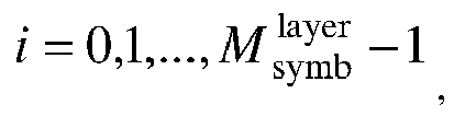


0 ) (i) used during transmission, and so on, receiving a data layer x(v-1)(i) on a DMRS port y (pv-1 )(i) used during transmission. - The apparatus according to claim 22, wherein, when a DMRS configuration type is a first type and a maximum quantity of DMRS symbols is 1, values of {P0, ..., Pv-1} are determined by a following table:
DMRS port(s) {P0, ..., Pv-1} 0 p 0 = 0 1 p 0 = 1 0,1 p 0 = 0 p 1 = 1 2 p 0 = 2 3 p 0 = 3 2,3 p 0 = 2 p 1 = 3 p 0 = 0 p 1 = 1 p 2 = 2 0-2 or p 0 = 2 p 1 = 0 p 2 = 1 p 0 = 0 p 1 = 1 p 2 = 2 p 3 = 3 0-3 or p 0 = 2 p 1 = 3 p 2 = 0 p 3 = 1 p 0 = 0 p 1 = 2 0,2 or p 0 = 2 p 1 = 0 - The apparatus according to claim 22, wherein, when a DMRS configuration type is a first type and a maximum quantity of DMRS symbols is 2, values of {P0, ..., Pv-1} are determined by a following table:
DMRS port(s) {P0, ..., Pv-1 } 0 p 0 = 0 1 p 0 = 1 0,1 p 0 = 0 p 1 = 1 2 p 0 = 2 3 p 0 = 3 2,3 p 0 = 2 p 1 = 3 p 0 = 0 p 1 = 1 p 2 = 2 0-2 or p 0 = 2 p 1 = 0 p 2 = 1 p 0 = 0 p 1 = 1 p 2 = 2 p 3 = 3 0-3 or p 0 = 2 p 1 = 3 p 2 = 0 p 3 = 1 p 0 = 0 p 1 = 2 0,2 or p 0 = 2 p 1 = 0 4 p 0 = 4 5 p 0 = 5 6 p 0 = 6 7 p 0 = 7 4,5 p 0 = 4 p 1 = 5 6,7 p 0 = 6 p 1 = 7 0,4 p 0 = 0 p 1 = 4 2,6 p 0 = 2 p 1 = 6 p 0 = 0 0,1,4 p 1 = 1 p 2 = 4 p 0 = 2 2,3,6 p 1 = 3 p 2 = 6 p 0 = 0 p 1 = 1 0,1,4,5 p 2 = 4 p 3 = 5 p 0 = 2 p 1 = 3 2,3,6,7 p 2 = 6 p 3 = 7 p 0 = 0 p 1 = 2 p 2 = 4 p 3 = 6 or p 0 = 2 p 1 = 6 0,2,4,6 p 2 = 0 p 3 = 4 or p 0 = 0 p 1 = 4 p 2 = 2 p 3 = 6 p 0 = 2 p 1 = 3 p 2 = 0 P3 = 1 P4 = 4 0-4 or p 0 = 0 p 1 = 1 p 2 = 2 p 3 = 3 p 4 = 4 p 0 = 2 p 1 = 3 p 2 = 6 p 3 = 0 p 4 = 1 p 5 = 4 or p 0 = 0 0,1,2,3,4,6 p 1 = 1 p 2 = 4 p 3 = 2 p 4 = 3 p 5 = 6 or p 1 = 1 p 2 = 2 p 3 = 3 p 4 = 4 p 5 = 6 p 0 = 2 p 1 = 3 p 2 = 6 p 3 = 0 p 4 = 1 p 5 = 4 p 6 = 5 0,1,2,3,4,5,6 or p 0 = 0 p 1 = 1 p 2 = 2 p 3 = 3 p 4 = 4 p 5 = 5 p 6 = 6 p 0 = 2 p 1 = 3 p 2 = 6 p 3 = 7 p 4 = 0 p 5 = 1 p 6 = 4 p 7 = 5 or p 0 = 0 p 1 = 1 p 2 = 4 p 3 = 5 0,1,2,3,4,5,6,7 p 4 = 2 p 5 = 3 p 6 = 6 p 7 = 7 or p 0 = 0 p 1 = 1 p 2 = 2 p 3 = 3 p 4 = 4 p 5 = 5 p 6 = 6 p 7 = 7 - The apparatus according to claim 22, wherein, when a DMRS configuration type is a second type and a maximum quantity of DMRS symbols is 1, values of {P0, ..., Pv-1} are determined by a following table:
DMRS port(s) {P0, ..., Pv-1} 0 p 0 = 0 1 p 0 = 1 0,1 p 0 = 0 p 1 = 1 2 p 0 = 2 3 p 0 = 3 2,3 p 0 = 2 p 1 = 3 0-2 p 0 = 0 p 1 = 1 p 2 = 2 or p 0 = 2 p 1 = 0 p 2 = 1 0-3 p 0 = 0 p 1 = 1 p 2 = 2 p 3 = 3 or p 0 = 2 p 1 = 3 p 2 = 0 p 3 = 1 4 p 0 = 4 5 p 0 = 5 4,5 p 0 = 4 p 1 = 5 3-5 p 0 = 3 p 1 = 4 p 2 = 5 or p 0 = 4 p 1 = 5 p 2 = 3 0-3 p 0 = 0 p 1 = 1 p 2 = 2 p 3 = 3 or p 0 = 2 p 1 = 3 p 2 = 0 p 3 = 1 0,2 p 0 = 0 p 1 = 2 or p 0 = 2 p 1 = 0 0-4 p 0 = 0 p 1 = 1 p 2 = 2 p 3 = 3 p 4 = 4 0-5 p 0 = 0 p 1 = 1 p 2 = 2 p 3 = 3 p 4 = 4 p 4 = 5 or p 0 = 0 p 1 = 1 p 2 = 4 p 3 = 5 p 4 = 2 p 4 = 3 or p 0 = 2 p 1 = 3 p 2 = 0 p 3 = 1 p 4 = 4 p 4 = 5 or p 0 = 2 p 1 = 3 p 2 = 4 p 3 = 5 p 4 = 0 p 4 = 1 or p 0 = 4 p 1 = 5 p 2 = 0 p 3 = 1 p 4 = 2 p 4 = 3 or p 0 = 4 p 1 = 5 p 2 = 2 p 3 = 3 p 4 = 0 p 4 = 1 - The apparatus according to claim 22, wherein, when a DMRS configuration type is a second type and a maximum quantity of DMRS symbols is 2, values of {P0, ..., Pv-1} are determined by a following table:
DMRS port(s) {P0, ..., Pv-1} 0 p 0 = 0 1 p 0 = 1 0,1 p 0 = 0 p 1 = 1 2 p 0 = 2 3 p 0 = 3 0,1 p 0 = 0 p 1 = 1 2,3 p 0 = 2 p 1 = 3 0-2 p 0 = 0 p 1 = 1 p 2 = 2 or p 0 = 2 p 1 = 0 p 2 = 1 0-3 p 0 = 0 p 1 = 1 p 2 = 2 p 3 = 3 or p 0 = 2 p 1 = 3 p 2 = 0 p 3 = 1 4 p 0 = 4 5 p 0 = 5 4,5 p 0 = 4 p 1 = 5 3-5 p 0 = 3 p 1 = 4 p 2 = 5 or Po = 5 p 1 = 3 p 2 = 4 0-3 p 0 = 0 p 1 = 1 p 2 = 2 p 3 = 3 or p 0 = 2 p 1 = 3 p 2 = 0 p 3 = 1 0,2 p 0 = 0 p 1 = 2 or p 0 = 2 p 1 = 0 6 p 0 = 6 7 p 0 = 7 8 p 0 = 8 9 p 0 = 9 10 p 0 = 10 11 p 0 = 11 6,7 p 0 = 6 p 1 = 7 8,9 p 0 = 8 p 1 = 9 10,11 p 0 = 10 p 1 = 11 0,1,6 p 0 = 0 p 1 = 1 p 2 = 6 2,3,8 p 0 = 2 p 1 = 3 p 2 = 8 4,5,10 p 0 = 4 p 1 = 5 p 2 = 10 0,1,6,7 p 0 = 0 p 1 = 1 p 2 = 6 p 3 = 7 2,3,8,9 p 0 = 2 p 1 = 3 p 2 = 8 p 3 = 9 4,5,10,11 p 0 = 4 p 1 = 5 p 2 = 10 p 3 = 11 0-4 p 0 = 0 p 1 = 1 p 2 = 2 p 3 = 3 p 4 = 4 p 0 = 0 p 1 = 1 p 2 = 2 p 3 = 3 p 4 = 4 p 4 = 5 or p 0 = 0 p 1 = 1 p 2 = 4 p 3 = 5 p 4 = 2 p 4 = 3 or p 0 = 2 p 1 = 3 p 2 = 0 p 3 = 1 p 4 = 4 0-5 p 4 = 5 or p 0 = 2 p 1 = 3 p 2 = 4 p 3 = 5 p4 = 0 p4 = 1 or p 0 = 4 p 1 = 5 p 2 = 0 p 3 = 1 p 4 = 2 p 4 = 3 or p 0 = 4 p 1 = 5 p 2 = 2 p 3 = 3 p 4 = 0 p 4 = 1 p 0 = 2 p 1 = 3 p 2 = 0 p 3 = 1 p 4 = 6 0,1,2,3,6 or p 0 = 0 p 1 = 1 p 2 = 2 p 3 = 3 p 4 = 6 p 0 = 2 p 1 = 3 p 2 = 8 p 3 = 0 p 4 = 1 p 5 = 6 or p 0 = 0 p 1 = 1 p 2 = 6 0,1,2,3,6,8 p 3 = 2 p 4 = 3 p 5 = 8 or p 0 = 0 p 1 = 1 p 2 = 2 p 3 = 3 p 4 = 6 p 5 = 8 p 0 = 2 p 1 = 3 p 2 = 8 p 3 = 0 p 4 = 1 p 5 = 6 p 6 = 7 0,1,2,3,6,7,8 or p 0 = 0 p 1 = 1 p 2 = 2 p 3 = 3 p 4 = 6 p 5 = 7 p 6 = 8 p 0 = 2 p 1 = 3 p 2 = 8 p 3 = 9 p 4 = 0 p 5 = 1 p 6 = 6 p 7 = 7 or p 0 = 0 p 1 = 1 p 2 = 6 p 3 = 7 0,1,2,3,6,7,8,9 p 4 = 2 p 5 = 3 p 6 = 8 p 7 = 9 or p 0 = 0 p 1 = 1 p 2 = 2 p 3 = 3 p 4 = 6 p 5 = 7 p 6 = 8 p 7 = 9 - The apparatus according to claim 22, wherein, when a DMRS configuration type is a first type and a maximum quantity of DMRS symbols is 1, values of {P0, ..., Pv-1} are determined by a following table:
One Codeword: Codeword 0 enabled, Codeword 1 disabled Value Number of DMRS CDM group(s) without data DMRS port(s) {P0, ..., Pv-1} 0 1 0 p 0 = 0 1 1 1 p 0 = 1 2 1 0,1 p 0 = 0 p 1 = 1 3 2 0 p 0 = 0 4 2 1 p 0 = 1 5 2 2 p 0 = 2 6 2 3 p 0 = 3 7 2 0,1 p 0 = 0 p 1 = 1 8 2 2,3 p 0 = 2 p 1 = 3 9 2 0-2 p 0 = 0 p 1 = 1 p 2 = 2 or p 0 = 2 p 1 = 0 p 2 = 1 10 2 0-3 p 0 = 0 p 1 = 1 p 2 = 2 p 3 = 3 or p 0 = 2 p 1 = 3 p 2 = 0 p 3 = 1 11 2 0,2 p 0 = 0 p 1 = 2 or p 0 = 2 p 1 = 0 12-15 Reserved Reserved - The apparatus according to claim 22, wherein, when a DMRS configuration type is a first type and a maximum quantity of DMRS symbols is 2, values of {P0, ..., Pv-1} are determined by a following table:
One Codeword: Two Codewords: Codeword 0 enabled, Codeword 0 enabled, Codeword 1 disabled Codeword 1 enabled Value Number of DMRS CDM group(s) without data DMRS port(s) {P0, ..., Pv- 1} Number of front-load symbols Value Number of DMRS CDM group(s) without data DMRS port(s) {P0, ..., Pv-1} Number of front-load symbols p 0 = 2 p 1 = 3 p 2 = 0 p 3 = 1 p 4 = 4 0 1 0 p 0 = 0 1 0 2 0-4 or 2 p 0 = 0 p 1 = 1 p 2 = 2 p 3 = 3 p 4 = 4 p 0 = 2 p 1 = 3 p 2 = 6 p 3 = 0 p 4 = 1 p 5 = 4 or p 0 = 0 p 1 = 1 1 1 1 p 0 = 1 1 1 2 0,1,2,3,4,6 p 2 = 4 2 p 3 = 2 p 4 = 3 p 5 = 6 or p 0 = 0 p 1 = 1 p 2 = 2 p 3 = 3 p 4 = 4 p 5 = 6 p 0 = 2 p 1 = 3 p 2 = 6 p 3 = 0 p 4 = 1 p 5 = 4 2 1 0,1 p 0 = 0 1 2 2 0,1,2,3,4,5,6 p 6 = 5 2 p 1 = 1 p 0 = 0 p 1 = 1 p 2 = 2 p 3 = 3 p 4 = 4 p 5 = 5 p 6 = 6 p 0 = 2 p 1 = 3 p 2 = 6 p 3 = 7 p 4 = 0 p 5 = 1 p 6 = 4 p 7 = 5 or p 0 = 0 p 1 = 1 p 2 = 4 3 2 0 p 0 = 0 1 3 2 0,1,2,3,4,5,6,7 p 3 = 5 2 p 4 = 2 p 5 = 3 p 6 = 6 p 7 = 7 or p 0 = 0 p 1 = 1 p 2 = 2 p 3 = 3 p 4 = 4 p 5 = 5 p 6 = 6 p 7 = 7 4 2 1 p 0 = 1 1 4-31 reserved reserved reserved 5 2 2 p 0 = 2 1 6 2 3 p 0 = 3 1 7 2 0,1 p 0 = 0 1 p 1 = 1 8 2 2,3 p 0 = 2 1 p 1 = 3 p 0 = 0 p 1 = 1 p 2 = 2 9 2 0-2 or 1 p 0 = 2 p 1 = 0 p 2 = 1 Po = 0 p 1 = 1 p 2 = 2 p 3 = 3 10 2 0-3 or 1 p 0 = 2 p 1 = 3 p 2 = 0 p 3 = 1 p 0 = 0 p 1 = 2 11 2 0,2 or 1 p 0 = 2 p 1 = 0 12 2 0 p 0 = 0 2 13 2 1 p 0 = 1 2 14 2 2 p 0 = 2 2 15 2 3 p 0 = 3 2 16 2 4 p 0 = 4 2 17 2 5 p 0 = 5 2 18 2 6 p 0 = 6 2 19 2 7 p 0 = 7 2 20 2 0,1 p 0 = 0 2 p 1 = 1 21 2 2,3 p 0 = 2 2 p 1 = 3 22 2 4,5 p 0 = 4 2 p 1 = 5 23 2 6,7 p 0 = 6 2 p 1 = 7 24 2 0,4 p 0 = 0 2 p 1 = 4 25 2 2,6 p 0 = 2 2 p 1 = 6 p 0 = 0 26 2 0,1,4 p 1 = 1 2 p 2 = 4 p 0 = 2 27 2 2,3,6 p 1 = 3 2 p 2 = 6 p 0 = 0 28 2 0,1,4,5 p 1 = 1 2 p 2 = 4 p 3 = 5 p 0 = 2 29 2 2,3,6,7 p 1 = 3 2 p 2 = 6 p 3 = 7 p 0 = 0 p 1 = 2 p 2 = 4 p 3 = 6 or p 0 = 2 30 2 0,2,4,6 p 1 = 6 2 p 2 = 0 p 3 = 4 or p 0 = 0 p 1 = 4 p 2 = 2 p 3 = 6 31 Reserved Reserved Reserved - The apparatus according to claim 22, wherein, when a DMRS configuration type is a second type and a maximum quantity of DMRS symbols is 1, values of {P0, ..., Pv-1} are determined by a following table:
One codeword: Two codewords: Codeword 0 enabled, Codeword 0 enabled, Codeword 1 disabled Codeword 1 enabled Value Number of DMRS CDM group(s) without data DMRS port(s) {P0, ..., Pv-1} Value Number of DMRS CDM group(s) without data DMRS port(s) {P0, ..., Pv-1} p 0 = 0 p 1 = 1 0 1 0 p 0 = 0 0 3 0-4 p 2 = 2 p 3 = 3 p 4 = 4 p 0 = 0 p 1 = 1 p 2 = 2 p 3 = 3 p 4 = 4 p 4 = 5 or p 0 = 0 p 1 = 1 p 2 = 4 p 3 = 5 p 4 = 2 p 4 = 3 or p 0 = 2 p 1 = 3 p 2 = 0 p 3 = 1 p 4 = 4 p 4 = 5 1 1 1 p 0 = 1 1 3 0-5 or p 0 = 2 p 1 = 3 p 2 = 4 p 3 = 5 p 4 = 0 p 4 = 1 or p 0 = 4 p 1 = 5 p 2 = 0 p 3 = 1 p 4 = 2 p 4 = 3 or p 0 = 4 p 1 = 5 p 2 = 2 p 3 = 3 p 4 = 0 p 4 = 1 2 1 0,1 p 0 = 0 2-31 reserved reserved p 1 = 1 3 2 0 p 0 = 0 4 2 1 p 0 = 1 5 2 2 p 0 = 2 6 2 3 p 0 = 3 7 2 0,1 p 0 = 0 p 1 = 1 8 2 2,3 p 0 = 2 p 1 = 3 p 0 = 0 p 1 = 1 p 2 = 2 9 2 0-2 or p 0 = 2 p 1 = 0 p 2 = 1 p 0 = 0 p 1 = 1 p 2 = 2 p 3 = 3 10 2 0-3 or p 0 = 2 p 1 = 3 p 2 = 0 p 3 = 1 11 3 0 p 0 = 0 12 3 1 p 0 = 1 13 3 2 p 0 = 2 14 3 3 p 0 = 3 15 3 4 p 0 = 4 16 3 5 p 0 = 5 17 3 0,1 p 0 = 0 p 1 = 1 18 3 2,3 p 0 = 2 p 1 = 3 19 3 4,5 p 0 = 4 p 1 = 5 p 0 = 0 p 1 = 1 p 2 = 2 20 3 0-2 or p 0 = 2 p 1 = 0 p 2 = 1 p 0 = 3 p 1 = 4 p 2 = 5 21 3 3-5 or p 0 = 4 p 1 = 5 p 2 = 3 p 0 = 0 p 1 = 1 p 2 = 2 p 3 = 3 22 3 0-3 or p 0 = 2 p 1 = 3 p 2 = 0 p 3 = 1 p 0 = 0 p 1 = 2 23 2 0,2 or p 0 = 2 p 1 = 0 24-31 Reserved Reserved - The apparatus according to claim 22, wherein, when a DMRS configuration type is a second type and a maximum quantity of DMRS symbols is 2, values of {P0, ..., Pv-1} are determined by a following table:
One codeword: Two Codewords: Codeword 0 enabled, Codeword 0 enabled, Codeword 1 disabled Codeword 1 enabled Value Number of DMRS CDM group(s) without data DMRS port(s) {P0, ..., Pv-1} Number of front-load symbols Value Number of DMRS CDM group(s) without data DMRS port(s) {P0, ..., Pv-1} Number of front-load symbols p 0 = 0 p 1 = 1 0 1 0 p 0 = 0 1 0 3 0-4 p 2 = 2 1 p 3 = 3 p 4 = 4 p 0 = 0 p 1 = 1 p 2 = 2 p 3 = 3 p 4 = 4 p 4 = 5 or p 0 = 0 p 1 = 1 p 2 = 4 p 3 = 5 p 4 = 2 p 4 = 3 or p 0 = 2 p 1 = 3 p 2 = 0 p 3 = 1 p 4 = 4 p 4 = 5 1 1 1 p 0 = 1 1 1 3 0-5 or 1 p 0 = 2 p 1 = 3 p 2 = 4 p 3 = 5 p 4 = 0 p 4 = 1 or p 0 = 4 p 1 = 5 p 2 = 0 p 3 = 1 p 4 = 2 p 4 = 3 or p 0 = 4 p 1 = 5 p 2 = 2 p 3 = 3 p 4 = 0 p 4 = 1 2 1 0,1 1 2 2 0,1,2,3,6 p 0 = 2 2 p 1 = 3 p 2 = 0 p 3 = 1 p 4 = 6 p 0 = 0 or p 1 = 1 p 0 = 0 p 1 = 1 p 2 = 2 p 3 = 3 p 4 = 6 p 0 = 2 p 1 = 3 p 2 = 8 p 3 = 0 p 4 = 1 p 5 = 6 or p 0 = 0 p 1 = 1 p 2 = 6 3 2 0 p 0 = 0 1 3 2 0,1,2,3,6,8 p 3 = 2 2 p 4 = 3 p 5 = 8 or p 0 = 0 p 1 = 1 p 2 = 2 p 3 = 3 p 4 = 6 p 5 = 8 p 0 = 2 p 1 = 3 p 2 = 8 p 3 = 0 p 4 = 1 p 5 = 6 0,1,2,3,6,7,8 p 6 = 7 4 2 1 p 0 = 1 1 4 2 or 2 p 0 = 0 p 1 = 1 p 2 = 2 p 3 = 3 p 4 = 6 p 5 = 7 p 6 = 8 p 0 = 2 p 1 = 3 p 2 = 8 p 3 = 9 P4 = 0 p 5 = 1 p 6 = 6 p 7 = 7 or p 0 = 0 p 1 = 1 p 2 = 6 5 2 2 p 0 = 2 1 5 2 0,1,2,3,6,7,8,9 p 3 = 7 2 p 4 = 2 p 5 = 3 p 6 = 8 p 7 = 9 or p 0 = 0 p 1 = 1 p 2 = 2 p 3 = 3 p 4 = 6 p 5 = 7 p 6 = 8 p 7 = 9 6 2 3 p 0 = 3 1 6-63 Reserved Reserved Reserved 7 2 0,1 p 0 = 0 1 p 1 = 1 8 2 2,3 p 0 = 2 1 p 1 = 3 p 0 = 0 p 1 = 1 p 2 = 2 9 2 0-2 or 1 p 0 = 2 p 1 = 0 p 2 = 1 p 0 = 0 p 1 = 1 p 2 = 2 p 3 = 3 10 2 0-3 or 1 p 0 = 2 p 1 = 3 p 2 = 0 p 3 = 1 11 3 0 p 0 = 0 1 12 3 1 p 0 = 1 1 13 3 2 p 0 = 2 1 14 3 3 p 0 = 3 1 15 3 4 p 0 = 4 1 16 3 5 p 0 = 5 1 17 3 0,1 p 0 = 0 1 p 1 = 1 18 3 2,3 p 0 = 2 1 p 1 = 3 19 3 4,5 p 0 = 4 1 p 1 = 5 p 0 = 0 p 1 = 1 p 2 = 2 20 3 0-2 or 1 p 0 = 2 p 1 = 0 p 2 = 1 p 0 = 3 p 1 = 4 p 2 = 5 21 3 3-5 or 1 p 0 = 5 p 1 = 3 p 2 = 4 p 0 = 0 p 1 = 1 p 2 = 2 p 3 = 3 22 3 0-3 or 1 p 0 = 2 p 1 = 3 p 2 = 0 p 3 = 1 p 0 = 0 p 1 = 2 23 2 0,2 or 1 p 0 = 2 p 1 = 0 24 3 0 p 0 = 0 2 25 3 1 p 0 = 1 2 26 3 2 p 0 = 2 2 27 3 3 p 0 = 3 2 28 3 4 p 0 = 4 2 29 3 5 p 0 = 5 2 30 3 6 p 0 = 6 2 31 3 7 p 0 = 7 2 32 3 8 p 0 = 8 2 33 3 9 p 0 = 9 2 34 3 10 p 0 = 10 2 35 3 11 p 0 = 11 2 36 3 0,1 p 0 = 0 2 p 1 = 1 37 3 2,3 p 0 = 2 2 p 1 = 3 38 3 4,5 p 0 = 4 2 p 1 = 5 39 3 6,7 p 0 = 6 2 p 1 = 7 40 3 8,9 p 0 = 8 2 p 1 = 9 41 3 10,11 p 0 = 10 2 p 1 = 11 42 3 0,1,6 p 0 = 0 2 p 1 = 1 p 2 =6 p 0 = 2 43 3 2,3,8 p 1 = 3 2 p 2 = 8 p 0 = 4 44 3 4,5,10 p 1 = 5 2 p 2 = 10 p 0 = 0 45 3 0,1,6,7 p 1 = 1 2 p 2 = 6 p 3 = 7 p 0 = 2 46 3 2,3,8,9 p 1 = 3 2 p 2 = 8 p 3 = 9 p 0 = 4 47 3 4,5,10,11 p 1 = 5 p 2 = 10 2 p 3 = 11 48 1 0 p 0 = 0 2 49 1 1 p 0 = 1 2 50 1 6 p 0 = 6 2 51 1 7 p 0 = 7 2 52 1 0,1 p 0 = 0 2 p 1 = 1 53 1 6,7 p 0 = 6 2 p 1 = 7 54 2 0,1 p 0 = 0 2 p 1 = 1 55 2 2,3 p 0 = 2 2 p 1 = 3 56 2 6,7 p 0 = 6 2 p 1 = 7 57 2 8,9 p 0 = 8 2 p 1 = 9 58-63 Reserved Reserved Reserved - The apparatus according to claim 22, wherein, when a DMRS configuration type is a first type and a maximum quantity of DMRS symbols is 1, values of {P0, ..., Pv-1} are determined by a following table:
One Codeword: Codeword 0 enabled, Codeword 1 disabled Value Number of DMRS CDM group(s) without data {P0, ..., Pv-1} 0 1 p 0 = 0 1 1 p 0 = 1 2 1 p 0 = 0 p 1 = 1 3 2 p 0 = 0 4 2 p 0 = 1 5 2 p 0 = 2 6 2 p 0 = 3 7 2 p 0 = 0 p 1 = 1 8 2 p 0 = 2 p 1 = 3 p 0 = 0 p 1 = 1 p 2 = 2 9 2 or p 0 = 2 p 1 = 0 p 2 = 1 p 0 = 0 p 1 = 1 p 2 = 2 p 3 = 3 10 2 or p 0 = 2 p 1 = 3 p 2 = 0 p 3 = 1 p 0 = 0 p 1 = 2 11 2 or p 0 = 2 p 1 = 0 12-15 Reserved - The apparatus according to claim 22, wherein, when a DMRS configuration type is a first type and a maximum quantity of DMRS symbols is 2 values of {P0, ..., Pv-1} are determined by a following table:
One Codeword: Two Codewords: Codeword 0 enabled, Codeword 0 enabled, Codeword 1 disabled Codeword 1 enabled Value Number of DMRS CDM group(s) without data {P0, ..., Pv-1} Number of front-load symbols Value Number of DMRS CDM group(s) without data {P0, ..., Pv-1} Number of front-load symbols p 0 = 2 p 1 = 3 p 2 = 0 p 3 = 1 p 4 = 4 0 1 p 0 = 0 1 0 2 or 2 p 0 = 0 p 1 = 1 p 2 = 2 p 3 = 3 p 4 = 4 p 0 = 2 p 1 = 3 p 2 = 6 p 3 = 0 p 4 = 1 p 5 = 4 or p 0 = 0 p 1 = 1 p 2 = 4 1 1 p 0 = 1 1 1 2 p 3 = 2 2 p 4 = 3 p 5 = 6 or p 0 = 0 p 1 = 1 p 2 = 2 p 3 = 3 p 4 = 4 p 5 = 6 p 0 = 2 p 1 = 3 p 2 = 6 p 3 = 0 p 4 = 1 p 5 = 4 2 1 p 0 = 0 1 2 2 p 6 = 5 2 or p 1 = 1 p 0 = 0 p 1 = 1 p 2 = 2 p 3 = 3 p 4 = 4 p 5 = 5 p 6 = 6 p 0 = 2 p 1 = 3 p 2 = 6 p 3 = 7 p 4 = 0 p 5 = 1 p 6 = 4 p 7 = 5 or p 0 = 0 p 1 = 1 p 2 = 4 3 2 p 0 = 0 1 3 2 p 3 = 5 2 p 4 = 2 p 5 = 3 p 6 = 6 p 7 = 7 or p 0 = 0 p 1 = 1 p 2 = 2 p 3 = 3 p 4 = 4 p 5 = 5 p 6 = 6 p 7 = 7 4 2 p 0 = 1 1 4-31 reserved reserved 5 2 p 0 = 2 1 6 2 p 0 = 3 1 7 2 p 0 = 0 1 p 1 = 1 8 2 p 0 = 2 1 p 1 = 3 p 0 = 0 p 1 = 1 p 2 = 2 9 2 or 1 p 0 = 2 p 1 = 0 p 2 = 1 10 2 p 0 = 0 1 p 1 = 1 p 2 = 2 p 3 = 3 or p 0 = 2 p 1 = 3 p 2 = 0 p 3 = 1 p 0 = 0 p 1 = 2 11 2 or 1 p 0 = 2 p 1 = 0 12 2 p 0 = 0 2 13 2 p 0 = 1 2 14 2 p 0 = 2 2 15 2 p 0 = 3 2 16 2 p 0 = 4 2 17 2 p 0 = 5 2 18 2 p 0 = 6 2 19 2 p 0 = 7 2 20 2 p 0 = 0 2 p 1 = 1 21 2 p 0 = 2 2 p 1 = 3 22 2 p 0 = 4 2 p 1 = 5 23 2 p 0 = 6 2 p 1 = 7 24 2 p 0 = 0 2 p 1 = 4 25 2 p 0 = 2 2 p 1 = 6 p 0 = 0 26 2 p 1 = 1 2 p 2 = 4 p 0 = 2 27 2 p 1 = 3 2 p 2 = 6 p 0 = 0 28 2 p 1 = 1 2 p 2 = 4 p3 = 5 p 0 = 2 29 2 p 1 = 3 2 p 2 = 6 p 3 = 7 p 0 = 0 p 1 = 2 p 2 = 4 p 3 = 6 or p 0 = 2 30 2 p 1 = 6 2 p 2 = 0 p 3 = 4 or p 0 = 0 p 1 = 4 p 2 = 2 p 3 = 6 31 Reserved Reserved - The apparatus according to claim 22, wherein, when a DMRS configuration type is a second type and a maximum quantity of DMRS symbols is 1, values of {P0, ..., Pv-1} are determined by a following table:
One Codeword: Two Codewords: Codeword 0 enabled, Codeword 0 enabled, Codeword 1 disabled Codeword 1 enabled Value Number of DMRS CDM group(s) without data {P0, ..., Pv-1} Value Number of DMRS CDM group(s) without data {P0, ..., Pv- 1} 0 1 p 0 = 0 0 3 p 0 = 0 p 1 = 1 p 2 = 2 p 3 = 3 p 4 = 4 p 0 = 0 p 1 = 1 p 2 = 2 p 3 = 3 p 4 = 4 p 4 = 5 or p 0 = 0 p 1 = 1 p 2 = 4 p 3 = 5 p 4 = 2 p 4 = 3 or p 0 = 2 p 1 = 3 p 2 = 0 P3 = 1 p 4 = 4 p 4 = 5 1 1 p 0 = 1 1 3 or p 0 = 2 p 1 = 3 p 2 = 4 p 3 = 5 P4 = 0 P4 = 1 or p 0 = 4 p 1 = 5 p 2 = 0 P3 = 1 P4 = 2 p 4 = 3 or p 0 = 4 p 1 = 5 p 2 = 2 p 3 = 3 P4 = 0 p 4 = 1 2 1 p 0 = 0 2-31 reserved p 1 = 1 3 2 p 0 = 0 4 2 p 0 = 1 5 2 p 0 = 2 6 2 p 0 = 3 7 2 p 0 = 0 p 1 = 1 8 2 p 0 = 2 p 1 = 3 9 2 p 0 = 0 p 1 = 1 p 2 = 2 or p 0 = 2 p 1 = 0 p 2 = 1 10 2 p 0 = 0 p 1 = 1 p 2 = 2 p 3 = 3 or p 0 = 2 p 1 = 3 p 2 = 0 p 3 = 1 11 3 p 0 = 0 12 3 p 0 = 1 13 3 p 0 = 2 14 3 p 0 = 3 15 3 p 0 = 4 16 3 p 0 = 5 17 3 p 0 = 0 p 1 = 1 18 3 p 0 = 2 p 1 = 3 19 3 p 0 = 4 p 1 = 5 20 3 p 0 = 0 p 1 = 1 p 2 = 2 or p 0 = 2 p 1 = 0 p 2 = 1 21 3 p 0 = 3 p 1 = 4 p 2 = 5 or p 0 = 4 p 1 = 5 p 2 = 3 22 3 p 0 = 0 p 1 = 1 p 2 = 2 p 3 = 3 or p 0 = 2 p 1 = 3 p 2 = 0 p 3 = 1 23 2 p 0 = 0 p 1 = 2 or p 0 = 2 p 1 = 0 24-31 Reserved - The apparatus according to claim 22, wherein, when a DMRS configuration type is a second type and a maximum quantity of DMRS symbols is 2, values of {P0, ..., Pv-1} are determined by a following table:
One Codeword: Two Codewords: Codeword 0 enabled, Codeword 0 enabled, Codeword 1 disabled Codeword 1 enabled Value Number of DMRS CDM group(s) without data {P0, ..., Pv-1} Number of front-load symbols Value Number of DMRS CDM group(s) without data {P0, ..., Pv-1} Number of front-load symbols 0 1 p 0 = 0 1 0 3 p 0 = 0 1 p 1 = 1 p 2 = 2 p 3 = 3 p 4 = 4 p 0 = 0 p 1 = 1 p 2 = 2 p 3 = 3 p 4 = 4 p 4 = 5 or p 0 = 0 p 1 = 1 p 2 = 4 p 3 = 5 p 4 = 2 p 4 = 3 or p 0 = 2 p 1 = 3 p 2 = 0 p 3 = 1 p 4 = 4 p 4 = 5 1 1 p 0 = 1 1 1 3 or 1 p 0 = 2 p 1 = 3 p 2 = 4 p 3 = 5 p 4 = 0 p 4 = 1 or p 0 = 4 p 1 = 5 p 2 = 0 p 3 = 1 p 4 = 2 p 4 = 3 or p 0 = 4 p 1 = 5 p 2 = 2 p 3 = 3 p 4 = 0 p 4 = 1 2 1 1 2 2 p 0 = 2 2 p 1 = 3 p 2 = 0 p 3 = 1 p 0 = 0 p 4 = 6 p 1 = 1 or p 0 = 0 p 1 = 1 p 2 = 2 p 3 = 3 p 4 = 6 p 0 = 2 p 1 = 3 p 2 = 8 p 3 = 0 p 4 = 1 p 5 = 6 or p 0 = 0 p 1 = 1 p 2 = 6 3 2 p 0 = 0 1 3 2 p 3 = 2 2 p 4 = 3 p 5 = 8 or p 0 = 0 p 1 = 1 p 2 = 2 p 3 = 3 p 4 = 6 p 5 = 8 4 2 p 0 = 1 1 4 2 p 0 = 2 2 p 1 = 3 p 2 = 8 p 3 = 0 p 4 = 1 p 5 = 6 p 6 = 7 or p 0 = 0 p 1 = 1 p 2 = 2 p 3 = 3 p 4 = 6 p 5 = 7 p 6 = 8 p 0 = 2 p 1 = 3 p 2 = 8 p 3 = 9 p 4 = 0 p 5 = 1 p 6 = 6 p 7 = 7 or p 0 = 0 p 1 = 1 p 2 = 6 p 3 = 7 5 2 p 0 = 2 1 5 2 p 4 = 2 2 p 5 = 3 p 6 = 8 p 7 = 9 or p 0 = 0 p 1 = 1 p 2 = 2 p 3 = 3 p 4 = 6 p 5 = 7 p 6 = 8 p 7 = 9 6 2 p 0 = 3 1 6-63 Reserved Reserved 7 2 p 0 = 0 1 p 1 = 1 8 2 p 0 = 2 1 p 1 = 3 9 2 p 0 = 0 1 p 1 = 1 p 2 = 2 or p 0 = 2 p 1 = 0 p 2 = 1 10 2 p 0 = 0 1 p 1 = 1 p 2 = 2 p 3 = 3 or p 0 = 2 p 1 = 3 p 2 = 0 p 3 = 1 11 3 p 0 = 0 1 12 3 p 0 = 1 1 13 3 p 0 = 2 1 14 3 p 0 = 3 1 15 3 p 0 = 4 1 16 3 p 0 = 5 1 17 3 p 0 = 0 1 p 1 = 1 18 3 p 0 = 2 1 p 1 = 3 19 3 p 0 = 4 1 p 1 = 5 20 3 p 0 = 0 1 p 1 = 1 p 2 = 2 or p 0 = 2 p 1 = 0 p 2 = 1 21 3 p 0 = 3 1 p 1 = 4 p 2 = 5 or p 0 = 5 p 1 = 3 p 2 = 4 22 3 p 0 = 0 1 p 1 = 1 p 2 = 2 p 3 = 3 or p 0 = 2 p 1 = 3 p 2 = 0 p 1 = 1 23 2 p 0 = 0 1 p 1 = 2 or p 0 = 2 p 1 = 0 24 3 p 0 = 0 2 25 3 p 0 = 1 2 26 3 p 0 = 2 2 27 3 p 0 = 3 2 28 3 p 0 = 4 2 29 3 p 0 = 5 2 30 3 p 0 = 6 2 31 3 p 0 = 7 2 32 3 p 0 = 8 2 33 3 p 0 = 9 2 34 3 p 0 = 10 2 35 3 p 0 = 11 2 36 3 p 0 = 0 2 p 1 = 1 37 3 p 0 = 2 2 p 1 = 3 38 3 p 0 = 4 2 p 1 = 5 39 3 p 0 = 6 2 p 1 = 7 40 3 p 0 = 8 2 p 1 = 9 41 3 p0 = 10 2 p 1 = 11 42 3 Po = 0 2 p 1 = 1 p 2 = 6 43 3 p 0 = 2 2 p 1 = 3 p 2 = 8 44 3 p 0 = 4 2 p 1 = 5 p 2 = 10 45 3 p 0 = 0 2 p 1 = 1 p 2 = 6 p 3 = 7 46 3 p 0 = 2 2 p 1 = 3 p 2 = 8 p 3 = 9 47 3 p 0 = 4 2 p 1 = 5 p 2 = 10 p 3 = 11 48 1 p 0 = 0 2 49 1 p 0 = 1 2 50 1 p 0 = 6 2 51 1 p 0 = 7 2 52 1 p 0 = 0 2 p 1 = 1 53 1 p 0 = 6 2 p 1 = 7 54 2 p 0 = 0 2 p 1 = 1 55 2 p 0 = 2 2 p 1 = 3 56 2 p 0 = 6 2 p 1 = 7 57 2 p 0 = 8 2 p 1 = 9 58-63 Reserved Reserved - An apparatus for sending data, comprising:a determining unit configured to determine a preset Demodulation Reference Signal, DMRS, port ordering rule; anda sending unit configured to map a data layer onto a DMRS port for transmission according to the preset DMRS port ordering rule, and send the data layer to a terminal.
- An apparatus for receiving data, comprising:a determining unit configured to determine a preset Demodulation Reference Signal, DMRS, port ordering rule; anda receiving unit configured to receive a data layer mapped onto a DMRS port according to the preset DMRS port ordering rule.
- A computer storage medium, wherein, the computer storage medium stores computer executable instructions which are configured to cause the computer to perform the method of any one of claims 1-17.
Applications Claiming Priority (2)
| Application Number | Priority Date | Filing Date | Title |
|---|---|---|---|
| CN201810032484.6A CN110034890B (en) | 2018-01-12 | 2018-01-12 | Data transmission method and device and computer storage medium |
| PCT/CN2018/120742 WO2019137144A1 (en) | 2018-01-12 | 2018-12-12 | Data transmission method and apparatus and computer storage medium |
Publications (3)
| Publication Number | Publication Date |
|---|---|
| EP3739792A1 true EP3739792A1 (en) | 2020-11-18 |
| EP3739792A4 EP3739792A4 (en) | 2021-03-03 |
| EP3739792B1 EP3739792B1 (en) | 2024-02-07 |
Family
ID=67218468
Family Applications (1)
| Application Number | Title | Priority Date | Filing Date |
|---|---|---|---|
| EP18900482.3A Active EP3739792B1 (en) | 2018-01-12 | 2018-12-12 | Data transmission method and apparatus and computer storage medium |
Country Status (7)
| Country | Link |
|---|---|
| US (1) | US11405157B2 (en) |
| EP (1) | EP3739792B1 (en) |
| JP (1) | JP2021510284A (en) |
| KR (1) | KR102454234B1 (en) |
| CN (1) | CN110034890B (en) |
| TW (1) | TWI744585B (en) |
| WO (1) | WO2019137144A1 (en) |
Families Citing this family (3)
| Publication number | Priority date | Publication date | Assignee | Title |
|---|---|---|---|---|
| CN114826527A (en) | 2019-07-30 | 2022-07-29 | 华为技术有限公司 | DMRS port indication method and device |
| CN114513236B (en) * | 2020-11-16 | 2023-10-27 | 中国移动通信有限公司研究院 | Multi-antenna precoding method, device and equipment |
| JP7838001B2 (en) * | 2022-01-28 | 2026-03-31 | 中興通訊股▲ふん▼有限公司 | Systems and methods for reference signaling for wireless communication |
Family Cites Families (16)
| Publication number | Priority date | Publication date | Assignee | Title |
|---|---|---|---|---|
| CN101605375B (en) | 2008-06-11 | 2011-02-09 | 大唐移动通信设备有限公司 | Method for sending signalings on downlink control channel |
| RU2548899C2 (en) * | 2010-01-20 | 2015-04-20 | Телефонактиеболагет Лм Эрикссон (Пабл) | Antenna port mapping method and device for demodulating reference signals |
| CN102088429B (en) * | 2010-02-11 | 2013-09-18 | 电信科学技术研究院 | Method and device for mapping demodulation reference symbol port |
| EP2369776B1 (en) | 2010-02-11 | 2018-08-15 | Samsung Electronics Co., Ltd. | Method for indicating a DM-RS antenna port in a wireless communication system |
| CN102158319B (en) * | 2010-02-12 | 2015-12-16 | 中兴通讯股份有限公司 | A kind of method for precoding based on hybrid multiplex demodulation reference mark and device |
| CN102299769B (en) * | 2011-09-01 | 2014-06-25 | 电信科学技术研究院 | Downlink control information transmission method and device |
| JP6307434B2 (en) * | 2011-11-16 | 2018-04-04 | サムスン エレクトロニクス カンパニー リミテッド | Method and apparatus for transmitting control information in a wireless communication system |
| CN103916349B (en) * | 2012-12-31 | 2018-03-23 | 中国移动通信集团公司 | Strengthen the collocation method and device of the demodulation reference mark of public search space |
| US10469222B2 (en) * | 2014-12-16 | 2019-11-05 | Lg Electronics Inc. | Method and MTC device for transmitting DMRS for uplink data demodulation |
| JP6027637B2 (en) * | 2015-01-22 | 2016-11-16 | テレフオンアクチーボラゲット エルエム エリクソン(パブル) | Antenna port mapping method and apparatus for demodulated reference signal |
| CN106162890B (en) * | 2015-04-14 | 2020-02-18 | 中国移动通信集团公司 | A kind of indication method, apparatus and base station of demodulation reference signal DMRS port |
| CN107306177B (en) * | 2016-04-22 | 2023-11-10 | 华为技术有限公司 | Methods of transmitting data, user equipment and network side equipment |
| US20180026764A1 (en) * | 2016-07-25 | 2018-01-25 | Qualcomm Incorporated | Method of mapping transmission layers to frequency division multiplexed demodulation reference signal ports |
| GB201809007D0 (en) | 2018-06-01 | 2018-07-18 | Smith & Nephew | Restriction of sensor-monitored region for sensor-enabled wound dressings |
| CN109391413B (en) * | 2017-08-10 | 2022-05-10 | 华为技术有限公司 | Method and communication device for information transmission |
| CN109842468B (en) * | 2017-11-24 | 2020-09-01 | 电信科学技术研究院 | Data transmission method and device and computer storage medium |
-
2018
- 2018-01-12 CN CN201810032484.6A patent/CN110034890B/en active Active
- 2018-12-12 US US16/961,687 patent/US11405157B2/en active Active
- 2018-12-12 WO PCT/CN2018/120742 patent/WO2019137144A1/en not_active Ceased
- 2018-12-12 KR KR1020207023215A patent/KR102454234B1/en active Active
- 2018-12-12 EP EP18900482.3A patent/EP3739792B1/en active Active
- 2018-12-12 JP JP2020538845A patent/JP2021510284A/en active Pending
- 2018-12-25 TW TW107146910A patent/TWI744585B/en active
Also Published As
| Publication number | Publication date |
|---|---|
| CN110034890A (en) | 2019-07-19 |
| JP2021510284A (en) | 2021-04-15 |
| US20210083826A1 (en) | 2021-03-18 |
| KR20200108045A (en) | 2020-09-16 |
| TWI744585B (en) | 2021-11-01 |
| TW201931809A (en) | 2019-08-01 |
| CN110034890B (en) | 2020-07-10 |
| KR102454234B1 (en) | 2022-10-14 |
| US11405157B2 (en) | 2022-08-02 |
| EP3739792B1 (en) | 2024-02-07 |
| EP3739792A4 (en) | 2021-03-03 |
| WO2019137144A1 (en) | 2019-07-18 |
Similar Documents
| Publication | Publication Date | Title |
|---|---|---|
| KR102290920B1 (en) | DMRS transmission method and communication device | |
| EP3512147B1 (en) | Method and device for transmitting phase tracking reference signal | |
| EP3905578B1 (en) | Method and apparatus for transmitting reference signal, and method and apparatus for receiving reference signal | |
| EP3716708B1 (en) | Data transmission method and apparatus, and computer storage medium | |
| CN109039566B (en) | Method and communication device for transmitting DMRS | |
| EP3855644A1 (en) | Data transmission method, user equipment, and network side device | |
| CN108809572A (en) | Communication method and communication device | |
| KR20190102256A (en) | Data transmission method, terminal device and network device | |
| CN112425228A (en) | Method and apparatus for resource indication | |
| EP3713339A1 (en) | Method and device for information indication and resource determination and computer storage medium | |
| EP3573274B1 (en) | Communication method and network device | |
| EP3099128A1 (en) | Pilot signal transmission method and device | |
| EP3739792B1 (en) | Data transmission method and apparatus and computer storage medium | |
| US11342966B2 (en) | Information indicating and determining method and apparatus, and computer storage medium | |
| EP3373674B1 (en) | Data processing method and apparatus | |
| CN114868445B (en) | Method for reference signal configuration | |
| CN109842469B (en) | Information indication, determination method and device, computer storage medium | |
| WO2015176758A1 (en) | Codeword based discovery scheduling in a device to device communication system | |
| EP4007345A1 (en) | Resource determination method and device | |
| CN115942479A (en) | Data transmission method and related device |
Legal Events
| Date | Code | Title | Description |
|---|---|---|---|
| STAA | Information on the status of an ep patent application or granted ep patent |
Free format text: STATUS: THE INTERNATIONAL PUBLICATION HAS BEEN MADE |
|
| PUAI | Public reference made under article 153(3) epc to a published international application that has entered the european phase |
Free format text: ORIGINAL CODE: 0009012 |
|
| STAA | Information on the status of an ep patent application or granted ep patent |
Free format text: STATUS: REQUEST FOR EXAMINATION WAS MADE |
|
| 17P | Request for examination filed |
Effective date: 20200723 |
|
| AK | Designated contracting states |
Kind code of ref document: A1 Designated state(s): AL AT BE BG CH CY CZ DE DK EE ES FI FR GB GR HR HU IE IS IT LI LT LU LV MC MK MT NL NO PL PT RO RS SE SI SK SM TR |
|
| AX | Request for extension of the european patent |
Extension state: BA ME |
|
| A4 | Supplementary search report drawn up and despatched |
Effective date: 20210203 |
|
| RIC1 | Information provided on ipc code assigned before grant |
Ipc: H04L 5/00 20060101AFI20210128BHEP |
|
| DAV | Request for validation of the european patent (deleted) | ||
| DAX | Request for extension of the european patent (deleted) | ||
| STAA | Information on the status of an ep patent application or granted ep patent |
Free format text: STATUS: EXAMINATION IS IN PROGRESS |
|
| RAP1 | Party data changed (applicant data changed or rights of an application transferred) |
Owner name: DATANG MOBILE COMMUNICATIONS EQUIPMENT CO., LTD. |
|
| 17Q | First examination report despatched |
Effective date: 20211028 |
|
| GRAP | Despatch of communication of intention to grant a patent |
Free format text: ORIGINAL CODE: EPIDOSNIGR1 |
|
| STAA | Information on the status of an ep patent application or granted ep patent |
Free format text: STATUS: GRANT OF PATENT IS INTENDED |
|
| INTG | Intention to grant announced |
Effective date: 20230222 |
|
| P01 | Opt-out of the competence of the unified patent court (upc) registered |
Effective date: 20230512 |
|
| GRAJ | Information related to disapproval of communication of intention to grant by the applicant or resumption of examination proceedings by the epo deleted |
Free format text: ORIGINAL CODE: EPIDOSDIGR1 |
|
| STAA | Information on the status of an ep patent application or granted ep patent |
Free format text: STATUS: EXAMINATION IS IN PROGRESS |
|
| GRAP | Despatch of communication of intention to grant a patent |
Free format text: ORIGINAL CODE: EPIDOSNIGR1 |
|
| STAA | Information on the status of an ep patent application or granted ep patent |
Free format text: STATUS: GRANT OF PATENT IS INTENDED |
|
| INTC | Intention to grant announced (deleted) | ||
| INTG | Intention to grant announced |
Effective date: 20230717 |
|
| GRAS | Grant fee paid |
Free format text: ORIGINAL CODE: EPIDOSNIGR3 |
|
| GRAA | (expected) grant |
Free format text: ORIGINAL CODE: 0009210 |
|
| STAA | Information on the status of an ep patent application or granted ep patent |
Free format text: STATUS: THE PATENT HAS BEEN GRANTED |
|
| AK | Designated contracting states |
Kind code of ref document: B1 Designated state(s): AL AT BE BG CH CY CZ DE DK EE ES FI FR GB GR HR HU IE IS IT LI LT LU LV MC MK MT NL NO PL PT RO RS SE SI SK SM TR |
|
| REG | Reference to a national code |
Ref country code: GB Ref legal event code: FG4D |
|
| REG | Reference to a national code |
Ref country code: CH Ref legal event code: EP |
|
| REG | Reference to a national code |
Ref country code: IE Ref legal event code: FG4D |
|
| REG | Reference to a national code |
Ref country code: DE Ref legal event code: R096 Ref document number: 602018065082 Country of ref document: DE |
|
| REG | Reference to a national code |
Ref country code: LT Ref legal event code: MG9D |
|
| REG | Reference to a national code |
Ref country code: NL Ref legal event code: MP Effective date: 20240207 |
|
| PG25 | Lapsed in a contracting state [announced via postgrant information from national office to epo] |
Ref country code: IS Free format text: LAPSE BECAUSE OF FAILURE TO SUBMIT A TRANSLATION OF THE DESCRIPTION OR TO PAY THE FEE WITHIN THE PRESCRIBED TIME-LIMIT Effective date: 20240607 |
|
| PG25 | Lapsed in a contracting state [announced via postgrant information from national office to epo] |
Ref country code: LT Free format text: LAPSE BECAUSE OF FAILURE TO SUBMIT A TRANSLATION OF THE DESCRIPTION OR TO PAY THE FEE WITHIN THE PRESCRIBED TIME-LIMIT Effective date: 20240207 |
|
| PG25 | Lapsed in a contracting state [announced via postgrant information from national office to epo] |
Ref country code: GR Free format text: LAPSE BECAUSE OF FAILURE TO SUBMIT A TRANSLATION OF THE DESCRIPTION OR TO PAY THE FEE WITHIN THE PRESCRIBED TIME-LIMIT Effective date: 20240508 |
|
| REG | Reference to a national code |
Ref country code: AT Ref legal event code: MK05 Ref document number: 1656042 Country of ref document: AT Kind code of ref document: T Effective date: 20240207 |
|
| PG25 | Lapsed in a contracting state [announced via postgrant information from national office to epo] |
Ref country code: RS Free format text: LAPSE BECAUSE OF FAILURE TO SUBMIT A TRANSLATION OF THE DESCRIPTION OR TO PAY THE FEE WITHIN THE PRESCRIBED TIME-LIMIT Effective date: 20240507 Ref country code: NL Free format text: LAPSE BECAUSE OF FAILURE TO SUBMIT A TRANSLATION OF THE DESCRIPTION OR TO PAY THE FEE WITHIN THE PRESCRIBED TIME-LIMIT Effective date: 20240207 Ref country code: HR Free format text: LAPSE BECAUSE OF FAILURE TO SUBMIT A TRANSLATION OF THE DESCRIPTION OR TO PAY THE FEE WITHIN THE PRESCRIBED TIME-LIMIT Effective date: 20240207 |
|
| PG25 | Lapsed in a contracting state [announced via postgrant information from national office to epo] |
Ref country code: ES Free format text: LAPSE BECAUSE OF FAILURE TO SUBMIT A TRANSLATION OF THE DESCRIPTION OR TO PAY THE FEE WITHIN THE PRESCRIBED TIME-LIMIT Effective date: 20240207 |
|
| PG25 | Lapsed in a contracting state [announced via postgrant information from national office to epo] |
Ref country code: AT Free format text: LAPSE BECAUSE OF FAILURE TO SUBMIT A TRANSLATION OF THE DESCRIPTION OR TO PAY THE FEE WITHIN THE PRESCRIBED TIME-LIMIT Effective date: 20240207 |
|
| PG25 | Lapsed in a contracting state [announced via postgrant information from national office to epo] |
Ref country code: RS Free format text: LAPSE BECAUSE OF FAILURE TO SUBMIT A TRANSLATION OF THE DESCRIPTION OR TO PAY THE FEE WITHIN THE PRESCRIBED TIME-LIMIT Effective date: 20240507 Ref country code: NO Free format text: LAPSE BECAUSE OF FAILURE TO SUBMIT A TRANSLATION OF THE DESCRIPTION OR TO PAY THE FEE WITHIN THE PRESCRIBED TIME-LIMIT Effective date: 20240507 Ref country code: NL Free format text: LAPSE BECAUSE OF FAILURE TO SUBMIT A TRANSLATION OF THE DESCRIPTION OR TO PAY THE FEE WITHIN THE PRESCRIBED TIME-LIMIT Effective date: 20240207 Ref country code: LT Free format text: LAPSE BECAUSE OF FAILURE TO SUBMIT A TRANSLATION OF THE DESCRIPTION OR TO PAY THE FEE WITHIN THE PRESCRIBED TIME-LIMIT Effective date: 20240207 Ref country code: IS Free format text: LAPSE BECAUSE OF FAILURE TO SUBMIT A TRANSLATION OF THE DESCRIPTION OR TO PAY THE FEE WITHIN THE PRESCRIBED TIME-LIMIT Effective date: 20240607 Ref country code: HR Free format text: LAPSE BECAUSE OF FAILURE TO SUBMIT A TRANSLATION OF THE DESCRIPTION OR TO PAY THE FEE WITHIN THE PRESCRIBED TIME-LIMIT Effective date: 20240207 Ref country code: GR Free format text: LAPSE BECAUSE OF FAILURE TO SUBMIT A TRANSLATION OF THE DESCRIPTION OR TO PAY THE FEE WITHIN THE PRESCRIBED TIME-LIMIT Effective date: 20240508 Ref country code: FI Free format text: LAPSE BECAUSE OF FAILURE TO SUBMIT A TRANSLATION OF THE DESCRIPTION OR TO PAY THE FEE WITHIN THE PRESCRIBED TIME-LIMIT Effective date: 20240207 Ref country code: ES Free format text: LAPSE BECAUSE OF FAILURE TO SUBMIT A TRANSLATION OF THE DESCRIPTION OR TO PAY THE FEE WITHIN THE PRESCRIBED TIME-LIMIT Effective date: 20240207 Ref country code: BG Free format text: LAPSE BECAUSE OF FAILURE TO SUBMIT A TRANSLATION OF THE DESCRIPTION OR TO PAY THE FEE WITHIN THE PRESCRIBED TIME-LIMIT Effective date: 20240207 Ref country code: AT Free format text: LAPSE BECAUSE OF FAILURE TO SUBMIT A TRANSLATION OF THE DESCRIPTION OR TO PAY THE FEE WITHIN THE PRESCRIBED TIME-LIMIT Effective date: 20240207 |
|
| PG25 | Lapsed in a contracting state [announced via postgrant information from national office to epo] |
Ref country code: PL Free format text: LAPSE BECAUSE OF FAILURE TO SUBMIT A TRANSLATION OF THE DESCRIPTION OR TO PAY THE FEE WITHIN THE PRESCRIBED TIME-LIMIT Effective date: 20240207 Ref country code: PT Free format text: LAPSE BECAUSE OF FAILURE TO SUBMIT A TRANSLATION OF THE DESCRIPTION OR TO PAY THE FEE WITHIN THE PRESCRIBED TIME-LIMIT Effective date: 20240607 |
|
| PG25 | Lapsed in a contracting state [announced via postgrant information from national office to epo] |
Ref country code: SE Free format text: LAPSE BECAUSE OF FAILURE TO SUBMIT A TRANSLATION OF THE DESCRIPTION OR TO PAY THE FEE WITHIN THE PRESCRIBED TIME-LIMIT Effective date: 20240207 Ref country code: PT Free format text: LAPSE BECAUSE OF FAILURE TO SUBMIT A TRANSLATION OF THE DESCRIPTION OR TO PAY THE FEE WITHIN THE PRESCRIBED TIME-LIMIT Effective date: 20240607 Ref country code: PL Free format text: LAPSE BECAUSE OF FAILURE TO SUBMIT A TRANSLATION OF THE DESCRIPTION OR TO PAY THE FEE WITHIN THE PRESCRIBED TIME-LIMIT Effective date: 20240207 Ref country code: LV Free format text: LAPSE BECAUSE OF FAILURE TO SUBMIT A TRANSLATION OF THE DESCRIPTION OR TO PAY THE FEE WITHIN THE PRESCRIBED TIME-LIMIT Effective date: 20240207 |
|
| PG25 | Lapsed in a contracting state [announced via postgrant information from national office to epo] |
Ref country code: DK Free format text: LAPSE BECAUSE OF FAILURE TO SUBMIT A TRANSLATION OF THE DESCRIPTION OR TO PAY THE FEE WITHIN THE PRESCRIBED TIME-LIMIT Effective date: 20240207 |
|
| PG25 | Lapsed in a contracting state [announced via postgrant information from national office to epo] |
Ref country code: SM Free format text: LAPSE BECAUSE OF FAILURE TO SUBMIT A TRANSLATION OF THE DESCRIPTION OR TO PAY THE FEE WITHIN THE PRESCRIBED TIME-LIMIT Effective date: 20240207 |
|
| PG25 | Lapsed in a contracting state [announced via postgrant information from national office to epo] |
Ref country code: EE Free format text: LAPSE BECAUSE OF FAILURE TO SUBMIT A TRANSLATION OF THE DESCRIPTION OR TO PAY THE FEE WITHIN THE PRESCRIBED TIME-LIMIT Effective date: 20240207 Ref country code: CZ Free format text: LAPSE BECAUSE OF FAILURE TO SUBMIT A TRANSLATION OF THE DESCRIPTION OR TO PAY THE FEE WITHIN THE PRESCRIBED TIME-LIMIT Effective date: 20240207 |
|
| PG25 | Lapsed in a contracting state [announced via postgrant information from national office to epo] |
Ref country code: SK Free format text: LAPSE BECAUSE OF FAILURE TO SUBMIT A TRANSLATION OF THE DESCRIPTION OR TO PAY THE FEE WITHIN THE PRESCRIBED TIME-LIMIT Effective date: 20240207 |
|
| PG25 | Lapsed in a contracting state [announced via postgrant information from national office to epo] |
Ref country code: SM Free format text: LAPSE BECAUSE OF FAILURE TO SUBMIT A TRANSLATION OF THE DESCRIPTION OR TO PAY THE FEE WITHIN THE PRESCRIBED TIME-LIMIT Effective date: 20240207 Ref country code: SK Free format text: LAPSE BECAUSE OF FAILURE TO SUBMIT A TRANSLATION OF THE DESCRIPTION OR TO PAY THE FEE WITHIN THE PRESCRIBED TIME-LIMIT Effective date: 20240207 Ref country code: RO Free format text: LAPSE BECAUSE OF FAILURE TO SUBMIT A TRANSLATION OF THE DESCRIPTION OR TO PAY THE FEE WITHIN THE PRESCRIBED TIME-LIMIT Effective date: 20240207 Ref country code: EE Free format text: LAPSE BECAUSE OF FAILURE TO SUBMIT A TRANSLATION OF THE DESCRIPTION OR TO PAY THE FEE WITHIN THE PRESCRIBED TIME-LIMIT Effective date: 20240207 Ref country code: DK Free format text: LAPSE BECAUSE OF FAILURE TO SUBMIT A TRANSLATION OF THE DESCRIPTION OR TO PAY THE FEE WITHIN THE PRESCRIBED TIME-LIMIT Effective date: 20240207 Ref country code: CZ Free format text: LAPSE BECAUSE OF FAILURE TO SUBMIT A TRANSLATION OF THE DESCRIPTION OR TO PAY THE FEE WITHIN THE PRESCRIBED TIME-LIMIT Effective date: 20240207 |
|
| REG | Reference to a national code |
Ref country code: DE Ref legal event code: R097 Ref document number: 602018065082 Country of ref document: DE |
|
| PG25 | Lapsed in a contracting state [announced via postgrant information from national office to epo] |
Ref country code: IT Free format text: LAPSE BECAUSE OF FAILURE TO SUBMIT A TRANSLATION OF THE DESCRIPTION OR TO PAY THE FEE WITHIN THE PRESCRIBED TIME-LIMIT Effective date: 20240207 |
|
| PLBE | No opposition filed within time limit |
Free format text: ORIGINAL CODE: 0009261 |
|
| STAA | Information on the status of an ep patent application or granted ep patent |
Free format text: STATUS: NO OPPOSITION FILED WITHIN TIME LIMIT |
|
| PG25 | Lapsed in a contracting state [announced via postgrant information from national office to epo] |
Ref country code: IT Free format text: LAPSE BECAUSE OF FAILURE TO SUBMIT A TRANSLATION OF THE DESCRIPTION OR TO PAY THE FEE WITHIN THE PRESCRIBED TIME-LIMIT Effective date: 20240207 |
|
| 26N | No opposition filed |
Effective date: 20241108 |
|
| PG25 | Lapsed in a contracting state [announced via postgrant information from national office to epo] |
Ref country code: SI Free format text: LAPSE BECAUSE OF FAILURE TO SUBMIT A TRANSLATION OF THE DESCRIPTION OR TO PAY THE FEE WITHIN THE PRESCRIBED TIME-LIMIT Effective date: 20240207 |
|
| PG25 | Lapsed in a contracting state [announced via postgrant information from national office to epo] |
Ref country code: MC Free format text: LAPSE BECAUSE OF FAILURE TO SUBMIT A TRANSLATION OF THE DESCRIPTION OR TO PAY THE FEE WITHIN THE PRESCRIBED TIME-LIMIT Effective date: 20240207 |
|
| REG | Reference to a national code |
Ref country code: CH Ref legal event code: PL |
|
| PG25 | Lapsed in a contracting state [announced via postgrant information from national office to epo] |
Ref country code: LU Free format text: LAPSE BECAUSE OF NON-PAYMENT OF DUE FEES Effective date: 20241212 |
|
| REG | Reference to a national code |
Ref country code: BE Ref legal event code: MM Effective date: 20241231 |
|
| PG25 | Lapsed in a contracting state [announced via postgrant information from national office to epo] |
Ref country code: BE Free format text: LAPSE BECAUSE OF NON-PAYMENT OF DUE FEES Effective date: 20241231 |
|
| PG25 | Lapsed in a contracting state [announced via postgrant information from national office to epo] |
Ref country code: CH Free format text: LAPSE BECAUSE OF NON-PAYMENT OF DUE FEES Effective date: 20241231 |
|
| PG25 | Lapsed in a contracting state [announced via postgrant information from national office to epo] |
Ref country code: IE Free format text: LAPSE BECAUSE OF NON-PAYMENT OF DUE FEES Effective date: 20241212 |
|
| PGFP | Annual fee paid to national office [announced via postgrant information from national office to epo] |
Ref country code: DE Payment date: 20251211 Year of fee payment: 8 |
|
| PGFP | Annual fee paid to national office [announced via postgrant information from national office to epo] |
Ref country code: GB Payment date: 20251219 Year of fee payment: 8 |
|
| PGFP | Annual fee paid to national office [announced via postgrant information from national office to epo] |
Ref country code: FR Payment date: 20251229 Year of fee payment: 8 |
|
| PG25 | Lapsed in a contracting state [announced via postgrant information from national office to epo] |
Ref country code: CY Free format text: LAPSE BECAUSE OF FAILURE TO SUBMIT A TRANSLATION OF THE DESCRIPTION OR TO PAY THE FEE WITHIN THE PRESCRIBED TIME-LIMIT Effective date: 20240207 |