EP3739719A1 - Apparatus and control method for battery management system - Google Patents
Apparatus and control method for battery management system Download PDFInfo
- Publication number
- EP3739719A1 EP3739719A1 EP20174632.8A EP20174632A EP3739719A1 EP 3739719 A1 EP3739719 A1 EP 3739719A1 EP 20174632 A EP20174632 A EP 20174632A EP 3739719 A1 EP3739719 A1 EP 3739719A1
- Authority
- EP
- European Patent Office
- Prior art keywords
- temperature
- battery
- soc
- charging current
- calculating
- Prior art date
- Legal status (The legal status is an assumption and is not a legal conclusion. Google has not performed a legal analysis and makes no representation as to the accuracy of the status listed.)
- Granted
Links
Images



Classifications
-
- H—ELECTRICITY
- H01—ELECTRIC ELEMENTS
- H01M—PROCESSES OR MEANS, e.g. BATTERIES, FOR THE DIRECT CONVERSION OF CHEMICAL ENERGY INTO ELECTRICAL ENERGY
- H01M10/00—Secondary cells; Manufacture thereof
- H01M10/42—Methods or arrangements for servicing or maintenance of secondary cells or secondary half-cells
- H01M10/425—Structural combination with electronic components, e.g. electronic circuits integrated to the outside of the casing
-
- H—ELECTRICITY
- H02—GENERATION; CONVERSION OR DISTRIBUTION OF ELECTRIC POWER
- H02J—ELECTRIC POWER NETWORKS; CIRCUIT ARRANGEMENTS OR SYSTEMS FOR SUPPLYING OR DISTRIBUTING ELECTRIC POWER; SYSTEMS FOR STORING ELECTRIC ENERGY
- H02J7/00—Circuit arrangements for charging or discharging batteries or for supplying loads from batteries
- H02J7/90—Regulation of charging or discharging current or voltage
- H02J7/971—Regulation of charging or discharging current or voltage the charge cycle being controlled or terminated in response to non-electric parameters
- H02J7/975—Regulation of charging or discharging current or voltage the charge cycle being controlled or terminated in response to non-electric parameters in response to temperature
-
- H—ELECTRICITY
- H02—GENERATION; CONVERSION OR DISTRIBUTION OF ELECTRIC POWER
- H02J—ELECTRIC POWER NETWORKS; CIRCUIT ARRANGEMENTS OR SYSTEMS FOR SUPPLYING OR DISTRIBUTING ELECTRIC POWER; SYSTEMS FOR STORING ELECTRIC ENERGY
- H02J7/00—Circuit arrangements for charging or discharging batteries or for supplying loads from batteries
- H02J7/90—Regulation of charging or discharging current or voltage
- H02J7/971—Regulation of charging or discharging current or voltage the charge cycle being controlled or terminated in response to non-electric parameters
- H02J7/975—Regulation of charging or discharging current or voltage the charge cycle being controlled or terminated in response to non-electric parameters in response to temperature
- H02J7/977—Regulation of charging or discharging current or voltage the charge cycle being controlled or terminated in response to non-electric parameters in response to temperature of the battery
-
- B—PERFORMING OPERATIONS; TRANSPORTING
- B60—VEHICLES IN GENERAL
- B60L—PROPULSION OF ELECTRICALLY-PROPELLED VEHICLES; SUPPLYING ELECTRIC POWER FOR AUXILIARY EQUIPMENT OF ELECTRICALLY-PROPELLED VEHICLES; ELECTRODYNAMIC BRAKE SYSTEMS FOR VEHICLES IN GENERAL; MAGNETIC SUSPENSION OR LEVITATION FOR VEHICLES; MONITORING OPERATING VARIABLES OF ELECTRICALLY-PROPELLED VEHICLES; ELECTRIC SAFETY DEVICES FOR ELECTRICALLY-PROPELLED VEHICLES
- B60L58/00—Methods or circuit arrangements for monitoring or controlling batteries or fuel cells, specially adapted for electric vehicles
- B60L58/10—Methods or circuit arrangements for monitoring or controlling batteries or fuel cells, specially adapted for electric vehicles for monitoring or controlling batteries
- B60L58/12—Methods or circuit arrangements for monitoring or controlling batteries or fuel cells, specially adapted for electric vehicles for monitoring or controlling batteries responding to state of charge [SoC]
- B60L58/13—Maintaining the SoC within a determined range
-
- G—PHYSICS
- G01—MEASURING; TESTING
- G01R—MEASURING ELECTRIC VARIABLES; MEASURING MAGNETIC VARIABLES
- G01R31/00—Arrangements for testing electric properties; Arrangements for locating electric faults; Arrangements for electrical testing characterised by what is being tested not provided for elsewhere
- G01R31/36—Arrangements for testing, measuring or monitoring the electrical condition of accumulators or electric batteries, e.g. capacity or state of charge [SoC]
- G01R31/382—Arrangements for monitoring battery or accumulator variables, e.g. SoC
-
- G—PHYSICS
- G01—MEASURING; TESTING
- G01R—MEASURING ELECTRIC VARIABLES; MEASURING MAGNETIC VARIABLES
- G01R31/00—Arrangements for testing electric properties; Arrangements for locating electric faults; Arrangements for electrical testing characterised by what is being tested not provided for elsewhere
- G01R31/36—Arrangements for testing, measuring or monitoring the electrical condition of accumulators or electric batteries, e.g. capacity or state of charge [SoC]
- G01R31/385—Arrangements for measuring battery or accumulator variables
- G01R31/387—Determining ampere-hour charge capacity or SoC
-
- H—ELECTRICITY
- H01—ELECTRIC ELEMENTS
- H01M—PROCESSES OR MEANS, e.g. BATTERIES, FOR THE DIRECT CONVERSION OF CHEMICAL ENERGY INTO ELECTRICAL ENERGY
- H01M10/00—Secondary cells; Manufacture thereof
- H01M10/42—Methods or arrangements for servicing or maintenance of secondary cells or secondary half-cells
- H01M10/44—Methods for charging or discharging
-
- H—ELECTRICITY
- H01—ELECTRIC ELEMENTS
- H01M—PROCESSES OR MEANS, e.g. BATTERIES, FOR THE DIRECT CONVERSION OF CHEMICAL ENERGY INTO ELECTRICAL ENERGY
- H01M10/00—Secondary cells; Manufacture thereof
- H01M10/42—Methods or arrangements for servicing or maintenance of secondary cells or secondary half-cells
- H01M10/44—Methods for charging or discharging
- H01M10/443—Methods for charging or discharging in response to temperature
-
- H—ELECTRICITY
- H02—GENERATION; CONVERSION OR DISTRIBUTION OF ELECTRIC POWER
- H02J—ELECTRIC POWER NETWORKS; CIRCUIT ARRANGEMENTS OR SYSTEMS FOR SUPPLYING OR DISTRIBUTING ELECTRIC POWER; SYSTEMS FOR STORING ELECTRIC ENERGY
- H02J7/00—Circuit arrangements for charging or discharging batteries or for supplying loads from batteries
- H02J7/60—Circuit arrangements for charging or discharging batteries or for supplying loads from batteries including safety or protection arrangements
- H02J7/65—Circuit arrangements for charging or discharging batteries or for supplying loads from batteries including safety or protection arrangements against overtemperature
-
- H—ELECTRICITY
- H02—GENERATION; CONVERSION OR DISTRIBUTION OF ELECTRIC POWER
- H02J—ELECTRIC POWER NETWORKS; CIRCUIT ARRANGEMENTS OR SYSTEMS FOR SUPPLYING OR DISTRIBUTING ELECTRIC POWER; SYSTEMS FOR STORING ELECTRIC ENERGY
- H02J7/00—Circuit arrangements for charging or discharging batteries or for supplying loads from batteries
- H02J7/80—Circuit arrangements for charging or discharging batteries or for supplying loads from batteries including monitoring or indicating arrangements
-
- H—ELECTRICITY
- H02—GENERATION; CONVERSION OR DISTRIBUTION OF ELECTRIC POWER
- H02J—ELECTRIC POWER NETWORKS; CIRCUIT ARRANGEMENTS OR SYSTEMS FOR SUPPLYING OR DISTRIBUTING ELECTRIC POWER; SYSTEMS FOR STORING ELECTRIC ENERGY
- H02J7/00—Circuit arrangements for charging or discharging batteries or for supplying loads from batteries
- H02J7/90—Regulation of charging or discharging current or voltage
- H02J7/933—Regulation of charging or discharging current or voltage the cycle being controlled or terminated in response to electric parameters
-
- H—ELECTRICITY
- H02—GENERATION; CONVERSION OR DISTRIBUTION OF ELECTRIC POWER
- H02J—ELECTRIC POWER NETWORKS; CIRCUIT ARRANGEMENTS OR SYSTEMS FOR SUPPLYING OR DISTRIBUTING ELECTRIC POWER; SYSTEMS FOR STORING ELECTRIC ENERGY
- H02J7/00—Circuit arrangements for charging or discharging batteries or for supplying loads from batteries
- H02J7/90—Regulation of charging or discharging current or voltage
- H02J7/96—Regulation of charging or discharging current or voltage in response to battery voltage
-
- B—PERFORMING OPERATIONS; TRANSPORTING
- B60—VEHICLES IN GENERAL
- B60L—PROPULSION OF ELECTRICALLY-PROPELLED VEHICLES; SUPPLYING ELECTRIC POWER FOR AUXILIARY EQUIPMENT OF ELECTRICALLY-PROPELLED VEHICLES; ELECTRODYNAMIC BRAKE SYSTEMS FOR VEHICLES IN GENERAL; MAGNETIC SUSPENSION OR LEVITATION FOR VEHICLES; MONITORING OPERATING VARIABLES OF ELECTRICALLY-PROPELLED VEHICLES; ELECTRIC SAFETY DEVICES FOR ELECTRICALLY-PROPELLED VEHICLES
- B60L2240/00—Control parameters of input or output; Target parameters
- B60L2240/40—Drive Train control parameters
- B60L2240/54—Drive Train control parameters related to batteries
- B60L2240/545—Temperature
-
- B—PERFORMING OPERATIONS; TRANSPORTING
- B60—VEHICLES IN GENERAL
- B60L—PROPULSION OF ELECTRICALLY-PROPELLED VEHICLES; SUPPLYING ELECTRIC POWER FOR AUXILIARY EQUIPMENT OF ELECTRICALLY-PROPELLED VEHICLES; ELECTRODYNAMIC BRAKE SYSTEMS FOR VEHICLES IN GENERAL; MAGNETIC SUSPENSION OR LEVITATION FOR VEHICLES; MONITORING OPERATING VARIABLES OF ELECTRICALLY-PROPELLED VEHICLES; ELECTRIC SAFETY DEVICES FOR ELECTRICALLY-PROPELLED VEHICLES
- B60L2240/00—Control parameters of input or output; Target parameters
- B60L2240/40—Drive Train control parameters
- B60L2240/54—Drive Train control parameters related to batteries
- B60L2240/549—Current
-
- B—PERFORMING OPERATIONS; TRANSPORTING
- B60—VEHICLES IN GENERAL
- B60L—PROPULSION OF ELECTRICALLY-PROPELLED VEHICLES; SUPPLYING ELECTRIC POWER FOR AUXILIARY EQUIPMENT OF ELECTRICALLY-PROPELLED VEHICLES; ELECTRODYNAMIC BRAKE SYSTEMS FOR VEHICLES IN GENERAL; MAGNETIC SUSPENSION OR LEVITATION FOR VEHICLES; MONITORING OPERATING VARIABLES OF ELECTRICALLY-PROPELLED VEHICLES; ELECTRIC SAFETY DEVICES FOR ELECTRICALLY-PROPELLED VEHICLES
- B60L58/00—Methods or circuit arrangements for monitoring or controlling batteries or fuel cells, specially adapted for electric vehicles
- B60L58/10—Methods or circuit arrangements for monitoring or controlling batteries or fuel cells, specially adapted for electric vehicles for monitoring or controlling batteries
- B60L58/16—Methods or circuit arrangements for monitoring or controlling batteries or fuel cells, specially adapted for electric vehicles for monitoring or controlling batteries responding to battery ageing, e.g. to the number of charging cycles or the state of health [SoH]
-
- B—PERFORMING OPERATIONS; TRANSPORTING
- B60—VEHICLES IN GENERAL
- B60L—PROPULSION OF ELECTRICALLY-PROPELLED VEHICLES; SUPPLYING ELECTRIC POWER FOR AUXILIARY EQUIPMENT OF ELECTRICALLY-PROPELLED VEHICLES; ELECTRODYNAMIC BRAKE SYSTEMS FOR VEHICLES IN GENERAL; MAGNETIC SUSPENSION OR LEVITATION FOR VEHICLES; MONITORING OPERATING VARIABLES OF ELECTRICALLY-PROPELLED VEHICLES; ELECTRIC SAFETY DEVICES FOR ELECTRICALLY-PROPELLED VEHICLES
- B60L58/00—Methods or circuit arrangements for monitoring or controlling batteries or fuel cells, specially adapted for electric vehicles
- B60L58/10—Methods or circuit arrangements for monitoring or controlling batteries or fuel cells, specially adapted for electric vehicles for monitoring or controlling batteries
- B60L58/18—Methods or circuit arrangements for monitoring or controlling batteries or fuel cells, specially adapted for electric vehicles for monitoring or controlling batteries of two or more battery modules
- B60L58/22—Balancing the charge of battery modules
-
- B—PERFORMING OPERATIONS; TRANSPORTING
- B60—VEHICLES IN GENERAL
- B60L—PROPULSION OF ELECTRICALLY-PROPELLED VEHICLES; SUPPLYING ELECTRIC POWER FOR AUXILIARY EQUIPMENT OF ELECTRICALLY-PROPELLED VEHICLES; ELECTRODYNAMIC BRAKE SYSTEMS FOR VEHICLES IN GENERAL; MAGNETIC SUSPENSION OR LEVITATION FOR VEHICLES; MONITORING OPERATING VARIABLES OF ELECTRICALLY-PROPELLED VEHICLES; ELECTRIC SAFETY DEVICES FOR ELECTRICALLY-PROPELLED VEHICLES
- B60L58/00—Methods or circuit arrangements for monitoring or controlling batteries or fuel cells, specially adapted for electric vehicles
- B60L58/10—Methods or circuit arrangements for monitoring or controlling batteries or fuel cells, specially adapted for electric vehicles for monitoring or controlling batteries
- B60L58/24—Methods or circuit arrangements for monitoring or controlling batteries or fuel cells, specially adapted for electric vehicles for monitoring or controlling batteries for controlling the temperature of batteries
-
- G—PHYSICS
- G01—MEASURING; TESTING
- G01R—MEASURING ELECTRIC VARIABLES; MEASURING MAGNETIC VARIABLES
- G01R31/00—Arrangements for testing electric properties; Arrangements for locating electric faults; Arrangements for electrical testing characterised by what is being tested not provided for elsewhere
- G01R31/36—Arrangements for testing, measuring or monitoring the electrical condition of accumulators or electric batteries, e.g. capacity or state of charge [SoC]
- G01R31/3644—Constructional arrangements
- G01R31/3648—Constructional arrangements comprising digital calculation means, e.g. for performing an algorithm
-
- G—PHYSICS
- G01—MEASURING; TESTING
- G01R—MEASURING ELECTRIC VARIABLES; MEASURING MAGNETIC VARIABLES
- G01R31/00—Arrangements for testing electric properties; Arrangements for locating electric faults; Arrangements for electrical testing characterised by what is being tested not provided for elsewhere
- G01R31/36—Arrangements for testing, measuring or monitoring the electrical condition of accumulators or electric batteries, e.g. capacity or state of charge [SoC]
- G01R31/367—Software therefor, e.g. for battery testing using modelling or look-up tables
-
- G—PHYSICS
- G01—MEASURING; TESTING
- G01R—MEASURING ELECTRIC VARIABLES; MEASURING MAGNETIC VARIABLES
- G01R31/00—Arrangements for testing electric properties; Arrangements for locating electric faults; Arrangements for electrical testing characterised by what is being tested not provided for elsewhere
- G01R31/36—Arrangements for testing, measuring or monitoring the electrical condition of accumulators or electric batteries, e.g. capacity or state of charge [SoC]
- G01R31/382—Arrangements for monitoring battery or accumulator variables, e.g. SoC
- G01R31/3842—Arrangements for monitoring battery or accumulator variables, e.g. SoC combining voltage and current measurements
-
- G—PHYSICS
- G01—MEASURING; TESTING
- G01R—MEASURING ELECTRIC VARIABLES; MEASURING MAGNETIC VARIABLES
- G01R31/00—Arrangements for testing electric properties; Arrangements for locating electric faults; Arrangements for electrical testing characterised by what is being tested not provided for elsewhere
- G01R31/36—Arrangements for testing, measuring or monitoring the electrical condition of accumulators or electric batteries, e.g. capacity or state of charge [SoC]
- G01R31/389—Measuring internal impedance, internal conductance or related variables
-
- G—PHYSICS
- G01—MEASURING; TESTING
- G01R—MEASURING ELECTRIC VARIABLES; MEASURING MAGNETIC VARIABLES
- G01R31/00—Arrangements for testing electric properties; Arrangements for locating electric faults; Arrangements for electrical testing characterised by what is being tested not provided for elsewhere
- G01R31/36—Arrangements for testing, measuring or monitoring the electrical condition of accumulators or electric batteries, e.g. capacity or state of charge [SoC]
- G01R31/392—Determining battery ageing or deterioration, e.g. state of health
-
- H—ELECTRICITY
- H01—ELECTRIC ELEMENTS
- H01M—PROCESSES OR MEANS, e.g. BATTERIES, FOR THE DIRECT CONVERSION OF CHEMICAL ENERGY INTO ELECTRICAL ENERGY
- H01M10/00—Secondary cells; Manufacture thereof
- H01M10/42—Methods or arrangements for servicing or maintenance of secondary cells or secondary half-cells
- H01M10/425—Structural combination with electronic components, e.g. electronic circuits integrated to the outside of the casing
- H01M2010/4271—Battery management systems including electronic circuits, e.g. control of current or voltage to keep battery in healthy state, cell balancing
-
- H—ELECTRICITY
- H01—ELECTRIC ELEMENTS
- H01M—PROCESSES OR MEANS, e.g. BATTERIES, FOR THE DIRECT CONVERSION OF CHEMICAL ENERGY INTO ELECTRICAL ENERGY
- H01M10/00—Secondary cells; Manufacture thereof
- H01M10/42—Methods or arrangements for servicing or maintenance of secondary cells or secondary half-cells
- H01M10/425—Structural combination with electronic components, e.g. electronic circuits integrated to the outside of the casing
- H01M2010/4278—Systems for data transfer from batteries, e.g. transfer of battery parameters to a controller, data transferred between battery controller and main controller
-
- H—ELECTRICITY
- H02—GENERATION; CONVERSION OR DISTRIBUTION OF ELECTRIC POWER
- H02J—ELECTRIC POWER NETWORKS; CIRCUIT ARRANGEMENTS OR SYSTEMS FOR SUPPLYING OR DISTRIBUTING ELECTRIC POWER; SYSTEMS FOR STORING ELECTRIC ENERGY
- H02J7/00—Circuit arrangements for charging or discharging batteries or for supplying loads from batteries
-
- H—ELECTRICITY
- H02—GENERATION; CONVERSION OR DISTRIBUTION OF ELECTRIC POWER
- H02J—ELECTRIC POWER NETWORKS; CIRCUIT ARRANGEMENTS OR SYSTEMS FOR SUPPLYING OR DISTRIBUTING ELECTRIC POWER; SYSTEMS FOR STORING ELECTRIC ENERGY
- H02J7/00—Circuit arrangements for charging or discharging batteries or for supplying loads from batteries
- H02J7/80—Circuit arrangements for charging or discharging batteries or for supplying loads from batteries including monitoring or indicating arrangements
- H02J7/82—Control of state of charge [SOC]
-
- Y—GENERAL TAGGING OF NEW TECHNOLOGICAL DEVELOPMENTS; GENERAL TAGGING OF CROSS-SECTIONAL TECHNOLOGIES SPANNING OVER SEVERAL SECTIONS OF THE IPC; TECHNICAL SUBJECTS COVERED BY FORMER USPC CROSS-REFERENCE ART COLLECTIONS [XRACs] AND DIGESTS
- Y02—TECHNOLOGIES OR APPLICATIONS FOR MITIGATION OR ADAPTATION AGAINST CLIMATE CHANGE
- Y02E—REDUCTION OF GREENHOUSE GAS [GHG] EMISSIONS, RELATED TO ENERGY GENERATION, TRANSMISSION OR DISTRIBUTION
- Y02E60/00—Enabling technologies; Technologies with a potential or indirect contribution to GHG emissions mitigation
- Y02E60/10—Energy storage using batteries
Definitions
- the following disclosure relates to an apparatus and a control method for a battery management system (BMS).
- BMS battery management system
- the existing rapid charging technology simply measures a temperature of the secondary battery and compares the measured temperature with a reference value to control a charging current of the secondary battery.
- a change in the temperature of the secondary battery is accompanied by a time delay, and even if the charging current of the secondary battery is lowered when the temperature of the secondary battery exceeds the reference value, the temperature of the secondary battery reaches the temperature that affects the battery cells and affects the deterioration of the battery cells.
- the charging current of the secondary battery is controlled by lowering a temperature reference value, there is a problem that a charging speed of the secondary battery may not be shortened.
- Patent Document 1 discloses a secondary battery and a protection apparatus for the same that blocks a flow of current when a rate of change of a temperature measurement value based on a previous time point and a current time point is a threshold value or more.
- Patent Document 1 Korean Patent Publication No. 10-1249347 ("Secondary Battery having Temperature Measuring Pad and Protection Apparatus for the Same", published on April 1, 2013)
- An embodiment of the present invention is directed to providing an apparatus and a control method for an apparatus for a battery management system (BMS) that may operate in an optimal charging temperature range to suppress deterioration of battery cells during rapid charging of a secondary battery that requires a high charging current.
- BMS battery management system
- an embodiment of the present invention is directed to providing an apparatus and a control method for an apparatus for a battery management system (BMS) that may improve life stability of battery cells and modules by minimizing deterioration of the battery cells due to exposure to a high temperature.
- BMS battery management system
- an apparatus for a battery management system includes: a measuring unit measuring or estimating a temperature, a state of charge (SOC), a voltage, and a charging current of a battery; a first calculating unit calculating a temperature change amount for each charge amount of the temperature of the battery with respect to the SOC or the voltage of the battery, based on the temperature, the SOC, and the voltage of the battery measured at different time points by the measuring unit; a second calculating unit calculating an expected temperature of the battery when the SOC of the battery is charged with a first reference value, based on the temperature, the SOC, and the temperature change amount for each charge amount of the battery; and a control unit controlling a first charging current based on information obtained by comparing the expected temperature calculated by the second calculating unit and a predetermined first reference temperature, and charging the battery with the first charging current.
- the control unit may increase the first charging current when the expected temperature is the first reference temperature or less, and decrease the first charging current when the expected temperature is the first reference temperature or more.
- the first calculating unit may calculate the temperature change amount for each charge amount based on a first SOC, a second SOC, a first temperature, and a second temperature, the first SOC may be the SOC of the battery measured at a first time point, and the second SOC may be the SOC of the battery measured at a second time point different from the first time point, and the first temperature may be the temperature of the battery measured at the first time point, and the second temperature may be the temperature of the battery measured at the second time point.
- the control unit may charge the battery with a second charging current that is the first charging current or less as the charging current of the battery, when the temperature of the battery measured by the measuring unit exceeds the first reference temperature.
- the control unit may charge the battery with a third charging current different from the first charging current as the charging current of the battery, when the SOC of the battery measured by the measuring unit exceeds the first reference value.
- a control method for an apparatus for a battery management system includes: a measuring step of measuring or estimating a temperature, a state of charge (SOC), a voltage, and a charging current of a battery; a first calculating step of calculating a temperature change amount for each charge amount of the temperature of the battery with respect to the SOC or the voltage of the battery, based on the temperature, the SOC, and the voltage of the battery measured at different time points in the measuring step; a second calculating step of calculating an expected temperature of the battery when the SOC of the battery is charged with a first reference value, based on the temperature, the SOC, and the temperature change amount for each charge amount of the battery; and a controlling step of controlling a first charging current based on information obtained by comparing the expected temperature calculated in the second calculating step and a predetermined first reference temperature, and charging the battery with the first charging current.
- the first charging current may be increased when the expected temperature is the first reference temperature or less, and the first charging current may be decreased when the expected temperature is the first reference temperature or more.
- the temperature change amount for each charge amount may be calculated based on a first SOC, a second SOC, a first temperature, and a second temperature
- the first SOC may be the SOC of the battery measured at a first time point
- the second SOC may be the SOC of the battery measured at a second time point different from the first time point
- the first temperature may be the temperature of the battery measured at the first time point
- the second temperature may be the temperature of the battery measured at the second time point.
- the battery may be charged with a second charging current that is the first charging current or less as the charging current of the battery, when the temperature of the battery measured in the measuring step exceeds the first reference temperature.
- the battery may be charged with a third charging current different from the first charging current as the charging current of the battery, when the SOC of the battery measured in the measuring step exceeds the first reference value.
- BMS battery management system
- an apparatus 1000 for a battery management system (BMS) may include a measuring unit 100, a calculating unit 200, and a control unit 300.
- the calculating unit 200 may include a first calculating unit 210 and a second calculating unit 220.
- the measuring unit 100 may measure or estimate a temperature T, a state of charge (SOC) C, a voltage V, and a charging current I of a battery B.
- SOC state of charge
- the temperature T, the voltage V, and the charging current I of the battery B may be measured using well-known measuring instruments or methods, and the SOC C of the battery B is generally impossible to directly measure, and may thus be estimated by an indirect method.
- information on the measured temperature T, voltage V, and/or charging current I of the battery B may be used, but the estimation method of the SOC C of the battery B is not limited thereto, and the SOC C of the battery B may be estimated by various conventionally known methods.
- the first calculating unit 210 may calculate a temperature change amount ⁇ T/ ⁇ C for each charge amount of the temperature T of the battery B with respect to the SOC C or the voltage V of the battery, based on information on the temperature T, SOC C and voltage V of a plurality of batteries measured at different time points t in the measuring unit 100.
- the second calculating unit 220 may calculate an expected temperature T_exp of the battery B expected when the SOC C of the battery is charged with a first reference value C_th1, based on information on the temperature T, SOC C, and temperature change amount ⁇ T/ ⁇ C for each charge amount of the battery B.
- the first calculating unit 210 may calculate the temperature change amount ⁇ T/ ⁇ C for each charge amount based on information on a first SOC C1, a second SOC C2, a first temperature T1, and a second temperature T2 as illustrated in Table 1 below.
- Table 1 below illustrates the SOC C and temperature T of the battery measured at different time points t.
- Equation 1 may be approximated as Equation 2 below.
- T f C ⁇ r 1 C + r 0
- Equation 2 above is a function of a trend line L of FIG. 2 and r 1 of Equation 2 is the temperature change amount ⁇ T/ ⁇ C for each charge amount, and therefore, if the first SOC C1, the second SOC C2, the first temperature T1, and the second temperature T2 are substituted into Equation 2, r 1 , that is, the temperature change amount ⁇ T/ ⁇ C for each charge amount, may be calculated as (T2-T1)/(C2-C1). Since r 0 is also similarly known, the second calculating unit 220 may calculate the expected temperature T_exp expected by substituting the first reference value C_th1 into C of Equation 2 in which r 0 and r 1 are calculated.
- Equation 1 above may be approximated as Equation 3 below.
- T f C ⁇ r 2 C 2 + r 1 C + r 0
- the first calculating unit 210 calculates r 0 , r 1 , and r 2 of Equation 3 using information on the temperature T and the SOC C of the battery B at previous time points t1 and t2 such that the second calculating unit 220 may calculate the expected temperature T_exp expected by substituting the first reference value C_th1 into C of Equation 3 in which r 0 , r 1 , and r 2 are calculated.
- the first calculating unit 210 calculates r 0 , r 1 , and r 2 of Equation 3 using information on the temperature T and the SOC C of the battery B at previous time points t(k-2) and t(k-1) such that the second calculating unit 220 may calculate the expected temperature T_exp expected by substituting the first reference value C_th1 into C of Equation 3 in which r 0 , r 1 , and r 2 are calculated.
- Equation 3 a more accurate expected temperature T_exp than the approximation as Equation 2 may be calculated and the control unit 300 may also calculate the charging current I more accurately, which has the effect of rapid charging.
- the apparatus 1000 for a BMS according to the present invention may approximate Equation 1 using the temperature T of the battery according to the SOC C of the battery B at the current time point and one or two previous time points as illustrated in Equations 2 and 3 above, and may also approximate Equation 1 using the SOC C and the temperature T of the battery B at two or more previous time points.
- control unit 300 may control a first charging current I_c1 based on information obtained by comparing the expected temperature T_exp calculated by the second calculating unit 220 and the first reference temperature T_th1 determined by the user, and charge the battery with the first charging current I_c1.
- control unit 300 may control the first charging current I_c1 by increasing the first charging current I_c1 when the expected temperature T_exp of the trend line L is the first reference temperature T_th1 or less as illustrated in FIGS. 2A or 3 , and decreasing the first charging current I_c1 when the expected temperature T_exp of the trend line L is the first reference temperature T_th1 or more as illustrated in FIGS. 2B or 3 .
- the apparatus 1000 for a BMS may further include a storage unit 400.
- the storage unit 400 may learn the stored history of data that has been charged in the past.
- the storage unit 400 will be described in more detail.
- the storage unit 400 may store and learn data of an optimal charging current I_opt that the expected temperature T_exp according to the SOC C, the temperature T, and the temperature change amount ⁇ T/ ⁇ C for each charge amount of the battery B is equal to the first reference temperature T_th1 as illustrated in Table 2 below. Therefore, when the expected temperature T_exp is different from the first reference temperature T_th1, the optimal charging current I_opt that the expected temperature T_exp is equal to the first reference temperature T_th1 may be immediately calculated without gradually increasing or decreasing the first charging current I_c1.
- the storage unit 400 may calculate the optimal charging current I_opt using the SOC C and the temperature T of the battery B at the current time point, a predetermined first reference temperature T_th1, and a first reference value C_th1.
- the predetermined first reference temperature T_th1 and the first reference value C_th1 may be determined by the user.
- the optimal charging current I_opt may be calculated as illustrated in Equation 5 below using the optimal charging current I_opt according to the SOC C, the temperature T, and the temperature change amount ⁇ T/ ⁇ C for each charge amount of the battery B as illustrated in Table 2 above.
- I opt g T current C current ⁇ T ⁇ C
- the apparatus 1000 for a BMS according to the present invention has an effect of suppressing deterioration of the battery cell while rapidly charging a secondary battery by calculating the optimal charging current I_opt by grasping the characteristics of the battery B cell.
- the control unit 300 may charge the battery B with a second charging current I_c2 that is the first charging current I_c1 or less, as the charging current I of the battery B. That is, the second charging current I_c2 may be a value that is less than the first charging current I-c1. At this time, the second charging current I_c2 may be 50 to 99% of the first charging current I_c1.
- the control unit 300 may charge the battery B with a third charging current I_c3 that is different from the first charging current I_c1, as the charging current I of the battery B. That is, the third charging current I_c3 may be a value that is less than the first charging current I-c1. At this time, the third charging current I_c3 may be 50 to 99% of the first charging current I_c1.
- the first calculating unit 210 approximates Equation of the temperature T of the battery B according to the SOC C of the battery B by calculating the temperature change amount ⁇ T/ ⁇ C for each charge amount of the battery B
- the second calculating unit 220 calculates the expected temperature T_exp of the battery B expected when the SOC C of the battery B is charged with the first reference value C_th1 using the approximated Equation
- the control unit 300 calculates the first charging current I_c1 and charges the battery B by decreasing or changing the charging current I of the battery B when the temperature T or the SOC C of the battery B exceeds the first reference temperature T_th1 or the first reference value C_th1.
- the apparatus 1000 for a BMS may charge the battery B by setting a plurality of reference temperatures of the battery B and a plurality of reference values of the SOC C of the battery B to calculate the charging current I of the battery B.
- the control unit 300 when the temperature T of the battery B exceeds the first reference temperature T_th1 or the SOC C of the battery B exceeds the first reference value C_th1, the control unit 300 does not change the charging current I of the battery B to the second charging current I_c2 or the third charging current I_c3, the first calculating unit 210 calculates trend equations of trend lines L1', L2', and L3' of the temperature T of the battery B according to the SOC C of the battery B as illustrated in Equation 2 or 3 by calculating the temperature change amount ⁇ T/ ⁇ C for each charge amount of the battery B again, the second calculating unit 220 calculates the expected temperature T_exp of the battery B expected when the SOC C of the battery B is charged with the second reference value C_th2 using the calculated trend equations, and the control unit 300 may charge the battery B such as L3' by increasing the charging current I when the expected temperature T_exp is the second reference temperature T_th2 or less such as an extension line of L3, and charge
- the SOC C of the battery B may reach a specific reference value more quickly, thereby allowing rapid charging.
- a control method for an apparatus 1000 for a BMS may include a measuring step S100, a calculating step S200, and a controlling step S300.
- the calculating step S200 may include a first calculating step S210 and a second calculating step S220. The respective steps will be described in detail.
- a temperature T, a state of charge (SOC) C, a voltage V, and a charging current I of a battery B may be measured or estimated.
- a temperature change amount ⁇ T/ ⁇ C for each charge amount of the temperature T of the battery B that rises to increase a unit level ⁇ C of the SOC may be calculated based on information on the temperature T, SOC C and voltage V of a plurality of batteries measured at different time points t in the measuring step S100, and Equation of the temperature T of the battery B according to the SOC C of the battery B may be approximated.
- the detailed description has been made in the apparatus 1000 for a BMS, and is thus omitted.
- an expected temperature T_exp of the battery B expected when the SOC C of the battery is charged with a first reference value C_th1 may be calculated based on information on the temperature T, SOC C, and temperature change amount ⁇ T/ ⁇ C for each charge amount of the battery B, and information on the approximated Equation of the temperature T of the battery B according to the SOC C of the battery B.
- a first charging current I_c1 may be calculated by increasing the first charging current I_c1 when the expected temperature T_exp calculated in the second calculating step S220 is a predetermined first reference temperature T_th1 or less, and decreasing the first charging current I_c1 when the expected temperature T_exp is the first reference temperature T_th1 or more.
- control method for an apparatus 1000 for a BMS for a BMS may further include a storing step S400.
- a stored history of data that has been charged in the past may be learned.
- the storing step S400 will be described in more detail.
- the first charging current I_c1 is controlled by comparing the expected temperature T_exp calculated in the second calculating step S200 and the first reference temperature T_th1, in the storing step S400, data of an optimal charging current I_opt that the SOC C, the temperature T, and the expected temperature T_exp of the battery B are equal to the first reference temperature T_th1 may be stored and learned by learning an increase or decrease in the first charging current I_c1 as illustrated in FIG. 5 .
- the optimal charging current I_opt that the expected temperature T_exp is equal to the first reference temperature T_th1 may be immediately calculated without gradually increasing or decreasing the first charging current I_c1.
- the battery B may be charged with a second charging current I_c2 that is the first charging current I_c1 or less or a third charging current I_c3 that is different from the first charging current I_c1, as the charging current I of the battery B.
- a relational expression of the battery temperature according to the SOC of the battery is approximated, a charging current of the battery reaching the SOC of the battery and the temperature of the battery that are desired by the user is calculated based on the relational expression, and the battery is charged with the charging current, thereby making it possible to suppress the deterioration of the battery cells while rapidly charging the secondary battery.
- the present invention is not limited to the above-mentioned embodiments, and may be variously applied, and may be variously modified without departing from the gist of the present invention claimed in the claims.
Landscapes
- Engineering & Computer Science (AREA)
- Power Engineering (AREA)
- General Chemical & Material Sciences (AREA)
- Manufacturing & Machinery (AREA)
- Chemical & Material Sciences (AREA)
- Chemical Kinetics & Catalysis (AREA)
- Electrochemistry (AREA)
- Physics & Mathematics (AREA)
- General Physics & Mathematics (AREA)
- Microelectronics & Electronic Packaging (AREA)
- Life Sciences & Earth Sciences (AREA)
- Sustainable Development (AREA)
- Sustainable Energy (AREA)
- Transportation (AREA)
- Mechanical Engineering (AREA)
- Charge And Discharge Circuits For Batteries Or The Like (AREA)
- Secondary Cells (AREA)
Abstract
Description
- This application claims priority under 35 U.S.C. §119 to Korean Patent Application No.
10-2019-0056742, filed on May 15, 2019 - The following disclosure relates to an apparatus and a control method for a battery management system (BMS).
- As the demand for electric vehicles rapidly increases, consumers' demands for improving the ease of use of electric vehicles are increasing. In particular, rapid charging technology is being actively developed to shorten a charging time of secondary batteries in the electric vehicles. However, in the case of an electric vehicle requiring a high energy density, a high current is applied during rapid charging, and heat generated at this time may have a great influence on the deterioration of battery cells.
- In order to prevent the deterioration of the battery cells due to a heat generation phenomenon during the rapid charging of the secondary battery, the existing rapid charging technology simply measures a temperature of the secondary battery and compares the measured temperature with a reference value to control a charging current of the secondary battery. However, a change in the temperature of the secondary battery is accompanied by a time delay, and even if the charging current of the secondary battery is lowered when the temperature of the secondary battery exceeds the reference value, the temperature of the secondary battery reaches the temperature that affects the battery cells and affects the deterioration of the battery cells. In addition, in order to prevent such a problem, when the charging current of the secondary battery is controlled by lowering a temperature reference value, there is a problem that a charging speed of the secondary battery may not be shortened.
- A secondary battery protection apparatus that also considers a linear change in the temperature of the secondary battery is disclosed in Korean Patent Publication No.
10-1249347 - (Patent Document 1) Korean Patent Publication No.
10-1249347 - An embodiment of the present invention is directed to providing an apparatus and a control method for an apparatus for a battery management system (BMS) that may operate in an optimal charging temperature range to suppress deterioration of battery cells during rapid charging of a secondary battery that requires a high charging current.
- Further, an embodiment of the present invention is directed to providing an apparatus and a control method for an apparatus for a battery management system (BMS) that may improve life stability of battery cells and modules by minimizing deterioration of the battery cells due to exposure to a high temperature.
- In one general aspect, an apparatus for a battery management system (BMS) includes: a measuring unit measuring or estimating a temperature, a state of charge (SOC), a voltage, and a charging current of a battery; a first calculating unit calculating a temperature change amount for each charge amount of the temperature of the battery with respect to the SOC or the voltage of the battery, based on the temperature, the SOC, and the voltage of the battery measured at different time points by the measuring unit; a second calculating unit calculating an expected temperature of the battery when the SOC of the battery is charged with a first reference value, based on the temperature, the SOC, and the temperature change amount for each charge amount of the battery; and a control unit controlling a first charging current based on information obtained by comparing the expected temperature calculated by the second calculating unit and a predetermined first reference temperature, and charging the battery with the first charging current.
- The control unit may increase the first charging current when the expected temperature is the first reference temperature or less, and decrease the first charging current when the expected temperature is the first reference temperature or more.
- The first calculating unit may calculate the temperature change amount for each charge amount based on a first SOC, a second SOC, a first temperature, and a second temperature, the first SOC may be the SOC of the battery measured at a first time point, and the second SOC may be the SOC of the battery measured at a second time point different from the first time point, and the first temperature may be the temperature of the battery measured at the first time point, and the second temperature may be the temperature of the battery measured at the second time point.
- The control unit may charge the battery with a second charging current that is the first charging current or less as the charging current of the battery, when the temperature of the battery measured by the measuring unit exceeds the first reference temperature.
- The control unit may charge the battery with a third charging current different from the first charging current as the charging current of the battery, when the SOC of the battery measured by the measuring unit exceeds the first reference value.
- In another general aspect, a control method for an apparatus for a battery management system (BMS) includes: a measuring step of measuring or estimating a temperature, a state of charge (SOC), a voltage, and a charging current of a battery; a first calculating step of calculating a temperature change amount for each charge amount of the temperature of the battery with respect to the SOC or the voltage of the battery, based on the temperature, the SOC, and the voltage of the battery measured at different time points in the measuring step; a second calculating step of calculating an expected temperature of the battery when the SOC of the battery is charged with a first reference value, based on the temperature, the SOC, and the temperature change amount for each charge amount of the battery; and a controlling step of controlling a first charging current based on information obtained by comparing the expected temperature calculated in the second calculating step and a predetermined first reference temperature, and charging the battery with the first charging current.
- In the controlling step, the first charging current may be increased when the expected temperature is the first reference temperature or less, and the first charging current may be decreased when the expected temperature is the first reference temperature or more.
- In the first calculating step, the temperature change amount for each charge amount may be calculated based on a first SOC, a second SOC, a first temperature, and a second temperature, the first SOC may be the SOC of the battery measured at a first time point, and the second SOC may be the SOC of the battery measured at a second time point different from the first time point, and the first temperature may be the temperature of the battery measured at the first time point, and the second temperature may be the temperature of the battery measured at the second time point.
- In the controlling step, the battery may be charged with a second charging current that is the first charging current or less as the charging current of the battery, when the temperature of the battery measured in the measuring step exceeds the first reference temperature.
- In the controlling step, the battery may be charged with a third charging current different from the first charging current as the charging current of the battery, when the SOC of the battery measured in the measuring step exceeds the first reference value.
-
-
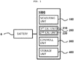
FIG. 1 is a block diagram illustrating an apparatus for a battery management system (BMS) according to the present invention. -
FIGS. 2 and3 illustrate examples of a temperature graph of a battery according to a state of charge (SOC) of the battery of the apparatus for a BMS according to the present invention. -
FIG. 4 illustrates another example of the temperature graph of the battery according to the SOC of the battery of the apparatus for a BMS according to the present invention. -
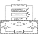
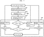
FIGS. 5 to 7 are flowcharts of the control method for an apparatus for a BMS according to the present invention. - Hereinafter, an apparatus and a control method for a battery management system (BMS) according to the present invention will be described in detail with reference to the accompanying drawings.
- As illustrated in
FIG. 1 , anapparatus 1000 for a battery management system (BMS) according to the present invention may include ameasuring unit 100, a calculatingunit 200, and acontrol unit 300. In addition, the calculatingunit 200 may include a first calculatingunit 210 and a second calculatingunit 220. - The respective components will be described in detail. The
measuring unit 100 may measure or estimate a temperature T, a state of charge (SOC) C, a voltage V, and a charging current I of a battery B. - The temperature T, the voltage V, and the charging current I of the battery B may be measured using well-known measuring instruments or methods, and the SOC C of the battery B is generally impossible to directly measure, and may thus be estimated by an indirect method. As an example, in order to estimate the SOC C of the battery B, information on the measured temperature T, voltage V, and/or charging current I of the battery B may be used, but the estimation method of the SOC C of the battery B is not limited thereto, and the SOC C of the battery B may be estimated by various conventionally known methods.
- The first calculating
unit 210 may calculate a temperature change amount ΔT/ΔC for each charge amount of the temperature T of the battery B with respect to the SOC C or the voltage V of the battery, based on information on the temperature T, SOC C and voltage V of a plurality of batteries measured at different time points t in themeasuring unit 100. - The second calculating
unit 220 may calculate an expected temperature T_exp of the battery B expected when the SOC C of the battery is charged with a first reference value C_th1, based on information on the temperature T, SOC C, and temperature change amount ΔT/ΔC for each charge amount of the battery B. - The calculating
unit 200 will be described in more detail. The first calculatingunit 210 may calculate the temperature change amount ΔT/ΔC for each charge amount based on information on a first SOC C1, a second SOC C2, a first temperature T1, and a second temperature T2 as illustrated in Table 1 below. Table 1 below illustrates the SOC C and temperature T of the battery measured at different time points t.[Table 1] Time Point (t) SOC (C) Temperature (T) t1 C1 T1 t2 C2 T2 t3 C3 T3 ... ... ... t(k-2) C(k-2) T(k-2) t(k-1) C(k-1) T(k-1) t(k) C(k) T(k) ... ... ... - Since the temperature T of the battery B changes in relation to the SOC C of the battery, it may be expressed as Equation 1 below.

- In addition, Equation 1 above may be approximated as Equation 2 below.

- Equation 2 above is a function of a trend line L of
FIG. 2 and r1 of Equation 2 is the temperature change amount ΔT/ΔC for each charge amount, and therefore, if the first SOC C1, the second SOC C2, the first temperature T1, and the second temperature T2 are substituted into Equation 2, r1, that is, the temperature change amount ΔT/ΔC for each charge amount, may be calculated as (T2-T1)/(C2-C1). Since r0 is also similarly known, the second calculatingunit 220 may calculate the expected temperature T_exp expected by substituting the first reference value C_th1 into C of Equation 2 in which r0 and r1 are calculated. - In addition, Equation 1 above may be approximated as Equation 3 below.

- As illustrated in Table 1 and
FIG. 3 , when a current time point is t3, the first calculatingunit 210 calculates r0, r1, and r2 of Equation 3 using information on the temperature T and the SOC C of the battery B at previous time points t1 and t2 such that the second calculatingunit 220 may calculate the expected temperature T_exp expected by substituting the first reference value C_th1 into C of Equation 3 in which r0, r1, and r2 are calculated. - Similarly, when a current time point is t(k), the first calculating
unit 210 calculates r0, r1, and r2 of Equation 3 using information on the temperature T and the SOC C of the battery B at previous time points t(k-2) and t(k-1) such that the second calculatingunit 220 may calculate the expected temperature T_exp expected by substituting the first reference value C_th1 into C of Equation 3 in which r0, r1, and r2 are calculated. - At this time, if a trend equation of the temperature T of the battery according to the SOC C of the battery B is approximated as Equation 3, a more accurate expected temperature T_exp than the approximation as Equation 2 may be calculated and the
control unit 300 may also calculate the charging current I more accurately, which has the effect of rapid charging. - The
apparatus 1000 for a BMS according to the present invention may approximate Equation 1 using the temperature T of the battery according to the SOC C of the battery B at the current time point and one or two previous time points as illustrated in Equations 2 and 3 above, and may also approximate Equation 1 using the SOC C and the temperature T of the battery B at two or more previous time points. - On the other hand, the
control unit 300 may control a first charging current I_c1 based on information obtained by comparing the expected temperature T_exp calculated by the second calculatingunit 220 and the first reference temperature T_th1 determined by the user, and charge the battery with the first charging current I_c1. - In detail, the
control unit 300 may control the first charging current I_c1 by increasing the first charging current I_c1 when the expected temperature T_exp of the trend line L is the first reference temperature T_th1 or less as illustrated inFIGS. 2A or3 , and decreasing the first charging current I_c1 when the expected temperature T_exp of the trend line L is the first reference temperature T_th1 or more as illustrated inFIGS. 2B or3 . - On the other hand, as illustrated in
FIG. 1 , theapparatus 1000 for a BMS may further include astorage unit 400. Thestorage unit 400 may learn the stored history of data that has been charged in the past. - The
storage unit 400 will be described in more detail. When the first charging current I_c1 is controlled by comparing the expected temperature T_exp calculated by the second calculatingunit 200 and the first reference temperature T_th1, thestorage unit 400 may store and learn data of an optimal charging current I_opt that the expected temperature T_exp according to the SOC C, the temperature T, and the temperature change amount ΔT/ΔC for each charge amount of the battery B is equal to the first reference temperature T_th1 as illustrated in Table 2 below. Therefore, when the expected temperature T_exp is different from the first reference temperature T_th1, the optimal charging current I_opt that the expected temperature T_exp is equal to the first reference temperature T_th1 may be immediately calculated without gradually increasing or decreasing the first charging current I_c1.[Table 2] SOC (C) Temperatu re (T) ΔT/ΔC Expected Temperature (T_exp) I_opt ... ... ... ... ... C(k) T(k) ΔT/ΔC(k) T_exp(k) I_opt(k) C(k+1) T(k+1) ΔT/ΔC(k+1) T_exp(k+1) I_opt(k+1 ) C(k+2) T(k+2) ΔT/ΔC(k+2) T_exp(k+2) I_opt(k+2 ) ... ... ... ... ... - Further, if the
storage unit 400 stores and learns the data of the optimal charging current I_opt that the expected temperature T_exp according to the SOC C, the temperature T, and the temperature change amount ΔT/ΔC for each charge amount of the battery B is equal to the first reference temperature T_th1 as illustrated in Table 2 above, thestorage unit 400 may calculate the optimal charging current I_opt using the SOC C and the temperature T of the battery B at the current time point, a predetermined first reference temperature T_th1, and a first reference value C_th1. Here, the predetermined first reference temperature T_th1 and the first reference value C_th1 may be determined by the user. - In more detail, the temperature change amount ΔT/ΔC for each charge amount may be calculated as Equation 4 below using the SOC C and the temperature T of the battery B measured at the current time point, the first reference temperature T_th1, and the first reference value C_th1, and

- The optimal charging current I_opt may be calculated as illustrated in Equation 5 below using the optimal charging current I_opt according to the SOC C, the temperature T, and the temperature change amount ΔT/ΔC for each charge amount of the battery B as illustrated in Table 2 above.

- Therefore, even if characteristics of the optimal charging current (I_opt) according to the SOC C, the temperature T, and the temperature change amount ΔT/ΔC for each charge amount are unknown depending on each battery B cell, the
apparatus 1000 for a BMS according to the present invention has an effect of suppressing deterioration of the battery cell while rapidly charging a secondary battery by calculating the optimal charging current I_opt by grasping the characteristics of the battery B cell. - In addition, when the temperature T of the battery B measured by the measuring
unit 100 exceeds the first reference temperature T_th1, thecontrol unit 300 may charge the battery B with a second charging current I_c2 that is the first charging current I_c1 or less, as the charging current I of the battery B. That is, the second charging current I_c2 may be a value that is less than the first charging current I-c1. At this time, the second charging current I_c2 may be 50 to 99% of the first charging current I_c1. - In addition, when the SOC C of the battery B measured by the measuring
unit 100 exceeds the first reference value C_th1, thecontrol unit 300 may charge the battery B with a third charging current I_c3 that is different from the first charging current I_c1, as the charging current I of the battery B. That is, the third charging current I_c3 may be a value that is less than the first charging current I-c1. At this time, the third charging current I_c3 may be 50 to 99% of the first charging current I_c1. - As described above, the first calculating
unit 210 approximates Equation of the temperature T of the battery B according to the SOC C of the battery B by calculating the temperature change amount ΔT/ΔC for each charge amount of the battery B, the second calculatingunit 220 calculates the expected temperature T_exp of the battery B expected when the SOC C of the battery B is charged with the first reference value C_th1 using the approximated Equation, and thecontrol unit 300 calculates the first charging current I_c1 and charges the battery B by decreasing or changing the charging current I of the battery B when the temperature T or the SOC C of the battery B exceeds the first reference temperature T_th1 or the first reference value C_th1. - On the other hand, the
apparatus 1000 for a BMS according to the present invention may charge the battery B by setting a plurality of reference temperatures of the battery B and a plurality of reference values of the SOC C of the battery B to calculate the charging current I of the battery B. - For example, as illustrated in
FIG. 4 , when the temperature T of the battery B exceeds the first reference temperature T_th1 or the SOC C of the battery B exceeds the first reference value C_th1, thecontrol unit 300 does not change the charging current I of the battery B to the second charging current I_c2 or the third charging current I_c3, the first calculatingunit 210 calculates trend equations of trend lines L1', L2', and L3' of the temperature T of the battery B according to the SOC C of the battery B as illustrated in Equation 2 or 3 by calculating the temperature change amount ΔT/ΔC for each charge amount of the battery B again, the second calculatingunit 220 calculates the expected temperature T_exp of the battery B expected when the SOC C of the battery B is charged with the second reference value C_th2 using the calculated trend equations, and thecontrol unit 300 may charge the battery B such as L3' by increasing the charging current I when the expected temperature T_exp is the second reference temperature T_th2 or less such as an extension line of L3, and charge the battery B such as L1' by decreasing the charging current I when the expected temperature T_exp is the second reference temperature T_th2 or more such as an extension line of L1. - As such, by setting the plurality of reference temperatures, it is possible to more reliably prevent the temperature of the battery B cell from reaching the temperature at which the deterioration of the cell occurs, and by setting the plurality of reference values of the SOC C of the battery B, the SOC C of the battery B may reach a specific reference value more quickly, thereby allowing rapid charging.
- Hereinafter, a control method for an
apparatus 1000 for a BMS will be described in detail. - As illustrated in
FIG. 5 , a control method for anapparatus 1000 for a BMS according to the present invention may include a measuring step S100, a calculating step S200, and a controlling step S300. In addition, the calculating step S200 may include a first calculating step S210 and a second calculating step S220. The respective steps will be described in detail. In the measuring step S100, a temperature T, a state of charge (SOC) C, a voltage V, and a charging current I of a battery B may be measured or estimated. In addition, in the first calculating step S210, a temperature change amount ΔT/ΔC for each charge amount of the temperature T of the battery B that rises to increase a unit level ΔC of the SOC may be calculated based on information on the temperature T, SOC C and voltage V of a plurality of batteries measured at different time points t in the measuring step S100, and Equation of the temperature T of the battery B according to the SOC C of the battery B may be approximated. The detailed description has been made in theapparatus 1000 for a BMS, and is thus omitted. - In the second calculating step S220, an expected temperature T_exp of the battery B expected when the SOC C of the battery is charged with a first reference value C_th1 may be calculated based on information on the temperature T, SOC C, and temperature change amount ΔT/ΔC for each charge amount of the battery B, and information on the approximated Equation of the temperature T of the battery B according to the SOC C of the battery B. At this time, in the controlling step S300, a first charging current I_c1 may be calculated by increasing the first charging current I_c1 when the expected temperature T_exp calculated in the second calculating step S220 is a predetermined first reference temperature T_th1 or less, and decreasing the first charging current I_c1 when the expected temperature T_exp is the first reference temperature T_th1 or more.
- On the other hand, as illustrated in
FIG. 5 , the control method for anapparatus 1000 for a BMS for a BMS may further include a storing step S400. In the storing step S400, a stored history of data that has been charged in the past may be learned. - The storing step S400 will be described in more detail. When the first charging current I_c1 is controlled by comparing the expected temperature T_exp calculated in the second calculating step S200 and the first reference temperature T_th1, in the storing step S400, data of an optimal charging current I_opt that the SOC C, the temperature T, and the expected temperature T_exp of the battery B are equal to the first reference temperature T_th1 may be stored and learned by learning an increase or decrease in the first charging current I_c1 as illustrated in
FIG. 5 . Therefore, when the expected temperature T_exp is different from the first reference temperature T_th1, the optimal charging current I_opt that the expected temperature T_exp is equal to the first reference temperature T_th1 may be immediately calculated without gradually increasing or decreasing the first charging current I_c1. - As illustrated in
FIG. 6 , in the controlling step S300, when the temperature T of the battery B measured in the measuring step S100 exceeds the first reference temperature T_th1 or the SOC C of the battery B exceeds the first reference value C_th1, the battery B may be charged with a second charging current I_c2 that is the first charging current I_c1 or less or a third charging current I_c3 that is different from the first charging current I_c1, as the charging current I of the battery B. - According to the apparatus and the control method for a BMS according to various embodiments of the present invention as described above, a relational expression of the battery temperature according to the SOC of the battery is approximated, a charging current of the battery reaching the SOC of the battery and the temperature of the battery that are desired by the user is calculated based on the relational expression, and the battery is charged with the charging current, thereby making it possible to suppress the deterioration of the battery cells while rapidly charging the secondary battery.
- The present invention is not limited to the above-mentioned embodiments, and may be variously applied, and may be variously modified without departing from the gist of the present invention claimed in the claims.
-
- 100
- : measuring unit
- 200
- : calculating unit
- 210
- : first calculating unit
- 220
- : second calculating unit
- 300
- : control unit
- C_th
- : reference value
- T_exp
- : expected temperature
- T_th
- : reference temperature
- S100
- : measuring step
- S200
- : calculating step
- S210
- : first calculating step
- S220
- : second calculating step
- S300
- : controlling step
- S400
- : storing step
Claims (10)
- An apparatus for a battery management system (BMS) comprising:a measuring unit measuring or estimating a temperature, a state of charge (SOC), a voltage, and a charging current of a battery;a first calculating unit calculating a temperature change amount for each charge amount of the temperature of the battery with respect to the SOC or the voltage of the battery, based on the temperature, the SOC, and the voltage of the battery measured at different time points by the measuring unit;a second calculating unit calculating an expected temperature of the battery when the SOC of the battery is charged with a first reference value, based on the temperature, the SOC, and the temperature change amount for each charge amount of the battery; anda control unit controlling a first charging current based on information obtained by comparing the expected temperature calculated by the second calculating unit and a predetermined first reference temperature, and charging the battery with the first charging current.
- The apparatus for a BMS of claim 1, wherein the control unit increases the first charging current when the expected temperature is the first reference temperature or less, and decreases the first charging current when the expected temperature is the first reference temperature or more.
- The apparatus for a BMS of claim 2, wherein the first calculating unit calculates the temperature change amount for each charge amount based on a first SOC, a second SOC, a first temperature, and a second temperature,
the first SOC is the SOC of the battery measured at a first time point, and the second SOC is the SOC of the battery measured at a second time point different from the first time point, and
the first temperature is the temperature of the battery measured at the first time point, and the second temperature is the temperature of the battery measured at the second time point. - The apparatus for a BMS of claim 2, wherein the control unit charges the battery with a second charging current that is the first charging current or less as the charging current of the battery, when the temperature of the battery measured by the measuring unit exceeds the first reference temperature.
- The apparatus for a BMS of claim 2, wherein the control unit charges the battery with a third charging current different from the first charging current as the charging current of the battery, when the SOC of the battery measured by the measuring unit exceeds the first reference value.
- A control method for an apparatus for a battery management system (BMS) comprising:a measuring step of measuring or estimating a temperature, a state of charge (SOC), a voltage, and a charging current of a battery;a first calculating step of calculating a temperature change amount for each charge amount of the temperature of the battery with respect to the SOC or the voltage of the battery, based on the temperature, the SOC, and the voltage of the battery measured at different time points in the measuring step;a second calculating step of calculating an expected temperature of the battery when the SOC of the battery is charged with a first reference value, based on the temperature, the SOC, and the temperature change amount for each charge amount of the battery; anda controlling step of controlling a first charging current based on information obtained by comparing the expected temperature calculated in the second calculating step and a predetermined first reference temperature, and charging the battery with the first charging current.
- The control method for an apparatus for a BMS of claim 6, wherein in the controlling step, the first charging current is increased when the expected temperature is the first reference temperature or less, and the first charging current is decreased when the expected temperature is the first reference temperature or more.
- The control method for an apparatus for a BMS of claim 7, wherein in the first calculating step, the temperature change amount for each charge amount is calculated based on a first SOC, a second SOC, a first temperature, and a second temperature,
the first SOC is the SOC of the battery measured at a first time point, and the second SOC is the SOC of the battery measured at a second time point different from the first time point, and
the first temperature is the temperature of the battery measured at the first time point, and the second temperature is the temperature of the battery measured at the second time point. - The control method for an apparatus for a BMS of claim 7, wherein in the controlling step, the battery is charged with a second charging current that is the first charging current or less as the charging current of the battery, when the temperature of the battery measured in the measuring step exceeds the first reference temperature.
- The control method for an apparatus for a BMS of claim 7, wherein in the controlling step, the battery is charged with a third charging current different from the first charging current as the charging current of the battery, when the SOC of the battery measured in the measuring step exceeds the first reference value.
Applications Claiming Priority (1)
| Application Number | Priority Date | Filing Date | Title |
|---|---|---|---|
| KR1020190056742A KR102687127B1 (en) | 2019-05-15 | 2019-05-15 | An apparatus and a control method for battery management system |
Publications (2)
| Publication Number | Publication Date |
|---|---|
| EP3739719A1 true EP3739719A1 (en) | 2020-11-18 |
| EP3739719B1 EP3739719B1 (en) | 2022-08-17 |
Family
ID=70736688
Family Applications (1)
| Application Number | Title | Priority Date | Filing Date |
|---|---|---|---|
| EP20174632.8A Active EP3739719B1 (en) | 2019-05-15 | 2020-05-14 | Apparatus and control method for battery management system |
Country Status (4)
| Country | Link |
|---|---|
| US (1) | US11349327B2 (en) |
| EP (1) | EP3739719B1 (en) |
| KR (1) | KR102687127B1 (en) |
| CN (1) | CN111953032B (en) |
Cited By (2)
| Publication number | Priority date | Publication date | Assignee | Title |
|---|---|---|---|---|
| US11349327B2 (en) * | 2019-05-15 | 2022-05-31 | Sk Innovation Co., Ltd. | Apparatus and control method for battery management system |
| EP4393767A4 (en) * | 2021-12-30 | 2025-02-19 | BYD Company Limited | OVERHEATING PROTECTION METHOD AND APPARATUS FOR CHARGING APPARATUS, AND ELECTRIC VEHICLE |
Families Citing this family (9)
| Publication number | Priority date | Publication date | Assignee | Title |
|---|---|---|---|---|
| CN109270465A (en) * | 2018-11-01 | 2019-01-25 | 桑顿新能源科技有限公司 | A kind of charging time evaluation method considering temperature rise |
| KR102928975B1 (en) * | 2021-01-25 | 2026-02-19 | 주식회사 엘지에너지솔루션 | Apparatus and method for managing battery |
| US12081061B2 (en) * | 2021-02-23 | 2024-09-03 | Envoy Medical Corporation | Predicting a cumulative thermal dose in implantable battery recharge systems and methods |
| CN115117949A (en) * | 2021-03-23 | 2022-09-27 | 比亚迪股份有限公司 | Battery current limiting method, equipment and storage medium |
| CN113125967B (en) * | 2021-04-07 | 2023-04-28 | 力高(山东)新能源技术股份有限公司 | Lithium battery SOE calculation method based on temperature rise prediction |
| CN112977166B (en) * | 2021-04-19 | 2022-07-29 | 厦门金龙联合汽车工业有限公司 | Self-adaptive energy-saving time-saving control method for charging of electric automobile |
| KR102348505B1 (en) * | 2021-09-24 | 2022-01-07 | 주식회사 지이솔루션 | A rechargeable battery pack with a set amount of charge |
| CN116424149A (en) * | 2023-02-17 | 2023-07-14 | 宇通客车股份有限公司 | A charging and swapping system over-temperature protection method and device |
| CN117485204A (en) * | 2023-11-02 | 2024-02-02 | 长城汽车股份有限公司 | Vehicle battery management method, device, medium and vehicle |
Citations (3)
| Publication number | Priority date | Publication date | Assignee | Title |
|---|---|---|---|---|
| KR101249347B1 (en) | 2010-11-04 | 2013-04-01 | 주식회사 엘지화학 | Secondary battery having temperature measuring pad and Protection apparatus for the same |
| EP3252918A1 (en) * | 2015-08-21 | 2017-12-06 | LG Chem, Ltd. | Apparatus and method for adjusting charging condition of secondary battery |
| US20190064282A1 (en) * | 2017-08-23 | 2019-02-28 | Toyota Jidosha Kabushiki Kaisha | Method of estimating deteriorated state of secondary battery and secondary battery system |
Family Cites Families (46)
| Publication number | Priority date | Publication date | Assignee | Title |
|---|---|---|---|---|
| JP4379925B2 (en) * | 1998-04-21 | 2009-12-09 | 住友金属工業株式会社 | Graphite powder suitable for anode material of lithium ion secondary battery |
| KR100414979B1 (en) * | 2000-03-13 | 2004-01-14 | 니폰 덴신 덴와 가부시끼가이샤 | Capacity estimation method, degradation estimation method and degradation estimation apparatus for lithium-ion cells, and lithium-ion batteries |
| GB2413225B (en) * | 2001-05-14 | 2005-12-28 | Eaton Power Quality Ltd | Battery charge management |
| JP3672248B2 (en) * | 2001-09-19 | 2005-07-20 | インターナショナル・ビジネス・マシーンズ・コーポレーション | Electrical apparatus, computer apparatus, intelligent battery, battery diagnosis method, battery state display method, and program |
| TW530429B (en) * | 2001-12-24 | 2003-05-01 | Avid Electronics Corp | Intelligent secondary battery management method and device |
| JP2004003460A (en) * | 2002-04-09 | 2004-01-08 | Toyota Motor Corp | Vehicle control device and control method |
| JP2004301782A (en) * | 2003-03-31 | 2004-10-28 | Yazaki Corp | Fully charged state detecting device and method, charged state detecting device and method, deterioration degree detecting device and method |
| JP2005019019A (en) * | 2003-06-23 | 2005-01-20 | Yazaki Corp | Battery degradation determination method and apparatus |
| DE10341188A1 (en) * | 2003-09-06 | 2005-04-14 | Dräger Safety AG & Co. KGaA | Battery assembly and method for controlling the state of charge of a battery assembly |
| JP4438088B2 (en) * | 2004-03-31 | 2010-03-24 | スズキ株式会社 | Charge state detection device for secondary battery for vehicle |
| JP2005333738A (en) * | 2004-05-20 | 2005-12-02 | Toyota Motor Corp | COOLING DEVICE CONTROL DEVICE, COOLING DEVICE ABNORMALITY DETECTING METHOD, COOLING DEVICE ABNORMALITY DETECTING METHOD, AND COMPUTER-READABLE RECORDING MEDIUM CONTAINING PROGRAM FOR CAUSING COMPUTER TO EXECUTE COOLING DEVICE ABNORMALITY |
| KR20070051916A (en) * | 2004-08-25 | 2007-05-18 | 닛본 덴끼 가부시끼가이샤 | Internal impedance detection device, internal impedance detection method, deterioration detection device and deterioration detection method |
| JP4495116B2 (en) * | 2005-06-30 | 2010-06-30 | エルジー・ケム・リミテッド | Battery remaining capacity estimation method and battery management system using the same |
| KR100804697B1 (en) * | 2006-08-11 | 2008-02-18 | 삼성에스디아이 주식회사 | Battery Management System and Its Driving Method |
| KR100851444B1 (en) * | 2006-11-03 | 2008-08-08 | 세방전지주식회사 | Charge control device and method |
| JP2008136278A (en) * | 2006-11-27 | 2008-06-12 | Matsushita Electric Works Ltd | Charger |
| JP5279199B2 (en) * | 2007-05-23 | 2013-09-04 | キヤノン株式会社 | Charging apparatus and charging control method |
| JP5219485B2 (en) * | 2007-12-12 | 2013-06-26 | 三洋電機株式会社 | Charging method |
| KR101042768B1 (en) * | 2008-06-03 | 2011-06-20 | 삼성에스디아이 주식회사 | Battery pack and its charging method |
| US9634516B2 (en) * | 2009-04-14 | 2017-04-25 | Ford Global Technologies, Llc | Method and system for monitoring temperature of a power distribution circuit |
| US11376973B2 (en) * | 2009-04-14 | 2022-07-05 | Ford Global Technologies, Llc | Method and system for monitoring temperature of a power distribution circuit |
| US9397519B2 (en) * | 2009-04-14 | 2016-07-19 | Ford Global Technologies, Llc | Method and system for controlling current of a power distribution circuit |
| DE102009002468A1 (en) * | 2009-04-17 | 2010-10-21 | Robert Bosch Gmbh | Determining the internal resistance of a battery cell of a traction battery when using inductive cell balancing |
| JP4807443B2 (en) * | 2009-07-08 | 2011-11-02 | トヨタ自動車株式会社 | Secondary battery temperature estimation device |
| US20140132214A1 (en) * | 2011-06-17 | 2014-05-15 | Toyota Jidosha Kabushiki Kaisha | Electrically powered vehicle and method for controlling electrically powered vehicle |
| KR101609076B1 (en) | 2011-08-01 | 2016-04-04 | 알프스 그린 디바이스 가부시키가이샤 | Battery device temperature measurement method |
| US9142977B1 (en) * | 2012-12-13 | 2015-09-22 | Atieva, Inc. | Method of controlling battery state using constant-voltage discharge |
| KR20140139322A (en) * | 2013-05-27 | 2014-12-05 | 삼성에스디아이 주식회사 | Battery management system and driving method thereof |
| JP2015155859A (en) * | 2014-02-21 | 2015-08-27 | ソニー株式会社 | Battery remaining amount estimating device, battery pack, power storage device, electric vehicle, and battery remaining amount estimating method |
| US9906069B2 (en) * | 2014-07-28 | 2018-02-27 | Ford Global Technologies, Llc | Vehicle battery status detection by tracking a temperature gradient |
| JP6162884B2 (en) * | 2014-09-08 | 2017-07-12 | 株式会社東芝 | Battery pack, control circuit, and control method |
| KR102267626B1 (en) * | 2014-11-20 | 2021-06-22 | 삼성전자주식회사 | Electronic device and method for managementting bettertyby the electronic device |
| KR101685130B1 (en) * | 2014-12-19 | 2016-12-09 | 주식회사 엘지화학 | Apparatus and Method for controlling power for secondary battery |
| KR102527327B1 (en) * | 2015-10-12 | 2023-04-27 | 삼성전자주식회사 | Apparatus and method for temperature estimating of battery, apparatus and method for managing battery |
| KR102559199B1 (en) * | 2015-11-02 | 2023-07-25 | 삼성전자주식회사 | Method of managing battery and batter management appratus |
| US10224579B2 (en) * | 2015-12-31 | 2019-03-05 | Robert Bosch Gmbh | Evaluating capacity fade in dual insertion batteries using potential and temperature measurements |
| CN106208241A (en) * | 2016-08-24 | 2016-12-07 | 东莞新能德科技有限公司 | Battery charge management method and system |
| WO2018058402A1 (en) | 2016-09-29 | 2018-04-05 | 深圳市柔宇科技有限公司 | Fast charging control method, fast charging control system, and terminal device |
| CN108666600B (en) * | 2017-03-30 | 2021-01-08 | 中国科学院金属研究所 | A SOC detection method for all-vanadium redox flow battery based on thermochemical measurement |
| KR101998069B1 (en) | 2017-06-23 | 2019-07-09 | 이정환 | Method and apparatus for fast charging and maximum discharging with less-degradation of battery for an electric car |
| JP6933109B2 (en) * | 2017-11-29 | 2021-09-08 | トヨタ自動車株式会社 | Deterioration state estimation method for secondary batteries and secondary battery system |
| KR102255485B1 (en) * | 2018-01-26 | 2021-05-24 | 주식회사 엘지에너지솔루션 | Apparatus and Method for Estimating SOH of Secondary Battery |
| CN111257752B (en) * | 2018-11-30 | 2021-02-26 | 宁德时代新能源科技股份有限公司 | Remaining charging time estimation method, device, system and storage medium |
| US11585859B2 (en) * | 2019-03-01 | 2023-02-21 | Chongqing Jinkang Powertrain New Energy Co., Ltd. | State of charge error estimation of battery cells background |
| KR102687127B1 (en) * | 2019-05-15 | 2024-07-23 | 에스케이온 주식회사 | An apparatus and a control method for battery management system |
| CN113311347B (en) * | 2020-02-27 | 2023-02-21 | 凹凸电子(武汉)有限公司 | Apparatus, method and system for estimating available state of charge of battery |
-
2019
- 2019-05-15 KR KR1020190056742A patent/KR102687127B1/en active Active
-
2020
- 2020-05-14 US US15/931,822 patent/US11349327B2/en active Active
- 2020-05-14 EP EP20174632.8A patent/EP3739719B1/en active Active
- 2020-05-14 CN CN202010408889.2A patent/CN111953032B/en active Active
Patent Citations (3)
| Publication number | Priority date | Publication date | Assignee | Title |
|---|---|---|---|---|
| KR101249347B1 (en) | 2010-11-04 | 2013-04-01 | 주식회사 엘지화학 | Secondary battery having temperature measuring pad and Protection apparatus for the same |
| EP3252918A1 (en) * | 2015-08-21 | 2017-12-06 | LG Chem, Ltd. | Apparatus and method for adjusting charging condition of secondary battery |
| US20190064282A1 (en) * | 2017-08-23 | 2019-02-28 | Toyota Jidosha Kabushiki Kaisha | Method of estimating deteriorated state of secondary battery and secondary battery system |
Cited By (2)
| Publication number | Priority date | Publication date | Assignee | Title |
|---|---|---|---|---|
| US11349327B2 (en) * | 2019-05-15 | 2022-05-31 | Sk Innovation Co., Ltd. | Apparatus and control method for battery management system |
| EP4393767A4 (en) * | 2021-12-30 | 2025-02-19 | BYD Company Limited | OVERHEATING PROTECTION METHOD AND APPARATUS FOR CHARGING APPARATUS, AND ELECTRIC VEHICLE |
Also Published As
| Publication number | Publication date |
|---|---|
| KR20200132002A (en) | 2020-11-25 |
| KR102687127B1 (en) | 2024-07-23 |
| US20200366118A1 (en) | 2020-11-19 |
| US11349327B2 (en) | 2022-05-31 |
| CN111953032A (en) | 2020-11-17 |
| EP3739719B1 (en) | 2022-08-17 |
| CN111953032B (en) | 2025-09-09 |
Similar Documents
| Publication | Publication Date | Title |
|---|---|---|
| EP3739719B1 (en) | Apparatus and control method for battery management system | |
| US10340714B2 (en) | System for controlling output parameter of secondary battery, and method therefor | |
| EP3786654B1 (en) | Battery pack soc correction method, battery management system, and vehicle | |
| EP2320242B1 (en) | Apparatus and method for cell balancing using the voltage variation behavior of battery cell | |
| JP7054868B2 (en) | Battery management system, battery system, and vehicle power supply system | |
| US11125825B2 (en) | Apparatus and method for managing battery | |
| US7982433B2 (en) | Method of adjusting SOC for battery and battery management system using the same | |
| JP2008547365A (en) | Method and apparatus for adjusting charge or discharge output of battery | |
| KR102160272B1 (en) | Battery management apparatus and method for protecting a lithium iron phosphate cell from over-voltage using the same | |
| EP3828568B1 (en) | Battery management apparatus, battery management method and battery pack | |
| US11095130B2 (en) | Power storage apparatus for estimating an open-circuit voltage | |
| KR101912615B1 (en) | System for monitoring and protecting batteries | |
| EP3379277B1 (en) | Capacity maintenance rate estimation apparatus or capacity maintenance rate estimation method | |
| EP3730957A1 (en) | Charge capacity calculation device and method for energy storage system | |
| US20180067167A1 (en) | Storage system, storage control method, and storage control program | |
| WO2018061449A1 (en) | Battery control device, battery system, and vehicle | |
| US12276704B2 (en) | Maximum discharge current prediction method and battery system using the same | |
| US10948543B2 (en) | System for determining a discharge power limit value and a charge power limit value of a battery cell | |
| EP3323665B1 (en) | A battery pack balancing system and method | |
| JP7810362B2 (en) | Electronic equipment and measurement method | |
| KR102375843B1 (en) | Apparatus and method for managing battery | |
| KR20250042248A (en) | Method and apparatus for determining abnormal deterioration state of battery cell | |
| US11500029B2 (en) | Battery estimation method and device, and method of generating battery potential difference parameter term | |
| KR20220124398A (en) | Vehicle and its control method | |
| Alsharif et al. | The Development of a Risk Oriented State-of-Charge Estimation Algorithm for a Heavy-Duty FCEV Truck |
Legal Events
| Date | Code | Title | Description |
|---|---|---|---|
| PUAI | Public reference made under article 153(3) epc to a published international application that has entered the european phase |
Free format text: ORIGINAL CODE: 0009012 |
|
| STAA | Information on the status of an ep patent application or granted ep patent |
Free format text: STATUS: REQUEST FOR EXAMINATION WAS MADE |
|
| 17P | Request for examination filed |
Effective date: 20200514 |
|
| AK | Designated contracting states |
Kind code of ref document: A1 Designated state(s): AL AT BE BG CH CY CZ DE DK EE ES FI FR GB GR HR HU IE IS IT LI LT LU LV MC MK MT NL NO PL PT RO RS SE SI SK SM TR |
|
| AX | Request for extension of the european patent |
Extension state: BA ME |
|
| GRAP | Despatch of communication of intention to grant a patent |
Free format text: ORIGINAL CODE: EPIDOSNIGR1 |
|
| STAA | Information on the status of an ep patent application or granted ep patent |
Free format text: STATUS: GRANT OF PATENT IS INTENDED |
|
| INTG | Intention to grant announced |
Effective date: 20220310 |
|
| GRAS | Grant fee paid |
Free format text: ORIGINAL CODE: EPIDOSNIGR3 |
|
| GRAA | (expected) grant |
Free format text: ORIGINAL CODE: 0009210 |
|
| STAA | Information on the status of an ep patent application or granted ep patent |
Free format text: STATUS: THE PATENT HAS BEEN GRANTED |
|
| AK | Designated contracting states |
Kind code of ref document: B1 Designated state(s): AL AT BE BG CH CY CZ DE DK EE ES FI FR GB GR HR HU IE IS IT LI LT LU LV MC MK MT NL NO PL PT RO RS SE SI SK SM TR |
|
| REG | Reference to a national code |
Ref country code: CH Ref legal event code: EP |
|
| REG | Reference to a national code |
Ref country code: DE Ref legal event code: R096 Ref document number: 602020004531 Country of ref document: DE |
|
| REG | Reference to a national code |
Ref country code: IE Ref legal event code: FG4D |
|
| REG | Reference to a national code |
Ref country code: AT Ref legal event code: REF Ref document number: 1512802 Country of ref document: AT Kind code of ref document: T Effective date: 20220915 |
|
| REG | Reference to a national code |
Ref country code: NL Ref legal event code: MP Effective date: 20220817 |
|
| REG | Reference to a national code |
Ref country code: LT Ref legal event code: MG9D |
|
| PG25 | Lapsed in a contracting state [announced via postgrant information from national office to epo] |
Ref country code: SE Free format text: LAPSE BECAUSE OF FAILURE TO SUBMIT A TRANSLATION OF THE DESCRIPTION OR TO PAY THE FEE WITHIN THE PRESCRIBED TIME-LIMIT Effective date: 20220817 Ref country code: RS Free format text: LAPSE BECAUSE OF FAILURE TO SUBMIT A TRANSLATION OF THE DESCRIPTION OR TO PAY THE FEE WITHIN THE PRESCRIBED TIME-LIMIT Effective date: 20220817 Ref country code: PT Free format text: LAPSE BECAUSE OF FAILURE TO SUBMIT A TRANSLATION OF THE DESCRIPTION OR TO PAY THE FEE WITHIN THE PRESCRIBED TIME-LIMIT Effective date: 20221219 Ref country code: NO Free format text: LAPSE BECAUSE OF FAILURE TO SUBMIT A TRANSLATION OF THE DESCRIPTION OR TO PAY THE FEE WITHIN THE PRESCRIBED TIME-LIMIT Effective date: 20221117 Ref country code: NL Free format text: LAPSE BECAUSE OF FAILURE TO SUBMIT A TRANSLATION OF THE DESCRIPTION OR TO PAY THE FEE WITHIN THE PRESCRIBED TIME-LIMIT Effective date: 20220817 Ref country code: LV Free format text: LAPSE BECAUSE OF FAILURE TO SUBMIT A TRANSLATION OF THE DESCRIPTION OR TO PAY THE FEE WITHIN THE PRESCRIBED TIME-LIMIT Effective date: 20220817 Ref country code: LT Free format text: LAPSE BECAUSE OF FAILURE TO SUBMIT A TRANSLATION OF THE DESCRIPTION OR TO PAY THE FEE WITHIN THE PRESCRIBED TIME-LIMIT Effective date: 20220817 Ref country code: FI Free format text: LAPSE BECAUSE OF FAILURE TO SUBMIT A TRANSLATION OF THE DESCRIPTION OR TO PAY THE FEE WITHIN THE PRESCRIBED TIME-LIMIT Effective date: 20220817 |
|
| RAP2 | Party data changed (patent owner data changed or rights of a patent transferred) |
Owner name: SK ON CO., LTD. |
|
| REG | Reference to a national code |
Ref country code: AT Ref legal event code: MK05 Ref document number: 1512802 Country of ref document: AT Kind code of ref document: T Effective date: 20220817 |
|
| REG | Reference to a national code |
Ref country code: DE Ref legal event code: R081 Ref document number: 602020004531 Country of ref document: DE Owner name: SK ON CO., LTD., KR Free format text: FORMER OWNER: SK INNOVATION CO., LTD., SEOUL, KR |
|
| PG25 | Lapsed in a contracting state [announced via postgrant information from national office to epo] |
Ref country code: PL Free format text: LAPSE BECAUSE OF FAILURE TO SUBMIT A TRANSLATION OF THE DESCRIPTION OR TO PAY THE FEE WITHIN THE PRESCRIBED TIME-LIMIT Effective date: 20220817 Ref country code: IS Free format text: LAPSE BECAUSE OF FAILURE TO SUBMIT A TRANSLATION OF THE DESCRIPTION OR TO PAY THE FEE WITHIN THE PRESCRIBED TIME-LIMIT Effective date: 20221217 Ref country code: HR Free format text: LAPSE BECAUSE OF FAILURE TO SUBMIT A TRANSLATION OF THE DESCRIPTION OR TO PAY THE FEE WITHIN THE PRESCRIBED TIME-LIMIT Effective date: 20220817 Ref country code: GR Free format text: LAPSE BECAUSE OF FAILURE TO SUBMIT A TRANSLATION OF THE DESCRIPTION OR TO PAY THE FEE WITHIN THE PRESCRIBED TIME-LIMIT Effective date: 20221118 |
|
| PG25 | Lapsed in a contracting state [announced via postgrant information from national office to epo] |
Ref country code: SM Free format text: LAPSE BECAUSE OF FAILURE TO SUBMIT A TRANSLATION OF THE DESCRIPTION OR TO PAY THE FEE WITHIN THE PRESCRIBED TIME-LIMIT Effective date: 20220817 Ref country code: RO Free format text: LAPSE BECAUSE OF FAILURE TO SUBMIT A TRANSLATION OF THE DESCRIPTION OR TO PAY THE FEE WITHIN THE PRESCRIBED TIME-LIMIT Effective date: 20220817 Ref country code: ES Free format text: LAPSE BECAUSE OF FAILURE TO SUBMIT A TRANSLATION OF THE DESCRIPTION OR TO PAY THE FEE WITHIN THE PRESCRIBED TIME-LIMIT Effective date: 20220817 Ref country code: DK Free format text: LAPSE BECAUSE OF FAILURE TO SUBMIT A TRANSLATION OF THE DESCRIPTION OR TO PAY THE FEE WITHIN THE PRESCRIBED TIME-LIMIT Effective date: 20220817 Ref country code: CZ Free format text: LAPSE BECAUSE OF FAILURE TO SUBMIT A TRANSLATION OF THE DESCRIPTION OR TO PAY THE FEE WITHIN THE PRESCRIBED TIME-LIMIT Effective date: 20220817 Ref country code: AT Free format text: LAPSE BECAUSE OF FAILURE TO SUBMIT A TRANSLATION OF THE DESCRIPTION OR TO PAY THE FEE WITHIN THE PRESCRIBED TIME-LIMIT Effective date: 20220817 |
|
| REG | Reference to a national code |
Ref country code: DE Ref legal event code: R097 Ref document number: 602020004531 Country of ref document: DE |
|
| PG25 | Lapsed in a contracting state [announced via postgrant information from national office to epo] |
Ref country code: SK Free format text: LAPSE BECAUSE OF FAILURE TO SUBMIT A TRANSLATION OF THE DESCRIPTION OR TO PAY THE FEE WITHIN THE PRESCRIBED TIME-LIMIT Effective date: 20220817 Ref country code: EE Free format text: LAPSE BECAUSE OF FAILURE TO SUBMIT A TRANSLATION OF THE DESCRIPTION OR TO PAY THE FEE WITHIN THE PRESCRIBED TIME-LIMIT Effective date: 20220817 |
|
| REG | Reference to a national code |
Ref country code: GB Ref legal event code: 732E Free format text: REGISTERED BETWEEN 20230511 AND 20230517 |
|
| PLBE | No opposition filed within time limit |
Free format text: ORIGINAL CODE: 0009261 |
|
| STAA | Information on the status of an ep patent application or granted ep patent |
Free format text: STATUS: NO OPPOSITION FILED WITHIN TIME LIMIT |
|
| PG25 | Lapsed in a contracting state [announced via postgrant information from national office to epo] |
Ref country code: AL Free format text: LAPSE BECAUSE OF FAILURE TO SUBMIT A TRANSLATION OF THE DESCRIPTION OR TO PAY THE FEE WITHIN THE PRESCRIBED TIME-LIMIT Effective date: 20220817 |
|
| P01 | Opt-out of the competence of the unified patent court (upc) registered |
Effective date: 20230602 |
|
| 26N | No opposition filed |
Effective date: 20230519 |
|
| PG25 | Lapsed in a contracting state [announced via postgrant information from national office to epo] |
Ref country code: SI Free format text: LAPSE BECAUSE OF FAILURE TO SUBMIT A TRANSLATION OF THE DESCRIPTION OR TO PAY THE FEE WITHIN THE PRESCRIBED TIME-LIMIT Effective date: 20220817 |
|
| REG | Reference to a national code |
Ref country code: CH Ref legal event code: PL |
|
| PG25 | Lapsed in a contracting state [announced via postgrant information from national office to epo] |
Ref country code: MC Free format text: LAPSE BECAUSE OF FAILURE TO SUBMIT A TRANSLATION OF THE DESCRIPTION OR TO PAY THE FEE WITHIN THE PRESCRIBED TIME-LIMIT Effective date: 20220817 |
|
| REG | Reference to a national code |
Ref country code: BE Ref legal event code: MM Effective date: 20230531 |
|
| PG25 | Lapsed in a contracting state [announced via postgrant information from national office to epo] |
Ref country code: MC Free format text: LAPSE BECAUSE OF FAILURE TO SUBMIT A TRANSLATION OF THE DESCRIPTION OR TO PAY THE FEE WITHIN THE PRESCRIBED TIME-LIMIT Effective date: 20220817 Ref country code: LU Free format text: LAPSE BECAUSE OF NON-PAYMENT OF DUE FEES Effective date: 20230514 Ref country code: LI Free format text: LAPSE BECAUSE OF NON-PAYMENT OF DUE FEES Effective date: 20230531 Ref country code: CH Free format text: LAPSE BECAUSE OF NON-PAYMENT OF DUE FEES Effective date: 20230531 |
|
| REG | Reference to a national code |
Ref country code: IE Ref legal event code: MM4A |
|
| PG25 | Lapsed in a contracting state [announced via postgrant information from national office to epo] |
Ref country code: IE Free format text: LAPSE BECAUSE OF NON-PAYMENT OF DUE FEES Effective date: 20230514 |
|
| PG25 | Lapsed in a contracting state [announced via postgrant information from national office to epo] |
Ref country code: IE Free format text: LAPSE BECAUSE OF NON-PAYMENT OF DUE FEES Effective date: 20230514 |
|
| PG25 | Lapsed in a contracting state [announced via postgrant information from national office to epo] |
Ref country code: IT Free format text: LAPSE BECAUSE OF FAILURE TO SUBMIT A TRANSLATION OF THE DESCRIPTION OR TO PAY THE FEE WITHIN THE PRESCRIBED TIME-LIMIT Effective date: 20220817 Ref country code: BE Free format text: LAPSE BECAUSE OF NON-PAYMENT OF DUE FEES Effective date: 20230531 |
|
| PG25 | Lapsed in a contracting state [announced via postgrant information from national office to epo] |
Ref country code: BG Free format text: LAPSE BECAUSE OF FAILURE TO SUBMIT A TRANSLATION OF THE DESCRIPTION OR TO PAY THE FEE WITHIN THE PRESCRIBED TIME-LIMIT Effective date: 20220817 |
|
| PG25 | Lapsed in a contracting state [announced via postgrant information from national office to epo] |
Ref country code: BG Free format text: LAPSE BECAUSE OF FAILURE TO SUBMIT A TRANSLATION OF THE DESCRIPTION OR TO PAY THE FEE WITHIN THE PRESCRIBED TIME-LIMIT Effective date: 20220817 |
|
| PGFP | Annual fee paid to national office [announced via postgrant information from national office to epo] |
Ref country code: DE Payment date: 20250320 Year of fee payment: 6 |
|
| PG25 | Lapsed in a contracting state [announced via postgrant information from national office to epo] |
Ref country code: CY Free format text: LAPSE BECAUSE OF FAILURE TO SUBMIT A TRANSLATION OF THE DESCRIPTION OR TO PAY THE FEE WITHIN THE PRESCRIBED TIME-LIMIT; INVALID AB INITIO Effective date: 20200514 |
|
| PG25 | Lapsed in a contracting state [announced via postgrant information from national office to epo] |
Ref country code: HU Free format text: LAPSE BECAUSE OF FAILURE TO SUBMIT A TRANSLATION OF THE DESCRIPTION OR TO PAY THE FEE WITHIN THE PRESCRIBED TIME-LIMIT; INVALID AB INITIO Effective date: 20200514 |
|
| PG25 | Lapsed in a contracting state [announced via postgrant information from national office to epo] |
Ref country code: TR Free format text: LAPSE BECAUSE OF FAILURE TO SUBMIT A TRANSLATION OF THE DESCRIPTION OR TO PAY THE FEE WITHIN THE PRESCRIBED TIME-LIMIT Effective date: 20220817 |
|
| PGFP | Annual fee paid to national office [announced via postgrant information from national office to epo] |
Ref country code: GB Payment date: 20260324 Year of fee payment: 7 |
|
| PGFP | Annual fee paid to national office [announced via postgrant information from national office to epo] |
Ref country code: FR Payment date: 20260323 Year of fee payment: 7 |