EP3739692A1 - Connector cavity assembly for a medical device and manufacturing method - Google Patents
Connector cavity assembly for a medical device and manufacturing method Download PDFInfo
- Publication number
- EP3739692A1 EP3739692A1 EP19174589.2A EP19174589A EP3739692A1 EP 3739692 A1 EP3739692 A1 EP 3739692A1 EP 19174589 A EP19174589 A EP 19174589A EP 3739692 A1 EP3739692 A1 EP 3739692A1
- Authority
- EP
- European Patent Office
- Prior art keywords
- connector cavity
- connector
- medical device
- housing
- assembly
- Prior art date
- Legal status (The legal status is an assumption and is not a legal conclusion. Google has not performed a legal analysis and makes no representation as to the accuracy of the status listed.)
- Granted
Links
Images



Classifications
-
- A—HUMAN NECESSITIES
- A61—MEDICAL OR VETERINARY SCIENCE; HYGIENE
- A61N—ELECTROTHERAPY; MAGNETOTHERAPY; RADIATION THERAPY; ULTRASOUND THERAPY
- A61N1/00—Electrotherapy; Circuits therefor
- A61N1/18—Applying electric currents by contact electrodes
- A61N1/32—Applying electric currents by contact electrodes alternating or intermittent currents
- A61N1/36—Applying electric currents by contact electrodes alternating or intermittent currents for stimulation
- A61N1/372—Arrangements in connection with the implantation of stimulators
- A61N1/375—Constructional arrangements, e.g. casings
- A61N1/3752—Details of casing-lead connections
-
- A—HUMAN NECESSITIES
- A61—MEDICAL OR VETERINARY SCIENCE; HYGIENE
- A61N—ELECTROTHERAPY; MAGNETOTHERAPY; RADIATION THERAPY; ULTRASOUND THERAPY
- A61N1/00—Electrotherapy; Circuits therefor
- A61N1/02—Details
- A61N1/04—Electrodes
- A61N1/05—Electrodes for implantation or insertion into the body, e.g. heart electrode
- A61N1/056—Transvascular endocardial electrode systems
- A61N1/0563—Transvascular endocardial electrode systems specially adapted for defibrillation or cardioversion
-
- A—HUMAN NECESSITIES
- A61—MEDICAL OR VETERINARY SCIENCE; HYGIENE
- A61N—ELECTROTHERAPY; MAGNETOTHERAPY; RADIATION THERAPY; ULTRASOUND THERAPY
- A61N1/00—Electrotherapy; Circuits therefor
- A61N1/18—Applying electric currents by contact electrodes
- A61N1/32—Applying electric currents by contact electrodes alternating or intermittent currents
- A61N1/36—Applying electric currents by contact electrodes alternating or intermittent currents for stimulation
- A61N1/3605—Implantable neurostimulators for stimulating central or peripheral nerve system
- A61N1/36125—Details of circuitry or electric components
-
- A—HUMAN NECESSITIES
- A61—MEDICAL OR VETERINARY SCIENCE; HYGIENE
- A61N—ELECTROTHERAPY; MAGNETOTHERAPY; RADIATION THERAPY; ULTRASOUND THERAPY
- A61N1/00—Electrotherapy; Circuits therefor
- A61N1/18—Applying electric currents by contact electrodes
- A61N1/32—Applying electric currents by contact electrodes alternating or intermittent currents
- A61N1/36—Applying electric currents by contact electrodes alternating or intermittent currents for stimulation
- A61N1/372—Arrangements in connection with the implantation of stimulators
- A61N1/37211—Means for communicating with stimulators
- A61N1/37217—Means for communicating with stimulators characterised by the communication link, e.g. acoustic or tactile
- A61N1/37223—Circuits for electromagnetic coupling
- A61N1/37229—Shape or location of the implanted or external antenna
-
- A—HUMAN NECESSITIES
- A61—MEDICAL OR VETERINARY SCIENCE; HYGIENE
- A61N—ELECTROTHERAPY; MAGNETOTHERAPY; RADIATION THERAPY; ULTRASOUND THERAPY
- A61N1/00—Electrotherapy; Circuits therefor
- A61N1/18—Applying electric currents by contact electrodes
- A61N1/32—Applying electric currents by contact electrodes alternating or intermittent currents
- A61N1/36—Applying electric currents by contact electrodes alternating or intermittent currents for stimulation
- A61N1/372—Arrangements in connection with the implantation of stimulators
- A61N1/375—Constructional arrangements, e.g. casings
- A61N1/37512—Pacemakers
-
- A—HUMAN NECESSITIES
- A61—MEDICAL OR VETERINARY SCIENCE; HYGIENE
- A61N—ELECTROTHERAPY; MAGNETOTHERAPY; RADIATION THERAPY; ULTRASOUND THERAPY
- A61N1/00—Electrotherapy; Circuits therefor
- A61N1/18—Applying electric currents by contact electrodes
- A61N1/32—Applying electric currents by contact electrodes alternating or intermittent currents
- A61N1/36—Applying electric currents by contact electrodes alternating or intermittent currents for stimulation
- A61N1/372—Arrangements in connection with the implantation of stimulators
- A61N1/378—Electrical supply
-
- B—PERFORMING OPERATIONS; TRANSPORTING
- B29—WORKING OF PLASTICS; WORKING OF SUBSTANCES IN A PLASTIC STATE IN GENERAL
- B29C—SHAPING OR JOINING OF PLASTICS; SHAPING OF MATERIAL IN A PLASTIC STATE, NOT OTHERWISE PROVIDED FOR; AFTER-TREATMENT OF THE SHAPED PRODUCTS, e.g. REPAIRING
- B29C45/00—Injection moulding, i.e. forcing the required volume of moulding material through a nozzle into a closed mould; Apparatus therefor
- B29C45/14—Injection moulding, i.e. forcing the required volume of moulding material through a nozzle into a closed mould; Apparatus therefor incorporating preformed parts or layers, e.g. injection moulding around inserts or for coating articles
- B29C45/14336—Coating a portion of the article, e.g. the edge of the article
- B29C45/14418—Sealing means between mould and article
-
- B—PERFORMING OPERATIONS; TRANSPORTING
- B29—WORKING OF PLASTICS; WORKING OF SUBSTANCES IN A PLASTIC STATE IN GENERAL
- B29C—SHAPING OR JOINING OF PLASTICS; SHAPING OF MATERIAL IN A PLASTIC STATE, NOT OTHERWISE PROVIDED FOR; AFTER-TREATMENT OF THE SHAPED PRODUCTS, e.g. REPAIRING
- B29C45/00—Injection moulding, i.e. forcing the required volume of moulding material through a nozzle into a closed mould; Apparatus therefor
- B29C45/14—Injection moulding, i.e. forcing the required volume of moulding material through a nozzle into a closed mould; Apparatus therefor incorporating preformed parts or layers, e.g. injection moulding around inserts or for coating articles
- B29C45/14639—Injection moulding, i.e. forcing the required volume of moulding material through a nozzle into a closed mould; Apparatus therefor incorporating preformed parts or layers, e.g. injection moulding around inserts or for coating articles for obtaining an insulating effect, e.g. for electrical components
-
- H—ELECTRICITY
- H01—ELECTRIC ELEMENTS
- H01R—ELECTRICALLY-CONDUCTIVE CONNECTIONS; STRUCTURAL ASSOCIATIONS OF A PLURALITY OF MUTUALLY-INSULATED ELECTRICAL CONNECTING ELEMENTS; COUPLING DEVICES; CURRENT COLLECTORS
- H01R24/00—Two-part coupling devices, or either of their cooperating parts, characterised by their overall structure
- H01R24/58—Contacts spaced along longitudinal axis of engagement
-
- B—PERFORMING OPERATIONS; TRANSPORTING
- B29—WORKING OF PLASTICS; WORKING OF SUBSTANCES IN A PLASTIC STATE IN GENERAL
- B29C—SHAPING OR JOINING OF PLASTICS; SHAPING OF MATERIAL IN A PLASTIC STATE, NOT OTHERWISE PROVIDED FOR; AFTER-TREATMENT OF THE SHAPED PRODUCTS, e.g. REPAIRING
- B29C45/00—Injection moulding, i.e. forcing the required volume of moulding material through a nozzle into a closed mould; Apparatus therefor
- B29C45/16—Making multilayered or multicoloured articles
- B29C2045/169—Making multilayered or multicoloured articles injecting electrical circuits, e.g. one layer being made of conductive material
-
- H—ELECTRICITY
- H01—ELECTRIC ELEMENTS
- H01R—ELECTRICALLY-CONDUCTIVE CONNECTIONS; STRUCTURAL ASSOCIATIONS OF A PLURALITY OF MUTUALLY-INSULATED ELECTRICAL CONNECTING ELEMENTS; COUPLING DEVICES; CURRENT COLLECTORS
- H01R13/00—Details of coupling devices of the kinds covered by groups H01R12/70 or H01R24/00 - H01R33/00
- H01R13/02—Contact members
- H01R13/15—Pins, blades or sockets having separate spring member for producing or increasing contact pressure
- H01R13/187—Pins, blades or sockets having separate spring member for producing or increasing contact pressure with spring member in the socket
-
- H—ELECTRICITY
- H01—ELECTRIC ELEMENTS
- H01R—ELECTRICALLY-CONDUCTIVE CONNECTIONS; STRUCTURAL ASSOCIATIONS OF A PLURALITY OF MUTUALLY-INSULATED ELECTRICAL CONNECTING ELEMENTS; COUPLING DEVICES; CURRENT COLLECTORS
- H01R13/00—Details of coupling devices of the kinds covered by groups H01R12/70 or H01R24/00 - H01R33/00
- H01R13/46—Bases; Cases
- H01R13/52—Dustproof, splashproof, drip-proof, waterproof, or flameproof cases
- H01R13/5224—Dustproof, splashproof, drip-proof, waterproof, or flameproof cases for medical use
-
- H—ELECTRICITY
- H01—ELECTRIC ELEMENTS
- H01R—ELECTRICALLY-CONDUCTIVE CONNECTIONS; STRUCTURAL ASSOCIATIONS OF A PLURALITY OF MUTUALLY-INSULATED ELECTRICAL CONNECTING ELEMENTS; COUPLING DEVICES; CURRENT COLLECTORS
- H01R2201/00—Connectors or connections adapted for particular applications
- H01R2201/12—Connectors or connections adapted for particular applications for medicine and surgery
-
- Y—GENERAL TAGGING OF NEW TECHNOLOGICAL DEVELOPMENTS; GENERAL TAGGING OF CROSS-SECTIONAL TECHNOLOGIES SPANNING OVER SEVERAL SECTIONS OF THE IPC; TECHNICAL SUBJECTS COVERED BY FORMER USPC CROSS-REFERENCE ART COLLECTIONS [XRACs] AND DIGESTS
- Y10—TECHNICAL SUBJECTS COVERED BY FORMER USPC
- Y10T—TECHNICAL SUBJECTS COVERED BY FORMER US CLASSIFICATION
- Y10T29/00—Metal working
- Y10T29/49—Method of mechanical manufacture
- Y10T29/49002—Electrical device making
- Y10T29/49117—Conductor or circuit manufacturing
- Y10T29/49204—Contact or terminal manufacturing
- Y10T29/49208—Contact or terminal manufacturing by assembling plural parts
Definitions
- the present invention relates to a connector cavity assembly according to the preamble of claim 1, to a medical device comprising such a connector cavity assembly according to the preamble of claim 9, to a method for manufacturing such a connector cavity assembly according to the preamble of claim 12, and to a method for manufacturing a medical device comprising such a connector cavity assembly according to the preamble of claim 15.
- Connector cavities are used for receiving a connector or a plug to establish an electric connection between two parts, such as a medical device and an electrode.
- a (medical) device is to be equipped with more than one connector cavity, the relative arrangement of the individual connector cavities can only be carried out in the mold used for embedding the connector cavities into a resin. Due to unavoidable deviations of this arrangement, manufacturing tolerances of such components are relatively high.
- the tensioning tool or connector cavity housing comprises receiving means or portion for receiving the electrically conductive electrode contacts and/or the insulating element, for example bars, arranged on the inside of the housing, which guide the aforementioned contacts or insulating elements into a desired position.
- a connector cavity assembly having the claim elements of claim 1.
- a connector cavity assembly is particularly appropriate for a medical device. It comprises at least one connector cavity and a connector cavity housing for receiving this connector cavity.
- the connector cavity comprises a plurality of electrically conductive electrode contacts spaced apart from each other. Furthermore, it comprises a plurality of electrically insulating insulation elements. Thereby, the electrode contacts and the insulation elements are arranged alternatingly. Both the electrode contacts and the insulation elements can be ring-shaped so that placing electrode contacts and insulation elements alternatingly above each other leads to a cylindrical shape of the connector cavity. Then, a central axis is defined extending in the longitudinal direction of the connector cavity.
- the at least one connector cavity is removably arranged within the connector cavity housing.
- the connector cavity housing is dimensioned such that it exerts a pretension on the at least one connector cavity.
- This pretension leads to a compression of the insulation elements. It is typically directed along a longitudinal axis of the connector cavity, i.e., it is an axial pretension.
- the compression serves for a liquid-tight sealing between the insulation elements and the electrode contacts.
- insulating elements serves as seal to protect the connector cavity against intruding resin during molding process to yield the final header as well as to ensure a proper potential separation between two electrode contacts.
- the connector cavity housing and the connector cavity have dimensions that that are adjusted with respect to each other. Then, it is guaranteed that the connector cavity housing exerts a sufficiently high pretension onto the inserted connector cavity to establish a sealing between the insulation elements and the electrode contacts.
- the insulation elements can be made from any compressible (or elastic) electrically insulating material.
- silicone is very appropriate material.
- the electrode contacts can be made from any electrically conductive material. Typically, metallic materials are appropriate materials for the electrode contacts.
- the electrode contracts can comprise a metal spring, e.g., a ring-shaped metal spring, surrounded by a compact metal material, e.g., also having a ring shape.
- the dimensions of a connector cavity receiving portion of the connector cavity housing is adjustable.
- a spring element or an actuator can be provided in order to automatically adjust the dimensions of the receiving portion of the connector cavity housing to the inserted connector cavity.
- the spring force of an according spring needs to be equal to or higher than a pretensioning force necessary for achieving a compression of the insulation elements leading to a sealing abutment of the insulation elements at the electrode contacts.
- the proximal end element and/or the distal end amend can be loosely connected with the remaining parts of the connector cavity (i.e., they can be detachably arranged at the remaining parts of the connector cavity) or they can be fixedly attached to the remaining parts of the connector cavity, e.g., by gluing them to the remaining parts of the connector cavity.
- the proximal end element and/or the distal end element can be in direct contact with an electrode contact or in direct contact with an insulation element. Is also possible that one of the proximal end element and the distal end element is in contact with an electrode contact, whereas the respective other element is in contact with an insulation element.
- the distal end element is configured to receive the distal end of an electrode connector or plug and serves particularly as a mechanical stop for the distal end of the electrode connector or plug.
- the distal end element is made of a rigid, preferably non-conductive material as described above.
- the proximal end element is designed as a terminal socket, particularly configured to receive the tip of an electrode or more specifically the tip of an electrode connector or plug.
- the proximal end element comprises a fixing means configured to mechanically fix the electrode connector or plug tip, such as for example a screw thread and optionally a corresponding screw.
- the proximal end element is designed as a screw block configured to receive a tip of an electrode or electrode connector or plug.
- the proximal end element is made of an electrically conductive material, preferably a biocompatible metal or metal alloy.
- the proximal end element designed as terminal socket may provide an additional electrical contact to the electrode.
- the connector cavity housing is at least in contact with the proximal end element and the distal end element of the connector cavity. Thus, it can also contact any other elements of the connector cavity like, e.g., the insulation elements.
- any force that is exerted by the connector cavity housing on the connector cavity to achieve sufficiently high pretensioning of the connector cavity is then brought into the connector cavity mainly or solely via these end elements.
- the connector cavity housing is in contact with the connector cavity only via the proximal end element and the distal end element.
- the connector cavity can be in contact with other components of the medical device, particularly components of the header such as, for example, an antenna, a radiopaque tag, a wiring or the like.
- the connector cavity assembly comprises at least 2, 3, 4, 5, 6, 7, 8, 9, or 10 connector cavities, in particular exactly 1, 2, 3, 4, 5, 6, 7, 8, 9, or 10 connector cavities.
- An embodiment with at least one connector cavity, in particular exactly one, two or three connector cavities is particularly appropriate.
- each of the connector cavities comprises at least two to eight electrode contacts, particularly exactly two, four or eight electrode contacts, wherein each of the electrodes is separated from each other by one insulating element.
- the connector cavity assembly comprises at least two connector cavities, in particular exactly two connector cavities, which are offset to each other in a longitudinal direction and/or in a transversal direction of the connector cavity housing.
- Such an offset of the connector cavities with respect to each other facilitates guiding electrical contact elements (such as wiring ribbons) to the individual electrode contacts of the individual connector cavities.
- the relative position of the two connector cavities is defined by the connector cavity housing and is not subject to variances that regularly occur in case of embedding two connector cavities into a resin without fixing them within a connector cavity housing as described in the present application.
- the additional receiving portion enables an attachment of a further component of a medical device by a latching connection (also referred to as click connection or snap-in connection).
- a latching connection also referred to as click connection or snap-in connection.
- the connector cavity housing comprises at least one spacer on its lower side. This lower side is intended to face a body portion of a medical device (e.g. the housing of the medical device) when the connector cavity housing is part of the medical device.
- This spacer serves for defining a distance between the connector cavity assembly and the body portion of the medical device. This reduces the required accuracy of the mold into which the connector cavity assembly is placed to be embedded into a resin.
- the spacer facilitate the mounting of the connector cavity assembly to the body portion of the medical implant (e.g. electrically connecting the external wiring ribbons to electrical connection elements such as pins extending through the feedthrough of the housing by soldering or welding).
- the spacer serves for placing the connector cavities at always the same distance to the body portion of the medical device. Then, the error susceptibility of the manufacturing process is reduced. This reduces the rework effort otherwise needed to obtain fully usable medical devices and thus the overall manufacturing effort.
- the present invention relates to a medical device that comprises a connector cavity assembly according to the preceding explanations.
- the connector cavity assembly forms part of a header of this medical device.
- the medical device is an implantable cardiac pacemaker, an implantable cardioverter defibrillator, or an implantable neurostimulator. Any such medical device requires at least one electrode typically comprised within a lead to be placed within or adjacent to an organ, vessel or a nerve, wherein the electrode is connected to the core of the medical device via the connector cavity of the connector cavity assembly.
- the above named lead may comprise up to eight electrodes, for example, in case of a neurostimulator, wherein the connector cavity then comprises a respective number of electrode contacts.
- a connector cavity housing is provided.
- the connector cavity is assembled by alternatingly placing electrically conductive electrode contacts and electrically insulating insulation elements into a pretensioning device.
- a preassembled connector cavity can be placed into a pretensioning device.
- the preassembled connector cavity comprises alternatingly positioned electrically conductive electrode contacts and electrically insulating insulation elements.
- the pretensioning device is released and removed. Nonetheless, a pretension of the connector cavity is still necessary.
- This pretension is exerted by the connector cavity housing.
- the connector cavity housing to exert a pretension on the connector cavity. This allowing step typically occurs automatically when the connector cavity is placed inside a corresponding receiving portion of the connector cavity housing since this receiving portion is dimensioned such that the connector cavity can be placed inside the connector cavity receiving portion only after a (slight) compression that is sufficient for exerting the required pretensioning onto the connector cavity.
- the connector cavity housing serves itself as pretensioning device.
- the step of assembling the connector cavity or the step of placing a preassembled connector into the pretensioning device is performed without any mandrel or comparable production tool being present in an interior space of the connector cavity.
- a mandrel is usually needed when assembling a connector cavity according to prior art techniques. Since the connector cavity housing comprises a connector cavity receiving portion that prevents an undesired movement of the individual components of the connector cavity (i.e., in particular of the electrode contacts and the insulation elements) no such mandrel is any longer necessary. Refraining from using such a mandrel or a comparable production tool reduces the manufacturing costs, since these elements are comparatively costly and need to be obtained from an external provider.
- the step of assembling the connector cavity into a pretensioning device can be performed by an automatic assembly machine.
- the pretension provided by the connector cavity housing is a path-controlled pretension. Since the dimensions of the connector cavity housing can be very precisely controlled during the manufacturing process, the resulting pretension also shows very small variances. This distinguishes the present method from prior art methods using both path-controlled and force-controlled tensioning tools requiring always monitoring and exact adjustments of the applied pretension.
- the invention relates to a method for manufacturing a medical device according to the above explanations.
- This manufacturing method comprises the steps explained in the following.
- a hardenable resin is casted around the connector cavity assembly so as to embed the connector cavity assembly in the resin and to tightly attach it to the body of the medical device and to provide a protective cover for the connector cavity assembly that is resistant to the condition of the intended place of action, i.e. inside of the human body.
- the resin fully embeds the connector cavity assembly, leaving only open a connecting port through which an interior of the connector cavity is accessible from outside the medical device.
- Figure 1 shows an embodiment of a connector cavity 1 comprising a distal end element 2 at its distal end and a proximal end element 3 at its proximal end. Between the distal end element 2 the proximal end element 3, a plurality of ring-shaped insulation elements 4 made from silicone and alternating metal rings 5 each comprising a metal spring in their interior are positioned.
- the insulating elements 4 act as spacer between the metal rings 5 and for electrically insulating two adjacent metal rings 5.
- the metal rings 5 act as electrode contacts.
- the insulating elements 4 are compressible.
- the distal end element 2 and the proximal end element 3 are non-elastic. If a pressure is exerted onto the distal end element 2 and/or the proximal end element 3, the insulating elements 4 are (slightly) compressed and sealingly about the adjacent metal rings 5.
- Figure 2 representing a longitudinal section through the connector cavity 1 of Figure 1 .
- Figure 2 and in the following figures the same numeral references are used for the same or similar elements.
- each metal ring 5 is in electrical contact with a metal spring 50 centrally arranged surrounding a longitudinal axis L of the connector cavity 1.
- An electrical contact can be inserted along this longitudinal axis L into the interior space 6 of the connector cavity 1 since each insulating element 4 as well as each metal spring 50 comprises a central opening.
- the connector cavity housing 8 comprises two connector cavity receiving portions into which the connector cavities 1 are inserted. Thereby, the connector cavity housing 8 directly contacts the respective distal end elements 2 and proximal end element 3 of the connector cavities 1. In doing so, it exerts a pressure onto the distal end elements 2 and the proximal end elements 3 resulting in a pretension of the insulation elements 4 between the conductive metal rings 5.
- the exerted pressure and thus the resulting pretension is defined by the spatial dimensions of the connector cavity receiving portion, i.e., the distance between a first end portion contacting the distal end element 2 and a second end portion contacting the proximal end element 3 of the respective connector cavity 1.
- Figure 3B shows the connector cavity assembly 7 of Figure 3A from the backside.
- the individual elements of the connector cavity assembly 7, in particular the connector cavity housing 8 and the inserted connector cavities 1 reference is made to the explanations given with respect to Figure 3A and the preceding figures.
- the individual elements of the connector cavity assembly 7 are marked with the respective numeral reference to allow a better overview.
- two spacers 9 can be seen that are provided at a lower side of the connector cavity housing 8. These spacers 9 serve for guaranteeing a defined distance between the connector cavity housing 8 and a body portion of a medical device onto which the connector cavity housing 8 or the connector cavity assembly 7, respectively, is to be applied.
- Figures 4 to 7 particularly illustrates the function of the aforementioned spacers 9.
- the spacers 9 comprise a protruding portion, which is meant to be received by a matching opening or recess on a portion of the above mentioned body portion of the medical device.
- Figure 4 shows an embodiment of the connector cavity assembly 7, wherein the connector housing 8 comprises a holding element 10 that holds an antenna 11. Thereby, the antenna 11 is clipped onto the holding element 10.
- the connector cavity assembly 7 is to be placed a body portion 12 of a medical device.
- electrical connectors 13 of the body portion 12, particularly pins 13 extending through the feedthrough 20 of the housing 12 of a medical device face the mounted connector cavity assembly 7 and enable an electrical connection of individual components of the connector cavity assembly 7 to the body portion 12 of the medical device.
- the electrical connectors 13 (pins) of the body portion 12 (housing) are fixed to the respective wiring ribbons of the connector cavity assembly 7 by soldering, brazing or welding.
- the holding element 10 enables a pre-assembly of the antenna 11 on the connector cavity housing 8 so as to form part of the connector cavity assembly 7. This facilitates a later assembly of the final medical device since the antenna 11 needs no longer be placed into a resin mold upon embedding the antenna 11 and the connector cavities 1 as well as optionally further electrical elements in a resin.
- Figure 5 shows another embodiment of a connector cavity assembly 7 already mounted to the body portion 12 or housing of a medical device.
- the embodiment shown in Figure 5 comprises an antenna 11 held by a holding element 10 of the connector cavity housing 8 of the connector cavity assembly 7.
- two connector cavities 1 are inserted into respective connector cavity receiving portions of the connector cavity housing 8.
- a plurality of first wiring ribbons 14 guided in guideways formed on the connector cavity housing 8 is provided. These first wiring ribbons 14 contact the metal rings 5 of the upper connector cavity 1 and thus establish an electric contact between electronics housed in the body portion 12 of the medical device and the metallic springs 50 arranged inside the metal rings 5, particularly via the pins 13 of the feedthrough 20. Since the upper connector cavity 1 is arranged closer to that side oriented towards the front in Figure 5 , the first wiring ribbons 14 do not come into contact with any parts of the lower connector cavity 1, in particular not with any electrically conductive part of the lower connector cavity 1.
- Figure 6 shows another embodiment of the connector cavity assembly 7 with a connector cavity housing 8 and two inserted connector cavities 1.
- the view on this exemplary embodiment of the connector cavity assembly 7 is from the opposite side than the view onto the connector cavity assembly 7 of Figure 5 .
- a plurality of second wiring ribbons 15 is shown guided in guideways formed on the connector cavity housing 8. Since the lower connector cavity 1 is closer to that side of the connector cavity housing 8 that faces to the front in Figure 6 , the second wiring ribbons 15 can easily get in contact with the lower connector cavity 1 and thus establish an electric contact between electronics housed in the body portion 12 or housing of the medical device and the metallic springs 50 arranged inside the metal rings 5.
- Figure 7 shows another embodiment of the connector cavity assembly 7 with a connector cavity housing 8 and two inserted connector cavities 1.
- this embodiment also comprises an inductive coil 16 for charging a medical device, the connector cavity assembly 7 forms part of.
- the connector cavity housing 8 comprises four guiding pins 17 for guiding the inductive coil 16 as well as four holding clips 18 for holding the conductive coil 16.
- the holding clips 18 serve for a tight connection of the inductive coil 16 on the connector cavity housing 8.
- Figure 8 shows a neurostimulator 19 serving as medical device. It comprises a body portion 12 and a header portion 20.
- the header portion 20 comprises a resin into which a connector cavity assembly 7, e.g., the embodiment shown in Figure 7 , with an inductive coil 16 is embedded.
- the resin of the header portion 20 serves for sealing all embedded components with respect to an environment, i.e. with the respect to a body of the patient who carries the neurostimulator 19 as implantable device.
- the header portion 20 comprises two connecting ports 21 through each of which a connector of an electrode can be inserted so as to reach the interior of the respective connector cavity 1. In doing so, an electrical contact between the neurostimulator 19 and a connected electrode (not shown in Figure 8 ) can be established.
Landscapes
- Health & Medical Sciences (AREA)
- Engineering & Computer Science (AREA)
- Life Sciences & Earth Sciences (AREA)
- Animal Behavior & Ethology (AREA)
- Radiology & Medical Imaging (AREA)
- Nuclear Medicine, Radiotherapy & Molecular Imaging (AREA)
- General Health & Medical Sciences (AREA)
- Public Health (AREA)
- Veterinary Medicine (AREA)
- Biomedical Technology (AREA)
- Heart & Thoracic Surgery (AREA)
- Physics & Mathematics (AREA)
- Cardiology (AREA)
- Mechanical Engineering (AREA)
- Manufacturing & Machinery (AREA)
- Biophysics (AREA)
- Neurosurgery (AREA)
- Electromagnetism (AREA)
- Acoustics & Sound (AREA)
- Neurology (AREA)
- Vascular Medicine (AREA)
- Electrotherapy Devices (AREA)
Abstract
Description
- The present invention relates to a connector cavity assembly according to the preamble of
claim 1, to a medical device comprising such a connector cavity assembly according to the preamble ofclaim 9, to a method for manufacturing such a connector cavity assembly according to the preamble ofclaim 12, and to a method for manufacturing a medical device comprising such a connector cavity assembly according to the preamble ofclaim 15. - Connector cavities are used for receiving a connector or a plug to establish an electric connection between two parts, such as a medical device and an electrode.
- Connector cavities used in medical devices typically comprise metallic rings or other electrically conductive elements that serve as contact elements. These rings are spaced apart from each other, wherein electrically insulating components are placed between them. In an axial direction of such a connector cavity, an alternating series of a ring, an insulator, another ring, another insulator etc. is established. Such a connector cavity is intended to be embedded into a resin such as an epoxy resin.
- To keep the individual conductive and insulating components of the connector cavity in place, the individual components are typically threaded onto a mandrel. This mandrel is then removed during or immediately after embedding the connector cavity into a resin.
- For embedding the connector cavity into a resin, it is necessary that the insulating components are in close contact with the electrically conductive components, e.g., the rings. Therefore, an axial tensioning needs to be applied to such a connector cavity. Then, it is impossible for a resin to enter an interior space within the connector cavity.
- For applying an appropriate pretensioning of such connector cavities, pretensioning devices are typically used. These pretensioning devices exert a pretensioning force until the resin is casted over the connector cavity and can exert the necessary pretensioning force itself. However, such handling makes the manufacturing process of medical devices with embedded connector cavities difficult. On the one hand, an additional external pretensioning device is necessary until the resin is cast around the connector cavity. Furthermore, the timing of removing the external pretensioning device is sophisticated as it depends on the hardening or curing properties of the used resin.
- It is also known to perform a pre-casting step prior to the actual casting step in order to have the connector cavity placed in the right position with a sufficient pretension. However, this requires a two-step manufacturing method increasing the overall manufacturing costs.
- If a (medical) device is to be equipped with more than one connector cavity, the relative arrangement of the individual connector cavities can only be carried out in the mold used for embedding the connector cavities into a resin. Due to unavoidable deviations of this arrangement, manufacturing tolerances of such components are relatively high.
- At this stage of the manufacturing process, other components like an antenna, wiring ribbons or distance elements are typically placed around and connected to the connector cavities under very narrow spatial conditions leading to an overall difficult manufacturing process.
- Thus, it is an object of the present invention to provide a device and a method facilitating the manufacturing process of a medical device comprising a connector cavity.
- This object is generally achieved by a tensioning tool for connector cavities of a medical device designed to be incorporated into, e.g. a header of an implantable medical device, particularly a connector cavity housing being designed to receive at least one connector cavity comprising a plurality of electrically conductive electrode contact and a plurality of insulating elements, which are alternatingly arranged, wherein the connector cavity housing is furthermore designed to exert a pretension on the least one connector cavity, particularly such that a liquid-tight sealing, and particularly a potential separation, between the insulating elements and the electrode contact is realized or present, and wherein the connector cavity is removably arrangeable in the connector cavity housing. Preferably, the tensioning tool or connector cavity housing comprises receiving means or portion for receiving the electrically conductive electrode contacts and/or the insulating element, for example bars, arranged on the inside of the housing, which guide the aforementioned contacts or insulating elements into a desired position.
- Particularly, the above object is achieved with a connector cavity assembly having the claim elements of
claim 1. Such a connector cavity assembly is particularly appropriate for a medical device. It comprises at least one connector cavity and a connector cavity housing for receiving this connector cavity. The connector cavity comprises a plurality of electrically conductive electrode contacts spaced apart from each other. Furthermore, it comprises a plurality of electrically insulating insulation elements. Thereby, the electrode contacts and the insulation elements are arranged alternatingly. Both the electrode contacts and the insulation elements can be ring-shaped so that placing electrode contacts and insulation elements alternatingly above each other leads to a cylindrical shape of the connector cavity. Then, a central axis is defined extending in the longitudinal direction of the connector cavity. - According to an aspect of the invention, the at least one connector cavity is removably arranged within the connector cavity housing. In order to achieve a save positioning of the connector cavity within the connector cavity housing and in order to achieve a sealing abutment of the insulation elements at the electrode contacts, the connector cavity housing is dimensioned such that it exerts a pretension on the at least one connector cavity. This pretension leads to a compression of the insulation elements. It is typically directed along a longitudinal axis of the connector cavity, i.e., it is an axial pretension. The compression serves for a liquid-tight sealing between the insulation elements and the electrode contacts. Particularly, insulating elements serves as seal to protect the connector cavity against intruding resin during molding process to yield the final header as well as to ensure a proper potential separation between two electrode contacts.
- Expressed in other words, the connector cavity housing and the connector cavity have dimensions that that are adjusted with respect to each other. Then, it is guaranteed that the connector cavity housing exerts a sufficiently high pretension onto the inserted connector cavity to establish a sealing between the insulation elements and the electrode contacts.
- The connector cavity housing can be made of any rigid, electrically non-conductive or insulating material, particularly a rigid plastic such as a polyarylethersulfone (PAES), for example like polysulfone (PSU, CAS No. 25135-51-7) or polyethersulfone (PES, CAS No. 25608-63-3), a polyaryletherketone, for example polyether ether ketone (CAS No. 29658-26-2) or a acrylonitrile butadiene styrene (CAS No. 9003-56-9). Preferably, the connector cavity housing is made of injection mouldable plastic.
- The insulation elements can be made from any compressible (or elastic) electrically insulating material. For example, silicone is very appropriate material. The electrode contacts can be made from any electrically conductive material. Typically, metallic materials are appropriate materials for the electrode contacts. To give an example, the electrode contracts can comprise a metal spring, e.g., a ring-shaped metal spring, surrounded by a compact metal material, e.g., also having a ring shape.
- In an embodiment, the dimensions of a connector cavity receiving portion of the connector cavity housing is adjustable. To give an example, a spring element or an actuator can be provided in order to automatically adjust the dimensions of the receiving portion of the connector cavity housing to the inserted connector cavity. The spring force of an according spring needs to be equal to or higher than a pretensioning force necessary for achieving a compression of the insulation elements leading to a sealing abutment of the insulation elements at the electrode contacts.
- In an embodiment, the at least one connector cavity extends in a longitudinal direction from a proximal end to a distal end. Thereby, it comprises a proximal end element positioned at the proximal end and a distal end element positioned at the distal end. The proximal end element and the distal end element act as stops for the connector cavity. They can be made from plastic material, in particular from a non-elastic plastic material. Thermoplastic, particularly rigid, material such as polyarylethersulfones (PAES) like polysulfone (PSU) polyethersulfone (PES), polyaryletherketones, for example polyether ether ketone (CAS No. 29658-26-2) or a acrylonitrile butadiene styrene (CAS No. 9003-56-9) are particularly appropriate materials.
- The proximal end element and/or the distal end amend can be loosely connected with the remaining parts of the connector cavity (i.e., they can be detachably arranged at the remaining parts of the connector cavity) or they can be fixedly attached to the remaining parts of the connector cavity, e.g., by gluing them to the remaining parts of the connector cavity. Thereby, the proximal end element and/or the distal end element can be in direct contact with an electrode contact or in direct contact with an insulation element. Is also possible that one of the proximal end element and the distal end element is in contact with an electrode contact, whereas the respective other element is in contact with an insulation element.
- In an embodiment, the distal end element is configured to receive the distal end of an electrode connector or plug and serves particularly as a mechanical stop for the distal end of the electrode connector or plug. Preferably, the distal end element is made of a rigid, preferably non-conductive material as described above.
- In an embodiment, the proximal end element is designed as a terminal socket, particularly configured to receive the tip of an electrode or more specifically the tip of an electrode connector or plug. Preferably, the proximal end element comprises a fixing means configured to mechanically fix the electrode connector or plug tip, such as for example a screw thread and optionally a corresponding screw. Accordingly, in an embodiment, the proximal end element is designed as a screw block configured to receive a tip of an electrode or electrode connector or plug. Preferably, the proximal end element is made of an electrically conductive material, preferably a biocompatible metal or metal alloy. Advantageously, the proximal end element designed as terminal socket may provide an additional electrical contact to the electrode.
- In an embodiment, the connector cavity housing is at least in contact with the proximal end element and the distal end element of the connector cavity. Thus, it can also contact any other elements of the connector cavity like, e.g., the insulation elements.
- Preferably, any force that is exerted by the connector cavity housing on the connector cavity to achieve sufficiently high pretensioning of the connector cavity is then brought into the connector cavity mainly or solely via these end elements.
- In another embodiment, the connector cavity housing is in contact with the connector cavity only via the proximal end element and the distal end element. However, the connector cavity can be in contact with other components of the medical device, particularly components of the header such as, for example, an antenna, a radiopaque tag, a wiring or the like.
- In an embodiment, the connector cavity assembly comprises at least 2, 3, 4, 5, 6, 7, 8, 9, or 10 connector cavities, in particular exactly 1, 2, 3, 4, 5, 6, 7, 8, 9, or 10 connector cavities. An embodiment with at least one connector cavity, in particular exactly one, two or three connector cavities is particularly appropriate.
- In an embodiment, each of the connector cavities comprises at least two to eight electrode contacts, particularly exactly two, four or eight electrode contacts, wherein each of the electrodes is separated from each other by one insulating element.
- In an embodiment, the connector cavity assembly comprises at least two connector cavities, in particular exactly two connector cavities, which are offset to each other in a longitudinal direction and/or in a transversal direction of the connector cavity housing. Such an offset of the connector cavities with respect to each other facilitates guiding electrical contact elements (such as wiring ribbons) to the individual electrode contacts of the individual connector cavities. The relative position of the two connector cavities is defined by the connector cavity housing and is not subject to variances that regularly occur in case of embedding two connector cavities into a resin without fixing them within a connector cavity housing as described in the present application.
- In an embodiment, the connector cavity housing comprises at least one additional receiving portion for receiving a further component of a medical device. By such an arrangement, the connector cavity housing does not only house or receive the at least one cavity connector, but also additional components that need to be present in the medical device in question. Thus, the connector cavity housing serves in such a case as frame or support for additional components that can be assembled together outside the medical device and that can then - after assembly - be placed into a mold and embedded into a hardenable resin. In such a case, it is necessary to place only one component (namely the connector cavity housing with attached further components like the at least one connector cavity and the further components of the medical device) into the mold. It is no longer necessary to individually place the further components into the mold having a very limited working space. Therefore, providing a connector cavity housing with at least one additional receiving portion significantly reduces the manufacturing effort.
- In an embodiment, the additional receiving portion enables an attachment of a further component of a medical device by a latching connection (also referred to as click connection or snap-in connection). Thus, by simply clicking-in a further component, it can be easily attached to the connector cavity housing and can be easily hold by the additional receiving portion. This further facilitates manufacturing of the connector cavity assembly and of the final medical device.
- In an embodiment, the connector cavity assembly comprises an antenna, a coil, particularly an inductive charging coil, and/or guideways for an external or outer wiring, for example external wiring ribbons. The antenna, the coil, and the guideways for the external wiring, particularly the external wiring ribbons, represent further components of the medical device. In an embodiment, they are received by the connector cavity housing by means of the additional receiving portion referred to above. The antenna, the coil, and the guideways for the external wiring, particularly for the external wiring ribbons, are particularly appropriate further components of the medical device if the medical device is a neurostimulator.
- In an embodiment, the connector cavity housing comprises at least one spacer on its lower side. This lower side is intended to face a body portion of a medical device (e.g. the housing of the medical device) when the connector cavity housing is part of the medical device. This spacer serves for defining a distance between the connector cavity assembly and the body portion of the medical device. This reduces the required accuracy of the mold into which the connector cavity assembly is placed to be embedded into a resin. Furthermore, the spacer facilitate the mounting of the connector cavity assembly to the body portion of the medical implant (e.g. electrically connecting the external wiring ribbons to electrical connection elements such as pins extending through the feedthrough of the housing by soldering or welding). The spacer serves for placing the connector cavities at always the same distance to the body portion of the medical device. Then, the error susceptibility of the manufacturing process is reduced. This reduces the rework effort otherwise needed to obtain fully usable medical devices and thus the overall manufacturing effort.
- In an aspect, the present invention relates to a medical device that comprises a connector cavity assembly according to the preceding explanations. In an embodiment, the connector cavity assembly forms part of a header of this medical device.
- In an embodiment, the connector cavity assembly is embedded into hardenable resin. Thereby, a connecting port is formed in the resin so that an interior of the at least one connector cavity of the connector cavity assembly is accessible from outside the medical device. Then, a connector of a lead can be inserted or plugged through the connecting port into the interior of the connector cavity so as to establish an electric connection between the connector cavity, particularly one of the electrode contacts, and one or more electrodes comprised within the lead. The connector cavity is, in turn, electrically connected with other components of the medical device (such as a battery, a capacitor, a pulse generator and a control unit comprised within the housing of the medical device) so that the medical device together with an attached electrode or lead can be used for applying electric impulses to a person in need thereof or to transmit measured impulses from the measured tissue to a respective diagnostic module comprised within the housing of the medical device.
- In an embodiment, the medical device is an implantable cardiac pacemaker, an implantable cardioverter defibrillator, or an implantable neurostimulator. Any such medical device requires at least one electrode typically comprised within a lead to be placed within or adjacent to an organ, vessel or a nerve, wherein the electrode is connected to the core of the medical device via the connector cavity of the connector cavity assembly. The above named lead may comprise up to eight electrodes, for example, in case of a neurostimulator, wherein the connector cavity then comprises a respective number of electrode contacts.
- In an aspect, the present invention relates to a method for manufacturing a connector cavity assembly according to the preceding explanations. This method comprises the steps explained in the following.
- In a method step, a connector cavity housing is provided.
- In another method step, the connector cavity is assembled by alternatingly placing electrically conductive electrode contacts and electrically insulating insulation elements into a pretensioning device. As an alternative to this assembly step, a preassembled connector cavity can be placed into a pretensioning device. Thereby, the preassembled connector cavity comprises alternatingly positioned electrically conductive electrode contacts and electrically insulating insulation elements.
- Afterwards, a pretension is exerted on the connector cavity with the pretensioning device.
- Then, the pretensioned connector cavity is transferred into the connector cavity housing.
- Then, the pretensioning device is released and removed. Nonetheless, a pretension of the connector cavity is still necessary. This pretension is exerted by the connector cavity housing. Thus, one allows the connector cavity housing to exert a pretension on the connector cavity. This allowing step typically occurs automatically when the connector cavity is placed inside a corresponding receiving portion of the connector cavity housing since this receiving portion is dimensioned such that the connector cavity can be placed inside the connector cavity receiving portion only after a (slight) compression that is sufficient for exerting the required pretensioning onto the connector cavity. Thus, after removing the pretensioning device, the connector cavity housing serves itself as pretensioning device. It keeps the connector cavity under required pretension until the connector cavity housing is - together with the connector cavity - embedded into a resin and thus serves for avoiding an entry of resin into the interior of the connector cavity. The pretension is furthermore exerted by the connector cavity housing during the entire lifespan of the medical device, the connector cavity assembly forms part of.
- In an aspect, the step of assembling the connector cavity or the step of placing a preassembled connector into the pretensioning device is performed without any mandrel or comparable production tool being present in an interior space of the connector cavity. Such a mandrel is usually needed when assembling a connector cavity according to prior art techniques. Since the connector cavity housing comprises a connector cavity receiving portion that prevents an undesired movement of the individual components of the connector cavity (i.e., in particular of the electrode contacts and the insulation elements) no such mandrel is any longer necessary. Refraining from using such a mandrel or a comparable production tool reduces the manufacturing costs, since these elements are comparatively costly and need to be obtained from an external provider. The step of assembling the connector cavity into a pretensioning device can be performed by an automatic assembly machine.
- The pretension provided by the connector cavity housing is a path-controlled pretension. Since the dimensions of the connector cavity housing can be very precisely controlled during the manufacturing process, the resulting pretension also shows very small variances. This distinguishes the present method from prior art methods using both path-controlled and force-controlled tensioning tools requiring always monitoring and exact adjustments of the applied pretension.
- In an embodiment, the connector cavity housing is a plastic component (i.e. made of a plastic material). In a further embodiment, it is a plastic component made by injection molding. Injection molding is a particularly appropriate manufacturing method for producing a high number of articles with very low manufacturing errors. Thus, the accuracy of the manufactured articles is particularly high. This results in a defined pretension of the at least one connector cavity so that a separate monitoring of the applied pretension is no longer necessary. This facilitates the manufacturing method and simplifies the tools used for mounting the connector cavity.
- The manufacturing method can be fully automated and enhances the reliability and safety of the individual processing steps. The pretensioned connector cavity (or cavities) can be handled much easier than according to prior art methods since the connector cavity housing automatically offers gripping areas that are much more resistant to damage than the individual components of the connector cavity pretensioned without connector cavity housing. Even an optically observable damage of the connector cavity housing does not yet reduce the functionality of the connector cavity housing or the connector cavity pretensioned by the connector cavity housing.
- Since the connector cavity is always pretensioned to a defined extent, a cumbersome manual pretensioning of the connector cavity is no longer necessary. This significantly reduces the time necessary for the manufacturing process.
- In an aspect, the invention relates to a method for manufacturing a medical device according to the above explanations. This manufacturing method comprises the steps explained in the following.
- First, a connector cavity assembly according to the preceding explanations is provided. Then, this connector cavity assembly is placed on a body of a medical device. Thereby, a detachable or non-detachable connection between the connector cavity assembly and the body of the medical device can be established.
- Furthermore, an electrical contact is established between at least one electrically conductive electrode contact of the connector cavity assembly and an electronics housed in the body of the medical device, e.g. electrically connecting the external wiring ribbons to pins extending through the feedthrough of the housing of the medical device by soldering or welding. This electronics can comprise, e.g., a battery, a capacitor and a control unit and may serve for generating electric pulses to be applied to the site of action by an electrode or lead connected to the connector cavity of the connector cavity assembly.
- Afterwards, a hardenable resin is casted around the connector cavity assembly so as to embed the connector cavity assembly in the resin and to tightly attach it to the body of the medical device and to provide a protective cover for the connector cavity assembly that is resistant to the condition of the intended place of action, i.e. inside of the human body. Typically, the resin fully embeds the connector cavity assembly, leaving only open a connecting port through which an interior of the connector cavity is accessible from outside the medical device.
- Finally, one lets the resin harden and yields a medical device comprising a body portion and a header portion, wherein the connector cavity assembly embedded in the resin forms part of the header portion.
- All aspects, variants and embodiments of the described connector cavity assembly can be transferred in an analogous way to the described medical device and to the described manufacturing methods, and vice versa. Furthermore, aspects, variants and embodiments of one manufacturing method can be transferred to the other manufacturing method, and vice versa. Thereby, all aspects, variants and embodiments can be combined in any desired way.
- Further aspects of the present invention will be explained in more detail with respect to exemplary embodiments and accompanying Figures. In the Figures:
- Fig. 1
- shows an embodiment of a connector cavity;
- Fig. 2
- shows a longitudinal section through the connector cavity of
Figure 1 ; - Fig. 3A
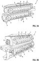
- shows a first view on an embodiment of the connector cavity assembly with two connector cavities;
- Fig. 3B
- shows a second view on the connector cavity assembly of
Figure 3A ; - Fig. 4
- shows a third embodiment of a connector cavity assembly;
- Fig. 5
- shows a second embodiment of a connector cavity assembly;
- Fig. 6
- shows a fourth embodiment of a connector cavity assembly;
- Fig. 7
- shows a fifth embodiment of a connector cavity assembly; and
- Fig. 8
- shows an embodiment of a medical device.
-
Figure 1 shows an embodiment of aconnector cavity 1 comprising adistal end element 2 at its distal end and aproximal end element 3 at its proximal end. Between thedistal end element 2 theproximal end element 3, a plurality of ring-shapedinsulation elements 4 made from silicone and alternatingmetal rings 5 each comprising a metal spring in their interior are positioned. The insulatingelements 4 act as spacer between the metal rings 5 and for electrically insulating two adjacent metal rings 5. The metal rings 5 act as electrode contacts. - The insulating
elements 4 are compressible. Thedistal end element 2 and theproximal end element 3 are non-elastic. If a pressure is exerted onto thedistal end element 2 and/or theproximal end element 3, the insulatingelements 4 are (slightly) compressed and sealingly about the adjacent metal rings 5. - The
connector cavity 1 is intended to receive a connector of at least one electrode or lead that is to be inserted into an interior space of theconnector cavity 1. - This can be seen from
Figure 2 representing a longitudinal section through theconnector cavity 1 ofFigure 1 . InFigure 2 and in the following figures the same numeral references are used for the same or similar elements. - It is apparent, that an
interior space 6 of theconnector cavity 1 has sufficient space for housing a connector comprising up to eight electrical contacts (each contact contacting ametal spring 50 of the respective metal ring 5). Thus, theconnector cavity 1 is suited to receive a connector of a lead having up to eight electrodes. - It is apparent from the depiction of
Figure 2 that theinsulation elements 4 electrically insulate two adjacent metal rings 5, whereas eachmetal ring 5 is in electrical contact with ametal spring 50 centrally arranged surrounding a longitudinal axis L of theconnector cavity 1. An electrical contact can be inserted along this longitudinal axis L into theinterior space 6 of theconnector cavity 1 since each insulatingelement 4 as well as eachmetal spring 50 comprises a central opening. -
Figure 3A shows an embodiment of theconnector cavity assembly 7 comprising two constructivelyidentical connector cavities 1 and aconnector cavity housing 8 housing bothconnector cavities 1. For better overview only some of the components of theconnector cavities 1 are marked with the respective numeral reference. Reference is made to the explanations given with respect toFigures 1 and 2 for explaining the structural details of theconnector cavities 1. - The
connector cavity housing 8 comprises two connector cavity receiving portions into which theconnector cavities 1 are inserted. Thereby, theconnector cavity housing 8 directly contacts the respectivedistal end elements 2 andproximal end element 3 of theconnector cavities 1. In doing so, it exerts a pressure onto thedistal end elements 2 and theproximal end elements 3 resulting in a pretension of theinsulation elements 4 between the conductive metal rings 5. The exerted pressure and thus the resulting pretension is defined by the spatial dimensions of the connector cavity receiving portion, i.e., the distance between a first end portion contacting thedistal end element 2 and a second end portion contacting theproximal end element 3 of therespective connector cavity 1. Since this distance is always the same due to a highly standardized manufacturing method (preferably by injection molding) the exerted pressure and the resulting pretension of theconnector cavities 1 is also always the same. Even if a high number ofconnector cavity assemblies 7 is manufactured, the variance between individualconnector cavity assemblies 7 is thus very small. -
Figure 3B shows theconnector cavity assembly 7 ofFigure 3A from the backside. Regarding the individual elements of theconnector cavity assembly 7, in particular theconnector cavity housing 8 and the insertedconnector cavities 1, reference is made to the explanations given with respect toFigure 3A and the preceding figures. Like inFigure 3A and also like in the following Figures, only some of the individual elements of theconnector cavity assembly 7 are marked with the respective numeral reference to allow a better overview. - In the depictions of
Figure 3A and Figure 3B , twospacers 9 can be seen that are provided at a lower side of theconnector cavity housing 8. Thesespacers 9 serve for guaranteeing a defined distance between theconnector cavity housing 8 and a body portion of a medical device onto which theconnector cavity housing 8 or theconnector cavity assembly 7, respectively, is to be applied.Figures 4 to 7 particularly illustrates the function of theaforementioned spacers 9. Preferably, thespacers 9 comprise a protruding portion, which is meant to be received by a matching opening or recess on a portion of the above mentioned body portion of the medical device. -
Figure 4 shows an embodiment of theconnector cavity assembly 7, wherein theconnector housing 8 comprises a holdingelement 10 that holds anantenna 11. Thereby, theantenna 11 is clipped onto the holdingelement 10. It can further be seen fromFigure 4 how theconnector cavity assembly 7 is to be placed abody portion 12 of a medical device. Thereby,electrical connectors 13 of thebody portion 12, particularly pins 13 extending through thefeedthrough 20 of thehousing 12 of a medical device, face the mountedconnector cavity assembly 7 and enable an electrical connection of individual components of theconnector cavity assembly 7 to thebody portion 12 of the medical device. Advantageously, the electrical connectors 13 (pins) of the body portion 12 (housing) are fixed to the respective wiring ribbons of theconnector cavity assembly 7 by soldering, brazing or welding. - The holding
element 10 enables a pre-assembly of theantenna 11 on theconnector cavity housing 8 so as to form part of theconnector cavity assembly 7. This facilitates a later assembly of the final medical device since theantenna 11 needs no longer be placed into a resin mold upon embedding theantenna 11 and theconnector cavities 1 as well as optionally further electrical elements in a resin. -
Figure 5 shows another embodiment of aconnector cavity assembly 7 already mounted to thebody portion 12 or housing of a medical device. Like the embodiments described with respect toFigure 4 , also the embodiment shown inFigure 5 comprises anantenna 11 held by a holdingelement 10 of theconnector cavity housing 8 of theconnector cavity assembly 7. Furthermore, twoconnector cavities 1 are inserted into respective connector cavity receiving portions of theconnector cavity housing 8. Additionally, a plurality offirst wiring ribbons 14 guided in guideways formed on theconnector cavity housing 8 is provided. Thesefirst wiring ribbons 14 contact the metal rings 5 of theupper connector cavity 1 and thus establish an electric contact between electronics housed in thebody portion 12 of the medical device and themetallic springs 50 arranged inside the metal rings 5, particularly via thepins 13 of thefeedthrough 20. Since theupper connector cavity 1 is arranged closer to that side oriented towards the front inFigure 5 , thefirst wiring ribbons 14 do not come into contact with any parts of thelower connector cavity 1, in particular not with any electrically conductive part of thelower connector cavity 1. -
Figure 6 shows another embodiment of theconnector cavity assembly 7 with aconnector cavity housing 8 and two insertedconnector cavities 1. Thereby, the view on this exemplary embodiment of theconnector cavity assembly 7 is from the opposite side than the view onto theconnector cavity assembly 7 ofFigure 5 . - In the embodiment shown in
Figure 6 , a plurality ofsecond wiring ribbons 15 is shown guided in guideways formed on theconnector cavity housing 8. Since thelower connector cavity 1 is closer to that side of theconnector cavity housing 8 that faces to the front inFigure 6 , thesecond wiring ribbons 15 can easily get in contact with thelower connector cavity 1 and thus establish an electric contact between electronics housed in thebody portion 12 or housing of the medical device and themetallic springs 50 arranged inside the metal rings 5. -
Figure 7 shows another embodiment of theconnector cavity assembly 7 with aconnector cavity housing 8 and two insertedconnector cavities 1. Besides theantenna 11 and thefirst wiring ribbons 14 already known from the preceding embodiments, this embodiment also comprises aninductive coil 16 for charging a medical device, theconnector cavity assembly 7 forms part of. Thereby, theconnector cavity housing 8 comprises four guidingpins 17 for guiding theinductive coil 16 as well as four holdingclips 18 for holding theconductive coil 16. - By providing these guiding
pins 17 it is particularly easy to bring theinductive coil 16 into the correct position on theconnector cavity housing 8. Furthermore, the holding clips 18 serve for a tight connection of theinductive coil 16 on theconnector cavity housing 8. - It would also be possible to provide holding
pins 17 and holdingclips 18 without additionally providing a holdingelement 10 for theantenna 11 and/or without providing guideways for thefirst wiring ribbons 14 that are all present in the embodiment ofFigure 7 . But a combination of these individual elements, i.e., a combination of the precedingly explained embodiments of theconnector cavity assembly 7 makes it particularly simple to combine different functionalities into the singleconnector cavity assembly 7 so as to further facilitate the manufacturing process of a medical device of which theconnector cavity 7 forms part of. - It is furthermore easily apparent that the embodiment shown in
Figure 6 , i.e., aconnector cavity assembly 7 making use of guideways forsecond wiring ribbons 15 can also be combined with some or all of the other embodiments. Then, both theupper connector cavity 1 and thelower connector cavity 1 can be easily contacted by first andsecond wiring ribbons -
Figure 8 shows aneurostimulator 19 serving as medical device. It comprises abody portion 12 and aheader portion 20. Theheader portion 20 comprises a resin into which aconnector cavity assembly 7, e.g., the embodiment shown inFigure 7 , with aninductive coil 16 is embedded. The resin of theheader portion 20 serves for sealing all embedded components with respect to an environment, i.e. with the respect to a body of the patient who carries theneurostimulator 19 as implantable device. - The
header portion 20 comprises two connectingports 21 through each of which a connector of an electrode can be inserted so as to reach the interior of therespective connector cavity 1. In doing so, an electrical contact between the neurostimulator 19 and a connected electrode (not shown inFigure 8 ) can be established.
Claims (15)
- Connector cavity assembly for a medical device, comprising- at least one connector cavity (1) comprising a plurality of electrically conductive electrode contacts (5) spaced apart from each other and a plurality of electrically insulating insulation elements (4), wherein the electrode contacts (5) and the insulation elements (4) are arranged alternatingly, and- a connector cavity housing (8),characterized
in that the at least one connector cavity (1) is removably arranged within the connector cavity housing (8), wherein the connector cavity housing (8) exerts a pretension on the at least one connector cavity (1) leading to a liquid-tight sealing between the insulation elements (4) and the electrode contacts (5). - Connector cavity assembly according to claim 1, characterized in that the at least one connector cavity (1) extends in a longitudinal direction from a proximal end to a distal end and comprises a proximal end element (3) positioned at the proximal end and a distal end element (2) positioned at the distal end.
- Connector cavity assembly according to claim 0, characterized in that the connector cavity housing (8) is in contact with the connector cavity (1) essentially or solely via the distal end element (2) and the proximal end element (3).
- Connector cavity assembly according to any of the preceding claims, characterized in that the connector cavity assembly (7) comprises at least two connector cavities (1) that are offset to each other in a longitudinal direction and/or in a transversal direction of the connector cavity housing (7).
- Connector cavity assembly according to any of the preceding claims, characterized in that the connector cavity housing (7) comprises at least one additional receiving portion (10) for receiving a further component (11, 14, 15, 16) of a medical device (19).
- Connector cavity assembly according to claim 0, characterized in that the additional receiving portion (10) enables an attachment of a further component (11, 14, 15, 16) of a medical device (19) by a latching connection.
- Connector cavity assembly according to any of the preceding claims, characterized in that the connector cavity assembly (7) comprises at least one of an antenna (11), a coil (16), and guideways for an external wiring.
- Connector cavity assembly according to any of the preceding claims, characterized in that the connector cavity housing (8) comprises at least one spacer (9) on its lower side that is intended to face a body portion (12) of a medical device (19) when the connector cavity housing (8) is part of a medical device (19).
- Medical device comprising a connector cavity assembly (7) according to any of the preceding claims.
- Medical device according to claim 0, characterized in that the connector cavity assembly (7) is embedded into a resin, wherein a connecting port (21) is formed in the resin so that an interior of the at least one connector cavity (1) of the connector cavity assembly (7) is accessible from outside the medical device (19).
- Medical device according to claim 0 or 0, characterized in that the medical device (19) is an implantable cardiac pacemaker, an implantable cardioverter defibrillator, or an implantable neurostimulator.
- Method for manufacturing a connector cavity assembly according to any of claims 1 to 0, comprising the following steps:a) providing a connector cavity housing (8),b1) assembling a connector cavity (1) by alternatingly placing electrically conductive electrode contacts (5) and electrically insulating insulation elements (4) into a pretensioning device, orb2) placing a pre-assembled connector cavity (1) comprising alternatingly positioned electrically conductive electrode contacts (5) and electrically insulating insulation elements (4) into a pretensioning device,c) exerting a pretension on the connector cavity (1) with the pretensioning device,d) transferring the pretensioned connector cavity (1) into the connector cavity housing (8),e) releasing and removing the pretensioning device, andf) allowing the connector cavity housing (8) to exert a pretension on the connector cavity (1).
- Method according to claim 0, characterized in that the step of assembling the connector cavity (1) or of placing a pre-assembled connector cavity (1) into the pretensioning device is performed without any mandrel being present in an interior space (6) of the connector cavity (1).
- Method according to claim 0 or 0, characterized in that the connector cavity housing (8) is a plastic component made by injection molding.
- Method for manufacturing a medical device according to any of claims 0 to 0, comprising the following steps:a) providing a connector cavity assembly (7) according to any of claims 1 to 0,b) placing the connector cavity assembly (7) on a body (12) of a medical device (19),c) establishing an electrical contact between at least one electrically conductive electrode contact (5) of the connector cavity assembly (7) and an electronics housed in the body (12) of the medical device (19),d) casting a hardenable resin around the connector cavity assembly (7).
Priority Applications (3)
| Application Number | Priority Date | Filing Date | Title |
|---|---|---|---|
| EP19174589.2A EP3739692B1 (en) | 2019-05-15 | 2019-05-15 | Connector cavity assembly for a medical device and manufacturing method |
| AU2020203036A AU2020203036A1 (en) | 2019-05-15 | 2020-05-07 | Connector cavity assembly for a medical device and manufacturing method |
| US16/871,415 US11318320B2 (en) | 2019-05-15 | 2020-05-11 | Connector cavity assembly for a medical device and manufacturing method |
Applications Claiming Priority (1)
| Application Number | Priority Date | Filing Date | Title |
|---|---|---|---|
| EP19174589.2A EP3739692B1 (en) | 2019-05-15 | 2019-05-15 | Connector cavity assembly for a medical device and manufacturing method |
Publications (2)
| Publication Number | Publication Date |
|---|---|
| EP3739692A1 true EP3739692A1 (en) | 2020-11-18 |
| EP3739692B1 EP3739692B1 (en) | 2024-02-28 |
Family
ID=66554236
Family Applications (1)
| Application Number | Title | Priority Date | Filing Date |
|---|---|---|---|
| EP19174589.2A Active EP3739692B1 (en) | 2019-05-15 | 2019-05-15 | Connector cavity assembly for a medical device and manufacturing method |
Country Status (3)
| Country | Link |
|---|---|
| US (1) | US11318320B2 (en) |
| EP (1) | EP3739692B1 (en) |
| AU (1) | AU2020203036A1 (en) |
Citations (1)
| Publication number | Priority date | Publication date | Assignee | Title |
|---|---|---|---|---|
| US8091226B2 (en) * | 2007-04-11 | 2012-01-10 | Bal Seal Engineering, Inc. | Integrated header connector system |
Family Cites Families (4)
| Publication number | Priority date | Publication date | Assignee | Title |
|---|---|---|---|---|
| US8215013B2 (en) * | 2008-04-11 | 2012-07-10 | Bal Seal Engineering, Inc. | Method for making a free standing axially compressed connector stack |
| US11139603B2 (en) * | 2017-10-03 | 2021-10-05 | Boston Scientific Neuromodulation Corporation | Connectors with spring contacts for electrical stimulation systems and methods of making and using same |
| US11040210B2 (en) * | 2018-04-02 | 2021-06-22 | Pacesetter, Inc. | All metal enclosed implantable medical device with external BLE antenna for RF telemetry |
| US11058882B2 (en) * | 2019-02-11 | 2021-07-13 | Medtronic, Inc. | Implantable medical devices having circuitry located adjacent to header-related structures |
-
2019
- 2019-05-15 EP EP19174589.2A patent/EP3739692B1/en active Active
-
2020
- 2020-05-07 AU AU2020203036A patent/AU2020203036A1/en not_active Abandoned
- 2020-05-11 US US16/871,415 patent/US11318320B2/en active Active
Patent Citations (1)
| Publication number | Priority date | Publication date | Assignee | Title |
|---|---|---|---|---|
| US8091226B2 (en) * | 2007-04-11 | 2012-01-10 | Bal Seal Engineering, Inc. | Integrated header connector system |
Non-Patent Citations (4)
| Title |
|---|
| CHEMICAL ABSTRACTS, Columbus, Ohio, US; abstract no. 25135-51-7 |
| CHEMICAL ABSTRACTS, Columbus, Ohio, US; abstract no. 25608-63-3 |
| CHEMICAL ABSTRACTS, Columbus, Ohio, US; abstract no. 29658-26-2 |
| CHEMICAL ABSTRACTS, Columbus, Ohio, US; abstract no. 9003-56-9 |
Also Published As
| Publication number | Publication date |
|---|---|
| AU2020203036A1 (en) | 2020-12-03 |
| US11318320B2 (en) | 2022-05-03 |
| US20200360700A1 (en) | 2020-11-19 |
| EP3739692B1 (en) | 2024-02-28 |
Similar Documents
| Publication | Publication Date | Title |
|---|---|---|
| US10886677B2 (en) | Distal connector assemblies for medical lead extensions | |
| US7537474B2 (en) | Lead receptacle and pin frame assembly | |
| EP2504500B1 (en) | Forming feedthroughs for hermetically sealed housings using two-material powder injection molding | |
| US7309262B2 (en) | Connector assembly for an implantable medical device and process for making | |
| US20090270961A1 (en) | Terminal housing for an electromedical implant | |
| EP3093927B1 (en) | Header for implantable pulse generator | |
| JP5587864B2 (en) | Connector cartridge laminate for power transfer | |
| US7654843B2 (en) | Connector assembly with internal seals and manufacturing method | |
| EP2950882B1 (en) | Lead connector with a premanufactured distal end and method of manufacture | |
| US6327502B1 (en) | Implantable stimulator housing with electrode connector | |
| CN109364372B (en) | Cover components, pulse generators, and implantable electrical stimulation systems | |
| WO2019229222A1 (en) | Motor housing module for a heart support system, and heart support system and method for mounting a heart support system | |
| US20040116976A1 (en) | Interconnect for implantable medical device header | |
| US20030069612A1 (en) | System and method for two-shot molding of thermoplastic materials | |
| US20100285697A1 (en) | Connector assembly for an implantable medical device and process for making | |
| US20090093855A1 (en) | Housing for a medical implant | |
| US9227049B2 (en) | Method of manufacturing electrical connection plug for a multipolar lead of an active implantable medical device | |
| CA2736204C (en) | Hyperboloid electrical connector assembly | |
| WO2007059374A2 (en) | Method for forming a connector assembly for use with an implantable medical device | |
| US11331502B2 (en) | Implantable medical leads and lead extensions having an encapsulation band | |
| US11318320B2 (en) | Connector cavity assembly for a medical device and manufacturing method | |
| EP1501599B1 (en) | Device in connection with pacers | |
| EP2162180A1 (en) | Medical implantable lead and method for manufacturing the same | |
| EP1295367A2 (en) | System and method for two-shot molding of thermoplastic materials | |
| CN113557054B (en) | Method for manufacturing a medical implant |
Legal Events
| Date | Code | Title | Description |
|---|---|---|---|
| PUAI | Public reference made under article 153(3) epc to a published international application that has entered the european phase |
Free format text: ORIGINAL CODE: 0009012 |
|
| STAA | Information on the status of an ep patent application or granted ep patent |
Free format text: STATUS: THE APPLICATION HAS BEEN PUBLISHED |
|
| AK | Designated contracting states |
Kind code of ref document: A1 Designated state(s): AL AT BE BG CH CY CZ DE DK EE ES FI FR GB GR HR HU IE IS IT LI LT LU LV MC MK MT NL NO PL PT RO RS SE SI SK SM TR |
|
| AX | Request for extension of the european patent |
Extension state: BA ME |
|
| STAA | Information on the status of an ep patent application or granted ep patent |
Free format text: STATUS: REQUEST FOR EXAMINATION WAS MADE |
|
| 17P | Request for examination filed |
Effective date: 20210518 |
|
| RBV | Designated contracting states (corrected) |
Designated state(s): AL AT BE BG CH CY CZ DE DK EE ES FI FR GB GR HR HU IE IS IT LI LT LU LV MC MK MT NL NO PL PT RO RS SE SI SK SM TR |
|
| STAA | Information on the status of an ep patent application or granted ep patent |
Free format text: STATUS: EXAMINATION IS IN PROGRESS |
|
| 17Q | First examination report despatched |
Effective date: 20220517 |
|
| GRAP | Despatch of communication of intention to grant a patent |
Free format text: ORIGINAL CODE: EPIDOSNIGR1 |
|
| STAA | Information on the status of an ep patent application or granted ep patent |
Free format text: STATUS: GRANT OF PATENT IS INTENDED |
|
| INTG | Intention to grant announced |
Effective date: 20230920 |
|
| GRAS | Grant fee paid |
Free format text: ORIGINAL CODE: EPIDOSNIGR3 |
|
| GRAA | (expected) grant |
Free format text: ORIGINAL CODE: 0009210 |
|
| STAA | Information on the status of an ep patent application or granted ep patent |
Free format text: STATUS: THE PATENT HAS BEEN GRANTED |
|
| AK | Designated contracting states |
Kind code of ref document: B1 Designated state(s): AL AT BE BG CH CY CZ DE DK EE ES FI FR GB GR HR HU IE IS IT LI LT LU LV MC MK MT NL NO PL PT RO RS SE SI SK SM TR |
|
| REG | Reference to a national code |
Ref country code: GB Ref legal event code: FG4D |
|
| REG | Reference to a national code |
Ref country code: CH Ref legal event code: EP |
|
| REG | Reference to a national code |
Ref country code: DE Ref legal event code: R096 Ref document number: 602019047187 Country of ref document: DE |
|
| REG | Reference to a national code |
Ref country code: IE Ref legal event code: FG4D |
|
| P01 | Opt-out of the competence of the unified patent court (upc) registered |
Effective date: 20240327 |
|
| REG | Reference to a national code |
Ref country code: LT Ref legal event code: MG9D |
|
| PG25 | Lapsed in a contracting state [announced via postgrant information from national office to epo] |
Ref country code: IS Free format text: LAPSE BECAUSE OF FAILURE TO SUBMIT A TRANSLATION OF THE DESCRIPTION OR TO PAY THE FEE WITHIN THE PRESCRIBED TIME-LIMIT Effective date: 20240628 |
|
| REG | Reference to a national code |
Ref country code: NL Ref legal event code: MP Effective date: 20240228 |
|
| PG25 | Lapsed in a contracting state [announced via postgrant information from national office to epo] |
Ref country code: LT Free format text: LAPSE BECAUSE OF FAILURE TO SUBMIT A TRANSLATION OF THE DESCRIPTION OR TO PAY THE FEE WITHIN THE PRESCRIBED TIME-LIMIT Effective date: 20240228 |
|
| PG25 | Lapsed in a contracting state [announced via postgrant information from national office to epo] |
Ref country code: GR Free format text: LAPSE BECAUSE OF FAILURE TO SUBMIT A TRANSLATION OF THE DESCRIPTION OR TO PAY THE FEE WITHIN THE PRESCRIBED TIME-LIMIT Effective date: 20240529 |
|
| PG25 | Lapsed in a contracting state [announced via postgrant information from national office to epo] |
Ref country code: RS Free format text: LAPSE BECAUSE OF FAILURE TO SUBMIT A TRANSLATION OF THE DESCRIPTION OR TO PAY THE FEE WITHIN THE PRESCRIBED TIME-LIMIT Effective date: 20240528 Ref country code: NL Free format text: LAPSE BECAUSE OF FAILURE TO SUBMIT A TRANSLATION OF THE DESCRIPTION OR TO PAY THE FEE WITHIN THE PRESCRIBED TIME-LIMIT Effective date: 20240228 Ref country code: HR Free format text: LAPSE BECAUSE OF FAILURE TO SUBMIT A TRANSLATION OF THE DESCRIPTION OR TO PAY THE FEE WITHIN THE PRESCRIBED TIME-LIMIT Effective date: 20240228 |
|
| PG25 | Lapsed in a contracting state [announced via postgrant information from national office to epo] |
Ref country code: ES Free format text: LAPSE BECAUSE OF FAILURE TO SUBMIT A TRANSLATION OF THE DESCRIPTION OR TO PAY THE FEE WITHIN THE PRESCRIBED TIME-LIMIT Effective date: 20240228 |
|
| PG25 | Lapsed in a contracting state [announced via postgrant information from national office to epo] |
Ref country code: RS Free format text: LAPSE BECAUSE OF FAILURE TO SUBMIT A TRANSLATION OF THE DESCRIPTION OR TO PAY THE FEE WITHIN THE PRESCRIBED TIME-LIMIT Effective date: 20240528 Ref country code: NO Free format text: LAPSE BECAUSE OF FAILURE TO SUBMIT A TRANSLATION OF THE DESCRIPTION OR TO PAY THE FEE WITHIN THE PRESCRIBED TIME-LIMIT Effective date: 20240528 Ref country code: NL Free format text: LAPSE BECAUSE OF FAILURE TO SUBMIT A TRANSLATION OF THE DESCRIPTION OR TO PAY THE FEE WITHIN THE PRESCRIBED TIME-LIMIT Effective date: 20240228 Ref country code: LT Free format text: LAPSE BECAUSE OF FAILURE TO SUBMIT A TRANSLATION OF THE DESCRIPTION OR TO PAY THE FEE WITHIN THE PRESCRIBED TIME-LIMIT Effective date: 20240228 Ref country code: IS Free format text: LAPSE BECAUSE OF FAILURE TO SUBMIT A TRANSLATION OF THE DESCRIPTION OR TO PAY THE FEE WITHIN THE PRESCRIBED TIME-LIMIT Effective date: 20240628 Ref country code: HR Free format text: LAPSE BECAUSE OF FAILURE TO SUBMIT A TRANSLATION OF THE DESCRIPTION OR TO PAY THE FEE WITHIN THE PRESCRIBED TIME-LIMIT Effective date: 20240228 Ref country code: GR Free format text: LAPSE BECAUSE OF FAILURE TO SUBMIT A TRANSLATION OF THE DESCRIPTION OR TO PAY THE FEE WITHIN THE PRESCRIBED TIME-LIMIT Effective date: 20240529 Ref country code: FI Free format text: LAPSE BECAUSE OF FAILURE TO SUBMIT A TRANSLATION OF THE DESCRIPTION OR TO PAY THE FEE WITHIN THE PRESCRIBED TIME-LIMIT Effective date: 20240228 Ref country code: ES Free format text: LAPSE BECAUSE OF FAILURE TO SUBMIT A TRANSLATION OF THE DESCRIPTION OR TO PAY THE FEE WITHIN THE PRESCRIBED TIME-LIMIT Effective date: 20240228 Ref country code: BG Free format text: LAPSE BECAUSE OF FAILURE TO SUBMIT A TRANSLATION OF THE DESCRIPTION OR TO PAY THE FEE WITHIN THE PRESCRIBED TIME-LIMIT Effective date: 20240228 |
|
| PG25 | Lapsed in a contracting state [announced via postgrant information from national office to epo] |
Ref country code: PL Free format text: LAPSE BECAUSE OF FAILURE TO SUBMIT A TRANSLATION OF THE DESCRIPTION OR TO PAY THE FEE WITHIN THE PRESCRIBED TIME-LIMIT Effective date: 20240228 Ref country code: PT Free format text: LAPSE BECAUSE OF FAILURE TO SUBMIT A TRANSLATION OF THE DESCRIPTION OR TO PAY THE FEE WITHIN THE PRESCRIBED TIME-LIMIT Effective date: 20240628 |
|
| REG | Reference to a national code |
Ref country code: AT Ref legal event code: MK05 Ref document number: 1662122 Country of ref document: AT Kind code of ref document: T Effective date: 20240228 |
|
| PG25 | Lapsed in a contracting state [announced via postgrant information from national office to epo] |
Ref country code: SE Free format text: LAPSE BECAUSE OF FAILURE TO SUBMIT A TRANSLATION OF THE DESCRIPTION OR TO PAY THE FEE WITHIN THE PRESCRIBED TIME-LIMIT Effective date: 20240228 Ref country code: PT Free format text: LAPSE BECAUSE OF FAILURE TO SUBMIT A TRANSLATION OF THE DESCRIPTION OR TO PAY THE FEE WITHIN THE PRESCRIBED TIME-LIMIT Effective date: 20240628 Ref country code: PL Free format text: LAPSE BECAUSE OF FAILURE TO SUBMIT A TRANSLATION OF THE DESCRIPTION OR TO PAY THE FEE WITHIN THE PRESCRIBED TIME-LIMIT Effective date: 20240228 Ref country code: LV Free format text: LAPSE BECAUSE OF FAILURE TO SUBMIT A TRANSLATION OF THE DESCRIPTION OR TO PAY THE FEE WITHIN THE PRESCRIBED TIME-LIMIT Effective date: 20240228 |
|
| PG25 | Lapsed in a contracting state [announced via postgrant information from national office to epo] |
Ref country code: DK Free format text: LAPSE BECAUSE OF FAILURE TO SUBMIT A TRANSLATION OF THE DESCRIPTION OR TO PAY THE FEE WITHIN THE PRESCRIBED TIME-LIMIT Effective date: 20240228 |
|
| PG25 | Lapsed in a contracting state [announced via postgrant information from national office to epo] |
Ref country code: SM Free format text: LAPSE BECAUSE OF FAILURE TO SUBMIT A TRANSLATION OF THE DESCRIPTION OR TO PAY THE FEE WITHIN THE PRESCRIBED TIME-LIMIT Effective date: 20240228 |
|
| PG25 | Lapsed in a contracting state [announced via postgrant information from national office to epo] |
Ref country code: EE Free format text: LAPSE BECAUSE OF FAILURE TO SUBMIT A TRANSLATION OF THE DESCRIPTION OR TO PAY THE FEE WITHIN THE PRESCRIBED TIME-LIMIT Effective date: 20240228 Ref country code: CZ Free format text: LAPSE BECAUSE OF FAILURE TO SUBMIT A TRANSLATION OF THE DESCRIPTION OR TO PAY THE FEE WITHIN THE PRESCRIBED TIME-LIMIT Effective date: 20240228 |
|
| PG25 | Lapsed in a contracting state [announced via postgrant information from national office to epo] |
Ref country code: AT Free format text: LAPSE BECAUSE OF FAILURE TO SUBMIT A TRANSLATION OF THE DESCRIPTION OR TO PAY THE FEE WITHIN THE PRESCRIBED TIME-LIMIT Effective date: 20240228 |
|
| PG25 | Lapsed in a contracting state [announced via postgrant information from national office to epo] |
Ref country code: SK Free format text: LAPSE BECAUSE OF FAILURE TO SUBMIT A TRANSLATION OF THE DESCRIPTION OR TO PAY THE FEE WITHIN THE PRESCRIBED TIME-LIMIT Effective date: 20240228 |
|
| PG25 | Lapsed in a contracting state [announced via postgrant information from national office to epo] |
Ref country code: SM Free format text: LAPSE BECAUSE OF FAILURE TO SUBMIT A TRANSLATION OF THE DESCRIPTION OR TO PAY THE FEE WITHIN THE PRESCRIBED TIME-LIMIT Effective date: 20240228 Ref country code: SK Free format text: LAPSE BECAUSE OF FAILURE TO SUBMIT A TRANSLATION OF THE DESCRIPTION OR TO PAY THE FEE WITHIN THE PRESCRIBED TIME-LIMIT Effective date: 20240228 Ref country code: RO Free format text: LAPSE BECAUSE OF FAILURE TO SUBMIT A TRANSLATION OF THE DESCRIPTION OR TO PAY THE FEE WITHIN THE PRESCRIBED TIME-LIMIT Effective date: 20240228 Ref country code: EE Free format text: LAPSE BECAUSE OF FAILURE TO SUBMIT A TRANSLATION OF THE DESCRIPTION OR TO PAY THE FEE WITHIN THE PRESCRIBED TIME-LIMIT Effective date: 20240228 Ref country code: DK Free format text: LAPSE BECAUSE OF FAILURE TO SUBMIT A TRANSLATION OF THE DESCRIPTION OR TO PAY THE FEE WITHIN THE PRESCRIBED TIME-LIMIT Effective date: 20240228 Ref country code: CZ Free format text: LAPSE BECAUSE OF FAILURE TO SUBMIT A TRANSLATION OF THE DESCRIPTION OR TO PAY THE FEE WITHIN THE PRESCRIBED TIME-LIMIT Effective date: 20240228 Ref country code: AT Free format text: LAPSE BECAUSE OF FAILURE TO SUBMIT A TRANSLATION OF THE DESCRIPTION OR TO PAY THE FEE WITHIN THE PRESCRIBED TIME-LIMIT Effective date: 20240228 |
|
| REG | Reference to a national code |
Ref country code: DE Ref legal event code: R097 Ref document number: 602019047187 Country of ref document: DE |
|
| PG25 | Lapsed in a contracting state [announced via postgrant information from national office to epo] |
Ref country code: IT Free format text: LAPSE BECAUSE OF FAILURE TO SUBMIT A TRANSLATION OF THE DESCRIPTION OR TO PAY THE FEE WITHIN THE PRESCRIBED TIME-LIMIT Effective date: 20240228 |
|
| REG | Reference to a national code |
Ref country code: CH Ref legal event code: PL |
|
| PG25 | Lapsed in a contracting state [announced via postgrant information from national office to epo] |
Ref country code: IT Free format text: LAPSE BECAUSE OF FAILURE TO SUBMIT A TRANSLATION OF THE DESCRIPTION OR TO PAY THE FEE WITHIN THE PRESCRIBED TIME-LIMIT Effective date: 20240228 |
|
| PLBE | No opposition filed within time limit |
Free format text: ORIGINAL CODE: 0009261 |
|
| STAA | Information on the status of an ep patent application or granted ep patent |
Free format text: STATUS: NO OPPOSITION FILED WITHIN TIME LIMIT |
|
| PG25 | Lapsed in a contracting state [announced via postgrant information from national office to epo] |
Ref country code: MC Free format text: LAPSE BECAUSE OF FAILURE TO SUBMIT A TRANSLATION OF THE DESCRIPTION OR TO PAY THE FEE WITHIN THE PRESCRIBED TIME-LIMIT Effective date: 20240228 |
|
| PG25 | Lapsed in a contracting state [announced via postgrant information from national office to epo] |
Ref country code: LU Free format text: LAPSE BECAUSE OF NON-PAYMENT OF DUE FEES Effective date: 20240515 |
|
| PG25 | Lapsed in a contracting state [announced via postgrant information from national office to epo] |
Ref country code: MC Free format text: LAPSE BECAUSE OF FAILURE TO SUBMIT A TRANSLATION OF THE DESCRIPTION OR TO PAY THE FEE WITHIN THE PRESCRIBED TIME-LIMIT Effective date: 20240228 Ref country code: LU Free format text: LAPSE BECAUSE OF NON-PAYMENT OF DUE FEES Effective date: 20240515 Ref country code: CH Free format text: LAPSE BECAUSE OF NON-PAYMENT OF DUE FEES Effective date: 20240531 |
|
| 26N | No opposition filed |
Effective date: 20241129 |
|
| REG | Reference to a national code |
Ref country code: BE Ref legal event code: MM Effective date: 20240531 |
|
| PG25 | Lapsed in a contracting state [announced via postgrant information from national office to epo] |
Ref country code: IE Free format text: LAPSE BECAUSE OF NON-PAYMENT OF DUE FEES Effective date: 20240515 |
|
| PG25 | Lapsed in a contracting state [announced via postgrant information from national office to epo] |
Ref country code: SI Free format text: LAPSE BECAUSE OF FAILURE TO SUBMIT A TRANSLATION OF THE DESCRIPTION OR TO PAY THE FEE WITHIN THE PRESCRIBED TIME-LIMIT Effective date: 20240228 Ref country code: BE Free format text: LAPSE BECAUSE OF NON-PAYMENT OF DUE FEES Effective date: 20240531 |
|
| PG25 | Lapsed in a contracting state [announced via postgrant information from national office to epo] |
Ref country code: CY Free format text: LAPSE BECAUSE OF FAILURE TO SUBMIT A TRANSLATION OF THE DESCRIPTION OR TO PAY THE FEE WITHIN THE PRESCRIBED TIME-LIMIT; INVALID AB INITIO Effective date: 20190515 |
|
| PG25 | Lapsed in a contracting state [announced via postgrant information from national office to epo] |
Ref country code: HU Free format text: LAPSE BECAUSE OF FAILURE TO SUBMIT A TRANSLATION OF THE DESCRIPTION OR TO PAY THE FEE WITHIN THE PRESCRIBED TIME-LIMIT; INVALID AB INITIO Effective date: 20190515 |
|
| PG25 | Lapsed in a contracting state [announced via postgrant information from national office to epo] |
Ref country code: TR Free format text: LAPSE BECAUSE OF FAILURE TO SUBMIT A TRANSLATION OF THE DESCRIPTION OR TO PAY THE FEE WITHIN THE PRESCRIBED TIME-LIMIT Effective date: 20240228 |
|
| PGFP | Annual fee paid to national office [announced via postgrant information from national office to epo] |
Ref country code: GB Payment date: 20260521 Year of fee payment: 8 |
|
| PGFP | Annual fee paid to national office [announced via postgrant information from national office to epo] |
Ref country code: DE Payment date: 20260520 Year of fee payment: 8 |
|
| PGFP | Annual fee paid to national office [announced via postgrant information from national office to epo] |
Ref country code: FR Payment date: 20260522 Year of fee payment: 8 |