EP3739398A1 - System and method for wind turbine multivariable control using state dependent quadratic regulator - Google Patents
System and method for wind turbine multivariable control using state dependent quadratic regulator Download PDFInfo
- Publication number
- EP3739398A1 EP3739398A1 EP20173269.0A EP20173269A EP3739398A1 EP 3739398 A1 EP3739398 A1 EP 3739398A1 EP 20173269 A EP20173269 A EP 20173269A EP 3739398 A1 EP3739398 A1 EP 3739398A1
- Authority
- EP
- European Patent Office
- Prior art keywords
- wind turbine
- model
- time
- linearization
- lqr
- Prior art date
- Legal status (The legal status is an assumption and is not a legal conclusion. Google has not performed a legal analysis and makes no representation as to the accuracy of the status listed.)
- Granted
Links
Images


Classifications
-
- G—PHYSICS
- G05—CONTROLLING; REGULATING
- G05B—CONTROL OR REGULATING SYSTEMS IN GENERAL; FUNCTIONAL ELEMENTS OF SUCH SYSTEMS; MONITORING OR TESTING ARRANGEMENTS FOR SUCH SYSTEMS OR ELEMENTS
- G05B13/00—Adaptive control systems, i.e. systems automatically adjusting themselves to have a performance which is optimum according to some preassigned criterion
- G05B13/02—Adaptive control systems, i.e. systems automatically adjusting themselves to have a performance which is optimum according to some preassigned criterion electric
- G05B13/04—Adaptive control systems, i.e. systems automatically adjusting themselves to have a performance which is optimum according to some preassigned criterion electric involving the use of models or simulators
- G05B13/042—Adaptive control systems, i.e. systems automatically adjusting themselves to have a performance which is optimum according to some preassigned criterion electric involving the use of models or simulators in which a parameter or coefficient is automatically adjusted to optimise the performance
-
- F—MECHANICAL ENGINEERING; LIGHTING; HEATING; WEAPONS; BLASTING
- F03—MACHINES OR ENGINES FOR LIQUIDS; WIND, SPRING, OR WEIGHT MOTORS; PRODUCING MECHANICAL POWER OR A REACTIVE PROPULSIVE THRUST, NOT OTHERWISE PROVIDED FOR
- F03D—WIND MOTORS
- F03D7/00—Controlling wind motors
- F03D7/02—Controlling wind motors the wind motors having rotation axis substantially parallel to the air flow entering the rotor
- F03D7/04—Automatic control; Regulation
- F03D7/042—Automatic control; Regulation by means of an electrical or electronic controller
- F03D7/043—Automatic control; Regulation by means of an electrical or electronic controller characterised by the type of control logic
- F03D7/045—Automatic control; Regulation by means of an electrical or electronic controller characterised by the type of control logic with model-based controls
-
- F—MECHANICAL ENGINEERING; LIGHTING; HEATING; WEAPONS; BLASTING
- F03—MACHINES OR ENGINES FOR LIQUIDS; WIND, SPRING, OR WEIGHT MOTORS; PRODUCING MECHANICAL POWER OR A REACTIVE PROPULSIVE THRUST, NOT OTHERWISE PROVIDED FOR
- F03D—WIND MOTORS
- F03D7/00—Controlling wind motors
- F03D7/02—Controlling wind motors the wind motors having rotation axis substantially parallel to the air flow entering the rotor
- F03D7/028—Controlling wind motors the wind motors having rotation axis substantially parallel to the air flow entering the rotor controlling wind motor output power
-
- G—PHYSICS
- G05—CONTROLLING; REGULATING
- G05B—CONTROL OR REGULATING SYSTEMS IN GENERAL; FUNCTIONAL ELEMENTS OF SUCH SYSTEMS; MONITORING OR TESTING ARRANGEMENTS FOR SUCH SYSTEMS OR ELEMENTS
- G05B13/00—Adaptive control systems, i.e. systems automatically adjusting themselves to have a performance which is optimum according to some preassigned criterion
- G05B13/02—Adaptive control systems, i.e. systems automatically adjusting themselves to have a performance which is optimum according to some preassigned criterion electric
- G05B13/0205—Adaptive control systems, i.e. systems automatically adjusting themselves to have a performance which is optimum according to some preassigned criterion electric not using a model or a simulator of the controlled system
-
- G—PHYSICS
- G05—CONTROLLING; REGULATING
- G05B—CONTROL OR REGULATING SYSTEMS IN GENERAL; FUNCTIONAL ELEMENTS OF SUCH SYSTEMS; MONITORING OR TESTING ARRANGEMENTS FOR SUCH SYSTEMS OR ELEMENTS
- G05B13/00—Adaptive control systems, i.e. systems automatically adjusting themselves to have a performance which is optimum according to some preassigned criterion
- G05B13/02—Adaptive control systems, i.e. systems automatically adjusting themselves to have a performance which is optimum according to some preassigned criterion electric
- G05B13/04—Adaptive control systems, i.e. systems automatically adjusting themselves to have a performance which is optimum according to some preassigned criterion electric involving the use of models or simulators
-
- G—PHYSICS
- G05—CONTROLLING; REGULATING
- G05B—CONTROL OR REGULATING SYSTEMS IN GENERAL; FUNCTIONAL ELEMENTS OF SUCH SYSTEMS; MONITORING OR TESTING ARRANGEMENTS FOR SUCH SYSTEMS OR ELEMENTS
- G05B13/00—Adaptive control systems, i.e. systems automatically adjusting themselves to have a performance which is optimum according to some preassigned criterion
- G05B13/02—Adaptive control systems, i.e. systems automatically adjusting themselves to have a performance which is optimum according to some preassigned criterion electric
- G05B13/04—Adaptive control systems, i.e. systems automatically adjusting themselves to have a performance which is optimum according to some preassigned criterion electric involving the use of models or simulators
- G05B13/041—Adaptive control systems, i.e. systems automatically adjusting themselves to have a performance which is optimum according to some preassigned criterion electric involving the use of models or simulators in which a variable is automatically adjusted to optimise the performance
-
- G—PHYSICS
- G06—COMPUTING OR CALCULATING; COUNTING
- G06F—ELECTRIC DIGITAL DATA PROCESSING
- G06F30/00—Computer-aided design [CAD]
- G06F30/20—Design optimisation, verification or simulation
-
- G—PHYSICS
- G06—COMPUTING OR CALCULATING; COUNTING
- G06N—COMPUTING ARRANGEMENTS BASED ON SPECIFIC COMPUTATIONAL MODELS
- G06N7/00—Computing arrangements based on specific mathematical models
-
- Y—GENERAL TAGGING OF NEW TECHNOLOGICAL DEVELOPMENTS; GENERAL TAGGING OF CROSS-SECTIONAL TECHNOLOGIES SPANNING OVER SEVERAL SECTIONS OF THE IPC; TECHNICAL SUBJECTS COVERED BY FORMER USPC CROSS-REFERENCE ART COLLECTIONS [XRACs] AND DIGESTS
- Y02—TECHNOLOGIES OR APPLICATIONS FOR MITIGATION OR ADAPTATION AGAINST CLIMATE CHANGE
- Y02E—REDUCTION OF GREENHOUSE GAS [GHG] EMISSIONS, RELATED TO ENERGY GENERATION, TRANSMISSION OR DISTRIBUTION
- Y02E10/00—Energy generation through renewable energy sources
- Y02E10/70—Wind energy
- Y02E10/72—Wind turbines with rotation axis in wind direction
Definitions
- Operational performance of a wind turbine generator is subject to external conditions such as wind speed, wind shear, and other environmental factors. These external conditions can have a direct impact on the blade pitch, turbine rotational velocity, and can introduce vibrations into the tower or the blades. These disturbances can alter the wind turbine power generation level, stability, efficiency, and other performance metrics.
- the wind turbine is a highly dynamic and coupled system with intertwined control design constraints and performance criteria.
- Conventional wind turbine controllers consist of multiple single input/single output (SISO) loops, with sometimes competing and contradicting design objectives.
- SISO single input/single output
- Each SISO can access a few shared actuators.
- This loss of control signal can often lead to underperforming operation and pitch constraint violations.
- Embodying systems and methods provide a systematic and unified method for control design of a wind turbine using a consolidated multivariable controller implementing a multiple input/multiple output (MIMO) control approach.
- MIMO multiple input/multiple output
- Use of a consolidated multivariable controller provides a simplified control architecture with increased performance over conventional approaches implementing SISO loops with multiple actuators.
- Embodiments determine control commands from the MIMO inputs by implementing an optimal linear multivariable State Dependent Quadratic Regulator (SDQR) control unit based on a state dependent Riccati approach.
- SDQR Linear Quadratic Regulator
- LQR Linear Quadratic Regulator
- DARE Discrete-time Algebraic Riccati Equation
- the time horizon can be selectable by a user.
- the SDQR control unit is formulated as an output-weighting regulator with additional weightings on control input rates and accelerations.
- a recursive Riccati solver may be used for computational efficiency.
- embodying wind turbine control systems can work with a prestored bank of linearized models scheduled in real-time; in other implementations embodying wind turbine control systems can work with a linear model computed using online linearization in real time (i.e., linearization occurs at time intervals during and responsive to operation of the wind turbine).
- the control system can consider a wide range of operational and performance constraints including structural loading (such as wind turbine tower and blade vibration constraints), actuator constraints (e.g., blade pitch angle and generator torque), and speed and power regulation or setpoint tracking performance specifications.
- Embodying wind turbine control systems implementing linear model bank scheduling are provided with a bank of linearized models prestored and scheduled in real-time (e.g., by wind speed and azimuth angle parameters). The current operating point is also scheduled at sampling time.
- Embodying wind turbine control systems implementing online model linearization derive an analytic linearization based on evaluating in real-time sampling points at a selectable interval based on the current operating point values for the wind turbine. This approach is useful when analytical form of linearization is available, and the embodying system includes a control unit with enough computational power to evaluate the model in real time.
- ⁇ are the wind turbine states (turbine degrees of freedom);
- u is the set of control inputs (e.g., individual blade pitch angles and generator torque);
- d are the disturbances (e.g., wind parameters (speed, shear, etc.);
- y are the model outputs, which may be a combination of measured outputs and other outputs selected for control.
- the state space matrices are time-varying and may depend on states and/or some parameters (e.g., some estimated wind parameters).
- ⁇ x ⁇ A ⁇ ⁇ ⁇ ⁇ x + B ⁇ ⁇ ⁇ ⁇ u + B d ⁇ ⁇ ⁇ ⁇ d
- azimuth angle is a model state and wind speed is an input disturbance parameter.
- the linearized models are discretized at each sampling time before being used by the LQR.
- an analytical discretization may be computed offline (for example, by symbolic computation methods) and prestored in the system to be evaluated in real-time.
- FIG. 1 schematically depicts a wind turbine control system architecture 100 in accordance with embodiments.
- FIG. 1 depicts control system 100 with a linear model bank scheduling implementation.
- SDQR control unit 110 includes a processor unit and a memory unit that can store executable instructions, which when executed by the processor unit cause the processor unit to perform a unified method for control design of a wind turbine in accordance with embodiments.
- the memory unit can provide the control processor with local cache memory.
- SDQR control unit 110 also includes linear model plant bank 115 for the wind turbine 154 (also "plant” herein).
- the plant bank 115 is precomputed and stored in the system.
- an estimate of the disturbance parameters 130 that are used in the state space matrices are needed-e.g., a wind speed estimate.
- the actuator dynamic model 124 (pitch and torque actuators) is augmented with the scheduled model 122 of the wind turbine and is used to compute the LQR gain at every sampling time.
- the SDQR control unit is a state feedback controller, meaning that it assumes the availability of the plant states either by direct measurement or through an observer such a Kalman filter.
- the LQR control unit 140 is formulated such that it generates control acceleration commands. This enables the state feedback controller to have weighting on the control signal rates and accelerations.
- the LQR cost function is shown below, in which Q, R, S and T are tuning matrices to be designed.
- the control acceleration commands undergo a double integration stage 142 to get the control commands. Since the LQR unit is designed upon a linearized model around an operating point, these control commands are essentially the perturbations around the current operating point.
- the LQR unit can regulate turbine speed and power around certain levels (LQR regulation) or it can receive power and speed set-points 132 to track (LQR servomechanism).
- K(t) is the time-varying LQR gain calculated by solving an algebraic Riccati equation for sampling time periods.
- the current operating point is also time-varying and is scheduled in a similar fashion as the state space matrices.
- the total control commands are computed by adding control perturbation commands to the current operating point. These commands are sent to the actuators, which passing the actuator dynamics 152, will actuate the plant 154.
- FIG. 2 schematically depicts the wind turbine control system architecture 100 in accordance with embodiments.
- FIG. 2 depicts control system 100 with a linear model bank scheduling implementation.
- Control system 100 performs a real-time evaluation of an analytical linearization model 215 that is computed and prestored offline; as opposed to storing a model bank 115 of precomputed linear models selected based on scheduling.
- the current operating point can be computed by evaluation of an analytical form as well.
- the actuator dynamic model 124 is augmented with online linearization 222 based on evaluating in real-time sampling points.
- the controller tuning parameters of the SDQR include the Q, R, S and T matrices as shown in (1).
- the tuning of the SDQR parameters can be done by a simulation-based approach or by an implicit model following approach.
- the controller is tuned using closed-loop simulations and performance evaluations, based on sensitivities and trial and error.
- the scalar parameters on the numerator of each diagonal elements are tuned through closed loop simulations.
- a priority order may be selected to achieve the right trade-off between competing criteria. For example, the following priority design method may be used:
- the evaluation criteria may be clustered into three categories: loads, performance (e.g., speed and power regulation/tracking) and control commands.
- loads e.g., speed and power regulation/tracking
- control commands e.g., speed and power regulation/tracking
- features such as maximum (e.g., extreme loads, power/speed overshoot) and variance may be evaluated for each simulation scenario, such as in (2).
- a desired closed-loop dynamic model is selected, and the controller is tuned to achieve the prescribed closed-loop dynamics.
- the desired closed-loop dynamics is specified for the augmented plant-actuator open-loop system. Note that the augmented plant 150 is always strictly proper, so no D matrix.
- the cost function may be defined over the error between the closed-loop dynamics of the regulated output and their desired dynamics (see below). The terms associated with control input (and its derivatives) weighting may also be added to the cost function as in (1).
- y is measurement data
- the desired dynamics may be prescribed as the desired damping and natural frequency of each degree of freedom.
- the optional weights Qz and Ru may be used for scaling or further fine tuning or may be chosen to be identity for simplicity.
- the weighing matrices S and T may be tuned using simulations as in the simulation-based approach.
- a d 0 I n ⁇ diag ⁇ i 2 ⁇ ⁇ diag 2 ⁇ i ⁇ i desired closed loop ⁇ i and ⁇ i for each mode
- the simulation-based tuning method is used if a desired closed-loop dynamic is not available and/or is hard to prescribe.
- a combination of both simulation-based and implicit model following approaches can also be used. For example, one could specify the closed-loop dynamics for certain degrees of freedoms and tune the rest experimentally.
- FIG. 3 depicts weighting matrices 300 generated using tuning methods in accordance with embodiments.
- Embodiments address the varying operating conditions and wind disturbances by computing the weighting matrices using, for example, either of the two aforementioned tuning methods.
- These weighting matrices can be considered as the nominal weights and adapted online as indicated in FIG. 3 .
- the weights wi are adaptively changing depending on the corresponding outputs distance to their limits, using inverse quadratic radial basis functions with a tuning parameter ⁇ .
- the weights on constrains that are far from their boundary limits can be relaxed and the weights of those constraints that are getting close to their boundary limits can be increased inverse of their distance to their boundaries.
- a simulation of the pitch command and the generator speed during a 1-year extreme operating gust with and without adaptive tuning was performed. The simulation demonstrated that adaptive tuning can prevent pitch rate violation, in the expense of 5 rpm increase in the speed, which is still well within its limit (1650 +- 10%).
- MPC provides a way to solve the optimal control problem in a receding time window. This is achieved by solving a finite time-horizon optimization, but only implementing the solution at current time step and then optimizing again, repeatedly.
- the main difference between MPC and LQR is that it solves the optimization problem in a finite horizon, and that it takes into account the time varying dynamics in future time window, which makes MPC have a better ability to anticipate future events and take control actions accordingly.
- the MPC approach relies upon a physics-based dynamic model to predict the change in the system along the prediction window.
- the nonlinear model is approximated with a time-varying linear affine model around a trajectory along the prediction window consisting of the system's inputs, states and outputs.
- Such a trajectory is generated from model-based simulation, based upon the current state value and predicted control actions from previous step. This requires an analytically linearized model and enough computational power to evaluate the model multiple times and solve the optimization problem in real time.
- Figure 4 depicts pseudocode for a multiple input/multiple output wind turbine control algorithm 400 in accordance with embodiments.
- the pseudocode illustrates the steps of how the linear time-varying model is obtained online, and how the optimization is built and solved to get the control action.
- the control algorithm 400 assumes the availability of the plant states and the knowledge of the disturbances to initialize the prediction, and that they can be achieved through an estimator such as a Kalman filter.
- Block 410 determines the current model state by executing a simulation solution using the model most recent prior time step to obtain a model for the next prediction horizon.
- Block 420 builds a quadratic programming problem by applying an unconstrained MPC for output tracking.
- Block 430 converts the dynamic optimization into a quadratic programming problem by solving a minimization problem.
- Block 440 solves the optimization problem.
- the formulation and method presented for the infinite horizon LQR can be adapted for finite horizon LQR.
- the finite horizon denomination comes from replacing the infinite horizon cost function ⁇ y t Qy + u t Ru + u ⁇ t S u ⁇ + u ⁇ t T u ⁇
- constraints can be incorporated by adding corresponding penalty terms in the cost function.
- One of the key advantages of using this approach instead of a formulation with explicit inequality constraints is that the solution can be obtained without expensive iterative algorithms and be computed in as described in algorithm 400.
- a computer program application stored in non-volatile memory or computer-readable medium may include code or executable program instructions that when executed may instruct and/or cause a controller or processor to perform methods discussed herein such as a unified method for control design of a wind turbine using a consolidated multivariable controller implementing a MIMO) control approach, as disclosed above.
- the computer-readable medium may be a non-transitory computer-readable media including all forms and types of memory and all computer-readable media except for a transitory, propagating signal.
- the non-volatile memory or computer-readable medium may be external memory.
- the wind turbine model including both an analytical linearization model and at least one precomputed linear model.
Landscapes
- Engineering & Computer Science (AREA)
- Physics & Mathematics (AREA)
- General Physics & Mathematics (AREA)
- Evolutionary Computation (AREA)
- Software Systems (AREA)
- Artificial Intelligence (AREA)
- General Engineering & Computer Science (AREA)
- Theoretical Computer Science (AREA)
- Automation & Control Theory (AREA)
- Medical Informatics (AREA)
- Computer Vision & Pattern Recognition (AREA)
- Health & Medical Sciences (AREA)
- Sustainable Development (AREA)
- Life Sciences & Earth Sciences (AREA)
- Mechanical Engineering (AREA)
- Combustion & Propulsion (AREA)
- Chemical & Material Sciences (AREA)
- Sustainable Energy (AREA)
- Mathematical Optimization (AREA)
- Computational Mathematics (AREA)
- Mathematical Analysis (AREA)
- Data Mining & Analysis (AREA)
- Mathematical Physics (AREA)
- Pure & Applied Mathematics (AREA)
- Computing Systems (AREA)
- Algebra (AREA)
- Computer Hardware Design (AREA)
- Geometry (AREA)
- Wind Motors (AREA)
Abstract
Description
- Operational performance of a wind turbine generator is subject to external conditions such as wind speed, wind shear, and other environmental factors. These external conditions can have a direct impact on the blade pitch, turbine rotational velocity, and can introduce vibrations into the tower or the blades. These disturbances can alter the wind turbine power generation level, stability, efficiency, and other performance metrics.
- The wind turbine is a highly dynamic and coupled system with intertwined control design constraints and performance criteria. Conventional wind turbine controllers consist of multiple single input/single output (SISO) loops, with sometimes competing and contradicting design objectives. Each SISO can access a few shared actuators. As a result, there is no guarantee that the control signal commanded by each individual SISO loop is materialized. This loss of control signal can often lead to underperforming operation and pitch constraint violations.
-
-
FIG. 1 schematically depicts a wind turbine control system architecture in accordance with embodiments, with linear model bank scheduling; -
FIG. 2 schematically depicts the wind turbine control system architecture ofFIG. 1 in accordance with embodiments, with online model linearization; -
FIG. 3 depicts weighting matrices generated using tuning methods in accordance with embodiments; and -
FIG. 4 depicts pseudocode for a multiple input/multiple output wind turbine control algorithm in accordance with embodiments. - Embodying systems and methods provide a systematic and unified method for control design of a wind turbine using a consolidated multivariable controller implementing a multiple input/multiple output (MIMO) control approach. Use of a consolidated multivariable controller provides a simplified control architecture with increased performance over conventional approaches implementing SISO loops with multiple actuators.
- Embodiments determine control commands from the MIMO inputs by implementing an optimal linear multivariable State Dependent Quadratic Regulator (SDQR) control unit based on a state dependent Riccati approach. At the core of the SDQR is a Linear Quadratic Regulator (LQR) whose gain is computed online at every sampling time through real-time solution of a Discrete-time Algebraic Riccati Equation (DARE). In accordance with embodiments, the time horizon can be selectable by a user.
- The SDQR control unit is formulated as an output-weighting regulator with additional weightings on control input rates and accelerations. A recursive Riccati solver may be used for computational efficiency. In some implementations embodying wind turbine control systems can work with a prestored bank of linearized models scheduled in real-time; in other implementations embodying wind turbine control systems can work with a linear model computed using online linearization in real time (i.e., linearization occurs at time intervals during and responsive to operation of the wind turbine). The control system can consider a wide range of operational and performance constraints including structural loading (such as wind turbine tower and blade vibration constraints), actuator constraints (e.g., blade pitch angle and generator torque), and speed and power regulation or setpoint tracking performance specifications.
- Embodying wind turbine control systems implementing linear model bank scheduling are provided with a bank of linearized models prestored and scheduled in real-time (e.g., by wind speed and azimuth angle parameters). The current operating point is also scheduled at sampling time. This approach uses a bank of linear models that are computed offline and stored in the system for real-time scheduling. The granularity of the bank is set by predetermined model accuracy and resolution. As an example, a linear model may be computed for every 10 degrees of azimuth angle (thus 36 models per revolution), for every 1 m/s of wind speed, for the wind speed range from 5 m/s to 25 m/s, resulting in 36*21 = 765 linear models. This approach is useful when there is enough memory available to store the bank.
- Embodying wind turbine control systems implementing online model linearization derive an analytic linearization based on evaluating in real-time sampling points at a selectable interval based on the current operating point values for the wind turbine. This approach is useful when analytical form of linearization is available, and the embodying system includes a control unit with enough computational power to evaluate the model in real time.
- In both cases, the linearized model has the following linear dynamic state space form:


- Where ẋ are the wind turbine states (turbine degrees of freedom); u is the set of control inputs (e.g., individual blade pitch angles and generator torque); d are the disturbances (e.g., wind parameters (speed, shear, etc.); and y are the model outputs, which may be a combination of measured outputs and other outputs selected for control. The state space matrices are time-varying and may depend on states and/or some parameters (e.g., some estimated wind parameters). For example, if the state space matrices are scheduled by azimuth angle and wind speed, the model turns into the following form:



- In this example, azimuth angle is a model state and wind speed is an input disturbance parameter.
- If the original nonlinear plant model of the wind turbine is developed in continuous-time-e.g., through physics-based modeling, then the linearized models are discretized at each sampling time before being used by the LQR. For the case of analytic linearization, an analytical discretization may be computed offline (for example, by symbolic computation methods) and prestored in the system to be evaluated in real-time.
-
Figure 1 schematically depicts a wind turbinecontrol system architecture 100 in accordance with embodiments.FIG. 1 depictscontrol system 100 with a linear model bank scheduling implementation.SDQR control unit 110 includes a processor unit and a memory unit that can store executable instructions, which when executed by the processor unit cause the processor unit to perform a unified method for control design of a wind turbine in accordance with embodiments. The memory unit can provide the control processor with local cache memory.SDQR control unit 110 also includes linearmodel plant bank 115 for the wind turbine 154 (also "plant" herein). Theplant bank 115 is precomputed and stored in the system. - In order to schedule the bank, an estimate of the
disturbance parameters 130 that are used in the state space matrices are needed-e.g., a wind speed estimate. The actuator dynamic model 124 (pitch and torque actuators) is augmented with the scheduledmodel 122 of the wind turbine and is used to compute the LQR gain at every sampling time. The SDQR control unit is a state feedback controller, meaning that it assumes the availability of the plant states either by direct measurement or through an observer such a Kalman filter. - The
LQR control unit 140 is formulated such that it generates control acceleration commands. This enables the state feedback controller to have weighting on the control signal rates and accelerations. The LQR cost function is shown below, in which Q, R, S and T are tuning matrices to be designed. - LQR Controller cost function:

- The control acceleration commands undergo a
double integration stage 142 to get the control commands. Since the LQR unit is designed upon a linearized model around an operating point, these control commands are essentially the perturbations around the current operating point. The LQR unit can regulate turbine speed and power around certain levels (LQR regulation) or it can receive power and speed set-points 132 to track (LQR servomechanism). - The control acceleration commands are calculated as the following:


- Where K(t) is the time-varying LQR gain calculated by solving an algebraic Riccati equation for sampling time periods. The current operating point is also time-varying and is scheduled in a similar fashion as the state space matrices. The total control commands are computed by adding control perturbation commands to the current operating point. These commands are sent to the actuators, which passing the
actuator dynamics 152, will actuate theplant 154. - If the true actuator dynamics is nonlinear, its linear approximation is used in the model used by the LQR unit. Unlike the Linear Parameter-Varying (LPV) and gain scheduling control conventional approaches in which a bank of controllers is computed offline and scheduled in real-time, embodiments compute a bank of models offline and schedule the model online.
-
Figure 2 schematically depicts the wind turbinecontrol system architecture 100 in accordance with embodiments.FIG. 2 depictscontrol system 100 with a linear model bank scheduling implementation.Control system 100 performs a real-time evaluation of ananalytical linearization model 215 that is computed and prestored offline; as opposed to storing amodel bank 115 of precomputed linear models selected based on scheduling. In some embodiments, the current operating point can be computed by evaluation of an analytical form as well. The actuatordynamic model 124 is augmented withonline linearization 222 based on evaluating in real-time sampling points. - The controller tuning parameters of the SDQR include the Q, R, S and T matrices as shown in (1). The tuning of the SDQR parameters can be done by a simulation-based approach or by an implicit model following approach.
- In the simulation-based approach, the controller is tuned using closed-loop simulations and performance evaluations, based on sensitivities and trial and error. In this approach the tuning matrices may be selected to be diagonal, with each diagonal element normalized to its maximum value (known from the system constraints), as follows:

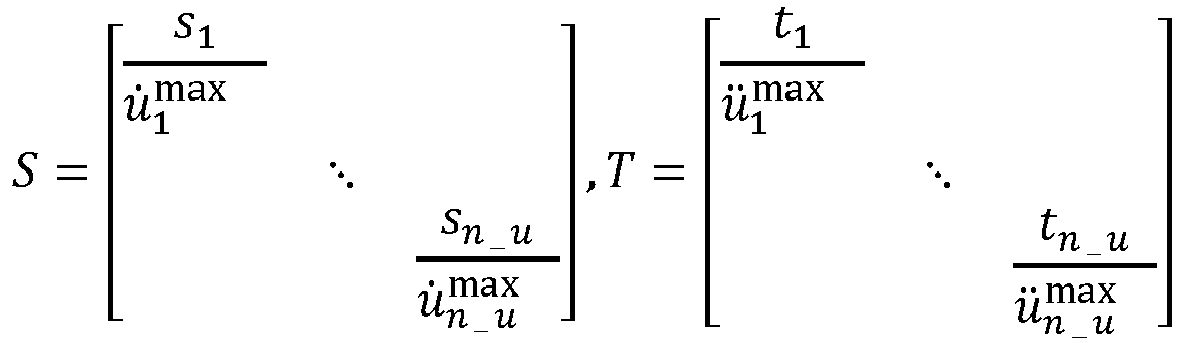
- The scalar parameters on the numerator of each diagonal elements are tuned through closed loop simulations. A priority order may be selected to achieve the right trade-off between competing criteria. For example, the following priority design method may be used:
- LQR with output weighting;
- Input magnitude, rate and acceleration weighting;
- Model is scheduled or analytically evaluated at every sampling point;
- DARE solved online at every sampling point;
- Output priority order: Generator Speed; Generator Power; Blade Flap; Tower fore-aft (FA); D, Q moments; Tower side-to-side (SS); and Blade Edge.
- To evaluate different performance criteria and assess the sensitivity of the design criteria to the tuning parameter, pareto charts may be used. To reduce the dimensionality of the pareto charts in the multivariable space, the evaluation criteria may be clustered into three categories: loads, performance (e.g., speed and power regulation/tracking) and control commands. For each category, features such as maximum (e.g., extreme loads, power/speed overshoot) and variance may be evaluated for each simulation scenario, such as in (2).

- Simulation scenarios were performed by a Design-of-Experiments (DoE) over the tuning parameters and other factors such as wind speeds, wind horizontal and vertical shears, and turbulence intensities. The simulation of stochastic wind profiles was repeated with different random seeds (e.g., a Monte Carlo simulation). Pareto tradeoffs were made between the normalized Tower Fore-Aft (Tower FA) load peak and standard deviation vs. those of the turbine power and speed. Embodying systems and methods simulation result showed that Tower FA extreme load can be reduced by about 4% with compromising of only less than 1% in power regulation performance, and less than 0.1 % of speed regulation performance.
- Under the implicit model following approach, a desired closed-loop dynamic model is selected, and the controller is tuned to achieve the prescribed closed-loop dynamics. The desired closed-loop dynamics is specified for the augmented plant-actuator open-loop system. Note that the
augmented plant 150 is always strictly proper, so no D matrix. The cost function may be defined over the error between the closed-loop dynamics of the regulated output and their desired dynamics (see below). The terms associated with control input (and its derivatives) weighting may also be added to the cost function as in (1).

- Where, y is measurement data;
- z are the regulated outputs;
- xd is the state vector of the desired dynamics;
- z d is the desired output response; and
- error (e) is minimized between the closed loop output response and the desired output response.
- The desired dynamics may be prescribed as the desired damping and natural frequency of each degree of freedom. This leads to an analytical form for the Q and R weighting matrices with structured weights simplifying the numerical solution of the Riccati equation. This provides a systematic approach for tuning, and significantly reduces the required effort required when tuning based on trial and error. The optional weights Qz and Ru may be used for scaling or further fine tuning or may be chosen to be identity for simplicity. The weighing matrices S and T may be tuned using simulations as in the simulation-based approach.
- Tuning parameters can include a predetermined damping and natural frequency for each mode; input weighting of Ru; and, optionally, Qz (e.g., Qz = diag(1/z_max)) for scaling. The weighting matrices are structured and computed analytically where ξi and ω i , i = 1, ..., n are the desired closed loop damping ratio and natural frequency of each mode:

- The simulation-based tuning method is used if a desired closed-loop dynamic is not available and/or is hard to prescribe. A combination of both simulation-based and implicit model following approaches can also be used. For example, one could specify the closed-loop dynamics for certain degrees of freedoms and tune the rest experimentally.
-
Figure 3 depictsweighting matrices 300 generated using tuning methods in accordance with embodiments. Embodiments address the varying operating conditions and wind disturbances by computing the weighting matrices using, for example, either of the two aforementioned tuning methods. These weighting matrices can be considered as the nominal weights and adapted online as indicated inFIG. 3 . The weights wi are adaptively changing depending on the corresponding outputs distance to their limits, using inverse quadratic radial basis functions with a tuning parameter γ. - In accordance with adaptive tuning, the weights on constrains that are far from their boundary limits can be relaxed and the weights of those constraints that are getting close to their boundary limits can be increased inverse of their distance to their boundaries. As an example, a simulation of the pitch command and the generator speed during a 1-year extreme operating gust with and without adaptive tuning was performed. The simulation demonstrated that adaptive tuning can prevent pitch rate violation, in the expense of 5 rpm increase in the speed, which is still well within its limit (1650 +- 10%).
- (MPC) provides a way to solve the optimal control problem in a receding time window. This is achieved by solving a finite time-horizon optimization, but only implementing the solution at current time step and then optimizing again, repeatedly. The main difference between MPC and LQR is that it solves the optimization problem in a finite horizon, and that it takes into account the time varying dynamics in future time window, which makes MPC have a better ability to anticipate future events and take control actions accordingly.
- The MPC approach relies upon a physics-based dynamic model to predict the change in the system along the prediction window. For the sake of computational simplification, the nonlinear model is approximated with a time-varying linear affine model around a trajectory along the prediction window consisting of the system's inputs, states and outputs.
- Such a trajectory is generated from model-based simulation, based upon the current state value and predicted control actions from previous step. This requires an analytically linearized model and enough computational power to evaluate the model multiple times and solve the optimization problem in real time.
-
Figure 4 depicts pseudocode for a multiple input/multiple output windturbine control algorithm 400 in accordance with embodiments. The pseudocode illustrates the steps of how the linear time-varying model is obtained online, and how the optimization is built and solved to get the control action. In addition, thecontrol algorithm 400 assumes the availability of the plant states and the knowledge of the disturbances to initialize the prediction, and that they can be achieved through an estimator such as a Kalman filter. -
Block 410 determines the current model state by executing a simulation solution using the model most recent prior time step to obtain a model for the next prediction horizon.Block 420 builds a quadratic programming problem by applying an unconstrained MPC for output tracking.Block 430 converts the dynamic optimization into a quadratic programming problem by solving a minimization problem.Block 440 solves the optimization problem. - The formulation and method presented for the infinite horizon LQR can be adapted for finite horizon LQR. The finite horizon denomination comes from replacing the infinite horizon cost function

- by a finite horizon counterpart, which can adopt the following form
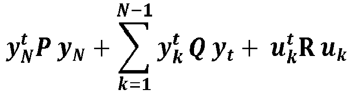
- This formulation has important practical implications because it considers the behavior only in the immediate prediction horizon and can be very effective to handle the behavior of the turbine in the future few seconds of operations. The approach using this cost function is also known as unconstrained model predictive control. The calculation of the associated control action (described in
FIG. 4 ), differs from the Riccati approach used for the inifinite horizon LQR. However, the methods for control tuning, selection of the weight matrices are applicable to this case. - Using the finite horizon LQR, constraints can be incorporated by adding corresponding penalty terms in the cost function. One of the key advantages of using this approach instead of a formulation with explicit inequality constraints is that the solution can be obtained without expensive iterative algorithms and be computed in as described in
algorithm 400. - In accordance with some embodiments, a computer program application stored in non-volatile memory or computer-readable medium (e.g., register memory, processor cache, RAM, ROM, hard drive, flash memory, CD ROM, magnetic media, etc.) may include code or executable program instructions that when executed may instruct and/or cause a controller or processor to perform methods discussed herein such as a unified method for control design of a wind turbine using a consolidated multivariable controller implementing a MIMO) control approach, as disclosed above.
- The computer-readable medium may be a non-transitory computer-readable media including all forms and types of memory and all computer-readable media except for a transitory, propagating signal. In one implementation, the non-volatile memory or computer-readable medium may be external memory.
- Furthermore, embodiments according to the following clauses are disclosed herein.
- 1. A system for wind turbine control, the system comprising:
- state dependent quadratic regulator (SDQR) control unit including a processor unit and a memory unit, the memory unit containing executable instructions;
- a linear quadratic regulator (LQR) configured to generate control acceleration commands for wind turbine speed and wind turbine power regulation;
- an actuator dynamic model configured to compute a gain value for the LQR at predetermined sampling intervals; and
- a wind turbine model to augment the actuator dynamic model.
- 2. The system of
clause 1, the actuator dynamic model configured to model pitch and torque actuators of the wind turbine. - 3. The system of
clause 1, the actuator dynamic model configured to apply a discrete-time algebraic Riccati equation linear quadratic regulator to compute the gain value in real-time. - 4. The system of
clause 1, the LQR configured to regulate the wind turbine speed and the wind turbine power in a range around certain levels or at set-points received as input to the control unit. - 5. The system of
clause 1, including, the wind turbine model including an analytical linearization model and at least one precomputed linear model. - 6. The system of clause 5, including the precomputed linear model selected from a model bank of precomputed linear models, the selection based on a real-time scheduling operation.
- 7. The system of clause 6, the scheduling operation based on an estimate of disturbance parameters influencing the wind turbine at about the time of scheduling.
- 8. The system of clause 5, including the analytical linearization model computed using an online linearization operation in real-time at time intervals during operation of the wind turbine, the online linearization based on the current operating point values for the wind turbine present at about the time of linearization.
- 9. A method of generating wind turbine control commands, the method comprising:
- augmenting an actuator dynamic model by employing a wind turbine model;
- computing a gain value for a linear quadratic regulator (LQR) in real-time at predetermined sampling intervals by the actuator dynamic model;
- generating control acceleration commands for wind turbine speed and wind turbine power regulation by the LQR; and
- a state feedback controller weighting the control acceleration commands by applying a plant bank model.
- 10. The method of clause 9, the gain value computation augmented by modeling pitch and torque actuators of the wind turbine.
- 11. The method of clause 9, applying a discrete-time algebraic Riccati equation linear quadratic regulator to compute the gain value in real-time.
- 12. The method of clause 9, regulating the wind turbine speed and the wind turbine power in a range around certain levels or at set-points received as input to the control unit.
- 13. The method of clause 9, the wind turbine model including an analytical linearization model and at least one precomputed linear model.
- 14. The method of clause 13, including selecting the precomputed linear model from a model bank of precomputed linear models, the selection based on a real-time scheduling operation.
- 15. The method of clause 14, including basing the scheduling operation on an estimate of disturbance parameters influencing the wind turbine at about the time of scheduling.
- 16. The method of clause 13, including computing the analytical linearization model using an online linearization operation in real-time at time intervals during operation of the wind turbine, the online linearization based on the current operating point values for the wind turbine present at about the time of linearization.
- 17. The method of clause 9, including tuning parameters of the LQR by performing one of an implicit model following approach and a simulation-based approach.
- 18. The method of clause 17, the implicit model following approach including:
- selecting a desired closed-loop dynamic model; and
- tuning the LQR to achieve the prescribed closed-loop dynamics.
- 19. The method of clause 17, the simulation-based approach including tuning the LQR using closed-loop simulations and performance evaluations, the simulations and evaluations based on sensitivities and trial and error.
- 20. A system comprising:
- a wind turbine including at least one pitch actuator, a torque actuator, and a control system, the control system in communication with the at least one pitch actuator and the torque actuator;
- the control system including:
- a state dependent quadratic regulator (SDQR) control unit including a processor unit and a memory unit, the memory unit containing executable instructions;
- a linear quadratic regulator (LQR) configured to generate control acceleration commands for wind turbine speed and wind turbine power regulation, the LQR implementing unconstrained model predictive control by generating the control acceleration commands for a finite horizon that accounts for time varying dynamics in a future time window;
- an actuator dynamic model configured to compute a gain value for the LQR at predetermined sampling intervals; and
- a wind turbine model to augment the actuator dynamic model, the wind turbine model including both an analytical linearization model and at least one precomputed linear model.
- Although specific hardware and methods have been described herein, note that any number of other configurations may be provided in accordance with embodiments of the invention. Thus, while there have been shown, described, and pointed out fundamental novel features of the invention, it will be understood that various omissions, substitutions, and changes in the form and details of the illustrated embodiments, and in their operation, may be made by those skilled in the art without departing from the spirit and scope of the invention. Substitutions of elements from one embodiment to another are also fully intended and contemplated. The invention is defined solely with regard to the claims appended hereto, and equivalents of the recitations therein.
Claims (15)
- A system (100) for wind turbine control, the system comprising:state dependent quadratic regulator (SDQR) control unit (110) including a processor unit and a memory unit, the memory unit containing executable instructions;a linear quadratic regulator (LQR) (140) configured to generate control acceleration commands for wind turbine speed and wind turbine power regulation;an actuator dynamic model (124) configured to compute a gain value for the LQR at predetermined sampling intervals; anda wind turbine model (122, 215) to augment the actuator dynamic model.
- The system of claim 1, the actuator dynamic model configured to apply a discrete-time algebraic Riccati equation linear quadratic regulator to compute the gain value in real-time.
- The system of claims 1-2, the LQR configured to regulate the wind turbine speed and the wind turbine power in a range around certain levels or at set-points (132) received as input to the control unit.
- The system of any of the preceding claims, including, the wind turbine model including an analytical linearization model (215) and at least one precomputed linear model (122).
- The system of claim 4, including:the precomputed linear model selected from a model bank of precomputed linear models;the selection based on a real-time scheduling operation; andthe scheduling operation based on an estimate of disturbance parameters (130) influencing the wind turbine at about the time of scheduling.
- The system of claim 4, including the analytical linearization model computed using an online linearization operation in real-time at time intervals during operation of the wind turbine, the online linearization based on the current operating point values for the wind turbine present at about the time of linearization.
- A method of generating wind turbine control commands, the method comprising:augmenting an actuator dynamic model (124) by employing a wind turbine model (122, 215);computing a gain value for a linear quadratic regulator (LQR) (140) in real-time at predetermined sampling intervals by the actuator dynamic model;generating control acceleration commands for wind turbine speed and wind turbine power regulation by the LQR; anda state feedback controller weighting the control acceleration commands by applying a plant bank model (115).
- The method of claim 7, including augmenting the gain value computation by modeling pitch and torque actuators of the wind turbine.
- The method of claims 7-8, applying a discrete-time algebraic Riccati equation linear quadratic regulator to compute the gain value in real-time.
- The method of claims 7-9, regulating the wind turbine speed and the wind turbine power in a range around certain levels or at set-points (132) received as input to the control unit.
- The method of claims 7-10, the wind turbine model including an analytical linearization model (215) and at least one precomputed linear model (115).
- The method of claim 11, including:selecting the precomputed linear model from a model bank of precomputed linear models;the selection based on a real-time scheduling operation; andbasing the scheduling operation on an estimate of disturbance parameters influencing the wind turbine at about the time of scheduling.
- The method of claim 11, including computing the analytical linearization model using an online linearization operation in real-time at time intervals during operation of the wind turbine, the online linearization based on the current operating point values for the wind turbine present at about the time of linearization.
- The method of claims 7-13, including:
tuning parameters of the LQR by performing an implicit model following approach, the implicit model following approach including:selecting a desired closed-loop dynamic model; andtuning the LQR to achieve the prescribed closed-loop dynamics. - The method of claims 7-14, including:
tuning parameters of the LQR by performing a simulation-based approach, the simulation-based approach including:
tuning the LQR using closed-loop simulations and performance evaluations, the simulations and evaluations based on sensitivities and trial and error.
Applications Claiming Priority (1)
| Application Number | Priority Date | Filing Date | Title |
|---|---|---|---|
| US16/414,484 US11125211B2 (en) | 2019-05-16 | 2019-05-16 | System and method for wind turbine multivariable control using state dependent quadratic regulator |
Publications (2)
| Publication Number | Publication Date |
|---|---|
| EP3739398A1 true EP3739398A1 (en) | 2020-11-18 |
| EP3739398B1 EP3739398B1 (en) | 2022-05-04 |
Family
ID=70613654
Family Applications (1)
| Application Number | Title | Priority Date | Filing Date |
|---|---|---|---|
| EP20173269.0A Active EP3739398B1 (en) | 2019-05-16 | 2020-05-06 | System and method for wind turbine multivariable control using state dependent quadratic regulator |
Country Status (4)
| Country | Link |
|---|---|
| US (1) | US11125211B2 (en) |
| EP (1) | EP3739398B1 (en) |
| DK (1) | DK3739398T3 (en) |
| ES (1) | ES2927991T3 (en) |
Families Citing this family (4)
| Publication number | Priority date | Publication date | Assignee | Title |
|---|---|---|---|---|
| JP7003623B2 (en) * | 2017-12-15 | 2022-01-20 | オムロン株式会社 | Control system |
| ES2875674B2 (en) * | 2020-05-07 | 2022-03-21 | Univ Del Pais Vasco / Euskal Herriko Unibertsitatea | Model-based predictive control method for structural load reduction in wind turbines, and turbine configured to apply this method |
| US20220319257A1 (en) * | 2021-03-31 | 2022-10-06 | Beta Air, Llc | Aircraft motion observer configured for use in electric aircraft |
| US12516655B2 (en) * | 2022-10-20 | 2026-01-06 | The Regents Of The University Of Colorado, A Body Corporate | Robust multi-input multi-output control of floating offshore wind turbines |
Family Cites Families (14)
| Publication number | Priority date | Publication date | Assignee | Title |
|---|---|---|---|---|
| US6244536B1 (en) | 1997-11-26 | 2001-06-12 | The United States Of America As Represented By The Secretary Of The Air Force | Air to air homing missile guidance |
| DE10017600A1 (en) | 2000-04-08 | 2001-10-11 | Bodenseewerk Geraetetech | Flight regulator for aircraft uses algorithm based upon real time solution of optimization equation to determine optimum control parameter based upon state vector and control vector |
| EP1710654B1 (en) | 2005-04-08 | 2009-03-18 | Ford Global Technologies, LLC | Method and system for active vibration isolation in automotive vehicles |
| US20070068210A1 (en) | 2005-09-29 | 2007-03-29 | University Of Pittsburgh - Of The Commonwealth System Of Higher Education | System for controlling a rolling mill and method of controlling a rolling mill |
| US7363094B2 (en) | 2006-01-09 | 2008-04-22 | General Electric Company | Multivariable controller design method for multiple input/outputs systems with multiple input/output constraints |
| EP1911968A1 (en) | 2006-10-10 | 2008-04-16 | Ecotecnia Energias Renovables S.L. | Control system for a wind turbine and method of controlling said wind turbine |
| US7883317B2 (en) | 2007-02-02 | 2011-02-08 | General Electric Company | Method for optimizing the operation of a wind turbine |
| US7772713B2 (en) | 2009-09-30 | 2010-08-10 | General Electric Company | Method and system for controlling a wind turbine |
| US9058028B2 (en) | 2011-04-29 | 2015-06-16 | Georgia Tech Research Corporation | Systems and methods for parameter dependent riccati equation approaches to adaptive control |
| CN102410138B (en) | 2011-08-24 | 2013-09-04 | 国电联合动力技术有限公司 | Method for acquiring optimal control input of wind generating set |
| US20130302161A1 (en) | 2012-05-08 | 2013-11-14 | Arne Koerber | Controller of wind turbine and wind turbine |
| US9644608B2 (en) | 2012-12-24 | 2017-05-09 | General Electric Company | Method and system for shutting down a wind turbine |
| US9366230B2 (en) | 2013-03-14 | 2016-06-14 | General Electric Company | System and method for reducing loads acting on a wind turbine in response to transient wind conditions |
| JP6604939B2 (en) * | 2013-03-15 | 2019-11-13 | ユナイテッド テクノロジーズ コーポレイション | Control system, control method and gas turbine engine |
-
2019
- 2019-05-16 US US16/414,484 patent/US11125211B2/en active Active
-
2020
- 2020-05-06 ES ES20173269T patent/ES2927991T3/en active Active
- 2020-05-06 EP EP20173269.0A patent/EP3739398B1/en active Active
- 2020-05-06 DK DK20173269.0T patent/DK3739398T3/en active
Non-Patent Citations (2)
| Title |
|---|
| HEER FLAVIO ET AL: "Model based power optimisation of wind farms", 2014 EUROPEAN CONTROL CONFERENCE (ECC), EUCA, 24 June 2014 (2014-06-24), pages 1145 - 1150, XP032623546, ISBN: 978-3-9524269-1-3, [retrieved on 20140722], DOI: 10.1109/ECC.2014.6862365 * |
| PARROTT EDWARD ET AL: "A robust adaptive control scheme for under-actuated non-linear systems", 2018 ANNUAL IEEE INTERNATIONAL SYSTEMS CONFERENCE (SYSCON), IEEE, 23 April 2018 (2018-04-23), pages 1 - 5, XP033352653, DOI: 10.1109/SYSCON.2018.8369523 * |
Also Published As
| Publication number | Publication date |
|---|---|
| ES2927991T3 (en) | 2022-11-14 |
| DK3739398T3 (en) | 2022-08-08 |
| EP3739398B1 (en) | 2022-05-04 |
| US11125211B2 (en) | 2021-09-21 |
| US20200362819A1 (en) | 2020-11-19 |
Similar Documents
| Publication | Publication Date | Title |
|---|---|---|
| EP3739398B1 (en) | System and method for wind turbine multivariable control using state dependent quadratic regulator | |
| Petrović et al. | Wind turbine envelope protection control over the full wind speed range | |
| Moon et al. | Step-response model development for dynamic matrix control of a drum-type boiler–turbine system | |
| Guo et al. | PID controller design for output PDFs of stochastic systems using linear matrix inequalities | |
| US11840224B2 (en) | Apparatus and method for control with data-driven model adaptation | |
| Hoagg et al. | Retrospective cost model reference adaptive control for nonminimum-phase systems | |
| US20070168057A1 (en) | Multi-objective predictive process optimization with concurrent process simulation | |
| US10048658B2 (en) | Information processing device, predictive control method, and recording medium | |
| Mate et al. | Simultaneous tuning of multiple PID controllers for multivariable systems using deep reinforcement learning | |
| Wang et al. | A novel adaptive model predictive frequency control using unscented Kalman filter | |
| Velasco et al. | Optimal-sampling-inspired self-triggered control | |
| Afonso et al. | Infeasibility handling in constrained MPC | |
| Bernardi et al. | Adaptive predictive control for industrial processes | |
| Wen et al. | Implicit generalized predictive control-based fractional-order PID strategy for BTTGU regulation system | |
| Homaeinezhad et al. | Addressing asymptotic stability of tracking control in nonlinear systems subjected to embedded unscented Kalman filter dynamics under actuator saturation | |
| Deeb et al. | Hierarchical Multi-objective Control of Nonlinear Systems with Dynamical Input Constraints | |
| Yang et al. | Performance evaluation of direct heuristic dynamic programming using control-theoretic measures | |
| Warren et al. | Improved output constraint-handling for MPC with disturbance uncertainty | |
| Wu et al. | Receding horizon iterative learning control for continuously operated systems | |
| Amirmojahedi et al. | Application of optimized polynomial controllers based on Bayesian optimization and weight matrix adjustment | |
| Parry | Predictive Control for Linear and Nonlinear Systems Subject to Exogenous Disturbances | |
| Stoica et al. | Off-line robustification of model predictive control for uncertain multivariable systems | |
| Durand et al. | Stiction compensation via model predictive control | |
| Li et al. | Robust Reference Governor for Implicit Systems Using the Metric Regularity | |
| Zhao et al. | Incremental Q-Learning for Data-Driven Adaptive Critic Control of Wastewater Treatment Processes With State Constraints |
Legal Events
| Date | Code | Title | Description |
|---|---|---|---|
| PUAI | Public reference made under article 153(3) epc to a published international application that has entered the european phase |
Free format text: ORIGINAL CODE: 0009012 |
|
| STAA | Information on the status of an ep patent application or granted ep patent |
Free format text: STATUS: THE APPLICATION HAS BEEN PUBLISHED |
|
| AK | Designated contracting states |
Kind code of ref document: A1 Designated state(s): AL AT BE BG CH CY CZ DE DK EE ES FI FR GB GR HR HU IE IS IT LI LT LU LV MC MK MT NL NO PL PT RO RS SE SI SK SM TR |
|
| AX | Request for extension of the european patent |
Extension state: BA ME |
|
| STAA | Information on the status of an ep patent application or granted ep patent |
Free format text: STATUS: REQUEST FOR EXAMINATION WAS MADE |
|
| 17P | Request for examination filed |
Effective date: 20210422 |
|
| RBV | Designated contracting states (corrected) |
Designated state(s): AL AT BE BG CH CY CZ DE DK EE ES FI FR GB GR HR HU IE IS IT LI LT LU LV MC MK MT NL NO PL PT RO RS SE SI SK SM TR |
|
| GRAP | Despatch of communication of intention to grant a patent |
Free format text: ORIGINAL CODE: EPIDOSNIGR1 |
|
| STAA | Information on the status of an ep patent application or granted ep patent |
Free format text: STATUS: GRANT OF PATENT IS INTENDED |
|
| INTG | Intention to grant announced |
Effective date: 20211123 |
|
| GRAS | Grant fee paid |
Free format text: ORIGINAL CODE: EPIDOSNIGR3 |
|
| GRAA | (expected) grant |
Free format text: ORIGINAL CODE: 0009210 |
|
| STAA | Information on the status of an ep patent application or granted ep patent |
Free format text: STATUS: THE PATENT HAS BEEN GRANTED |
|
| AK | Designated contracting states |
Kind code of ref document: B1 Designated state(s): AL AT BE BG CH CY CZ DE DK EE ES FI FR GB GR HR HU IE IS IT LI LT LU LV MC MK MT NL NO PL PT RO RS SE SI SK SM TR |
|
| REG | Reference to a national code |
Ref country code: GB Ref legal event code: FG4D |
|
| REG | Reference to a national code |
Ref country code: CH Ref legal event code: EP |
|
| REG | Reference to a national code |
Ref country code: AT Ref legal event code: REF Ref document number: 1489734 Country of ref document: AT Kind code of ref document: T Effective date: 20220515 |
|
| REG | Reference to a national code |
Ref country code: DE Ref legal event code: R096 Ref document number: 602020002954 Country of ref document: DE |
|
| REG | Reference to a national code |
Ref country code: IE Ref legal event code: FG4D |
|
| REG | Reference to a national code |
Ref country code: DK Ref legal event code: T3 Effective date: 20220804 |
|
| REG | Reference to a national code |
Ref country code: LT Ref legal event code: MG9D |
|
| REG | Reference to a national code |
Ref country code: NL Ref legal event code: MP Effective date: 20220504 |
|
| REG | Reference to a national code |
Ref country code: AT Ref legal event code: MK05 Ref document number: 1489734 Country of ref document: AT Kind code of ref document: T Effective date: 20220504 |
|
| PG25 | Lapsed in a contracting state [announced via postgrant information from national office to epo] |
Ref country code: SE Free format text: LAPSE BECAUSE OF FAILURE TO SUBMIT A TRANSLATION OF THE DESCRIPTION OR TO PAY THE FEE WITHIN THE PRESCRIBED TIME-LIMIT Effective date: 20220504 Ref country code: PT Free format text: LAPSE BECAUSE OF FAILURE TO SUBMIT A TRANSLATION OF THE DESCRIPTION OR TO PAY THE FEE WITHIN THE PRESCRIBED TIME-LIMIT Effective date: 20220905 Ref country code: NO Free format text: LAPSE BECAUSE OF FAILURE TO SUBMIT A TRANSLATION OF THE DESCRIPTION OR TO PAY THE FEE WITHIN THE PRESCRIBED TIME-LIMIT Effective date: 20220804 Ref country code: NL Free format text: LAPSE BECAUSE OF FAILURE TO SUBMIT A TRANSLATION OF THE DESCRIPTION OR TO PAY THE FEE WITHIN THE PRESCRIBED TIME-LIMIT Effective date: 20220504 Ref country code: LT Free format text: LAPSE BECAUSE OF FAILURE TO SUBMIT A TRANSLATION OF THE DESCRIPTION OR TO PAY THE FEE WITHIN THE PRESCRIBED TIME-LIMIT Effective date: 20220504 Ref country code: HR Free format text: LAPSE BECAUSE OF FAILURE TO SUBMIT A TRANSLATION OF THE DESCRIPTION OR TO PAY THE FEE WITHIN THE PRESCRIBED TIME-LIMIT Effective date: 20220504 Ref country code: GR Free format text: LAPSE BECAUSE OF FAILURE TO SUBMIT A TRANSLATION OF THE DESCRIPTION OR TO PAY THE FEE WITHIN THE PRESCRIBED TIME-LIMIT Effective date: 20220805 Ref country code: FI Free format text: LAPSE BECAUSE OF FAILURE TO SUBMIT A TRANSLATION OF THE DESCRIPTION OR TO PAY THE FEE WITHIN THE PRESCRIBED TIME-LIMIT Effective date: 20220504 Ref country code: BG Free format text: LAPSE BECAUSE OF FAILURE TO SUBMIT A TRANSLATION OF THE DESCRIPTION OR TO PAY THE FEE WITHIN THE PRESCRIBED TIME-LIMIT Effective date: 20220804 Ref country code: AT Free format text: LAPSE BECAUSE OF FAILURE TO SUBMIT A TRANSLATION OF THE DESCRIPTION OR TO PAY THE FEE WITHIN THE PRESCRIBED TIME-LIMIT Effective date: 20220504 |
|
| REG | Reference to a national code |
Ref country code: ES Ref legal event code: FG2A Ref document number: 2927991 Country of ref document: ES Kind code of ref document: T3 Effective date: 20221114 |
|
| PG25 | Lapsed in a contracting state [announced via postgrant information from national office to epo] |
Ref country code: RS Free format text: LAPSE BECAUSE OF FAILURE TO SUBMIT A TRANSLATION OF THE DESCRIPTION OR TO PAY THE FEE WITHIN THE PRESCRIBED TIME-LIMIT Effective date: 20220504 Ref country code: PL Free format text: LAPSE BECAUSE OF FAILURE TO SUBMIT A TRANSLATION OF THE DESCRIPTION OR TO PAY THE FEE WITHIN THE PRESCRIBED TIME-LIMIT Effective date: 20220504 Ref country code: LV Free format text: LAPSE BECAUSE OF FAILURE TO SUBMIT A TRANSLATION OF THE DESCRIPTION OR TO PAY THE FEE WITHIN THE PRESCRIBED TIME-LIMIT Effective date: 20220504 Ref country code: IS Free format text: LAPSE BECAUSE OF FAILURE TO SUBMIT A TRANSLATION OF THE DESCRIPTION OR TO PAY THE FEE WITHIN THE PRESCRIBED TIME-LIMIT Effective date: 20220904 |
|
| REG | Reference to a national code |
Ref country code: BE Ref legal event code: MM Effective date: 20220531 |
|
| PG25 | Lapsed in a contracting state [announced via postgrant information from national office to epo] |
Ref country code: SM Free format text: LAPSE BECAUSE OF FAILURE TO SUBMIT A TRANSLATION OF THE DESCRIPTION OR TO PAY THE FEE WITHIN THE PRESCRIBED TIME-LIMIT Effective date: 20220504 Ref country code: SK Free format text: LAPSE BECAUSE OF FAILURE TO SUBMIT A TRANSLATION OF THE DESCRIPTION OR TO PAY THE FEE WITHIN THE PRESCRIBED TIME-LIMIT Effective date: 20220504 Ref country code: RO Free format text: LAPSE BECAUSE OF FAILURE TO SUBMIT A TRANSLATION OF THE DESCRIPTION OR TO PAY THE FEE WITHIN THE PRESCRIBED TIME-LIMIT Effective date: 20220504 Ref country code: LU Free format text: LAPSE BECAUSE OF NON-PAYMENT OF DUE FEES Effective date: 20220506 Ref country code: EE Free format text: LAPSE BECAUSE OF FAILURE TO SUBMIT A TRANSLATION OF THE DESCRIPTION OR TO PAY THE FEE WITHIN THE PRESCRIBED TIME-LIMIT Effective date: 20220504 Ref country code: CZ Free format text: LAPSE BECAUSE OF FAILURE TO SUBMIT A TRANSLATION OF THE DESCRIPTION OR TO PAY THE FEE WITHIN THE PRESCRIBED TIME-LIMIT Effective date: 20220504 |
|
| REG | Reference to a national code |
Ref country code: DE Ref legal event code: R097 Ref document number: 602020002954 Country of ref document: DE |
|
| PG25 | Lapsed in a contracting state [announced via postgrant information from national office to epo] |
Ref country code: MC Free format text: LAPSE BECAUSE OF FAILURE TO SUBMIT A TRANSLATION OF THE DESCRIPTION OR TO PAY THE FEE WITHIN THE PRESCRIBED TIME-LIMIT Effective date: 20220504 |
|
| PLBE | No opposition filed within time limit |
Free format text: ORIGINAL CODE: 0009261 |
|
| STAA | Information on the status of an ep patent application or granted ep patent |
Free format text: STATUS: NO OPPOSITION FILED WITHIN TIME LIMIT |
|
| PG25 | Lapsed in a contracting state [announced via postgrant information from national office to epo] |
Ref country code: AL Free format text: LAPSE BECAUSE OF FAILURE TO SUBMIT A TRANSLATION OF THE DESCRIPTION OR TO PAY THE FEE WITHIN THE PRESCRIBED TIME-LIMIT Effective date: 20220504 |
|
| 26N | No opposition filed |
Effective date: 20230207 |
|
| PG25 | Lapsed in a contracting state [announced via postgrant information from national office to epo] |
Ref country code: IE Free format text: LAPSE BECAUSE OF NON-PAYMENT OF DUE FEES Effective date: 20220506 Ref country code: FR Free format text: LAPSE BECAUSE OF NON-PAYMENT OF DUE FEES Effective date: 20220704 |
|
| PG25 | Lapsed in a contracting state [announced via postgrant information from national office to epo] |
Ref country code: SI Free format text: LAPSE BECAUSE OF FAILURE TO SUBMIT A TRANSLATION OF THE DESCRIPTION OR TO PAY THE FEE WITHIN THE PRESCRIBED TIME-LIMIT Effective date: 20220504 Ref country code: BE Free format text: LAPSE BECAUSE OF NON-PAYMENT OF DUE FEES Effective date: 20220531 |
|
| P01 | Opt-out of the competence of the unified patent court (upc) registered |
Effective date: 20230530 |
|
| REG | Reference to a national code |
Ref country code: DE Ref legal event code: R082 Ref document number: 602020002954 Country of ref document: DE Ref country code: DE Ref legal event code: R081 Ref document number: 602020002954 Country of ref document: DE Owner name: GENERAL ELECTRIC RENOVABLES ESPANA, S.L., ES Free format text: FORMER OWNER: GENERAL ELECTRIC COMPANY, SCHENECTADY, NY, US Ref country code: DE Ref legal event code: R082 Ref document number: 602020002954 Country of ref document: DE Representative=s name: ZIMMERMANN & PARTNER PATENTANWAELTE MBB, DE |
|
| REG | Reference to a national code |
Ref country code: CH Ref legal event code: PL |
|
| PG25 | Lapsed in a contracting state [announced via postgrant information from national office to epo] |
Ref country code: LI Free format text: LAPSE BECAUSE OF NON-PAYMENT OF DUE FEES Effective date: 20230531 Ref country code: IT Free format text: LAPSE BECAUSE OF FAILURE TO SUBMIT A TRANSLATION OF THE DESCRIPTION OR TO PAY THE FEE WITHIN THE PRESCRIBED TIME-LIMIT Effective date: 20220504 Ref country code: CH Free format text: LAPSE BECAUSE OF NON-PAYMENT OF DUE FEES Effective date: 20230531 |
|
| REG | Reference to a national code |
Ref country code: DE Ref legal event code: R082 Ref document number: 602020002954 Country of ref document: DE Representative=s name: ZIMMERMANN & PARTNER PATENTANWAELTE MBB, DE |
|
| PG25 | Lapsed in a contracting state [announced via postgrant information from national office to epo] |
Ref country code: MK Free format text: LAPSE BECAUSE OF FAILURE TO SUBMIT A TRANSLATION OF THE DESCRIPTION OR TO PAY THE FEE WITHIN THE PRESCRIBED TIME-LIMIT Effective date: 20220504 Ref country code: CY Free format text: LAPSE BECAUSE OF FAILURE TO SUBMIT A TRANSLATION OF THE DESCRIPTION OR TO PAY THE FEE WITHIN THE PRESCRIBED TIME-LIMIT Effective date: 20220504 |
|
| PG25 | Lapsed in a contracting state [announced via postgrant information from national office to epo] |
Ref country code: HU Free format text: LAPSE BECAUSE OF FAILURE TO SUBMIT A TRANSLATION OF THE DESCRIPTION OR TO PAY THE FEE WITHIN THE PRESCRIBED TIME-LIMIT; INVALID AB INITIO Effective date: 20200506 |
|
| REG | Reference to a national code |
Ref country code: ES Ref legal event code: PC2A Owner name: GENERAL ELECTRIC RENOVABLES ESPANA S.L. Effective date: 20240809 |
|
| PG25 | Lapsed in a contracting state [announced via postgrant information from national office to epo] |
Ref country code: MT Free format text: LAPSE BECAUSE OF FAILURE TO SUBMIT A TRANSLATION OF THE DESCRIPTION OR TO PAY THE FEE WITHIN THE PRESCRIBED TIME-LIMIT Effective date: 20220504 |
|
| PG25 | Lapsed in a contracting state [announced via postgrant information from national office to epo] |
Ref country code: BG Free format text: LAPSE BECAUSE OF FAILURE TO SUBMIT A TRANSLATION OF THE DESCRIPTION OR TO PAY THE FEE WITHIN THE PRESCRIBED TIME-LIMIT Effective date: 20220504 |
|
| PG25 | Lapsed in a contracting state [announced via postgrant information from national office to epo] |
Ref country code: BG Free format text: LAPSE BECAUSE OF FAILURE TO SUBMIT A TRANSLATION OF THE DESCRIPTION OR TO PAY THE FEE WITHIN THE PRESCRIBED TIME-LIMIT Effective date: 20220504 |
|
| GBPC | Gb: european patent ceased through non-payment of renewal fee |
Effective date: 20240506 |
|
| PG25 | Lapsed in a contracting state [announced via postgrant information from national office to epo] |
Ref country code: GB Free format text: LAPSE BECAUSE OF NON-PAYMENT OF DUE FEES Effective date: 20240506 |
|
| PGFP | Annual fee paid to national office [announced via postgrant information from national office to epo] |
Ref country code: DE Payment date: 20250423 Year of fee payment: 6 |
|
| PGFP | Annual fee paid to national office [announced via postgrant information from national office to epo] |
Ref country code: ES Payment date: 20250602 Year of fee payment: 6 Ref country code: DK Payment date: 20250423 Year of fee payment: 6 |
|
| PG25 | Lapsed in a contracting state [announced via postgrant information from national office to epo] |
Ref country code: TR Free format text: LAPSE BECAUSE OF FAILURE TO SUBMIT A TRANSLATION OF THE DESCRIPTION OR TO PAY THE FEE WITHIN THE PRESCRIBED TIME-LIMIT Effective date: 20220504 |