EP3739378A1 - Liquid crystal display device and method for assembling same - Google Patents
Liquid crystal display device and method for assembling same Download PDFInfo
- Publication number
- EP3739378A1 EP3739378A1 EP20166640.1A EP20166640A EP3739378A1 EP 3739378 A1 EP3739378 A1 EP 3739378A1 EP 20166640 A EP20166640 A EP 20166640A EP 3739378 A1 EP3739378 A1 EP 3739378A1
- Authority
- EP
- European Patent Office
- Prior art keywords
- fastener
- liquid crystal
- crystal panel
- crystal display
- backboard
- Prior art date
- Legal status (The legal status is an assumption and is not a legal conclusion. Google has not performed a legal analysis and makes no representation as to the accuracy of the status listed.)
- Withdrawn
Links
- 239000004973 liquid crystal related substance Substances 0.000 title claims abstract description 103
- 238000000034 method Methods 0.000 title claims description 13
- 230000002093 peripheral effect Effects 0.000 claims abstract description 8
- 238000003825 pressing Methods 0.000 claims description 7
- 238000003466 welding Methods 0.000 claims description 4
- 239000000853 adhesive Substances 0.000 claims description 3
- 230000001070 adhesive effect Effects 0.000 claims description 3
- 238000010586 diagram Methods 0.000 description 6
- 239000010410 layer Substances 0.000 description 5
- 239000012788 optical film Substances 0.000 description 5
- 230000005489 elastic deformation Effects 0.000 description 3
- 239000010408 film Substances 0.000 description 3
- 239000012790 adhesive layer Substances 0.000 description 1
- 238000009792 diffusion process Methods 0.000 description 1
- 238000003780 insertion Methods 0.000 description 1
- 230000037431 insertion Effects 0.000 description 1
Images






Classifications
-
- G—PHYSICS
- G02—OPTICS
- G02F—OPTICAL DEVICES OR ARRANGEMENTS FOR THE CONTROL OF LIGHT BY MODIFICATION OF THE OPTICAL PROPERTIES OF THE MEDIA OF THE ELEMENTS INVOLVED THEREIN; NON-LINEAR OPTICS; FREQUENCY-CHANGING OF LIGHT; OPTICAL LOGIC ELEMENTS; OPTICAL ANALOGUE/DIGITAL CONVERTERS
- G02F1/00—Devices or arrangements for the control of the intensity, colour, phase, polarisation or direction of light arriving from an independent light source, e.g. switching, gating or modulating; Non-linear optics
- G02F1/01—Devices or arrangements for the control of the intensity, colour, phase, polarisation or direction of light arriving from an independent light source, e.g. switching, gating or modulating; Non-linear optics for the control of the intensity, phase, polarisation or colour
- G02F1/13—Devices or arrangements for the control of the intensity, colour, phase, polarisation or direction of light arriving from an independent light source, e.g. switching, gating or modulating; Non-linear optics for the control of the intensity, phase, polarisation or colour based on liquid crystals, e.g. single liquid crystal display cells
- G02F1/133—Constructional arrangements; Operation of liquid crystal cells; Circuit arrangements
- G02F1/1333—Constructional arrangements; Manufacturing methods
-
- G—PHYSICS
- G02—OPTICS
- G02F—OPTICAL DEVICES OR ARRANGEMENTS FOR THE CONTROL OF LIGHT BY MODIFICATION OF THE OPTICAL PROPERTIES OF THE MEDIA OF THE ELEMENTS INVOLVED THEREIN; NON-LINEAR OPTICS; FREQUENCY-CHANGING OF LIGHT; OPTICAL LOGIC ELEMENTS; OPTICAL ANALOGUE/DIGITAL CONVERTERS
- G02F1/00—Devices or arrangements for the control of the intensity, colour, phase, polarisation or direction of light arriving from an independent light source, e.g. switching, gating or modulating; Non-linear optics
- G02F1/01—Devices or arrangements for the control of the intensity, colour, phase, polarisation or direction of light arriving from an independent light source, e.g. switching, gating or modulating; Non-linear optics for the control of the intensity, phase, polarisation or colour
- G02F1/13—Devices or arrangements for the control of the intensity, colour, phase, polarisation or direction of light arriving from an independent light source, e.g. switching, gating or modulating; Non-linear optics for the control of the intensity, phase, polarisation or colour based on liquid crystals, e.g. single liquid crystal display cells
- G02F1/1303—Apparatus specially adapted to the manufacture of LCDs
-
- G—PHYSICS
- G02—OPTICS
- G02F—OPTICAL DEVICES OR ARRANGEMENTS FOR THE CONTROL OF LIGHT BY MODIFICATION OF THE OPTICAL PROPERTIES OF THE MEDIA OF THE ELEMENTS INVOLVED THEREIN; NON-LINEAR OPTICS; FREQUENCY-CHANGING OF LIGHT; OPTICAL LOGIC ELEMENTS; OPTICAL ANALOGUE/DIGITAL CONVERTERS
- G02F1/00—Devices or arrangements for the control of the intensity, colour, phase, polarisation or direction of light arriving from an independent light source, e.g. switching, gating or modulating; Non-linear optics
- G02F1/01—Devices or arrangements for the control of the intensity, colour, phase, polarisation or direction of light arriving from an independent light source, e.g. switching, gating or modulating; Non-linear optics for the control of the intensity, phase, polarisation or colour
- G02F1/13—Devices or arrangements for the control of the intensity, colour, phase, polarisation or direction of light arriving from an independent light source, e.g. switching, gating or modulating; Non-linear optics for the control of the intensity, phase, polarisation or colour based on liquid crystals, e.g. single liquid crystal display cells
- G02F1/133—Constructional arrangements; Operation of liquid crystal cells; Circuit arrangements
- G02F1/1333—Constructional arrangements; Manufacturing methods
- G02F1/133308—Support structures for LCD panels, e.g. frames or bezels
-
- G—PHYSICS
- G02—OPTICS
- G02F—OPTICAL DEVICES OR ARRANGEMENTS FOR THE CONTROL OF LIGHT BY MODIFICATION OF THE OPTICAL PROPERTIES OF THE MEDIA OF THE ELEMENTS INVOLVED THEREIN; NON-LINEAR OPTICS; FREQUENCY-CHANGING OF LIGHT; OPTICAL LOGIC ELEMENTS; OPTICAL ANALOGUE/DIGITAL CONVERTERS
- G02F1/00—Devices or arrangements for the control of the intensity, colour, phase, polarisation or direction of light arriving from an independent light source, e.g. switching, gating or modulating; Non-linear optics
- G02F1/01—Devices or arrangements for the control of the intensity, colour, phase, polarisation or direction of light arriving from an independent light source, e.g. switching, gating or modulating; Non-linear optics for the control of the intensity, phase, polarisation or colour
- G02F1/13—Devices or arrangements for the control of the intensity, colour, phase, polarisation or direction of light arriving from an independent light source, e.g. switching, gating or modulating; Non-linear optics for the control of the intensity, phase, polarisation or colour based on liquid crystals, e.g. single liquid crystal display cells
- G02F1/133—Constructional arrangements; Operation of liquid crystal cells; Circuit arrangements
- G02F1/1333—Constructional arrangements; Manufacturing methods
- G02F1/133308—Support structures for LCD panels, e.g. frames or bezels
- G02F1/133314—Back frames
-
- G—PHYSICS
- G02—OPTICS
- G02F—OPTICAL DEVICES OR ARRANGEMENTS FOR THE CONTROL OF LIGHT BY MODIFICATION OF THE OPTICAL PROPERTIES OF THE MEDIA OF THE ELEMENTS INVOLVED THEREIN; NON-LINEAR OPTICS; FREQUENCY-CHANGING OF LIGHT; OPTICAL LOGIC ELEMENTS; OPTICAL ANALOGUE/DIGITAL CONVERTERS
- G02F1/00—Devices or arrangements for the control of the intensity, colour, phase, polarisation or direction of light arriving from an independent light source, e.g. switching, gating or modulating; Non-linear optics
- G02F1/01—Devices or arrangements for the control of the intensity, colour, phase, polarisation or direction of light arriving from an independent light source, e.g. switching, gating or modulating; Non-linear optics for the control of the intensity, phase, polarisation or colour
- G02F1/13—Devices or arrangements for the control of the intensity, colour, phase, polarisation or direction of light arriving from an independent light source, e.g. switching, gating or modulating; Non-linear optics for the control of the intensity, phase, polarisation or colour based on liquid crystals, e.g. single liquid crystal display cells
- G02F1/133—Constructional arrangements; Operation of liquid crystal cells; Circuit arrangements
- G02F1/1333—Constructional arrangements; Manufacturing methods
- G02F1/133308—Support structures for LCD panels, e.g. frames or bezels
- G02F1/133325—Assembling processes
-
- G—PHYSICS
- G02—OPTICS
- G02F—OPTICAL DEVICES OR ARRANGEMENTS FOR THE CONTROL OF LIGHT BY MODIFICATION OF THE OPTICAL PROPERTIES OF THE MEDIA OF THE ELEMENTS INVOLVED THEREIN; NON-LINEAR OPTICS; FREQUENCY-CHANGING OF LIGHT; OPTICAL LOGIC ELEMENTS; OPTICAL ANALOGUE/DIGITAL CONVERTERS
- G02F2201/00—Constructional arrangements not provided for in groups G02F1/00 - G02F7/00
- G02F2201/46—Fixing elements
- G02F2201/465—Snap -fit
-
- G—PHYSICS
- G02—OPTICS
- G02F—OPTICAL DEVICES OR ARRANGEMENTS FOR THE CONTROL OF LIGHT BY MODIFICATION OF THE OPTICAL PROPERTIES OF THE MEDIA OF THE ELEMENTS INVOLVED THEREIN; NON-LINEAR OPTICS; FREQUENCY-CHANGING OF LIGHT; OPTICAL LOGIC ELEMENTS; OPTICAL ANALOGUE/DIGITAL CONVERTERS
- G02F2202/00—Materials and properties
- G02F2202/28—Adhesive materials or arrangements
Definitions
- the subject matter herein generally relates to display modules, and more particularly to a liquid crystal display device having a reduced thickness and a method of assembling the liquid crystal display device.
- a liquid crystal display device 10 in the related art generally includes a backboard 11 coupled to a liquid crystal panel 12 by a middle frame 13.
- An end of the backboard 11 adjacent to the middle frame 13 generally includes a hook 11a connected to the middle frame 13, and the liquid crystal panel 12 is generally adhered to the middle frame by an adhesive layer 14.
- An optical film set 16 is placed between the backboard 11 and the liquid crystal panel 12.
- a width C of the liquid crystal display device 10 includes a width A of an exposed portion of the middle frame 13 and a width B of a non-display area of an edge of the liquid crystal display device 10.
- the present disclosure provides a liquid crystal display device to overcome the above shortcomings.
- the liquid crystal display device includes a backboard mounting a backlight and a liquid crystal panel displaying images on a light path of the backlight.
- the liquid crystal panel comprises a first fastener and a second fastener.
- the first fastener is disposed and fixed on a peripheral portion of a side of the liquid crystal panel facing the backboard.
- the second fastener is fixed to a peripheral portion of the backboard facing the liquid crystal panel. The first fastener and the second fastener are engaged with each other.
- the first fastener is adhered to the liquid crystal panel by an adhesive.
- the second fastener is fixed to the backboard by welding, riveting, or mechanical locking.
- first fastener and the second fastener are engaged with each other by sliding engagement.
- the first fastener comprises a latching end; the latching end is slid along a direction parallel to a plane of the backboard to insert the latching end through an open end of the second fastener into the second fastener to engage the first fastener with the second fastener.
- the first fastener is engaged with the second fastener by elastic engagement.
- the first fastener comprises a protruding portion; the second fastener comprises a latching portion defining a channel for receiving the protruding portion by interference fit.
- the first fastener comprises a protruding portion; an end of the protruding portion forms a spherical end;
- the second fastener comprises two sidewalls cooperatively defining a receiving cavity and an opening, the opening communicating with the receiving cavity; ends of the two sidewalls adjacent to the opening are bent away from each other to form an inclined portion; the two sidewalls curve away from each other to form an arced portion surrounding the receiving cavity; a diameter of a circle formed at a joint between the inclined portion and the arced portion is less than a diameter of the spherical end of the protruding portion; the spherical end is inserted into the receiving cavity from the opening, and the opening is elastically expanded as the spherical end is inserted through the opening to engage the first fastener with the second fastener.
- the first fastener comprises a buffered light shielding layer disposed on a surface of a portion of the first fastener facing away from the liquid crystal panel.
- an orthographic projection of the first fastener and the second fastener on the liquid crystal panel does not exceed or partially exceed an outermost edge of the liquid crystal panel.
- a method of assembling a liquid crystal display device includes: fixing a first fastener to a liquid crystal panel; fixing a second fastener to a backboard; engaging the first fastener with the second fastener to fix the first fastener and the second fastener together
- the first fastener and the second fastener are engaged together by sliding engagement.
- first fastener and the second fastener are engaged together by elastic engagement.
- a surface of the liquid crystal panel is evenly pressed by a pressing device to cause the first fastener to partially insert into the second fastener to engage the first fastener with the second fastener.
- the present disclosure provides a new liquid crystal display device including the first fastener and the second fastener, and the middle frame can be removed, which can efficiently reduce a width of a non-display area of the liquid crystal display device.
- Coupled is defined as connected, whether directly or indirectly through intervening components, and is not necessarily limited to physical connections.
- the connection can be such that the objects are permanently connected or releasably connected.
- substantially is defined to be essentially conforming to the particular dimension, shape, or other word that “substantially” modifies, such that the component need not be exact.
- substantially cylindrical means that the object resembles a cylinder, but can have one or more deviations from a true cylinder.
- comprising means “including, but not necessarily limited to”; it specifically indicates open-ended inclusion or membership in a so-described combination, group, series and the like.
- FIG. 2 shows an embodiment of a liquid crystal display device 20 including a backboard 21, a liquid crystal panel 22, a first fastener 23, and a second fastener 24.
- the backboard 21 is for mounting a backlight.
- the liquid crystal panel 22 is for displaying an image on a light path of the backlight.
- the first fastener 23 is disposed on a peripheral portion of the liquid crystal panel 22 adjacent to the backboard 21 and is fixed to the liquid crystal panel 22.
- the second fastener 24 is fixed to a peripheral portion of the backboard 21 facing the liquid crystal panel 22.
- the first fastener 23 and the second fastener 24 are latched with each other.
- the first fastener 23 is bonded to the liquid crystal panel 22 by an adhesive 28, and the second fastener 24 is fixed to the backboard 21 by welding, riveting, or mechanical locking.
- Mechanical locking refers to manual or mechanical locking by mechanical means such as screws.
- An orthographic projection of the first fastener 23 and the second fastener 24 on the liquid crystal panel 22 does not exceed or partially exceed an outermost edge of the liquid crystal panel 22.
- first fastener 23 and the second fastener 24 are engaged with each other by elastic engagement, so that the liquid crystal panel 22 and the backboard 21 are fixed together.
- Elastic engagement refers to the first fastener 23 being partially engaged with the second fastener 24 by being partially embedded and engaged with the second fastener 24 in a direction perpendicular to the liquid crystal panel 22 toward the backboard 21 and being tightly engaged and fixed by the second fastener 24, so that the first fastener 23 or the second fastener 24 undergoes a certain elastic deformation.
- FIG. 2 shows a first embodiment of the first fastener 23 and the second fastener 24.
- the first fastener 23 includes a main portion 23a and at least one protruding portion 23b extending from the main portion 23a toward the backboard 21. A surface of the main portion 23a facing away from the protruding portion 23b is bonded to the liquid crystal panel 22.
- the liquid crystal display device 20 includes one first fastener 23. As shown in FIG. 3 , the main portion 23a is annularly distributed around a periphery of the liquid crystal panel 22. The main portion 23a is spaced apart from a plurality of protruding portions 23b, and a specific quantity of the protruding portions 23b can be designed according to actual needs.
- the liquid crystal display device 20 includes a plurality of first fasteners 23, each of which includes a main portion 23a and a protruding portion 23b.
- the plurality of first fasteners 23 are spaced around the periphery of the liquid crystal panel 22, and a specific quantity of the first fasteners 23 can be designed according to actual needs.
- the second fastener 24 includes a bonding portion 24a and at least one latching portion 24b.
- the bonding portion 24a is fixed to at least one of a sidewall or a bottom wall of the backboard 21.
- the latching portion 24b defines a channel 24c for receiving and fixing the protruding portion 23b of the first fastener 23.
- a shape of the channel 24c matches a shape of the protruding portions 23b. For example, if the protruding portion 23b is cylindrical, the channel 24c is cylindrical, or if the protruding portion 23b is rectangular parallelepiped shaped, the channel 24c is rectangular parallelepiped shaped.
- An inner diameter of the channel 24c may be slightly smaller than a width of the protruding portion 23b so that the protruding portion 23b can be tightly fit in the channel 24c after being inserted into the channel 24c.
- the protruding portion 23b undergoes a slight elastic deformation after being inserted into the channel 24c, and the first fastener 23 and the second fastener 24 can be fixed to each other by interference fit between an inner wall of the channel 24c and the protruding portion 23b.
- a position of the liquid crystal panel 22 relative to the backboard 21 is fixed, and the first fastener 23 and the second fastener 24 replaces the middle frame 13 of the related art to reduce or eliminate a width A of the middle frame 13.
- the liquid crystal panel 22 and the first fastener 23 are regarded as a first component, and the second fastener 24 and the backboard 21 are regarded as a second component.
- a quantity of the latching portions 24b is equal to a quantity of the protruding portions 23b.
- the liquid crystal display device 20 includes one second fastener 24, and the second fastener 24 includes one bonding portion 24a and a same quantity of latching portions 24b as the protruding portions 23b.
- the latching portion 24a is disposed around a periphery of the backboard 21.
- the liquid crystal display device 20 includes a plurality of second fasteners 24, each of which includes a bonding portion 24a and a latching portion 24b. The plurality of second fasteners 24 are spaced around a periphery of the backboard 21 at intervals.
- a buffered light shielding layer 25 is disposed on a surface of a portion of the first fastener 23 facing away from the liquid crystal panel 22.
- the buffered light shielding layer 25 functions as a buffer when the first fastener 23 and the second fastener 24 are fixed together. It can be understood that the first fastener 23 and the second fastener 24 correspond to a non-display area of the display device including the liquid crystal display device 20, so that the buffered light shielding layer 25 prevents a backlight of the display area from leaking light at an edge of the display device.
- the buffered light shielding layer 25 may be made of rubber.
- the liquid crystal display device 20 further includes an optical film set 26 disposed between the backboard 21 and the liquid crystal panel 22 and spaced apart from the second fastener 24.
- the optical film set 26 evenly distributes and diffuses light emitted from a backlight disposed on the backboard 21 to obtain a uniform backlight that can be used for display.
- the optical film set 26 can include a reflective film, a diffusion film, and brightness enhancement film such as a prism sheet, a light guide plate, or the like.
- the liquid crystal display device 20 connects the liquid crystal panel 22 and the backboard 21 together by engagement between the first fastener 23 and the second fastener 24, thereby omitting the middle frame in the related art, so that there is no exposed portion of the middle frame, and a width of the liquid crystal display device 20 is reduced.
- FIG. 7 shows a second embodiment of the first fastener 23 and the second fastener 24.
- the liquid crystal display device 20 of the second embodiment includes at least one first fastener 23 and at least one second fastener 24.
- the liquid crystal display device 20 includes a plurality of first fasteners 23 and a plurality of second fasteners 24.
- the plurality of second fasteners 24 are disposed at intervals around the periphery of the backboard 21.
- the plurality of first fasteners 23 correspond one-to-one with the plurality of second fasteners 24 and are disposed at intervals around the periphery of the liquid crystal panel 22.
- the liquid crystal panel 22 includes one first fastener 23 including a plurality of main portions 23a and a plurality of protruding portions 23b respectively extending from the main portions 23a toward the backboard 21.
- the second fastener 24 includes two opposite sidewalls 241, and the two sidewalls 241 cooperatively define a receiving cavity 242 and an opening 243.
- the opening 243 communicates with the receiving cavity 242.
- Ends of the two sidewalls 241 adjacent to the opening 243 are bent away from each other to form an inclined portion to facilitate insertion of the spherical end of the protruding portion 23b.
- the two sidewalls 241 curve away from each other to form an arced portion to surround the receiving cavity 242 for receiving the spherical end of the protruding portion 23b.
- a diameter of a circle formed at a joint between the inclined portion and the arced portion is less than a diameter of the spherical end of the protruding portion 23b, so that the spherical end of the protruding portion 23b is not easily removed out of the receiving cavity 242, and the first fastener 23 is engaged with the second fastener 24.
- the end of the protruding portion 23b is inserted into the receiving cavity 242 from the opening 243, and the second fastener 24 undergoes a certain elastic deformation, that is, the sidewalls 241 are deformed outward by the spherical end of the protruding portion 23b to expand the opening 243.
- a bottom of the second fastener 24 is fixed to the backboard 21.
- FIGS. 8-9 or 8 and 10 show a third embodiment of the first fastener 23 and the second fastener 24 engaged with each other by sliding engagement.
- the sliding engagement refers to the first fastener 23 sliding from an open end of the second fastener 24, that is, an open end k shown in FIG. 9 , into an interior of the second fastener 24 in a direction parallel to a bottom of the backboard 21. In this way, the second fastener 24 does not elastically deform.
- an end of the protruding portion 23b of the first fastener 23 includes a latching end 23c.
- the latching end 23c is blocked by a portion of the second fastener 24 to prevent the latching end 23c from being detached from the second fastener 24 in a direction perpendicular to a plane of the backboard 21.
- the first fastener 23 and the second fastener 24 can be fixed together.
- a side of the second fastener 24 facing away from the backboard 21 defines a gap 245 communicating with the receiving space 244 through which the first fastener 23 is inserted.
- a width of the gap 245 is less than a maximum width of the latching end 23c, so that the latching end 23c is prevented from being removed out of the receiving space 244 in a direction perpendicular to the plane of the backboard 21.
- the protruding portion 23b of the first fastener 23 is inserted into the second fastener 24 through the open end k.
- At least one extending portion 27 is disposed on the side m of the backboard 21 to prevent the liquid crystal panel 22 from moving opposite the direction I and thereby prevent the protruding portion 23b from sliding out of the open end k of the second fastener 24.
- a plurality of second fasteners 24 are disposed on the backboard 21 around the periphery of the backboard 21, and a specific quantity of the second fasteners 24 can be designed according to actual needs.
- the liquid crystal display device 20 includes two second fasteners 24 respectively disposed in two corners of the backboard 21 adjacent to the side n.
- a length of each second fastener 24 is not more than half a length of a short side of the backboard 21.
- the first fasteners 23 are disposed on the liquid crystal panel 22 corresponding to the distribution of the second fasteners 24, and a quantity of the latching ends 23c is equal to a quantity of the second fasteners 24.
- a length of the protruding portion 23b of the first fastener 23 is not more than half of the length of the short side of the backboard 21.
- FIG. 11 shows a fourth embodiment of the first fastener 23 and the second fastener 24 engaged with each other by a sliding engagement.
- the second fastener 24 has a concave shape and defines a recess for receiving the latching end 23c of the first fastener 23.
- a side of the second fastener 24 facing away from the recess is fixed to a sidewall of the backboard 21.
- the latching end 23c and the protruding portion 23b of the fastener 23 are coupled substantially perpendicularly together.
- the latching end 23c is inserted into the recess by sliding engagement between the first fastener 23 and the second fastener 24, and the latching end 23c is received between the optical film set 26 and the second fastener 24.
- the first fastener 23 and the second fastener 24 are fixed together in a direction perpendicular to the plane of the backboard 21 to fix a relative position of the liquid crystal panel 22 and the backboard 21.
- a method of assembling the liquid crystal display device 20 includes fixing the first fastener 23 to the liquid crystal panel 22, fixing the second fastener 24 to the backboard 21 by welding, riveting or mechanically locking, and then engaging the first fastener 23 with the second fastener 24 to fix the relative positions of the first fastener 23 and the second fastener 24.
- FIGS. 12-13 show an embodiment of a process of engaging the first fastener 23 with the second fastener 24 and removing the first fastener 23 from the second fastener 24 in the second embodiment of the first fastener 23 and the second fastener 24.
- a surface of the liquid crystal panel 22 facing away from the first fastener 23 is uniformly pressed by a pressing device 30, so that the first fastener 23 is partially inserted into the second fastener 24 to be engaged and fixed.
- the pressing device 30 includes a pressing plate 31 and a plurality of suction cups 32 spaced apart from each other on the pressing plate 31.
- the plurality of suction cups 32 evenly press the liquid crystal panel 22 to cause the protruding portion 23b of the first fastener 23 to insert into the second fastener 24.
- the suction cups 30 pull the liquid crystal panel 22 away from the backboard 21, so that the first fastener 23 is removed from the second fastener 24.
- the suction cups 32 adhere to the surface of the liquid crystal panel 22 so that the suction cups 32 do not detach from the liquid crystal panel 22 when the liquid crystal panel 22 is pulled away from the backboard 21.
Landscapes
- Physics & Mathematics (AREA)
- Nonlinear Science (AREA)
- Chemical & Material Sciences (AREA)
- Crystallography & Structural Chemistry (AREA)
- General Physics & Mathematics (AREA)
- Optics & Photonics (AREA)
- Mathematical Physics (AREA)
- Engineering & Computer Science (AREA)
- Manufacturing & Machinery (AREA)
- Liquid Crystal (AREA)
- Devices For Indicating Variable Information By Combining Individual Elements (AREA)
Abstract
A liquid crystal display device (20) includes a backboard (21) and a liquid crystal panel (22). The liquid crystal panel includes a first fastener (23) and a second fastener (24). The first fastener is disposed and fixed on a peripheral portion of a side of the liquid crystal panel facing the backboard. The second fastener is fixed to a peripheral portion of the backboard facing the liquid crystal panel. The first fastener and the second fastener are engaged with each other.
Description
- The subject matter herein generally relates to display modules, and more particularly to a liquid crystal display device having a reduced thickness and a method of assembling the liquid crystal display device.
- Referring to
FIG. 1 , a liquidcrystal display device 10 in the related art generally includes abackboard 11 coupled to aliquid crystal panel 12 by amiddle frame 13. An end of thebackboard 11 adjacent to themiddle frame 13 generally includes ahook 11a connected to themiddle frame 13, and theliquid crystal panel 12 is generally adhered to the middle frame by anadhesive layer 14. Anoptical film set 16 is placed between thebackboard 11 and theliquid crystal panel 12. A width C of the liquidcrystal display device 10 includes a width A of an exposed portion of themiddle frame 13 and a width B of a non-display area of an edge of the liquidcrystal display device 10. At present, many borderless display devices on the market still have a visible width A of the exposedmiddle frame 13, so there is no real frameless display device on the market. Therefore, there is room for improvement in the art. - The present disclosure provides a liquid crystal display device to overcome the above shortcomings. The liquid crystal display device includes a backboard mounting a backlight and a liquid crystal panel displaying images on a light path of the backlight. The liquid crystal panel comprises a first fastener and a second fastener. The first fastener is disposed and fixed on a peripheral portion of a side of the liquid crystal panel facing the backboard. The second fastener is fixed to a peripheral portion of the backboard facing the liquid crystal panel. The first fastener and the second fastener are engaged with each other.
- In one embodiment, the first fastener is adhered to the liquid crystal panel by an adhesive.
- In one embodiment, the second fastener is fixed to the backboard by welding, riveting, or mechanical locking.
- In one embodiment, the first fastener and the second fastener are engaged with each other by sliding engagement.
- In one embodiment, the first fastener comprises a latching end; the latching end is slid along a direction parallel to a plane of the backboard to insert the latching end through an open end of the second fastener into the second fastener to engage the first fastener with the second fastener.
- In one embodiment, the first fastener is engaged with the second fastener by elastic engagement.
- In one embodiment, the first fastener comprises a protruding portion; the second fastener comprises a latching portion defining a channel for receiving the protruding portion by interference fit.
- In one embodiment, the first fastener comprises a protruding portion; an end of the protruding portion forms a spherical end; the second fastener comprises two sidewalls cooperatively defining a receiving cavity and an opening, the opening communicating with the receiving cavity; ends of the two sidewalls adjacent to the opening are bent away from each other to form an inclined portion; the two sidewalls curve away from each other to form an arced portion surrounding the receiving cavity; a diameter of a circle formed at a joint between the inclined portion and the arced portion is less than a diameter of the spherical end of the protruding portion; the spherical end is inserted into the receiving cavity from the opening, and the opening is elastically expanded as the spherical end is inserted through the opening to engage the first fastener with the second fastener.
- In one embodiment, the first fastener comprises a buffered light shielding layer disposed on a surface of a portion of the first fastener facing away from the liquid crystal panel.
- In one embodiment, an orthographic projection of the first fastener and the second fastener on the liquid crystal panel does not exceed or partially exceed an outermost edge of the liquid crystal panel.
- A method of assembling a liquid crystal display device is also provided. The method includes: fixing a first fastener to a liquid crystal panel; fixing a second fastener to a backboard; engaging the first fastener with the second fastener to fix the first fastener and the second fastener together
In one embodiment, the first fastener and the second fastener are engaged together by sliding engagement. - In one embodiment, the first fastener and the second fastener are engaged together by elastic engagement.
- In one embodiment, a surface of the liquid crystal panel is evenly pressed by a pressing device to cause the first fastener to partially insert into the second fastener to engage the first fastener with the second fastener.
- The present disclosure provides a new liquid crystal display device including the first fastener and the second fastener, and the middle frame can be removed, which can efficiently reduce a width of a non-display area of the liquid crystal display device.
- Implementations of the present disclosure will now be described, by way of embodiments, with reference to the attached figures.
-
FIG. 1 is a cross-sectional view of a liquid crystal display device in the related art. -
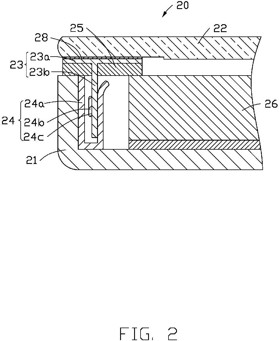
FIG. 2 is a cross-sectional view of a liquid crystal display device having a first embodiment of a first fastener and a second fastener. -
FIG. 3 is a schematic diagram of an embodiment of distribution of the first fastener on a liquid crystal panel. -
FIG. 4 is a schematic diagram of another embodiment of distribution of the first fastener on the liquid crystal panel. -
FIG. 5 is a schematic diagram of an embodiment of distribution of the second fastener on a backboard. -
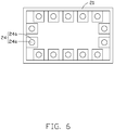
FIG. 6 is a schematic diagram of another embodiment of distribution of the second fastener on the backboard. -
FIG. 7 is a cross-sectional view of the liquid crystal display device having a second embodiment of a first fastener and a second fastener. -
FIG. 8 is a cross-sectional view of the liquid crystal display device having a third embodiment of a first fastener and a second fastener. -
FIG. 9 is a schematic diagram of an embodiment of distribution of the second fastener inFIG. 8 on the backboard. -
FIG. 10 is a schematic diagram of another embodiment of distribution of the second fastener inFIG. 8 on the backboard. -
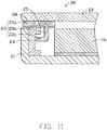
FIG. 11 is a cross-sectional view of the liquid crystal display device having a fourth embodiment of a first fastener and a second fastener. -
FIG. 12 is a cross-sectional view showing assembly of the liquid crystal panel to the backboard. -
FIG. 13 is a cross-section view showing disassembly of the liquid crystal panel from the backboard. - It will be appreciated that for simplicity and clarity of illustration, where appropriate, reference numerals have been repeated among the different figures to indicate corresponding or analogous elements. Additionally, numerous specific details are set forth in order to provide a thorough understanding of the embodiments described herein. However, it will be understood by those of ordinary skill in the art that the embodiments described herein can be practiced without these specific details. In other instances, methods, procedures and components have not been described in detail so as not to obscure the related relevant feature being described. The drawings are not necessarily to scale and the proportions of certain parts may be exaggerated to better illustrate details and features. The description is not to be considered as limiting the scope of the embodiments described herein.
- Several definitions that apply throughout this disclosure will now be presented.
- The term "coupled" is defined as connected, whether directly or indirectly through intervening components, and is not necessarily limited to physical connections. The connection can be such that the objects are permanently connected or releasably connected. The term "substantially" is defined to be essentially conforming to the particular dimension, shape, or other word that "substantially" modifies, such that the component need not be exact. For example, "substantially cylindrical" means that the object resembles a cylinder, but can have one or more deviations from a true cylinder. The term "comprising" means "including, but not necessarily limited to"; it specifically indicates open-ended inclusion or membership in a so-described combination, group, series and the like.
-
FIG. 2 shows an embodiment of a liquidcrystal display device 20 including abackboard 21, aliquid crystal panel 22, afirst fastener 23, and asecond fastener 24. Thebackboard 21 is for mounting a backlight. Theliquid crystal panel 22 is for displaying an image on a light path of the backlight. Thefirst fastener 23 is disposed on a peripheral portion of theliquid crystal panel 22 adjacent to thebackboard 21 and is fixed to theliquid crystal panel 22. Thesecond fastener 24 is fixed to a peripheral portion of thebackboard 21 facing theliquid crystal panel 22. Thefirst fastener 23 and thesecond fastener 24 are latched with each other. - In one embodiment, the
first fastener 23 is bonded to theliquid crystal panel 22 by an adhesive 28, and thesecond fastener 24 is fixed to the backboard 21 by welding, riveting, or mechanical locking. Mechanical locking refers to manual or mechanical locking by mechanical means such as screws. An orthographic projection of thefirst fastener 23 and thesecond fastener 24 on theliquid crystal panel 22 does not exceed or partially exceed an outermost edge of theliquid crystal panel 22. - In one embodiment, the
first fastener 23 and thesecond fastener 24 are engaged with each other by elastic engagement, so that theliquid crystal panel 22 and the backboard 21 are fixed together. Elastic engagement refers to thefirst fastener 23 being partially engaged with thesecond fastener 24 by being partially embedded and engaged with thesecond fastener 24 in a direction perpendicular to theliquid crystal panel 22 toward the backboard 21 and being tightly engaged and fixed by thesecond fastener 24, so that thefirst fastener 23 or thesecond fastener 24 undergoes a certain elastic deformation. -
FIG. 2 shows a first embodiment of thefirst fastener 23 and thesecond fastener 24. Thefirst fastener 23 includes amain portion 23a and at least one protrudingportion 23b extending from themain portion 23a toward thebackboard 21. A surface of themain portion 23a facing away from the protrudingportion 23b is bonded to theliquid crystal panel 22. In one embodiment, the liquidcrystal display device 20 includes onefirst fastener 23. As shown inFIG. 3 , themain portion 23a is annularly distributed around a periphery of theliquid crystal panel 22. Themain portion 23a is spaced apart from a plurality of protrudingportions 23b, and a specific quantity of the protrudingportions 23b can be designed according to actual needs. In one embodiment, referring toFIG. 2 andFIG. 4 , the liquidcrystal display device 20 includes a plurality offirst fasteners 23, each of which includes amain portion 23a and a protrudingportion 23b. The plurality offirst fasteners 23 are spaced around the periphery of theliquid crystal panel 22, and a specific quantity of thefirst fasteners 23 can be designed according to actual needs. - Referring to
FIG. 2 again, thesecond fastener 24 includes abonding portion 24a and at least one latchingportion 24b. Thebonding portion 24a is fixed to at least one of a sidewall or a bottom wall of thebackboard 21. The latchingportion 24b defines achannel 24c for receiving and fixing the protrudingportion 23b of thefirst fastener 23. A shape of thechannel 24c matches a shape of the protrudingportions 23b. For example, if the protrudingportion 23b is cylindrical, thechannel 24c is cylindrical, or if the protrudingportion 23b is rectangular parallelepiped shaped, thechannel 24c is rectangular parallelepiped shaped. An inner diameter of thechannel 24c may be slightly smaller than a width of the protrudingportion 23b so that the protrudingportion 23b can be tightly fit in thechannel 24c after being inserted into thechannel 24c. In other words, the protrudingportion 23b undergoes a slight elastic deformation after being inserted into thechannel 24c, and thefirst fastener 23 and thesecond fastener 24 can be fixed to each other by interference fit between an inner wall of thechannel 24c and the protrudingportion 23b. Thus, a position of theliquid crystal panel 22 relative to the backboard 21 is fixed, and thefirst fastener 23 and thesecond fastener 24 replaces themiddle frame 13 of the related art to reduce or eliminate a width A of themiddle frame 13. - The
liquid crystal panel 22 and thefirst fastener 23 are regarded as a first component, and thesecond fastener 24 and the backboard 21 are regarded as a second component. A quantity of the latchingportions 24b is equal to a quantity of the protrudingportions 23b. When the latchingportions 24b and the corresponding protrudingportions 23b are engaged with each other, the first component and the second component achieve a stable laminated assembly. - In one embodiment, as shown in
FIG. 2 andFIG. 5 , the liquidcrystal display device 20 includes onesecond fastener 24, and thesecond fastener 24 includes onebonding portion 24a and a same quantity of latchingportions 24b as the protrudingportions 23b. The latchingportion 24a is disposed around a periphery of thebackboard 21. In another embodiment, as shown inFIG. 2 andFIG. 6 , the liquidcrystal display device 20 includes a plurality ofsecond fasteners 24, each of which includes abonding portion 24a and a latchingportion 24b. The plurality ofsecond fasteners 24 are spaced around a periphery of the backboard 21 at intervals. - Referring to
FIG. 2 again, a bufferedlight shielding layer 25 is disposed on a surface of a portion of thefirst fastener 23 facing away from theliquid crystal panel 22. The bufferedlight shielding layer 25 functions as a buffer when thefirst fastener 23 and thesecond fastener 24 are fixed together. It can be understood that thefirst fastener 23 and thesecond fastener 24 correspond to a non-display area of the display device including the liquidcrystal display device 20, so that the bufferedlight shielding layer 25 prevents a backlight of the display area from leaking light at an edge of the display device. The bufferedlight shielding layer 25 may be made of rubber. - The liquid
crystal display device 20 further includes an optical film set 26 disposed between the backboard 21 and theliquid crystal panel 22 and spaced apart from thesecond fastener 24. The optical film set 26 evenly distributes and diffuses light emitted from a backlight disposed on the backboard 21 to obtain a uniform backlight that can be used for display. The optical film set 26 can include a reflective film, a diffusion film, and brightness enhancement film such as a prism sheet, a light guide plate, or the like. - The liquid
crystal display device 20 connects theliquid crystal panel 22 and the backboard 21 together by engagement between thefirst fastener 23 and thesecond fastener 24, thereby omitting the middle frame in the related art, so that there is no exposed portion of the middle frame, and a width of the liquidcrystal display device 20 is reduced. -
FIG. 7 shows a second embodiment of thefirst fastener 23 and thesecond fastener 24. In the second embodiment, thefirst fastener 23 and thesecond fastener 24 are engaged by elastic engagement. The liquidcrystal display device 20 of the second embodiment includes at least onefirst fastener 23 and at least onesecond fastener 24. In one embodiment, the liquidcrystal display device 20 includes a plurality offirst fasteners 23 and a plurality ofsecond fasteners 24. The plurality ofsecond fasteners 24 are disposed at intervals around the periphery of thebackboard 21. The plurality offirst fasteners 23 correspond one-to-one with the plurality ofsecond fasteners 24 and are disposed at intervals around the periphery of theliquid crystal panel 22. In one embodiment, theliquid crystal panel 22 includes onefirst fastener 23 including a plurality ofmain portions 23a and a plurality of protrudingportions 23b respectively extending from themain portions 23a toward thebackboard 21. - An end of the protruding
portion 23b of thefirst fastener 23 is substantially spherical. Thesecond fastener 24 includes twoopposite sidewalls 241, and the twosidewalls 241 cooperatively define a receivingcavity 242 and anopening 243. Theopening 243 communicates with the receivingcavity 242. Ends of the twosidewalls 241 adjacent to theopening 243 are bent away from each other to form an inclined portion to facilitate insertion of the spherical end of the protrudingportion 23b. The twosidewalls 241 curve away from each other to form an arced portion to surround the receivingcavity 242 for receiving the spherical end of the protrudingportion 23b. A diameter of a circle formed at a joint between the inclined portion and the arced portion is less than a diameter of the spherical end of the protrudingportion 23b, so that the spherical end of the protrudingportion 23b is not easily removed out of the receivingcavity 242, and thefirst fastener 23 is engaged with thesecond fastener 24. It can be understood that the end of the protrudingportion 23b is inserted into the receivingcavity 242 from theopening 243, and thesecond fastener 24 undergoes a certain elastic deformation, that is, thesidewalls 241 are deformed outward by the spherical end of the protrudingportion 23b to expand theopening 243. In one embodiment, a bottom of thesecond fastener 24 is fixed to thebackboard 21. -
FIGS. 8-9 or8 and10 show a third embodiment of thefirst fastener 23 and thesecond fastener 24 engaged with each other by sliding engagement. The sliding engagement refers to thefirst fastener 23 sliding from an open end of thesecond fastener 24, that is, an open end k shown inFIG. 9 , into an interior of thesecond fastener 24 in a direction parallel to a bottom of thebackboard 21. In this way, thesecond fastener 24 does not elastically deform. - As shown in
FIG. 8 , an end of the protrudingportion 23b of thefirst fastener 23 includes a latching end 23c. When the protrudingportion 23b is inserted into thesecond fastener 24 through the open end k, the latching end 23c is blocked by a portion of thesecond fastener 24 to prevent the latching end 23c from being detached from thesecond fastener 24 in a direction perpendicular to a plane of thebackboard 21. Thus, thefirst fastener 23 and thesecond fastener 24 can be fixed together. In one embodiment, a side of thesecond fastener 24 facing away from the backboard 21 defines agap 245 communicating with the receivingspace 244 through which thefirst fastener 23 is inserted. A width of thegap 245 is less than a maximum width of the latching end 23c, so that the latching end 23c is prevented from being removed out of the receivingspace 244 in a direction perpendicular to the plane of thebackboard 21. - Referring to
FIG. 9 , when theliquid crystal panel 22 and thefirst fastener 23 are moved in a direction parallel to the backboard 21 along a direction I from a side m of the backboard 21 to a side n of the backboard 21, the protrudingportion 23b of thefirst fastener 23 is inserted into thesecond fastener 24 through the open end k. At least one extendingportion 27 is disposed on the side m of the backboard 21 to prevent theliquid crystal panel 22 from moving opposite the direction I and thereby prevent the protrudingportion 23b from sliding out of the open end k of thesecond fastener 24. In one embodiment, a plurality ofsecond fasteners 24 are disposed on the backboard 21 around the periphery of the backboard 21, and a specific quantity of thesecond fasteners 24 can be designed according to actual needs. - Referring to
FIG. 8 and10 , the liquidcrystal display device 20 includes twosecond fasteners 24 respectively disposed in two corners of the backboard 21 adjacent to the side n. A length of eachsecond fastener 24 is not more than half a length of a short side of thebackboard 21. It can be understood that thefirst fasteners 23 are disposed on theliquid crystal panel 22 corresponding to the distribution of thesecond fasteners 24, and a quantity of the latching ends 23c is equal to a quantity of thesecond fasteners 24. A length of the protrudingportion 23b of thefirst fastener 23 is not more than half of the length of the short side of thebackboard 21. -
FIG. 11 shows a fourth embodiment of thefirst fastener 23 and thesecond fastener 24 engaged with each other by a sliding engagement. Thesecond fastener 24 has a concave shape and defines a recess for receiving the latching end 23c of thefirst fastener 23. A side of thesecond fastener 24 facing away from the recess is fixed to a sidewall of thebackboard 21. The latching end 23c and the protrudingportion 23b of thefastener 23 are coupled substantially perpendicularly together. The latching end 23c is inserted into the recess by sliding engagement between thefirst fastener 23 and thesecond fastener 24, and the latching end 23c is received between the optical film set 26 and thesecond fastener 24. Thus, thefirst fastener 23 and thesecond fastener 24 are fixed together in a direction perpendicular to the plane of the backboard 21 to fix a relative position of theliquid crystal panel 22 and thebackboard 21. - A method of assembling the liquid
crystal display device 20 includes fixing thefirst fastener 23 to theliquid crystal panel 22, fixing thesecond fastener 24 to the backboard 21 by welding, riveting or mechanically locking, and then engaging thefirst fastener 23 with thesecond fastener 24 to fix the relative positions of thefirst fastener 23 and thesecond fastener 24. -
FIGS. 12-13 show an embodiment of a process of engaging thefirst fastener 23 with thesecond fastener 24 and removing thefirst fastener 23 from thesecond fastener 24 in the second embodiment of thefirst fastener 23 and thesecond fastener 24. A surface of theliquid crystal panel 22 facing away from thefirst fastener 23 is uniformly pressed by apressing device 30, so that thefirst fastener 23 is partially inserted into thesecond fastener 24 to be engaged and fixed. - As shown in
FIG. 12 , thepressing device 30 includes a pressing plate 31 and a plurality ofsuction cups 32 spaced apart from each other on the pressing plate 31. When the pressing plate 31 is evenly pressed, the plurality ofsuction cups 32 evenly press theliquid crystal panel 22 to cause the protrudingportion 23b of thefirst fastener 23 to insert into thesecond fastener 24. - As shown in
FIG. 13 , to remove thefirst fastener 23 from thesecond fastener 24, thesuction cups 30 pull theliquid crystal panel 22 away from the backboard 21, so that thefirst fastener 23 is removed from thesecond fastener 24. The suction cups 32 adhere to the surface of theliquid crystal panel 22 so that thesuction cups 32 do not detach from theliquid crystal panel 22 when theliquid crystal panel 22 is pulled away from thebackboard 21. - The embodiments shown and described above are only examples. Even though numerous characteristics and advantages of the present technology have been set forth in the foregoing description, together with details of the structure and function of the present disclosure, the disclosure is illustrative only, and changes may be made in the detail, including in matters of shape, size and arrangement of the parts within the principles of the present disclosure up to, and including, the full extent established by the broad general meaning of the terms used in the claims.
Claims (14)
- A liquid crystal display device (20) comprising:a backboard (21) mounting a backlight; anda liquid crystal panel (22) displaying images on a light path of the backlight;wherein:the liquid crystal panel (22) comprises a first fastener (23) and a second fastener (24);the first fastener (23) is disposed and fixed on a peripheral portion of a side of the liquid crystal panel (22) facing the backboard (21);the second fastener (24) is fixed to a peripheral portion of the backboard (21) facing the liquid crystal panel (22); andthe first fastener (23) and the second fastener (24) are engaged with each other.
- The liquid crystal display device (20) of claim 1, wherein:
the first fastener (23) is adhered to the liquid crystal panel (22) by an adhesive (28). - The liquid crystal display device (20) of claim 1, wherein:
the second fastener (24) is fixed to the backboard (21) by welding, riveting, or mechanical locking. - The liquid crystal display device (20) of claim 1, wherein:
the first fastener (23) and the second fastener (24) are engaged with each other by sliding engagement. - The liquid crystal display device (20) of claim 4, wherein:the first fastener (23) comprises a latching end (23c);the latching end (23c) is slid along a direction parallel to a plane of the backboard (21) to insert the latching end (23c) through an open end (k) of the second fastener (24) into the second fastener (24) to engage the first fastener (23) with the second fastener (24).
- The liquid crystal display of claim 1, wherein;
the first fastener (23) is engaged with the second fastener (24) by elastic engagement. - The liquid crystal display of claim 6, wherein:the first fastener (23) comprises a protruding portion (23b);the second fastener (24) comprises a latching portion (24b) defining a channel (24c) for receiving the protruding portion (23b) by interference fit.
- The liquid crystal display of claim 6, wherein:the first fastener (23) comprises a protruding portion (23b);an end of the protruding portion (23b) forms a spherical end;the second fastener (24) comprises two sidewalls (241) cooperatively defining a receiving cavity (242) and an opening (243), the opening (243) communicating with the receiving cavity (242);ends of the two sidewalls (241) adjacent to the opening (243) are bent away from each other to form an inclined portion;the two sidewalls (241) curve away from each other to form an arced portion surrounding the receiving cavity (242);a diameter of a circle formed at a joint between the inclined portion and the arced portion is less than a diameter of the spherical end of the protruding portion (23b);the spherical end is inserted into the receiving cavity (242) from the opening (243), and the opening (243) is elastically expanded as the spherical end is inserted through the opening (243) to engage the first fastener (23) with the second fastener (24).
- The liquid crystal display device (20) of claim 1, wherein:
the first fastener (23) comprises a buffered light shielding layer (25) disposed on a surface of a portion of the first fastener (23) facing away from the liquid crystal panel (22). - The liquid crystal display device (20) of claim 1, wherein:
an orthographic projection of the first fastener (23) and the second fastener (24) on the liquid crystal panel (22) does not exceed or partially exceed an outermost edge of the liquid crystal panel (22). - A method of assembling a liquid crystal display device (20), the method comprising:fixing a first fastener (23) to a liquid crystal panel (22);fixing a second fastener (24) to a backboard (21);engaging the first fastener (23) with the second fastener (24) to fix the first fastener (23) and the second fastener (24) together.
- The method of claim 11, wherein:
the first fastener (23) and the second fastener (24) are engaged together by sliding engagement. - The method of claim 11, wherein;
the first fastener (23) and the second fastener (24) are engaged together by elastic engagement. - The method of claim 13, wherein;
a surface of the liquid crystal panel (22) is evenly pressed by a pressing device to cause the first fastener (23) to partially insert into the second fastener (24) to engage the first fastener (23) with the second fastener (24).
Applications Claiming Priority (1)
| Application Number | Priority Date | Filing Date | Title |
|---|---|---|---|
| CN201910394498.7A CN111929934A (en) | 2019-05-13 | 2019-05-13 | Liquid crystal display module and manufacturing method thereof |
Publications (1)
| Publication Number | Publication Date |
|---|---|
| EP3739378A1 true EP3739378A1 (en) | 2020-11-18 |
Family
ID=70058180
Family Applications (1)
| Application Number | Title | Priority Date | Filing Date |
|---|---|---|---|
| EP20166640.1A Withdrawn EP3739378A1 (en) | 2019-05-13 | 2020-03-30 | Liquid crystal display device and method for assembling same |
Country Status (5)
| Country | Link |
|---|---|
| US (1) | US10845634B1 (en) |
| EP (1) | EP3739378A1 (en) |
| JP (1) | JP2020187359A (en) |
| CN (1) | CN111929934A (en) |
| TW (1) | TWI727328B (en) |
Families Citing this family (4)
| Publication number | Priority date | Publication date | Assignee | Title |
|---|---|---|---|---|
| KR102593462B1 (en) * | 2019-09-02 | 2023-10-24 | 엘지디스플레이 주식회사 | Display Device |
| CN113376887B (en) * | 2021-06-30 | 2023-03-14 | 北京小米移动软件有限公司 | Display module and display device |
| TWI800284B (en) * | 2021-12-22 | 2023-04-21 | 瑞儀光電股份有限公司 | Assembly structure, backlight module and display device |
| CN118742948A (en) * | 2022-12-05 | 2024-10-01 | 广州视源电子科技股份有限公司 | Screen frame component, display device and interactive tablet |
Citations (3)
| Publication number | Priority date | Publication date | Assignee | Title |
|---|---|---|---|---|
| WO2014056196A1 (en) * | 2012-10-08 | 2014-04-17 | 深圳市华星光电技术有限公司 | Backlight module and liquid crystal display apparatus |
| US20150362787A1 (en) * | 2014-06-11 | 2015-12-17 | Boe Technology Group Co., Ltd. | Display module |
| US20170261804A1 (en) * | 2014-01-28 | 2017-09-14 | Boe Technology Group Co., Ltd. | Bezel-free display device |
Family Cites Families (19)
| Publication number | Priority date | Publication date | Assignee | Title |
|---|---|---|---|---|
| TW520153U (en) * | 2002-06-25 | 2003-02-01 | Jin-Fa Chen | Embedding structure of heat sink suitable for automatic processing |
| JP5344249B2 (en) * | 2009-02-10 | 2013-11-20 | Nltテクノロジー株式会社 | Liquid crystal display |
| US20100208161A1 (en) * | 2009-02-19 | 2010-08-19 | Victor Company Of Japan, Limited | Backlight device and liquid crystal display |
| US20140226081A1 (en) * | 2011-09-08 | 2014-08-14 | Sharp Kabushiki Kaisha | Display unit and television receiving apparatus |
| KR101937912B1 (en) * | 2011-10-10 | 2019-01-14 | 엘지디스플레이 주식회사 | Liquid crystal display device module |
| US9274359B2 (en) * | 2012-06-20 | 2016-03-01 | Apple Inc. | Electronic device display chassis |
| CN102809835B (en) * | 2012-08-21 | 2015-06-03 | 深圳市华星光电技术有限公司 | Borderless LCD device |
| US9122099B2 (en) | 2012-10-08 | 2015-09-01 | Shenzhen China Star Optoelectronics Technology Co., Ltd. | Backlight module and liquid crystal display device |
| CN103792696A (en) * | 2012-10-31 | 2014-05-14 | 鑫成科技(成都)有限公司 | Display device |
| KR20150027969A (en) * | 2013-09-05 | 2015-03-13 | 삼성디스플레이 주식회사 | Liquid Crystal Display device united Touch Screen Panel |
| US9690128B2 (en) * | 2014-07-25 | 2017-06-27 | Lg Display Co., Ltd. | Liquid crystal display apparatus |
| JP6597617B2 (en) * | 2014-08-05 | 2019-10-30 | ソニー株式会社 | Display device |
| CN105988235A (en) * | 2015-02-27 | 2016-10-05 | 苏州璨宇光学有限公司 | Display module |
| CN205014163U (en) * | 2015-08-28 | 2016-02-03 | 瑞仪光电(苏州)有限公司 | Backlight module and have this backlight module's display device |
| KR101786884B1 (en) * | 2015-11-30 | 2017-10-18 | 엘지디스플레이 주식회사 | Different form of display device having hole |
| KR101702589B1 (en) * | 2015-11-30 | 2017-02-03 | 엘지디스플레이 주식회사 | Different form of display device having hole |
| US20190154908A1 (en) * | 2016-05-11 | 2019-05-23 | Sharp Kabushiki Kaisha | Lighting device and display device |
| CN106444123A (en) * | 2016-09-22 | 2017-02-22 | 青岛海信电器股份有限公司 | Liquid crystal module and liquid crystal display device |
| KR102275123B1 (en) * | 2017-06-15 | 2021-07-09 | 엘지디스플레이 주식회사 | Liquid crystal display device |
-
2019
- 2019-05-13 CN CN201910394498.7A patent/CN111929934A/en active Pending
- 2019-05-29 TW TW108118644A patent/TWI727328B/en not_active IP Right Cessation
- 2019-06-18 US US16/444,204 patent/US10845634B1/en not_active Expired - Fee Related
-
2020
- 2020-03-30 EP EP20166640.1A patent/EP3739378A1/en not_active Withdrawn
- 2020-05-13 JP JP2020084755A patent/JP2020187359A/en active Pending
Patent Citations (3)
| Publication number | Priority date | Publication date | Assignee | Title |
|---|---|---|---|---|
| WO2014056196A1 (en) * | 2012-10-08 | 2014-04-17 | 深圳市华星光电技术有限公司 | Backlight module and liquid crystal display apparatus |
| US20170261804A1 (en) * | 2014-01-28 | 2017-09-14 | Boe Technology Group Co., Ltd. | Bezel-free display device |
| US20150362787A1 (en) * | 2014-06-11 | 2015-12-17 | Boe Technology Group Co., Ltd. | Display module |
Also Published As
| Publication number | Publication date |
|---|---|
| JP2020187359A (en) | 2020-11-19 |
| US10845634B1 (en) | 2020-11-24 |
| CN111929934A (en) | 2020-11-13 |
| US20200363675A1 (en) | 2020-11-19 |
| TWI727328B (en) | 2021-05-11 |
| TW202041940A (en) | 2020-11-16 |
Similar Documents
| Publication | Publication Date | Title |
|---|---|---|
| US10845634B1 (en) | Liquid crystal display device and method for assembling same | |
| US9470920B2 (en) | Mold frame for curved displaying and curved liquid crystal display device using same | |
| KR100959685B1 (en) | Backlight retention assembly | |
| US10557985B2 (en) | Backlight assembly and display apparatus | |
| CN105842919A (en) | Backlight unit, display module and display equipment | |
| EP2075626A1 (en) | Liquid crystal display panel | |
| WO2018090733A1 (en) | Frame structure of interactive intelligent panel, and interactive intelligent panel | |
| US9791740B2 (en) | Backlight module and liquid crystal display | |
| US20180217314A1 (en) | Backlight module, method for assembling the same and display device | |
| WO2014032343A1 (en) | Liquid crystal display module and liquid crystal display device | |
| TWM537230U (en) | Backlight module and display device | |
| US20170168228A1 (en) | Backlight module and display device | |
| US7766535B2 (en) | Panel guide member and display device having the same | |
| US10495910B1 (en) | Display device | |
| WO2014056196A1 (en) | Backlight module and liquid crystal display apparatus | |
| US20250211664A1 (en) | Backlight module and display device | |
| US20070076139A1 (en) | Liquid crystal display device | |
| CN205581472U (en) | Backlight unit , display module assembly and display device | |
| US11300818B2 (en) | Frame assembly for a slim display device, and application of the frame assembly to a backlight module and display device | |
| CN112068352A (en) | Backlight module and LCD module | |
| CN215867455U (en) | Backlight plate, backlight module and display device | |
| US9122099B2 (en) | Backlight module and liquid crystal display device | |
| CN218788249U (en) | Display components and monitors | |
| US10389967B1 (en) | Removable attachment structure and display device | |
| CN215642171U (en) | Display device |
Legal Events
| Date | Code | Title | Description |
|---|---|---|---|
| PUAI | Public reference made under article 153(3) epc to a published international application that has entered the european phase |
Free format text: ORIGINAL CODE: 0009012 |
|
| STAA | Information on the status of an ep patent application or granted ep patent |
Free format text: STATUS: REQUEST FOR EXAMINATION WAS MADE |
|
| 17P | Request for examination filed |
Effective date: 20200330 |
|
| AK | Designated contracting states |
Kind code of ref document: A1 Designated state(s): AL AT BE BG CH CY CZ DE DK EE ES FI FR GB GR HR HU IE IS IT LI LT LU LV MC MK MT NL NO PL PT RO RS SE SI SK SM TR |
|
| AX | Request for extension of the european patent |
Extension state: BA ME |
|
| STAA | Information on the status of an ep patent application or granted ep patent |
Free format text: STATUS: THE APPLICATION IS DEEMED TO BE WITHDRAWN |
|
| 18D | Application deemed to be withdrawn |
Effective date: 20210519 |