EP3739221A1 - Verin hydraulique equipe d'un dispositif de ralentissement de fin de course - Google Patents
Verin hydraulique equipe d'un dispositif de ralentissement de fin de course Download PDFInfo
- Publication number
- EP3739221A1 EP3739221A1 EP20174231.9A EP20174231A EP3739221A1 EP 3739221 A1 EP3739221 A1 EP 3739221A1 EP 20174231 A EP20174231 A EP 20174231A EP 3739221 A1 EP3739221 A1 EP 3739221A1
- Authority
- EP
- European Patent Office
- Prior art keywords
- hydraulic
- piston
- cylinder
- finger
- seat
- Prior art date
- Legal status (The legal status is an assumption and is not a legal conclusion. Google has not performed a legal analysis and makes no representation as to the accuracy of the status listed.)
- Granted
Links
Images

Classifications
-
- B—PERFORMING OPERATIONS; TRANSPORTING
- B64—AIRCRAFT; AVIATION; COSMONAUTICS
- B64C—AEROPLANES; HELICOPTERS
- B64C25/00—Alighting gear
- B64C25/02—Undercarriages
-
- F—MECHANICAL ENGINEERING; LIGHTING; HEATING; WEAPONS; BLASTING
- F15—FLUID-PRESSURE ACTUATORS; HYDRAULICS OR PNEUMATICS IN GENERAL
- F15B—SYSTEMS ACTING BY MEANS OF FLUIDS IN GENERAL; FLUID-PRESSURE ACTUATORS, e.g. SERVOMOTORS; DETAILS OF FLUID-PRESSURE SYSTEMS, NOT OTHERWISE PROVIDED FOR
- F15B15/00—Fluid-actuated devices for displacing a member from one position to another; Gearing associated therewith
- F15B15/20—Other details, e.g. assembly with regulating devices
- F15B15/22—Other details, e.g. assembly with regulating devices for accelerating or decelerating the stroke
- F15B15/223—Other details, e.g. assembly with regulating devices for accelerating or decelerating the stroke having a piston with a piston extension or piston recess which completely seals the main fluid outlet as the piston approaches its end position
-
- F—MECHANICAL ENGINEERING; LIGHTING; HEATING; WEAPONS; BLASTING
- F15—FLUID-PRESSURE ACTUATORS; HYDRAULICS OR PNEUMATICS IN GENERAL
- F15B—SYSTEMS ACTING BY MEANS OF FLUIDS IN GENERAL; FLUID-PRESSURE ACTUATORS, e.g. SERVOMOTORS; DETAILS OF FLUID-PRESSURE SYSTEMS, NOT OTHERWISE PROVIDED FOR
- F15B15/00—Fluid-actuated devices for displacing a member from one position to another; Gearing associated therewith
- F15B15/20—Other details, e.g. assembly with regulating devices
- F15B15/22—Other details, e.g. assembly with regulating devices for accelerating or decelerating the stroke
- F15B15/227—Other details, e.g. assembly with regulating devices for accelerating or decelerating the stroke having an auxiliary cushioning piston within the main piston or the cylinder end face
-
- B—PERFORMING OPERATIONS; TRANSPORTING
- B64—AIRCRAFT; AVIATION; COSMONAUTICS
- B64C—AEROPLANES; HELICOPTERS
- B64C25/00—Alighting gear
- B64C25/02—Undercarriages
- B64C25/08—Undercarriages non-fixed, e.g. jettisonable
- B64C25/10—Undercarriages non-fixed, e.g. jettisonable retractable, foldable, or the like
- B64C25/18—Operating mechanisms
- B64C25/22—Operating mechanisms fluid
-
- F—MECHANICAL ENGINEERING; LIGHTING; HEATING; WEAPONS; BLASTING
- F01—MACHINES OR ENGINES IN GENERAL; ENGINE PLANTS IN GENERAL; STEAM ENGINES
- F01B—MACHINES OR ENGINES, IN GENERAL OR OF POSITIVE-DISPLACEMENT TYPE, e.g. STEAM ENGINES
- F01B11/00—Reciprocating-piston machines or engines without rotary main shaft, e.g. of free-piston type
- F01B11/02—Equalising or cushioning devices
-
- F—MECHANICAL ENGINEERING; LIGHTING; HEATING; WEAPONS; BLASTING
- F15—FLUID-PRESSURE ACTUATORS; HYDRAULICS OR PNEUMATICS IN GENERAL
- F15B—SYSTEMS ACTING BY MEANS OF FLUIDS IN GENERAL; FLUID-PRESSURE ACTUATORS, e.g. SERVOMOTORS; DETAILS OF FLUID-PRESSURE SYSTEMS, NOT OTHERWISE PROVIDED FOR
- F15B15/00—Fluid-actuated devices for displacing a member from one position to another; Gearing associated therewith
- F15B15/20—Other details, e.g. assembly with regulating devices
- F15B15/22—Other details, e.g. assembly with regulating devices for accelerating or decelerating the stroke
Definitions
- Hydraulic jacks are known, used in particular for maneuvering aircraft landing gears, comprising a cylinder in which a piston is mounted to slide.
- the piston delimits in the cylinder a hydraulic extension chamber and a hydraulic retraction chamber connected to a hydraulic circuit by respective ports.
- This type of jack can be equipped with an end-of-travel slowing device to slow down the movement of the rod during a retraction of the rod as it approaches the stop.
- the port associated with the extension chamber opens out at the bottom of a cavity in the end of the cylinder.
- the rod has a protrusion which, on approaching the end stop, fits snugly into the cavity, forcing the fluid still contained in the extension chamber to flow through the annular space left between the protrusion and the wall of the cavity, which generates an increase in pressure in the extension chamber which brakes the piston and contributes to slowing down the rod before it reaches the stop.
- This slowing down device requires high machining precision and very calibrated operating clearances. It is also sensitive to temperature variations since the annular flow is essentially laminar while it is turbulent at high temperatures, which causes a large variation in the damping coefficient.
- the object of the invention is to provide a telescopic hydraulic cylinder equipped with means for slowing the rod at the end of the stroke which are simple to implement and which are not very sensitive to temperature.
- a hydraulic jack comprising a cylinder in which a piston integral with a rod is mounted to slide tightly to delimit in the cylinder a hydraulic extension chamber and a hydraulic retraction chamber connected to respective ports, the hydraulic cylinder comprising means for slowing down the piston when the piston approaches a retracted position.
- the slowing means comprise first and second hydraulic conduits extending from the extension port to the extension chamber, the first hydraulic conduit comprising a seat while the piston carries a retractable finger having one end which comes to bear against the seat to close the first when the piston approaches the retracted position, so that only the second hydraulic duct remains open while the piston finishes its stroke towards the retracted position.
- the first hydraulic duct is closed, and the fluid is forced to flow through the second duct, which decreases the flow section of the fluid and therefore exerts a resistance which slows down the flow.
- piston finishing its stroke towards the retracted position. The finger then retracts progressively in the piston as the latter moves, while remaining resting against the seat.
- the hydraulic conduits extend in a bottom of the cylinder.
- the seat is attached to the bottom of the cylinder.
- the hydraulic conduits are made in an attached diaphragm or in a calibrated hole in the bottom of the cylinder.
- the finger is slidably mounted on the piston along a central axis of the cylinder.
- the end of the finger is conical to allow better guidance.
- the finger is retractable against the action of return means pushing the finger towards a protruding position of the piston.
- a drain is also provided in the body to avoid trapping the pressure between the rod and the body of the retractable finger.
- the seat is preceded by a ferrule intended to cooperate with the end of the finger before the latter comes to bear against the seat to progressively reduce a passage section of the first duct. hydraulic and allow centering (conical or circular).
- the extension port P is connected to the extension chamber 5 by a first hydraulic pipe 7 of sufficiently large diameter to induce only minor pressure drops, and a second hydraulic pipe 8 of larger diameter. weak, intentionally forming a restriction for the passage of fluid.
- the piston 2 carries a finger 10 slidably mounted on the piston 2, here along the longitudinal axis X, against the action of a spring 11 which returns the finger to a protruding position defined by the cooperation of a collar 16 projecting from an end portion of the finger 10 with a shoulder of a cavity 17 of the piston 2 receiving the spring 11 and said end portion of the finger 10.
- the first hydraulic duct 7 comprises a seat 13 attached to the second base 3 and arranged opposite a conical end 14 of the finger 10.
- the finger 10, the spring 11, the seat 13, and the two hydraulic conduits 7, 8 together form the slowing device of the invention, the operation of which is now detailed.
- the second hydraulic conduit 8 comprises a localized restriction of section so that the flow of fluid through the second hydraulic conduit 8 generates an increase in pressure in the extension chamber 5 which contributes to slowing down the piston 2. It will be noted that such a flow occurs in a turbulent regime.
- the orifice forming the localized restriction of section which is here drilled in a thin plate mounted transversely in the hydraulic pipe 8 (said plate being symbolized only on the figure 1 ), will make it possible to increase the speed of the fluid and will generate turbulence, so that the resistance it generates is not very sensitive to the temperature of the fluid. It is essential that the plate in which the orifice is made have as thin a thickness as possible in order to obtain a flow qualified as “thin-walled”.
- the piston 2 then continues its stroke at reduced speed to the retracted position illustrated in figure 3 , the fluid then flowing only through the second hydraulic conduit 8.
- the spring 11 ensures the support of the end 14 of the finger 10 against the seat 13 so that the first hydraulic conduit 7 remains closed, while allowing retraction. finger 10 in the piston 2.
- the calibration of the restriction organized by the second hydraulic conduit 8 can be obtained by drilling to a calibrated diameter of this second conduit, or by using a suitable restrictor.
- the fluid contained in the cavity 17 should be easily discharged during the retraction of the finger 10, in order to avoid an increase in the pressure of the fluid in the cavity 17 which could cause a damping phenomenon resistant to the retraction of the finger. finger 10.
- the stiffness of the spring 11 should be calibrated to ensure good support for the end 14 of the finger 10 on the seat 13, without generating a contact shock which would prematurely wear the seat 13.
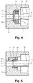
- the first hydraulic duct 7 and the second hydraulic duct 8 are made in a diaphragm 18 fitted in the second bottom 3 of the cylinder 1.
- the seat 13 is then simply made up of the edge delimiting the edge of the first hydraulic duct 7 facing the end 14 of the finger 10.
- the precision machining production of the hydraulic conduits 7 and 8) can be carried out on a separate part, in a suitable material (for example bronze).
- a separate seat can be mounted on the diaphragm 18, similarly to the cylinder of the figures 1 to 3 .
- the seat 13 is preceded by a ferrule 15, which may as illustrated here be integral with the seat 13, and which has the function of cooperating with the end 14 of the finger 10 to progressively reduce a passage section of the fluid through the first hydraulic conduit 7 before the end 14 comes to bear against the seat 13 and closes the conduit, in order to reduce or eliminate the pressure surges during the closing of the first hydraulic conduit 7.
- the ferrule 15 has a conical internal shape, but any other shape suitable for gradually closing the first hydraulic conduit 7 can be used.
- the conical internal shape of the shell 15 thus has a circular passage section which decreases in going towards the seat according to a progressive slope.
- the progressive slope allows a limitation of the speed of the piston, creating a progressive damping, and therefore the rise in pressure in the main extension chamber when the sliding piston arrives on the seat contained in the bearing.
- the fluid flow thus decreases more progressively than without a slope.
- the internal shape of the ferrule is dimensioned to also provide guidance of the finger. Indeed, the dimensional tolerances of several parts must be taken into account to ensure that the finger reaches the seat. Such a shape makes it possible to reduce the machining uncertainties and the precision classes required for machining the parts.
- the slope and the seat will preferably be made in the same room to allow better control of the sliding, the guiding and especially the sealing.
- the fluid is forced to pass through the diaphragm, the hydraulic diameter of which is small, causing turbulent flow, as in a thin-walled orifice.
- the finger is here arranged on the piston to slide and retract along the longitudinal axis X
- the finger can be placed so that it slides along any other axis parallel to the longitudinal axis X.
- the finger 10 here has a conical end 14, this end can be given any shape capable of cooperating with the facing seat to close the first hydraulic duct 7.
- the section restriction can be machined into or attached to the cylinder body or diaphragm.
- the jack of the invention is particularly advantageous for use in an aircraft landing gear, in particular for maneuvering this landing gear between the extended position and the retracted position of the landing gear.
- the jack of the invention can also be used as an actuator to move a movable element relative to a fixed element of an aircraft, for example a movable flight surface, a shroud of a thrust reverser ... Nevertheless, of other applications of the jack of the invention can be envisaged, for example as an actuator on ships or land motor vehicles.
Landscapes
- Engineering & Computer Science (AREA)
- Mechanical Engineering (AREA)
- General Engineering & Computer Science (AREA)
- Physics & Mathematics (AREA)
- Fluid Mechanics (AREA)
- Aviation & Aerospace Engineering (AREA)
- Actuator (AREA)
Abstract
Description
- On connaît des vérins hydrauliques, utilisés notamment pour la manœuvre des trains d'atterrissage des aéronefs, comportant un cylindre dans lequel un piston est monté pour coulisser. Le piston délimite dans le cylindre une chambre hydraulique d'extension et une chambre hydraulique de rétraction reliées à un circuit hydraulique par des ports respectifs. Ce type de vérin peut être équipé d'un dispositif de ralentissement de fin de course pour ralentir le déplacement de la tige lors d'une rétraction de la tige à l'approche de la butée. A cet effet, le port associé à la chambre d'extension débouche au fond d'une cavité aménagée dans l'extrémité du cylindre. La tige comporte une protrusion qui, à l'approche de la butée de fin de course, pénètre à ajustement dans la cavité, obligeant le fluide encore contenu dans la chambre d'extension à s'écouler par l'espace annulaire laissé entre la protrusion et la paroi de la cavité, ce qui génère une augmentation de pression dans la chambre d'extension qui freine le piston et contribue à ralentir la tige avant son arrivée en butée.
- Ce dispositif de ralentissement demande une grande précision d'usinage et des jeux de fonctionnement très calibrés. Il est en outre sensible aux variations de températures puisque l'écoulement annulaire est essentiellement laminaire alors qu'il est turbulent aux températures élevées, ce qui occasionne une variation importante du coefficient d'amortissement.
- L'invention a pour objet de proposer un vérin hydraulique télescopique équipé de moyens de ralentissement de la tige en fin de course simples à implémenter et peu sensibles à la température.
- En vue de la réalisation de cette fonction, on propose un vérin hydraulique comportant un cylindre dans lequel un piston solidaire d'une tige est monté à coulissement étanche pour délimiter dans le cylindre une chambre hydraulique d'extension et une chambre hydraulique de rétraction reliées à des ports respectifs, le vérin hydraulique comportant des moyens de ralentissement du piston quand le piston s'approche d'une position rétractée. Selon l'invention, les moyens de ralentissement comportent des premier et deuxième conduits hydrauliques s'étendant du port d'extension à la chambre d'extension, le premier conduit hydraulique comportant un siège tandis que le piston porte un doigt rétractable ayant une extrémité qui vient en appui contre le siège pour fermer le premier quand le piston s'approche de la position rétractée, de sorte que seul le deuxième conduit hydraulique reste ouvert alors que le piston finit sa course vers la position rétractée.
- Ainsi, lorsque le doigt vient en appui contre le siège, le premier conduit hydraulique est fermé, et le fluide est contraint de s'écouler par le deuxième conduit, ce qui diminue la section de passage du fluide et exerce donc une résistance qui ralentit le piston finissant sa course vers la position rétractée. Le doigt se rétracte alors progressivement dans le piston au fur et à mesure du déplacement de celui-ci, tout en restant en appui contre le siège.
- Cette disposition est très simple à mettre en œuvre et ne nécessite pas l'exécution de jeux de fonctionnement précis. Il suffit de permettre au doigt de flotter transversalement pour permettre son autocentrage dans le siège et garantir une fermeture sinon étanche, du moins suffisamment importante pour en pratique forcer le fluide à passer par le deuxième conduit.
- Selon une disposition particulière de l'invention, les conduits hydrauliques s'étendent dans un fond du cylindre. De préférence alors, le siège est rapporté sur le fond du cylindre.
- Alternativement, les conduits hydrauliques sont réalisés dans un diaphragme rapporté ou dans un trou calibré dans le fond du cylindre.
- De préférence, le doigt est monté coulissant sur le piston selon un axe central du cylindre.
- Selon une autre disposition particulière de l'invention, l'extrémité du doigt est conique pour permettre un meilleur guidage.
- Le doigt est rétractable à l'encontre de l'action de moyens de rappel poussant le doigt vers une position saillante du piston. Un drain est aussi prévu dans le corps pour éviter d'emprisonner la pression entre la tige et le corps du doigt rétractable.
- Selon encore une autre disposition particulière de l'invention, le siège est précédé d'une virole destinée à coopérer avec l'extrémité du doigt avant que celle-ci ne vienne en appui contre le siège pour diminuer progressivement une section de passage du premier conduit hydraulique et permettre le centrage (conique ou circulaire).
- L'invention sera mieux comprise à la lumière de la description qui suit des figures des dessins annexés, parmi lesquelles :
- [
Fig. 1 ] Lafigure 1 est une vue en coupe schématique d'un vérin hydraulique muni d'un dispositif de ralentissement selon l'invention, illustré alors que le piston approche de la position rétractée, l'extrémité du doigt n'étant pas encore en appui contre le siège ; - [
Fig.2 ] Lafigure 2 est une vue analogue à celle de lafigure 1 , le même vérin étant illustré au moment où l'extrémité du doigt vient au contact du siège ; - [
Fig.3 ] Lafigure 3 est une vue analogue à celle de lafigure 1 , le même vérin étant illustré au moment où le piston arrive en position rétractée ; - [
Fig.4 ] Lafigure 4 illustre une variante de réalisation du vérin de lafigure 1 , dans laquelle le deuxième fond reçoit un diaphragme dans lequel sont réalisés les deux conduits hydrauliques ; - [
Fig.5 ] Lafigure 5 montre un siège pouvant équiper le vérin de lafigure 1 ou de lafigure 4 , le siège étant associé à une virole d'entrée qui coopère avec l'extrémité du doigt pour fermer progressivement une section de passage du premier conduit. - En référence aux
figures 1 à 3 , l'invention s'applique à un vérin hydraulique 100 comportant un cylindre 1 creux dans lequel un piston 2 est monté pour coulisser selon un axe longitudinal X, ici l'axe central du cylindre 1. Le cylindre est délimité de part et d'autre par un premier fond (non visible ici) traversé par une tige 4 solidaire du piston 2, et un deuxième fond 3 visible ici. Le piston 2 délimite dans le cylindre 1 une chambre hydraulique d'extension 5 et une chambre hydraulique de rétraction 6. La chambre d'extension est ici reliée à un port d'expansion P. - Selon l'invention, le port d'extension P est relié à la chambre d'extension 5 par un premier conduit hydraulique 7 de diamètre suffisamment important pour n'induire que des pertes de charges mineures, et un deuxième conduit hydraulique 8 de diamètre plus faible, formant volontairement une restriction pour le passage du fluide.
- En outre, le piston 2 porte un doigt 10 monté coulissant sur le piston 2, ici selon l'axe longitudinal X, à l'encontre de l'action d'un ressort 11 qui rappelle le doigt vers une position saillante définie par la coopération d'une collerette 16 s'étendant en saillie d'une portion d'extrémité du doigt 10 avec un épaulement d'une cavité 17 du piston 2 recevant le ressort 11 et ladite portion d'extrémité du doigt 10. Le premier conduit hydraulique 7 comporte un siège 13 rapporté sur le deuxième fond 3 et disposé en regard d'une extrémité conique 14 du doigt 10. Le doigt 10, le ressort 11, le siège 13, et les deux conduits hydrauliques 7, 8 forment ensemble le dispositif de ralentissement de l'invention, dont le fonctionnement est maintenant détaillé.
- Lorsque du fluide sous pression est admis dans la chambre de rétraction 6, le piston 2 se déplace en direction du deuxième fond 3. Tant que le piston 2 est éloigné du deuxième fond 3, comme illustré à la
figure 1 , l'extrémité 14 du doigt 10 est éloignée du siège 13 et le fluide présent dans la chambre d'extension 5 est expulsé de celle-ci vers le port P via le premier conduit hydraulique 7. - Le piston 2 continuant sa course, l'extrémité 14 du doigt 10 vient en appui contre le siège 13, comme illustré à la
figure 2 , ce qui ferme le premier conduit hydraulique 7 et oblige le fluide à s'écouler via le deuxième conduit hydraulique 8. Le deuxième conduit hydraulique 8 comprend une restriction localisée de section de sorte que l'écoulement du fluide par le deuxième conduit hydraulique 8 génère une augmentation de pression dans la chambre d'extension 5 qui contribue à ralentir le piston 2. On notera qu'un tel écoulement se produit en régime turbulent. L'orifice formant la restriction localisée de section, qui est ici percé dans une plaque mince montée transversalement dans le conduit hydraulique 8 (ladite plaque n'étant symbolisée que sur lafigure 1 ), va permettre d'augmenter la vitesse du fluide et va générer la turbulence, de sorte que la résistance qu'il génère est peu sensible à la température du fluide. Il est indispensable que la plaque dans laquelle l'orifice est ménagé ait une épaisseur aussi fine que possible afin d'obtenir un écoulement qualifié de « à mince paroi ». - Le piston 2 continue alors sa course à vitesse réduite jusqu'à la position rétractée illustrée à la
figure 3 , le fluide s'écoulant alors uniquement par le deuxième conduit hydraulique 8. Le ressort 11 garantit l'appui de l'extrémité 14 du doigt 10 contre le siège 13 de sorte que le premier conduit hydraulique 7 reste fermé, tout en permettant la rétraction du doigt 10 dans le piston 2. - Pour garantir la bonne fermeture du premier conduit hydraulique 7, il suffit de prévoir un guidage axial du doigt 10 dans le piston 2 suffisamment flottant pour permettre un autocentrage de l'extrémité 14 du doigt 10 dans le siège 13. En pratique, on prévoira une extrémité 14 suffisamment longue pour faciliter cet autocentrage. Le calibrage de la restriction organisée par le deuxième conduit hydraulique 8 peut être obtenu par un perçage à un diamètre calibré de ce deuxième conduit, ou par l'utilisation d'un restricteur adéquat. Il convient de permettre une évacuation facile du fluide contenu dans la cavité 17 lors de la rétraction du doigt 10, afin d'éviter un accroissement de la pression du fluide dans la cavité 17 qui pourrait provoquer un phénomène d'amortissement résistant à la rétraction du doigt 10. De même, il convient de calibrer la raideur du ressort 11 pour assurer un bon appui de l'extrémité 14 du doigt 10 sur le siège 13, sans pour autant générer un choc au contact qui userait prématurément le siège 13.
- Lorsqu'il est nécessaire de faire sortir la tige 4, on admet du fluide sous pression par le port d'extension P. Le fluide repousse le doigt 10 contre l'action du ressort 11 de sorte que le fluide peut accéder à la chambre d'extension par le premier conduit hydraulique 7.
- Selon une variante de réalisation illustrée à la
figure 4 , le premier conduit hydraulique 7 et le deuxième conduit hydraulique 8 sont réalisés dans un diaphragme 18 rapporté dans le deuxième fond 3 du cylindre 1. Le siège 13 est alors constitué simplement de l'arête délimitant le bord du premier conduit hydraulique 7 en regard de l'extrémité 14 du doigt 10. Ainsi, les usinages de précision (réalisation des conduits hydrauliques 7 et 8) peuvent être réalisés sur une pièce séparée, dans un matériau adapté (par exemple du bronze). Bien entendu, un siège séparé peut être monté sur le diaphragme 18, de façon similaire au vérin desfigures 1 à 3 . - Selon une autre variante de réalisation illustrée à la
figure 5 , on fait précéder le siège 13 d'une virole 15, qui peut comme illustré ici être venue de matière avec le siège 13, et qui a pour fonction de coopérer avec l'extrémité 14 du doigt 10 pour diminuer progressivement une section de passage du fluide par le premier conduit hydraulique 7 avant que l'extrémité 14 ne vienne en appui contre le siège 13 et ferme le conduit, afin de diminuer ou supprimer les à-coups de pression lors de la fermeture du premier conduit hydraulique 7. Ici, la virole 15 a une forme interne conique, mais toute autre forme adaptée à fermer progressivement le premier conduit hydraulique 7 est utilisable. La forme interne conique de la virole 15 a ainsi une section de passage circulaire qui diminue en allant vers le siège selon une pente progressive. - La pente progressive autorise une limitation de la vitesse du piston, en créant un amortissement progressif, et donc la montée en pression dans la chambre principale d'extension lorsque le piston coulissant arrive sur le siège contenu dans le palier. L'écoulement du fluide diminue ainsi de façon plus progressive qu'en l'absence de pente.
- Avantageusement, la forme interne de la virole est dimensionnée pour réaliser aussi un guidage du doigt. Effectivement, les tolérances dimensionnelles de plusieurs pièces sont à prendre en compte pour assurer que le doigt arrive sur le siège. Une telle forme permet de diminuer les incertitudes d'usinage et les classes de précision demandées pour l'usinage des pièces. La pente et le siège seront de préférence réalisés dans la même pièce pour permettre une meilleure maitrise du coulissement, du guidage et surtout de l'étanchéité.
- Une fois le doigt en appui sur le siège, le fluide est obligé de passer par le diaphragme dont le diamètre hydraulique est petit provoquant un écoulement turbulent, comme dans un orifice à mince paroi.
- L'invention n'est pas limitée à ce qui vient d'être décrit, mais englobe au contraire toute variante entrant dans le cadre défini par les revendications.
- En particulier, bien que le doigt soit ici disposé sur le piston pour coulisser et se rétracter selon l'axe longitudinal X, on pourra disposer le doigt pour qu'il coulisse selon tout autre axe parallèle à l'axe longitudinal X.
- Bien qu'ici le doigt 10 ait une extrémité conique 14, on pourra donner à cette extrémité toute forme apte à coopérer avec le siège en regard pour fermer le premier conduit hydraulique 7.
- La restriction de section peut être usinée dans le corps du cylindre ou le diaphragme, ou être rapportée sur ceux-ci.
- Le vérin de l'invention est particulièrement intéressant pour une utilisation dans un train d'atterrissage d'aéronef, en particulier pour la manœuvre de ce train d'atterrissage entre la position sortie et la position rentrée du train d'atterrissage. Le vérin de l'invention est également utilisable comme actionneur pour mouvoir un élément mobile par rapport à un élément fixe d'un aéronef, par exemple une surface mobile de vol, un carénage d'un inverseur de poussée... Néanmoins, d'autres applications du vérin de l'invention sont envisageables, par exemple en tant qu'actionneur sur des navires ou des véhicules automobiles terrestres.
Claims (12)
- Vérin hydraulique comportant un cylindre (1) dans lequel un piston (2) solidaire d'une tige (4) est monté à coulissement étanche pour délimiter dans le cylindre une chambre hydraulique d'extension (5) et une chambre hydraulique de rétraction (6) reliées à des ports respectifs, le vérin hydraulique comportant des moyens de ralentissement du piston quand le piston s'approche d'une position rétractée, caractérisé en ce que les moyens de ralentissement comportent des premier et deuxième conduits hydrauliques (7, 8) s'étendant entre le port d'extension et la chambre d'extension, le premier conduit hydraulique comportant un siège (13) tandis que le piston porte un doigt (10) rétractable ayant une extrémité (14) qui vient en appui contre le siège pour fermer le premier conduit hydraulique (7) quand le piston s'approche de la position rétractée, de sorte que seul le deuxième conduit hydraulique (8) reste ouvert alors que le piston finit sa course vers la position rétractée.
- Vérin hydraulique selon la revendication 1, dans lequel le siège (13) est précédé d'une virole (15) destiné à coopérer avec l'extrémité (14) du doigt (10) avant que celle-ci ne vienne en appui contre le siège pour diminuer progressivement une section de passage du premier conduit hydraulique (7).
- Vérin hydraulique selon la revendication 2, dans lequel le siège (13) et la virole (15) sont d'une seule pièce.
- Vérin hydraulique selon la revendication 2 ou la revendication 3, dans lequel la virole a une forme interne dimensionnée pour réaliser aussi un guidage du doigt.
- Vérin hydraulique selon l'une quelconque des revendications précédentes, dans lequel les conduits hydrauliques (7, 8) s'étendent dans un fond (3) du cylindre (1) .
- Vérin hydraulique selon la revendication 5, dans lequel le siège (13) est rapporté sur le fond du cylindre (1) .
- Vérin hydraulique selon l'une quelconque des revendications 1 à 4, dans lequel les conduits hydrauliques (7,8) sont réalisés dans un diaphragme (18) rapporté dans le cylindre (1).
- Vérin hydraulique selon l'une des revendications précédentes, dans lequel le doigt (10) est monté coulissant sur le piston selon un axe central (X) du cylindre.
- Vérin hydraulique selon l'une des revendications précédentes, dans lequel l'extrémité (14) du doigt (10) est conique.
- Vérin hydraulique selon l'une des revendications précédentes, dans lequel le doigt (10) est rétractable à l'encontre de l'action de moyens de rappel (11) poussant le doigt vers une position saillante du piston.
- Train d'atterrissage comportant un vérin de manœuvre du train d'atterrissage entre une position rentrée et une position sortie, caractérisé en ce que le vérin est conforme à l'une quelconque des revendications précédentes.
- Aéronef comportant un train d'atterrissage conforme à la revendication 11.
Applications Claiming Priority (1)
| Application Number | Priority Date | Filing Date | Title |
|---|---|---|---|
| FR1904966A FR3096097B1 (fr) | 2019-05-13 | 2019-05-13 | Vérin hydraulique equipé d’un dispositif de ralentissement de fin de course |
Publications (2)
| Publication Number | Publication Date |
|---|---|
| EP3739221A1 true EP3739221A1 (fr) | 2020-11-18 |
| EP3739221B1 EP3739221B1 (fr) | 2023-09-13 |
Family
ID=67441470
Family Applications (1)
| Application Number | Title | Priority Date | Filing Date |
|---|---|---|---|
| EP20174231.9A Active EP3739221B1 (fr) | 2019-05-13 | 2020-05-12 | Verin hydraulique equipe d'un dispositif de ralentissement de fin de course |
Country Status (3)
| Country | Link |
|---|---|
| US (1) | US11268549B2 (fr) |
| EP (1) | EP3739221B1 (fr) |
| FR (1) | FR3096097B1 (fr) |
Families Citing this family (3)
| Publication number | Priority date | Publication date | Assignee | Title |
|---|---|---|---|---|
| WO2020237344A1 (fr) * | 2019-05-31 | 2020-12-03 | Hydra Dyne Technology Inc. | Amortissement de course dans des dispositifs à piston et cylindre |
| US11319972B1 (en) * | 2021-05-11 | 2022-05-03 | Caterpillar Inc. | Hydraulic cylinder snubbing retention arrangement |
| BR112023019007A2 (pt) * | 2021-03-23 | 2023-10-10 | Caterpillar Inc | Disposição de retenção de amortecimento de cilindro hidráulico |
Citations (4)
| Publication number | Priority date | Publication date | Assignee | Title |
|---|---|---|---|---|
| FR633581A (fr) * | 1926-06-16 | 1928-01-31 | Nat Pneumatic Co | Moteur à fluide sous pression |
| US2553810A (en) * | 1948-12-09 | 1951-05-22 | George W Houlsby Jr | Fluid control device |
| US4138928A (en) * | 1977-02-11 | 1979-02-13 | Ware Machine Service Inc. | Fluid actuated apparatus |
| EP3150863A1 (fr) * | 2015-09-30 | 2017-04-05 | Sumitomo Precision Products Co., Ltd. | Cylindre hydraulique pour train d'atterrissage d'avion |
Family Cites Families (5)
| Publication number | Priority date | Publication date | Assignee | Title |
|---|---|---|---|---|
| US3067726A (en) * | 1961-02-27 | 1962-12-11 | Int Basic Economy Corp | Cushioning structure for fluid power cylinders |
| US3999463A (en) * | 1975-02-27 | 1976-12-28 | Componetrol, Inc. | Fluid motor construction |
| GB1536417A (en) * | 1975-06-19 | 1978-12-20 | Emhart Ind | Cylinder and piston assemblies |
| GB9421002D0 (en) * | 1994-10-18 | 1994-12-07 | Norgren Martonair Gmbh | Fluid powered cylinder |
| US10202988B2 (en) * | 2016-06-17 | 2019-02-12 | Deere & Company | Cushion mechanism for a hydraulic cylinder |
-
2019
- 2019-05-13 FR FR1904966A patent/FR3096097B1/fr active Active
-
2020
- 2020-05-12 EP EP20174231.9A patent/EP3739221B1/fr active Active
- 2020-05-12 US US16/872,857 patent/US11268549B2/en active Active
Patent Citations (4)
| Publication number | Priority date | Publication date | Assignee | Title |
|---|---|---|---|---|
| FR633581A (fr) * | 1926-06-16 | 1928-01-31 | Nat Pneumatic Co | Moteur à fluide sous pression |
| US2553810A (en) * | 1948-12-09 | 1951-05-22 | George W Houlsby Jr | Fluid control device |
| US4138928A (en) * | 1977-02-11 | 1979-02-13 | Ware Machine Service Inc. | Fluid actuated apparatus |
| EP3150863A1 (fr) * | 2015-09-30 | 2017-04-05 | Sumitomo Precision Products Co., Ltd. | Cylindre hydraulique pour train d'atterrissage d'avion |
Also Published As
| Publication number | Publication date |
|---|---|
| FR3096097A1 (fr) | 2020-11-20 |
| US11268549B2 (en) | 2022-03-08 |
| EP3739221B1 (fr) | 2023-09-13 |
| FR3096097B1 (fr) | 2021-09-24 |
| US20200362887A1 (en) | 2020-11-19 |
Similar Documents
| Publication | Publication Date | Title |
|---|---|---|
| EP3739221B1 (fr) | Verin hydraulique equipe d'un dispositif de ralentissement de fin de course | |
| EP2048408B1 (fr) | Amortisseur d'un véhicule | |
| EP2964946B1 (fr) | Tuyere a section de col variable de propulseur d'engin aerospatial munie d'un pointeau mobile | |
| FR2984832A1 (fr) | Soupape de chambre accumulatrice a commande hydraulique | |
| CA2610063C (fr) | Organe telescopique a butee interne effacable | |
| EP0066795B1 (fr) | Vanne d'arrêt à fermeture rapide pour fluide compressible | |
| FR2939174A1 (fr) | Amortisseur pneumatique | |
| EP2891825A2 (fr) | Actionneur téléscopique | |
| EP3685080B1 (fr) | Vanne thermostatique pour véhicule automobile | |
| EP3724740B1 (fr) | Vanne thermostatique | |
| EP1364890A1 (fr) | Dispositif de décharge brusque d'air | |
| FR2738885A1 (fr) | Verin a pression fluide d'une chambre intermediaire coulissante | |
| EP2964973A1 (fr) | Vérin auto-bloquant pour ouvrant de véhicule automobile | |
| EP3524860B1 (fr) | Organe de pilotage | |
| FR3056517A1 (fr) | Dispositif de nettoyage, destine a projeter au moins un fluide vers une surface a nettoyer d'un vehicule automobile, tel qu'une surface optique d'un capteur d'un systeme de detection optique | |
| EP3477415B1 (fr) | Vanne thermostatique | |
| EP1102938B1 (fr) | Piston et dispositif de commande hydraulique d'un embrayage de vehicule automobile comportant un tel piston | |
| FR2876757A1 (fr) | Verin, de preference double effet, a amortisseur de fin de course | |
| FR2836705A1 (fr) | Verin comprenant une admission de fluide unique pour les largages d'une charge | |
| FR2993623A1 (fr) | Dispositif amortisseur hydraulique | |
| FR3001017A1 (fr) | Amortisseur a coefficient d'amortissement variable et train d'atterrissage d'aeronef comportant un tel amortisseur | |
| FR2463306A1 (fr) | Verin telescopique | |
| FR2650041A1 (fr) | Amortisseur oleopneumatique de fin de course | |
| FR3080651A1 (fr) | Inverseur de poussee avec systeme d’ouverture et de fermeture optimise | |
| FR2870440A1 (fr) | Etui tournant a deplacement du curseur hydraulique pour rouge a levres ou similaire |
Legal Events
| Date | Code | Title | Description |
|---|---|---|---|
| PUAI | Public reference made under article 153(3) epc to a published international application that has entered the european phase |
Free format text: ORIGINAL CODE: 0009012 |
|
| STAA | Information on the status of an ep patent application or granted ep patent |
Free format text: STATUS: THE APPLICATION HAS BEEN PUBLISHED |
|
| AK | Designated contracting states |
Kind code of ref document: A1 Designated state(s): AL AT BE BG CH CY CZ DE DK EE ES FI FR GB GR HR HU IE IS IT LI LT LU LV MC MK MT NL NO PL PT RO RS SE SI SK SM TR |
|
| AX | Request for extension of the european patent |
Extension state: BA ME |
|
| STAA | Information on the status of an ep patent application or granted ep patent |
Free format text: STATUS: REQUEST FOR EXAMINATION WAS MADE |
|
| 17P | Request for examination filed |
Effective date: 20210421 |
|
| RBV | Designated contracting states (corrected) |
Designated state(s): AL AT BE BG CH CY CZ DE DK EE ES FI FR GB GR HR HU IE IS IT LI LT LU LV MC MK MT NL NO PL PT RO RS SE SI SK SM TR |
|
| STAA | Information on the status of an ep patent application or granted ep patent |
Free format text: STATUS: EXAMINATION IS IN PROGRESS |
|
| 17Q | First examination report despatched |
Effective date: 20220217 |
|
| GRAP | Despatch of communication of intention to grant a patent |
Free format text: ORIGINAL CODE: EPIDOSNIGR1 |
|
| STAA | Information on the status of an ep patent application or granted ep patent |
Free format text: STATUS: GRANT OF PATENT IS INTENDED |
|
| INTG | Intention to grant announced |
Effective date: 20230412 |
|
| GRAS | Grant fee paid |
Free format text: ORIGINAL CODE: EPIDOSNIGR3 |
|
| GRAA | (expected) grant |
Free format text: ORIGINAL CODE: 0009210 |
|
| STAA | Information on the status of an ep patent application or granted ep patent |
Free format text: STATUS: THE PATENT HAS BEEN GRANTED |
|
| AK | Designated contracting states |
Kind code of ref document: B1 Designated state(s): AL AT BE BG CH CY CZ DE DK EE ES FI FR GB GR HR HU IE IS IT LI LT LU LV MC MK MT NL NO PL PT RO RS SE SI SK SM TR |
|
| REG | Reference to a national code |
Ref country code: CH Ref legal event code: EP |
|
| REG | Reference to a national code |
Ref country code: DE Ref legal event code: R096 Ref document number: 602020017507 Country of ref document: DE |
|
| REG | Reference to a national code |
Ref country code: IE Ref legal event code: FG4D Free format text: LANGUAGE OF EP DOCUMENT: FRENCH |
|
| REG | Reference to a national code |
Ref country code: LT Ref legal event code: MG9D |
|
| REG | Reference to a national code |
Ref country code: NL Ref legal event code: MP Effective date: 20230913 |
|
| PG25 | Lapsed in a contracting state [announced via postgrant information from national office to epo] |
Ref country code: GR Free format text: LAPSE BECAUSE OF FAILURE TO SUBMIT A TRANSLATION OF THE DESCRIPTION OR TO PAY THE FEE WITHIN THE PRESCRIBED TIME-LIMIT Effective date: 20231214 |
|
| PG25 | Lapsed in a contracting state [announced via postgrant information from national office to epo] |
Ref country code: SE Free format text: LAPSE BECAUSE OF FAILURE TO SUBMIT A TRANSLATION OF THE DESCRIPTION OR TO PAY THE FEE WITHIN THE PRESCRIBED TIME-LIMIT Effective date: 20230913 Ref country code: RS Free format text: LAPSE BECAUSE OF FAILURE TO SUBMIT A TRANSLATION OF THE DESCRIPTION OR TO PAY THE FEE WITHIN THE PRESCRIBED TIME-LIMIT Effective date: 20230913 Ref country code: NO Free format text: LAPSE BECAUSE OF FAILURE TO SUBMIT A TRANSLATION OF THE DESCRIPTION OR TO PAY THE FEE WITHIN THE PRESCRIBED TIME-LIMIT Effective date: 20231213 Ref country code: LV Free format text: LAPSE BECAUSE OF FAILURE TO SUBMIT A TRANSLATION OF THE DESCRIPTION OR TO PAY THE FEE WITHIN THE PRESCRIBED TIME-LIMIT Effective date: 20230913 Ref country code: LT Free format text: LAPSE BECAUSE OF FAILURE TO SUBMIT A TRANSLATION OF THE DESCRIPTION OR TO PAY THE FEE WITHIN THE PRESCRIBED TIME-LIMIT Effective date: 20230913 Ref country code: HR Free format text: LAPSE BECAUSE OF FAILURE TO SUBMIT A TRANSLATION OF THE DESCRIPTION OR TO PAY THE FEE WITHIN THE PRESCRIBED TIME-LIMIT Effective date: 20230913 Ref country code: GR Free format text: LAPSE BECAUSE OF FAILURE TO SUBMIT A TRANSLATION OF THE DESCRIPTION OR TO PAY THE FEE WITHIN THE PRESCRIBED TIME-LIMIT Effective date: 20231214 Ref country code: FI Free format text: LAPSE BECAUSE OF FAILURE TO SUBMIT A TRANSLATION OF THE DESCRIPTION OR TO PAY THE FEE WITHIN THE PRESCRIBED TIME-LIMIT Effective date: 20230913 |
|
| REG | Reference to a national code |
Ref country code: AT Ref legal event code: MK05 Ref document number: 1611563 Country of ref document: AT Kind code of ref document: T Effective date: 20230913 |
|
| PG25 | Lapsed in a contracting state [announced via postgrant information from national office to epo] |
Ref country code: NL Free format text: LAPSE BECAUSE OF FAILURE TO SUBMIT A TRANSLATION OF THE DESCRIPTION OR TO PAY THE FEE WITHIN THE PRESCRIBED TIME-LIMIT Effective date: 20230913 |
|
| PG25 | Lapsed in a contracting state [announced via postgrant information from national office to epo] |
Ref country code: IS Free format text: LAPSE BECAUSE OF FAILURE TO SUBMIT A TRANSLATION OF THE DESCRIPTION OR TO PAY THE FEE WITHIN THE PRESCRIBED TIME-LIMIT Effective date: 20240113 |
|
| PG25 | Lapsed in a contracting state [announced via postgrant information from national office to epo] |
Ref country code: AT Free format text: LAPSE BECAUSE OF FAILURE TO SUBMIT A TRANSLATION OF THE DESCRIPTION OR TO PAY THE FEE WITHIN THE PRESCRIBED TIME-LIMIT Effective date: 20230913 |
|
| PG25 | Lapsed in a contracting state [announced via postgrant information from national office to epo] |
Ref country code: ES Free format text: LAPSE BECAUSE OF FAILURE TO SUBMIT A TRANSLATION OF THE DESCRIPTION OR TO PAY THE FEE WITHIN THE PRESCRIBED TIME-LIMIT Effective date: 20230913 |
|
| PG25 | Lapsed in a contracting state [announced via postgrant information from national office to epo] |
Ref country code: SM Free format text: LAPSE BECAUSE OF FAILURE TO SUBMIT A TRANSLATION OF THE DESCRIPTION OR TO PAY THE FEE WITHIN THE PRESCRIBED TIME-LIMIT Effective date: 20230913 Ref country code: RO Free format text: LAPSE BECAUSE OF FAILURE TO SUBMIT A TRANSLATION OF THE DESCRIPTION OR TO PAY THE FEE WITHIN THE PRESCRIBED TIME-LIMIT Effective date: 20230913 Ref country code: IS Free format text: LAPSE BECAUSE OF FAILURE TO SUBMIT A TRANSLATION OF THE DESCRIPTION OR TO PAY THE FEE WITHIN THE PRESCRIBED TIME-LIMIT Effective date: 20240113 Ref country code: ES Free format text: LAPSE BECAUSE OF FAILURE TO SUBMIT A TRANSLATION OF THE DESCRIPTION OR TO PAY THE FEE WITHIN THE PRESCRIBED TIME-LIMIT Effective date: 20230913 Ref country code: EE Free format text: LAPSE BECAUSE OF FAILURE TO SUBMIT A TRANSLATION OF THE DESCRIPTION OR TO PAY THE FEE WITHIN THE PRESCRIBED TIME-LIMIT Effective date: 20230913 Ref country code: CZ Free format text: LAPSE BECAUSE OF FAILURE TO SUBMIT A TRANSLATION OF THE DESCRIPTION OR TO PAY THE FEE WITHIN THE PRESCRIBED TIME-LIMIT Effective date: 20230913 Ref country code: AT Free format text: LAPSE BECAUSE OF FAILURE TO SUBMIT A TRANSLATION OF THE DESCRIPTION OR TO PAY THE FEE WITHIN THE PRESCRIBED TIME-LIMIT Effective date: 20230913 Ref country code: PT Free format text: LAPSE BECAUSE OF FAILURE TO SUBMIT A TRANSLATION OF THE DESCRIPTION OR TO PAY THE FEE WITHIN THE PRESCRIBED TIME-LIMIT Effective date: 20240115 Ref country code: SK Free format text: LAPSE BECAUSE OF FAILURE TO SUBMIT A TRANSLATION OF THE DESCRIPTION OR TO PAY THE FEE WITHIN THE PRESCRIBED TIME-LIMIT Effective date: 20230913 |
|
| PG25 | Lapsed in a contracting state [announced via postgrant information from national office to epo] |
Ref country code: PL Free format text: LAPSE BECAUSE OF FAILURE TO SUBMIT A TRANSLATION OF THE DESCRIPTION OR TO PAY THE FEE WITHIN THE PRESCRIBED TIME-LIMIT Effective date: 20230913 Ref country code: IT Free format text: LAPSE BECAUSE OF FAILURE TO SUBMIT A TRANSLATION OF THE DESCRIPTION OR TO PAY THE FEE WITHIN THE PRESCRIBED TIME-LIMIT Effective date: 20230913 |
|
| REG | Reference to a national code |
Ref country code: DE Ref legal event code: R097 Ref document number: 602020017507 Country of ref document: DE |
|
| PG25 | Lapsed in a contracting state [announced via postgrant information from national office to epo] |
Ref country code: DK Free format text: LAPSE BECAUSE OF FAILURE TO SUBMIT A TRANSLATION OF THE DESCRIPTION OR TO PAY THE FEE WITHIN THE PRESCRIBED TIME-LIMIT Effective date: 20230913 |
|
| PLBE | No opposition filed within time limit |
Free format text: ORIGINAL CODE: 0009261 |
|
| STAA | Information on the status of an ep patent application or granted ep patent |
Free format text: STATUS: NO OPPOSITION FILED WITHIN TIME LIMIT |
|
| PG25 | Lapsed in a contracting state [announced via postgrant information from national office to epo] |
Ref country code: DK Free format text: LAPSE BECAUSE OF FAILURE TO SUBMIT A TRANSLATION OF THE DESCRIPTION OR TO PAY THE FEE WITHIN THE PRESCRIBED TIME-LIMIT Effective date: 20230913 |
|
| 26N | No opposition filed |
Effective date: 20240614 |
|
| PG25 | Lapsed in a contracting state [announced via postgrant information from national office to epo] |
Ref country code: SI Free format text: LAPSE BECAUSE OF FAILURE TO SUBMIT A TRANSLATION OF THE DESCRIPTION OR TO PAY THE FEE WITHIN THE PRESCRIBED TIME-LIMIT Effective date: 20230913 |
|
| PG25 | Lapsed in a contracting state [announced via postgrant information from national office to epo] |
Ref country code: SI Free format text: LAPSE BECAUSE OF FAILURE TO SUBMIT A TRANSLATION OF THE DESCRIPTION OR TO PAY THE FEE WITHIN THE PRESCRIBED TIME-LIMIT Effective date: 20230913 |
|
| PG25 | Lapsed in a contracting state [announced via postgrant information from national office to epo] |
Ref country code: BG Free format text: LAPSE BECAUSE OF FAILURE TO SUBMIT A TRANSLATION OF THE DESCRIPTION OR TO PAY THE FEE WITHIN THE PRESCRIBED TIME-LIMIT Effective date: 20230913 |
|
| PG25 | Lapsed in a contracting state [announced via postgrant information from national office to epo] |
Ref country code: BG Free format text: LAPSE BECAUSE OF FAILURE TO SUBMIT A TRANSLATION OF THE DESCRIPTION OR TO PAY THE FEE WITHIN THE PRESCRIBED TIME-LIMIT Effective date: 20230913 |
|
| REG | Reference to a national code |
Ref country code: CH Ref legal event code: PL |
|
| PG25 | Lapsed in a contracting state [announced via postgrant information from national office to epo] |
Ref country code: MC Free format text: LAPSE BECAUSE OF FAILURE TO SUBMIT A TRANSLATION OF THE DESCRIPTION OR TO PAY THE FEE WITHIN THE PRESCRIBED TIME-LIMIT Effective date: 20230913 |
|
| PG25 | Lapsed in a contracting state [announced via postgrant information from national office to epo] |
Ref country code: LU Free format text: LAPSE BECAUSE OF NON-PAYMENT OF DUE FEES Effective date: 20240512 |
|
| PG25 | Lapsed in a contracting state [announced via postgrant information from national office to epo] |
Ref country code: MC Free format text: LAPSE BECAUSE OF FAILURE TO SUBMIT A TRANSLATION OF THE DESCRIPTION OR TO PAY THE FEE WITHIN THE PRESCRIBED TIME-LIMIT Effective date: 20230913 Ref country code: LU Free format text: LAPSE BECAUSE OF NON-PAYMENT OF DUE FEES Effective date: 20240512 Ref country code: CH Free format text: LAPSE BECAUSE OF NON-PAYMENT OF DUE FEES Effective date: 20240531 |
|
| REG | Reference to a national code |
Ref country code: BE Ref legal event code: MM Effective date: 20240531 |
|
| PG25 | Lapsed in a contracting state [announced via postgrant information from national office to epo] |
Ref country code: IE Free format text: LAPSE BECAUSE OF NON-PAYMENT OF DUE FEES Effective date: 20240512 |
|
| PG25 | Lapsed in a contracting state [announced via postgrant information from national office to epo] |
Ref country code: BE Free format text: LAPSE BECAUSE OF NON-PAYMENT OF DUE FEES Effective date: 20240531 |
|
| PGFP | Annual fee paid to national office [announced via postgrant information from national office to epo] |
Ref country code: DE Payment date: 20250519 Year of fee payment: 6 |
|
| PGFP | Annual fee paid to national office [announced via postgrant information from national office to epo] |
Ref country code: GB Payment date: 20250527 Year of fee payment: 6 |
|
| PGFP | Annual fee paid to national office [announced via postgrant information from national office to epo] |
Ref country code: FR Payment date: 20250526 Year of fee payment: 6 |
|
| PG25 | Lapsed in a contracting state [announced via postgrant information from national office to epo] |
Ref country code: CY Free format text: LAPSE BECAUSE OF FAILURE TO SUBMIT A TRANSLATION OF THE DESCRIPTION OR TO PAY THE FEE WITHIN THE PRESCRIBED TIME-LIMIT; INVALID AB INITIO Effective date: 20200512 |
|
| PG25 | Lapsed in a contracting state [announced via postgrant information from national office to epo] |
Ref country code: HU Free format text: LAPSE BECAUSE OF FAILURE TO SUBMIT A TRANSLATION OF THE DESCRIPTION OR TO PAY THE FEE WITHIN THE PRESCRIBED TIME-LIMIT; INVALID AB INITIO Effective date: 20200512 |