EP3739217A1 - Seal assembly for compressor - Google Patents
Seal assembly for compressor Download PDFInfo
- Publication number
- EP3739217A1 EP3739217A1 EP20171512.5A EP20171512A EP3739217A1 EP 3739217 A1 EP3739217 A1 EP 3739217A1 EP 20171512 A EP20171512 A EP 20171512A EP 3739217 A1 EP3739217 A1 EP 3739217A1
- Authority
- EP
- European Patent Office
- Prior art keywords
- seal
- assembly
- compressor
- impeller
- radially stepped
- Prior art date
- Legal status (The legal status is an assumption and is not a legal conclusion. Google has not performed a legal analysis and makes no representation as to the accuracy of the status listed.)
- Granted
Links
Images


Classifications
-
- F—MECHANICAL ENGINEERING; LIGHTING; HEATING; WEAPONS; BLASTING
- F04—POSITIVE - DISPLACEMENT MACHINES FOR LIQUIDS; PUMPS FOR LIQUIDS OR ELASTIC FLUIDS
- F04D—NON-POSITIVE-DISPLACEMENT PUMPS
- F04D29/00—Details, component parts, or accessories
- F04D29/08—Sealings
- F04D29/16—Sealings between pressure and suction sides
- F04D29/161—Sealings between pressure and suction sides especially adapted for elastic fluid pumps
- F04D29/162—Sealings between pressure and suction sides especially adapted for elastic fluid pumps of a centrifugal flow wheel
-
- F—MECHANICAL ENGINEERING; LIGHTING; HEATING; WEAPONS; BLASTING
- F04—POSITIVE - DISPLACEMENT MACHINES FOR LIQUIDS; PUMPS FOR LIQUIDS OR ELASTIC FLUIDS
- F04D—NON-POSITIVE-DISPLACEMENT PUMPS
- F04D29/00—Details, component parts, or accessories
- F04D29/08—Sealings
- F04D29/083—Sealings especially adapted for elastic fluid pumps
-
- F—MECHANICAL ENGINEERING; LIGHTING; HEATING; WEAPONS; BLASTING
- F04—POSITIVE - DISPLACEMENT MACHINES FOR LIQUIDS; PUMPS FOR LIQUIDS OR ELASTIC FLUIDS
- F04D—NON-POSITIVE-DISPLACEMENT PUMPS
- F04D17/00—Radial-flow pumps, e.g. centrifugal pumps; Helico-centrifugal pumps
- F04D17/08—Centrifugal pumps
- F04D17/10—Centrifugal pumps for compressing or evacuating
- F04D17/12—Multi-stage pumps
-
- F—MECHANICAL ENGINEERING; LIGHTING; HEATING; WEAPONS; BLASTING
- F04—POSITIVE - DISPLACEMENT MACHINES FOR LIQUIDS; PUMPS FOR LIQUIDS OR ELASTIC FLUIDS
- F04D—NON-POSITIVE-DISPLACEMENT PUMPS
- F04D17/00—Radial-flow pumps, e.g. centrifugal pumps; Helico-centrifugal pumps
- F04D17/08—Centrifugal pumps
- F04D17/10—Centrifugal pumps for compressing or evacuating
- F04D17/12—Multi-stage pumps
- F04D17/122—Multi-stage pumps the individual rotor discs being, one for each stage, on a common shaft and axially spaced, e.g. conventional centrifugal multi- stage compressors
-
- F—MECHANICAL ENGINEERING; LIGHTING; HEATING; WEAPONS; BLASTING
- F04—POSITIVE - DISPLACEMENT MACHINES FOR LIQUIDS; PUMPS FOR LIQUIDS OR ELASTIC FLUIDS
- F04D—NON-POSITIVE-DISPLACEMENT PUMPS
- F04D27/00—Control, e.g. regulation, of pumps, pumping installations or pumping systems specially adapted for elastic fluids
-
- F—MECHANICAL ENGINEERING; LIGHTING; HEATING; WEAPONS; BLASTING
- F04—POSITIVE - DISPLACEMENT MACHINES FOR LIQUIDS; PUMPS FOR LIQUIDS OR ELASTIC FLUIDS
- F04D—NON-POSITIVE-DISPLACEMENT PUMPS
- F04D27/00—Control, e.g. regulation, of pumps, pumping installations or pumping systems specially adapted for elastic fluids
- F04D27/02—Surge control
- F04D27/0246—Surge control by varying geometry within the pumps, e.g. by adjusting vanes
-
- F—MECHANICAL ENGINEERING; LIGHTING; HEATING; WEAPONS; BLASTING
- F04—POSITIVE - DISPLACEMENT MACHINES FOR LIQUIDS; PUMPS FOR LIQUIDS OR ELASTIC FLUIDS
- F04D—NON-POSITIVE-DISPLACEMENT PUMPS
- F04D29/00—Details, component parts, or accessories
- F04D29/05—Shafts or bearings, or assemblies thereof, specially adapted for elastic fluid pumps
- F04D29/056—Bearings
- F04D29/058—Bearings magnetic; electromagnetic
-
- F—MECHANICAL ENGINEERING; LIGHTING; HEATING; WEAPONS; BLASTING
- F05—INDEXING SCHEMES RELATING TO ENGINES OR PUMPS IN VARIOUS SUBCLASSES OF CLASSES F01-F04
- F05B—INDEXING SCHEME RELATING TO WIND, SPRING, WEIGHT, INERTIA OR LIKE MOTORS, TO MACHINES OR ENGINES FOR LIQUIDS COVERED BY SUBCLASSES F03B, F03D AND F03G
- F05B2240/00—Components
- F05B2240/50—Bearings
- F05B2240/51—Bearings magnetic
- F05B2240/515—Bearings magnetic electromagnetic
-
- F—MECHANICAL ENGINEERING; LIGHTING; HEATING; WEAPONS; BLASTING
- F05—INDEXING SCHEMES RELATING TO ENGINES OR PUMPS IN VARIOUS SUBCLASSES OF CLASSES F01-F04
- F05B—INDEXING SCHEME RELATING TO WIND, SPRING, WEIGHT, INERTIA OR LIKE MOTORS, TO MACHINES OR ENGINES FOR LIQUIDS COVERED BY SUBCLASSES F03B, F03D AND F03G
- F05B2240/00—Components
- F05B2240/57—Seals
-
- F—MECHANICAL ENGINEERING; LIGHTING; HEATING; WEAPONS; BLASTING
- F05—INDEXING SCHEMES RELATING TO ENGINES OR PUMPS IN VARIOUS SUBCLASSES OF CLASSES F01-F04
- F05B—INDEXING SCHEME RELATING TO WIND, SPRING, WEIGHT, INERTIA OR LIKE MOTORS, TO MACHINES OR ENGINES FOR LIQUIDS COVERED BY SUBCLASSES F03B, F03D AND F03G
- F05B2260/00—Function
- F05B2260/50—Kinematic linkage, i.e. transmission of position
- F05B2260/507—Kinematic linkage, i.e. transmission of position using servos, independent actuators, etc.
-
- F—MECHANICAL ENGINEERING; LIGHTING; HEATING; WEAPONS; BLASTING
- F16—ENGINEERING ELEMENTS AND UNITS; GENERAL MEASURES FOR PRODUCING AND MAINTAINING EFFECTIVE FUNCTIONING OF MACHINES OR INSTALLATIONS; THERMAL INSULATION IN GENERAL
- F16J—PISTONS; CYLINDERS; SEALINGS
- F16J15/00—Sealings
- F16J15/44—Free-space packings
- F16J15/445—Free-space packings with means for adjusting the clearance
Definitions
- the present invention relates to a seal assembly for a compressor.
- Example embodiments relate to electric motor-driven magnetic bearing compressors.
- An exemplary liquid chiller uses a hermetic centrifugal compressor.
- the exemplary unit comprises a standalone combination of the compressor, the cooler unit, the chiller unit, the expansion device, and various additional components.
- Some compressors include a transmission intervening between the motor rotor and the impeller to drive the impeller at a faster speed than the motor.
- the impeller is directly driven by the rotor (e.g., they are on the same shaft).
- Various bearing systems have been used to support compressor shafts.
- One particular class of compressors uses magnetic bearings (more specifically, electromagnetic bearings).
- a pair of radial magnetic bearings may be used. Each of these may be backed up by a mechanical bearing (a so-called “touchdown” bearing).
- one or more other magnetic bearings may be configured to resist loads that draw the shaft upstream (and, also, opposite loads). Upstream movement tightens the clearance between the impeller and its shroud and, thereby, risks damage. Opposite movement may open clearance and reduce efficiency.
- Magnetic bearings use position sensors for adjusting the associated magnetic fields to maintain radial and axial positioning against the associated radial and axial static loads of a given operating condition and further control synchronous vibrations.
- the present invention provides a seal assembly for a compressor.
- the seal assembly includes at least one impeller.
- At least one seal land is associated with the impeller including a plurality of radially stepped surfaces.
- a seal is associated with each of at least one seal lands.
- the seal includes a plurality of radially stepped projections corresponding to the plurality of radially stepped surfaces on at least one seal land.
- At least one actuator is configured to move at least one seal land relative to the seal.
- the at least one actuator is configured to move the seal between a first axial position and a second different axial position.
- At least one seal land is attached to one of the impeller and a housing assembly.
- the seal may be attached to the other of the impeller and the housing assembly.
- the plurality of radially stepped projections include distal ends with an increasing radially dimension in a first axial direction. Adjacent ones of the plurality of radially stepped projections may be separated by a trough.
- the plurality of radially stepped surfaces include an increasing radial dimension in the first axial direction.
- the first axial direction is an axially aft direction.
- the seal is fixed relative to a housing assembly of the compressor.
- At least one seal land may be fixed relative to the impeller.
- the plurality of radially stepped surfaces include three radially stepped surfaces.
- the plurality of radially stepped projections may include three radially stepped projections.
- the invention provides a compressor assembly that includes a seal assembly as discussed above.
- a shaft is in driving engagement with at least one impeller.
- At least one electromagnetic bearing supports the shaft.
- the at least one electromagnetic bearing includes at least one radial support electromagnetic bearing system and at least one axial thrust electromagnetic bearing system.
- the at least one actuator is configured to move the seal between a first axial position and a second different axial position.
- At least one seal land is attached to one of the at least one impeller.
- a housing assembly and the seal may be attached to the other of the at least one impeller and the housing assembly.
- the plurality of radially stepped projections include distal ends with an increasing radial dimension in a first axial direction.
- the plurality of radially stepped surfaces include an increasing radial dimension in the first axial direction. Adjacent ones of the plurality of radially stepped projections may be separated by a trough.
- At least one impeller includes a first stage impeller and a second stage impeller.
- At least one seal assembly may include a first seal assembly associated with the first stage impeller and a second and third seal assembly associated with the second stage impeller.
- the first seal assembly is located on an axially upstream side of the first stage impeller.
- the second seal assembly is located on an axially upstream side of the second stage impeller.
- the third seal assembly is located on an axially downstream side of the second stage impeller.
- the invention provides a method of operating a compressor.
- the method may be a method for operating a compressor having a seal assembly as described above in relation to the first aspect or the second aspect, and optional features thereof.
- the method includes supporting a shaft in the compressor with at least one electromagnetic bearing.
- a seal clearance is determined based on an operating condition of the compressor.
- the seal clearance is increased based on the operating condition by creating axial movement between a seal land attached to one of an impeller and a housing assembly and a seal attached to the other of the impeller and the housing assembly.
- the seal land includes a plurality of radially stepped surfaces.
- the seal may include a plurality of radially stepped projections.
- the operating condition includes at least one of a start-up or a shut-down condition for the compressor to increase seal clearance.
- At least one electromagnetic bearing includes at least one radial support electromagnetic bearing system and at least one axial thrust electromagnetic bearing system.
- FIG. 1 shows a vapor compression system 20.
- the exemplary vapor compression system 20 is a chiller system.
- the system 20 includes a centrifugal compressor 22 having a suction port (inlet) 24 and a discharge port (outlet) 26.
- the system further includes a first heat exchanger 28 in a normal operating mode being a heat rejection heat exchanger (e.g., a gas cooler or condenser).
- the first heat exchanger 28 is a refrigerant-water heat exchanger formed by tube bundles 30, 32 in a condenser unit 34 where the refrigerant is cooled by an external water flow.
- a float valve 36 controls flow through the condenser outlet from a subcooler chamber surrounding the subcooler bundle 32.
- the system further includes a second heat exchanger 38 (in the normal mode a heat absorption heat exchanger or evaporator).
- the second heat exchanger 38 is a refrigerant-water heat exchanger formed by a tube bundle 40 for chilling a chilled water flow within a chiller unit 42.
- the chiller unit 42 includes a refrigerant distributor 44.
- An expansion device 46 is downstream of the compressor and upstream of the evaporator 38 along the normal mode refrigerant flowpath 48 (the flowpath being partially surrounded by associated piping, etc.).
- a hot gas bypass valve 50 is positioned along a bypass flowpath branch 52 extending between a first location downstream of the outlet 26 and upstream of an isolation valve 54 and a second location upstream of the inlet of the cooler and downstream of the expansion device 46.
- the compressor 22 is contained within an exemplary housing assembly 56.
- the housing assembly 56 contains an electric motor 58 for driving a first stage impeller 60 and a second stage impeller 62.
- the electric motor 58 drives the first and second stage impellers 60, 62 in the first mode to compress fluid (refrigerant) to draw fluid (refrigerant) in through the inlet 24, compress the fluid, and discharge the fluid from the outlet 26.
- the first and second stage impellers 60, 62 are directly driven by the electric motor 58.
- the housing assembly 56 defines a motor compartment 64 containing a stator 66 and a rotor 68 of the electric motor 58.
- the rotor 68 is located partially within the stator 66 and is mounted for rotation about a rotor axis A for driving the first and second stage impellers 60, 62.
- the rotor 68 is supported radially relative to the housing assembly 56 with a radial support electromagnetic bearing system 70 located on each opposing axial side of the electric motor 58.
- the rotor 68 is supported axially relative to the housing assembly 56 with an axial thrust electromagnetic bearing system 72 located on each opposing axial side of the electric motor 58.
- the first and second stage impellers 60 and 62 are mounted to a shaft 76 (e.g., to an end portion 78) to rotate with the rotor 68 as a unit about the rotor axis A.
- a shaft 76 e.g., to an end portion 78
- axial or axially and radial or radially is in relation to the rotor axis A unless stated otherwise.
- the compressor 22 includes a controllable inlet guide vane (IGV) array 82 for controlling an amount of fluid entering the compressor 22.
- An outlet 84 of the first stage impeller 60 is fluidly connected with an inlet 86 of the second stage impeller 62 through a fluid passageway 88.
- the fluid passageway 88 extends radially outward from the outlet 84 of the first stage impeller 60 and turns back radially inward to join the inlet 86 of the second stage impeller 62.
- An outlet 90 of the second stage impeller 62 is fluidly connected to an outlet plenum 92 through a fluid passageway 94.
- first stage impeller 60 is sealed with a first seal assembly 96 and the second impeller stage 62 is sealed with a second seal assembly 98 and a third seal assembly 100.
- the first seal assembly 96 includes a stepped seal land 102 forming a circumferential ring on a radially outer side of the inlet 80 to the first stage impeller 60.
- the seal land 102 includes steps 102A, 102B, 102C each having an increasing radially dimension in a downstream direction relative to fluid flow through the compressor 22.
- the first seal assembly 96 also includes a seal 104 forming a complete ring that includes a corresponding number of seal projections 104A, 104B, 104C to the number of steps 102A, 102B, 102C in the seal land 102.
- the seal projections 104A, 104B, 104C include distal ends with an increasing radial dimension in an axially downstream direction and are separated by troughs. A radially outer side of the seal 104 is sealed relative to a portion of the housing assembly 56 through an O-ring 106.
- the first seal assembly 96 is located in the first position as shown in Figure 3A with the first seal 104 located in an axially downstream position with the projections 104A, 104B, 104C axially aligned with a corresponding one of the steps 102A, 102B, 102C in the seal land 102.
- the configuration of Figure 3A creates a labyrinth seal with the projections 104A, 104B, 104C maintaining a close tolerance with the steps 102A, 102B, 102C.
- At least one actuator 108 moves the seal 104 to an axially forward position such that the projections 104A, 104B, 104C are no longer axially aligned with a corresponding one of the steps 102A, 102B, 102C.
- This configuration reduces leakage of fluid between a forward end of the first stage impeller 60 and the housing assembly 56 to provide an increase in efficiency of the compressor 22 during normal operating conditions.
- the second and third seal assemblies 98, 100 are associated with an upstream and downstream side of the second stage impeller 62, respectively.
- the second seal assembly 98 includes a stepped seal land 110 forming a circumferential ring on a radially outer side of the inlet 86 to the second stage impeller 62.
- the seal land 110 includes steps 110A, 110B, 110C each having an increasing radially dimension in a downstream direction relative to fluid flow through the compressor 22.
- the second seal assembly 98 also includes a seal 112 that includes a corresponding number of seal projections 112A, 112B, 112C to the number of steps 110A, 110B, 110C in the seal land 110.
- the seal projections 112A, 112B, 112C include distal ends with an increasing radial dimension in an axially downstream direction and are separated by troughs. A radially outer side of the seal 112 is sealed relative to a portion of the housing assembly 56 through an O-ring 114.
- the second seal assembly 98 is located in a first position as shown in Figure 4A with the first seal 112 forming a complete ring located in an axially downstream position with the projections 112A, 112B, 112C axially aligned with a corresponding one of the steps 110A, 110B, 110C in the second seal land 110.
- the configuration of Figure 4A creates a labyrinth seal with the projections 112A, 112B, 112C maintaining a close tolerance with the steps 110A, 110B, 110C.
- At least one actuator 116 moves the seal 112 to an axially forward position such that the projections 112A, 112B, 112C are no longer axially aligned with a corresponding one of the steps 110A, 110B, 110C.
- This configuration reduces leakage of fluid between a forward end of the second stage impeller 62 and the housing assembly 56 to provide an increase in efficiency of the compressor 22 during normal operating conditions.
- the third seal assembly 100 includes a stepped seal land 118 forming a circumferential ring on an axially aft side of the outlet 90 to the second stage impeller 62.
- the seal land 118 includes steps 118A, 118B, 118C each having an increasing radially dimension in a downstream direction relative to fluid flow through the compressor 22.
- the third seal assembly 100 also includes a seal 120 that includes a corresponding number of seal projections 120A, 120B, 120C to the number of steps 118A, 118B, 118C in the seal land 118.
- the seal projections 118A, 118B, 118C include distal ends with an increasing radial dimension in an axially downstream direction and are separated by troughs. A radially outer side of the seal 118 is sealed relative to a portion of the housing assembly 56 through an O-ring 122.
- the third seal assembly 100 is located in a first position as shown in Figure 4A with the third seal 120 forming a complete ring located in an axially downstream position with the projections 120A, 120B, 120C axially aligned with a corresponding one of the steps 118A, 118B, 118C in the second seal land 110.
- the configuration of Figure 4A creates a labyrinth seal with the projections 120A, 120B, 120C maintaining a close tolerance with the steps 118A, 118B, 118C.
- At least one actuator 124 moves the seal 120 to an axially forward position such that the projections 120A, 120B, 120C are no longer axially aligned with a corresponding one of the steps 118A, 118B, 118C.
- This configuration reduces leakage of fluid between an aft portion of the second stage impeller 62 and the housing assembly 56 to provide an increase in efficiency of the compressor 22 during normal operating conditions.
- a controller 130 determines an operational state of the compressor 22 as shown in the method of operating the compressor 200 in Figure 5 . (Step 202). The controller 130 will then determine if the operational state of the compressor 22 requires increased clearance in the first, second, and third seal assemblies 96, 98, 100. (Step 204). Operational states that may require additional clearance may include at least one of start-up and shut-down conditions. If the controller 103 determines that the compressor 22 is not in an operation state that requires additional clearance, the controller 130 will continue to monitor for changes in the operational state of the compressor 22.
- the controller 130 determines that the compressor 22 is in an operational state that requires additional clearance, the controller 130 sends a signal to increase clearance between the first, second, and third seals 104, 112, 120 and a respective one of the first, second and third seal lands 102, 110, 118. (Step 206).
- the signal from the controller 130 is sent to the actuators 108, 116, and/or 124 to move the first, second, and/or third seals 104, 112, 120 to create additional clearance with the first, second, and third seal lands 102, 110, 118.
- the signal from the controller 130 is sent to the actuator 126 to move the shaft 76 axially as discussed above without moving the first, second, and third seals 104, 112, 120 relative to the housing assembly 56.
Landscapes
- Engineering & Computer Science (AREA)
- Mechanical Engineering (AREA)
- General Engineering & Computer Science (AREA)
- Physics & Mathematics (AREA)
- Geometry (AREA)
- Electromagnetism (AREA)
- Structures Of Non-Positive Displacement Pumps (AREA)
Abstract
Description
- The present invention relates to a seal assembly for a compressor. Example embodiments relate to electric motor-driven magnetic bearing compressors.
- One particular use of electric motor-driven compressors is liquid chillers. An exemplary liquid chiller uses a hermetic centrifugal compressor. The exemplary unit comprises a standalone combination of the compressor, the cooler unit, the chiller unit, the expansion device, and various additional components.
- Some compressors include a transmission intervening between the motor rotor and the impeller to drive the impeller at a faster speed than the motor. In other compressors, the impeller is directly driven by the rotor (e.g., they are on the same shaft).
- Various bearing systems have been used to support compressor shafts. One particular class of compressors uses magnetic bearings (more specifically, electromagnetic bearings). To provide radial support of a shaft, a pair of radial magnetic bearings may be used. Each of these may be backed up by a mechanical bearing (a so-called "touchdown" bearing). Additionally, one or more other magnetic bearings may be configured to resist loads that draw the shaft upstream (and, also, opposite loads). Upstream movement tightens the clearance between the impeller and its shroud and, thereby, risks damage. Opposite movement may open clearance and reduce efficiency.
- Magnetic bearings use position sensors for adjusting the associated magnetic fields to maintain radial and axial positioning against the associated radial and axial static loads of a given operating condition and further control synchronous vibrations.
- Viewed from a first aspect, the present invention provides a seal assembly for a compressor. The seal assembly includes at least one impeller. At least one seal land is associated with the impeller including a plurality of radially stepped surfaces. A seal is associated with each of at least one seal lands. The seal includes a plurality of radially stepped projections corresponding to the plurality of radially stepped surfaces on at least one seal land. At least one actuator is configured to move at least one seal land relative to the seal.
- Optionally, the at least one actuator is configured to move the seal between a first axial position and a second different axial position.
- Optionally, at least one seal land is attached to one of the impeller and a housing assembly. The seal may be attached to the other of the impeller and the housing assembly.
- Optionally, the plurality of radially stepped projections include distal ends with an increasing radially dimension in a first axial direction. Adjacent ones of the plurality of radially stepped projections may be separated by a trough.
- Optionally, the plurality of radially stepped surfaces include an increasing radial dimension in the first axial direction.
- Optionally, the first axial direction is an axially aft direction.
- Optionally, the seal is fixed relative to a housing assembly of the compressor. At least one seal land may be fixed relative to the impeller.
- Optionally, the plurality of radially stepped surfaces include three radially stepped surfaces. The plurality of radially stepped projections may include three radially stepped projections.
- Viewed from a second aspect, the invention provides a compressor assembly that includes a seal assembly as discussed above. A shaft is in driving engagement with at least one impeller. At least one electromagnetic bearing supports the shaft.
- Optionally, the at least one electromagnetic bearing includes at least one radial support electromagnetic bearing system and at least one axial thrust electromagnetic bearing system.
- Optionally, the at least one actuator is configured to move the seal between a first axial position and a second different axial position.
- Optionally, at least one seal land is attached to one of the at least one impeller. A housing assembly and the seal may be attached to the other of the at least one impeller and the housing assembly.
- Optionally, the plurality of radially stepped projections include distal ends with an increasing radial dimension in a first axial direction.
- Optionally, the plurality of radially stepped surfaces include an increasing radial dimension in the first axial direction. Adjacent ones of the plurality of radially stepped projections may be separated by a trough.
- Optionally, at least one impeller includes a first stage impeller and a second stage impeller. At least one seal assembly may include a first seal assembly associated with the first stage impeller and a second and third seal assembly associated with the second stage impeller.
- Optionally, the first seal assembly is located on an axially upstream side of the first stage impeller. The second seal assembly is located on an axially upstream side of the second stage impeller. The third seal assembly is located on an axially downstream side of the second stage impeller.
- Viewed from another aspect, the invention provides a method of operating a compressor. The method may be a method for operating a compressor having a seal assembly as described above in relation to the first aspect or the second aspect, and optional features thereof. The method includes supporting a shaft in the compressor with at least one electromagnetic bearing. A seal clearance is determined based on an operating condition of the compressor. The seal clearance is increased based on the operating condition by creating axial movement between a seal land attached to one of an impeller and a housing assembly and a seal attached to the other of the impeller and the housing assembly.
- Optionally, the seal land includes a plurality of radially stepped surfaces. The seal may include a plurality of radially stepped projections.
- Optionally, the operating condition includes at least one of a start-up or a shut-down condition for the compressor to increase seal clearance.
- Optionally, at least one electromagnetic bearing includes at least one radial support electromagnetic bearing system and at least one axial thrust electromagnetic bearing system.
- Certain embodiments will now be described by way of example only and with reference to the accompanying drawings, in which:
-
Figure 1 is a schematic view of an example chiller system. -
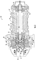
Figure 2 is a partially schematic view of an example compressor from the chiller system ofFigure 1 . -
Figure 3A is an enlarged view of an example first stage impeller with a first seal assembly in a first position. -
Figure 3B is an enlarged view of the example first stage impeller with the first seal assembly in a second position. -
Figure 4A is an enlarged view of an example second stage impeller with a second and third seal assembly in a first position. -
Figure 4B is an enlarged view of the example second stage impeller with the second and third seal assembly in a second position. -
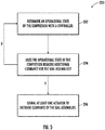
Figure 5 illustrates a flow diagram for an example method of operating the compressor ofFigure 1 . -
Figure 1 shows avapor compression system 20. The exemplaryvapor compression system 20 is a chiller system. Thesystem 20 includes acentrifugal compressor 22 having a suction port (inlet) 24 and a discharge port (outlet) 26. The system further includes afirst heat exchanger 28 in a normal operating mode being a heat rejection heat exchanger (e.g., a gas cooler or condenser). In an exemplary system, thefirst heat exchanger 28 is a refrigerant-water heat exchanger formed bytube bundles condenser unit 34 where the refrigerant is cooled by an external water flow. Afloat valve 36 controls flow through the condenser outlet from a subcooler chamber surrounding thesubcooler bundle 32. - The system further includes a second heat exchanger 38 (in the normal mode a heat absorption heat exchanger or evaporator). In the exemplary system, the
second heat exchanger 38 is a refrigerant-water heat exchanger formed by atube bundle 40 for chilling a chilled water flow within achiller unit 42. Thechiller unit 42 includes arefrigerant distributor 44. Anexpansion device 46 is downstream of the compressor and upstream of theevaporator 38 along the normal mode refrigerant flowpath 48 (the flowpath being partially surrounded by associated piping, etc.). - A hot
gas bypass valve 50 is positioned along abypass flowpath branch 52 extending between a first location downstream of theoutlet 26 and upstream of anisolation valve 54 and a second location upstream of the inlet of the cooler and downstream of theexpansion device 46. - As shown in
Figure 2 , thecompressor 22 is contained within anexemplary housing assembly 56. Thehousing assembly 56 contains anelectric motor 58 for driving afirst stage impeller 60 and asecond stage impeller 62. Theelectric motor 58 drives the first andsecond stage impellers inlet 24, compress the fluid, and discharge the fluid from theoutlet 26. In the illustrated example, the first andsecond stage impellers electric motor 58. - The
housing assembly 56 defines amotor compartment 64 containing astator 66 and arotor 68 of theelectric motor 58. In the illustrated example, therotor 68 is located partially within thestator 66 and is mounted for rotation about a rotor axis A for driving the first andsecond stage impellers rotor 68 is supported radially relative to thehousing assembly 56 with a radial supportelectromagnetic bearing system 70 located on each opposing axial side of theelectric motor 58. Additionally, therotor 68 is supported axially relative to thehousing assembly 56 with an axial thrustelectromagnetic bearing system 72 located on each opposing axial side of theelectric motor 58. The first andsecond stage impellers rotor 68 as a unit about the rotor axis A. In this disclosure, axial or axially and radial or radially is in relation to the rotor axis A unless stated otherwise. - As shown in
Figure 2 , fluid enters thecompressor 22 through theinlet 24. Between theinlet 24 and aninlet 80 of thefirst stage impeller 60, thecompressor 22 includes a controllable inlet guide vane (IGV)array 82 for controlling an amount of fluid entering thecompressor 22. Anoutlet 84 of thefirst stage impeller 60 is fluidly connected with aninlet 86 of thesecond stage impeller 62 through afluid passageway 88. Thefluid passageway 88 extends radially outward from theoutlet 84 of thefirst stage impeller 60 and turns back radially inward to join theinlet 86 of thesecond stage impeller 62. Anoutlet 90 of thesecond stage impeller 62 is fluidly connected to anoutlet plenum 92 through afluid passageway 94. - During operation of the
compressor 22, it is necessary to create a seal between portions of the first andsecond stage impellers housing assembly 56. In particular, thefirst stage impeller 60 is sealed with afirst seal assembly 96 and thesecond impeller stage 62 is sealed with asecond seal assembly 98 and athird seal assembly 100. - As shown in
Figures 3A-3B , thefirst seal assembly 96 includes a steppedseal land 102 forming a circumferential ring on a radially outer side of theinlet 80 to thefirst stage impeller 60. In the illustrated example, theseal land 102 includessteps compressor 22. - The
first seal assembly 96 also includes aseal 104 forming a complete ring that includes a corresponding number ofseal projections steps seal land 102. Theseal projections seal 104 is sealed relative to a portion of thehousing assembly 56 through an O-ring 106. - During operation of the
compressor 22, thefirst seal assembly 96 is located in the first position as shown inFigure 3A with thefirst seal 104 located in an axially downstream position with theprojections steps seal land 102. The configuration ofFigure 3A creates a labyrinth seal with theprojections steps - When the
compressor 22 is starting up or shutting down, at least oneactuator 108 moves theseal 104 to an axially forward position such that theprojections steps seal 104 and theseal land 102 to prevent theseal 104 from contacting theseal land 102 when theelectromagnetic bearings shaft 76. This configuration reduces leakage of fluid between a forward end of thefirst stage impeller 60 and thehousing assembly 56 to provide an increase in efficiency of thecompressor 22 during normal operating conditions. - As shown in
Figures 4A-4B , the second andthird seal assemblies second stage impeller 62, respectively. Thesecond seal assembly 98 includes a steppedseal land 110 forming a circumferential ring on a radially outer side of theinlet 86 to thesecond stage impeller 62. In the illustrated example, theseal land 110 includessteps compressor 22. - The
second seal assembly 98 also includes aseal 112 that includes a corresponding number ofseal projections steps seal land 110. Theseal projections seal 112 is sealed relative to a portion of thehousing assembly 56 through an O-ring 114. - During operation of the
compressor 22, thesecond seal assembly 98 is located in a first position as shown inFigure 4A with thefirst seal 112 forming a complete ring located in an axially downstream position with theprojections steps second seal land 110. The configuration ofFigure 4A creates a labyrinth seal with theprojections steps - When the
compressor 22 is starting up or shutting down, at least oneactuator 116 moves theseal 112 to an axially forward position such that theprojections steps seal 112 and theseal land 110 to prevent theseal 112 from contacting theseal land 110 when theelectromagnetic bearings shaft 76. This configuration reduces leakage of fluid between a forward end of thesecond stage impeller 62 and thehousing assembly 56 to provide an increase in efficiency of thecompressor 22 during normal operating conditions. - The
third seal assembly 100 includes a steppedseal land 118 forming a circumferential ring on an axially aft side of theoutlet 90 to thesecond stage impeller 62. In the illustrated example, theseal land 118 includessteps compressor 22. - The
third seal assembly 100 also includes aseal 120 that includes a corresponding number ofseal projections steps seal land 118. Theseal projections seal 118 is sealed relative to a portion of thehousing assembly 56 through an O-ring 122. - During operation of the
compressor 22, thethird seal assembly 100 is located in a first position as shown inFigure 4A with thethird seal 120 forming a complete ring located in an axially downstream position with theprojections steps second seal land 110. The configuration ofFigure 4A creates a labyrinth seal with theprojections steps - When the
compressor 22 is starting up or shutting down, at least oneactuator 124 moves theseal 120 to an axially forward position such that theprojections steps seal 120 and theseal land 118 to prevent theseal 120 from contacting theseal land 118 when theelectromagnetic bearings shaft 76. This configuration reduces leakage of fluid between an aft portion of thesecond stage impeller 62 and thehousing assembly 56 to provide an increase in efficiency of thecompressor 22 during normal operating conditions. - During operation of the
compressor 22, a controller 130 (Figure 1 ) determines an operational state of thecompressor 22 as shown in the method of operating thecompressor 200 inFigure 5 . (Step 202). Thecontroller 130 will then determine if the operational state of thecompressor 22 requires increased clearance in the first, second, andthird seal assemblies compressor 22 is not in an operation state that requires additional clearance, thecontroller 130 will continue to monitor for changes in the operational state of thecompressor 22. - If the
controller 130 determines that thecompressor 22 is in an operational state that requires additional clearance, thecontroller 130 sends a signal to increase clearance between the first, second, andthird seals controller 130 is sent to theactuators third seals controller 130 is sent to the actuator 126 to move theshaft 76 axially as discussed above without moving the first, second, andthird seals housing assembly 56. - The preceding description is exemplary rather than limiting in nature. Variations and modifications to the disclosed examples may become apparent to those skilled in the art that do not necessarily depart from the essence of this disclosure. The scope of legal protection given to this disclosure can only be determined by studying the following claims.
Claims (15)
- A seal assembly for a compressor comprising:at least one impeller;at least one seal land associated with the impeller including a plurality of radially stepped surfaces;a seal associated with each of the at least one seal lands, wherein the seal includes a plurality of radially stepped projections corresponding to the plurality of radially stepped surfaces on the at least one seal land; andat least one actuator configured to move the at least one seal land relative to the seal.
- The seal assembly of claim 1, wherein the at least one actuator is configured to move the seal between a first axial position and a second different axial position.
- The seal assembly of claim 1 or 2, wherein the at least one seal land is attached to one of the impeller and a housing assembly and the seal attached to the other of the impeller and the housing assembly.
- The seal assembly of claim 1, 2 or 3, wherein the plurality of radially stepped projections include distal ends with an increasing radial dimension in a first axial direction and adjacent ones of the plurality of radially stepped projections are separated by a trough.
- The seal assembly of claim 4, wherein the plurality of radially stepped surfaces include an increasing radial dimension in the first axial direction.
- The seal assembly of claim 5, wherein the first axial direction is an axially aft direction.
- The seal assembly of any preceding claim, wherein the seal is fixed relative to a housing assembly of the compressor and the at least one seal land is fixed relative to the impeller.
- The seal assembly of any preceding claim, wherein the plurality of radially stepped surfaces include three radially stepped surfaces and the plurality of radially stepped projections include three radially stepped projections.
- A compressor assembly comprising:at least one seal assembly as claimed in any preceding claim;a shaft in driving engagement with the at least one impeller; andat least one electromagnetic bearing supporting the shaft.
- The compressor assembly of claim 9, wherein the at least one electromagnetic bearing includes at least one radial support electromagnetic bearing system and at least one axial thrust electromagnetic bearing system.
- The compressor assembly of claim 9 or 10, wherein the plurality of radially stepped projections include distal ends with an increasing radial dimension in a first axial direction.
- The compressor assembly of claim 11, wherein the plurality of radially stepped surfaces include an increasing radial dimension in the first axial direction and adjacent ones of the plurality of radially stepped projections are separated by a trough.
- The compressor assembly of claim 9, wherein the at least one impeller includes a first stage impeller and a second stage impeller and the at least one seal assembly includes a first seal assembly associated with the first stage impeller and a second and third seal assembly associated with the second stage impeller; optionally
wherein the first seal assembly is located on an axially upstream side of the first stage impeller, the second seal assembly is located on an axially upstream side of the second stage impeller, and the third seal assembly is located on an axially downstream side of the second stage impeller. - A method of operating a compressor comprising:supporting a shaft in the compressor with at least one electromagnetic bearing;determining a seal clearance based on an operating condition of the compressor; andincreasing the seal clearance based on the operating condition by creating axial movement between a seal land attached to one of an impeller and a housing assembly and a seal attached to the other of the impeller and the housing assembly.
- The method of claim 14, being for operating a compressor with a seal assembly as claimed in any of claims 1 to 13, and/or wherein the operating condition includes at least one of a start-up or a shut-down condition for the compressor to increase seal clearance.
Applications Claiming Priority (1)
| Application Number | Priority Date | Filing Date | Title |
|---|---|---|---|
| US201962843773P | 2019-05-06 | 2019-05-06 |
Publications (2)
| Publication Number | Publication Date |
|---|---|
| EP3739217A1 true EP3739217A1 (en) | 2020-11-18 |
| EP3739217B1 EP3739217B1 (en) | 2022-07-13 |
Family
ID=70470857
Family Applications (1)
| Application Number | Title | Priority Date | Filing Date |
|---|---|---|---|
| EP20171512.5A Active EP3739217B1 (en) | 2019-05-06 | 2020-04-27 | Seal assembly for compressor |
Country Status (3)
| Country | Link |
|---|---|
| US (1) | US12372099B2 (en) |
| EP (1) | EP3739217B1 (en) |
| CN (1) | CN111894890B (en) |
Families Citing this family (4)
| Publication number | Priority date | Publication date | Assignee | Title |
|---|---|---|---|---|
| US11692557B2 (en) * | 2021-01-04 | 2023-07-04 | Danfoss A/S | Step seal for refrigerant compressors |
| CN113864211A (en) * | 2021-08-19 | 2021-12-31 | 青岛海尔智能技术研发有限公司 | Magnetic suspension pump, refrigeration equipment with same and air conditioner outdoor unit |
| FR3132276A1 (en) * | 2022-01-28 | 2023-08-04 | Safran Electronics & Defense | Movement transmission device |
| WO2026002691A1 (en) * | 2024-06-28 | 2026-01-02 | Tetra Laval Holdings & Finance S.A. | Compressor device for a pressurization system of a packaging machine configured to produce sealed packages containing a pourable food product |
Citations (4)
| Publication number | Priority date | Publication date | Assignee | Title |
|---|---|---|---|---|
| DE3513116A1 (en) * | 1985-04-12 | 1986-10-23 | M.A.N. Maschinenfabrik Augsburg-Nürnberg AG, 8500 Nürnberg | Controlled seal on centrifugal pump impellers |
| JPH11257293A (en) * | 1998-03-11 | 1999-09-21 | Kobe Steel Ltd | Control device of centrifugal compressor |
| EP2678569A1 (en) * | 2011-07-15 | 2014-01-01 | Carrier Corporation | Compressor clearance control |
| US20140169954A1 (en) * | 2011-07-26 | 2014-06-19 | Giuseppe Iurisci | Centrifugal impeller and turbomachine |
Family Cites Families (24)
| Publication number | Priority date | Publication date | Assignee | Title |
|---|---|---|---|---|
| FR2528127A1 (en) * | 1982-06-04 | 1983-12-09 | Creusot Loire | HIGH-SPEED INTEGRATED ELECTRIC CENTRIFUGAL MOTORCYMO COMPRESSOR |
| JPS6098196A (en) | 1983-11-02 | 1985-06-01 | Hitachi Ltd | Labyrinth seal device for centrifugal impeller |
| US5190440A (en) * | 1991-03-11 | 1993-03-02 | Dresser-Rand Company | Swirl control labyrinth seal |
| US5547350A (en) | 1994-12-15 | 1996-08-20 | Dresser-Rand Company | Modular shaftless compressor |
| JP2002228013A (en) * | 2001-02-01 | 2002-08-14 | Mitsubishi Heavy Ind Ltd | Acc type labyrinth seal |
| US6935838B1 (en) | 2003-03-19 | 2005-08-30 | Hi-Bar Blowers, Inc. | High pressure multi-stage centrifugal blower |
| GB0513654D0 (en) * | 2005-07-02 | 2005-08-10 | Rolls Royce Plc | Variable displacement turbine liner |
| US9261104B2 (en) | 2005-09-19 | 2016-02-16 | Ingersoll-Rand Company | Air blower for a motor-driven compressor |
| CN101268284A (en) | 2005-09-19 | 2008-09-17 | 英格索尔-兰德公司 | impeller of centrifugal compressor |
| US20070065277A1 (en) | 2005-09-19 | 2007-03-22 | Ingersoll-Rand Company | Centrifugal compressor including a seal system |
| US7775763B1 (en) * | 2007-06-21 | 2010-08-17 | Florida Turbine Technologies, Inc. | Centrifugal pump with rotor thrust balancing seal |
| KR100878460B1 (en) * | 2007-07-06 | 2009-01-13 | 한국과학기술연구원 | Labyrinth seal |
| JP4655123B2 (en) | 2008-08-07 | 2011-03-23 | 株式会社日立プラントテクノロジー | Centrifugal compressor |
| JP2012057726A (en) | 2010-09-09 | 2012-03-22 | Mitsubishi Heavy Ind Ltd | Seal structure and centrifugal compressor |
| ITFI20120124A1 (en) | 2012-06-19 | 2013-12-20 | Nuovo Pignone Srl | "CENTRIFUGAL COMPRESSOR IMPELLER COOLING" |
| EP2749771B1 (en) | 2012-12-27 | 2020-04-22 | Thermodyn | Device for generating a dynamic axial thrust to balance the overall axial thrust of a radial rotating machine |
| JP6090926B2 (en) * | 2013-05-30 | 2017-03-08 | 三菱重工業株式会社 | Turbo compressor and turbo refrigerator using the same |
| ITFI20130204A1 (en) | 2013-09-03 | 2015-03-04 | Nuovo Pignone Srl | "FAN-COOLED ELECTRICAL MACHINE WITH AXIAL THRUST COMPENSATION" |
| ITFI20130237A1 (en) | 2013-10-14 | 2015-04-15 | Nuovo Pignone Srl | "SEALING CLEARANCE CONTROL IN TURBOMACHINES" |
| US20150104335A1 (en) | 2013-10-15 | 2015-04-16 | Solar Turbines Incorporated | Internal-driven compressor having a powered compressor rotor |
| US10408226B2 (en) | 2016-05-26 | 2019-09-10 | Rolls-Royce Corporation | Segregated impeller shroud for clearance control in a centrifugal compressor |
| US10208762B2 (en) | 2016-10-10 | 2019-02-19 | Solar Turbines Incorporated | Swirl brakes for compressors with teeth-on-rotor seals |
| US10344612B2 (en) | 2017-01-13 | 2019-07-09 | United Technologies Corporation | Compact advanced passive tip clearance control |
| US10760442B2 (en) * | 2018-01-12 | 2020-09-01 | Raytheon Technologies Corporation | Non-contact seal with angled land |
-
2020
- 2020-04-10 US US16/845,743 patent/US12372099B2/en active Active
- 2020-04-27 EP EP20171512.5A patent/EP3739217B1/en active Active
- 2020-05-06 CN CN202010371616.5A patent/CN111894890B/en active Active
Patent Citations (4)
| Publication number | Priority date | Publication date | Assignee | Title |
|---|---|---|---|---|
| DE3513116A1 (en) * | 1985-04-12 | 1986-10-23 | M.A.N. Maschinenfabrik Augsburg-Nürnberg AG, 8500 Nürnberg | Controlled seal on centrifugal pump impellers |
| JPH11257293A (en) * | 1998-03-11 | 1999-09-21 | Kobe Steel Ltd | Control device of centrifugal compressor |
| EP2678569A1 (en) * | 2011-07-15 | 2014-01-01 | Carrier Corporation | Compressor clearance control |
| US20140169954A1 (en) * | 2011-07-26 | 2014-06-19 | Giuseppe Iurisci | Centrifugal impeller and turbomachine |
Also Published As
| Publication number | Publication date |
|---|---|
| US20200355194A1 (en) | 2020-11-12 |
| EP3739217B1 (en) | 2022-07-13 |
| US12372099B2 (en) | 2025-07-29 |
| CN111894890A (en) | 2020-11-06 |
| CN111894890B (en) | 2022-04-29 |
Similar Documents
| Publication | Publication Date | Title |
|---|---|---|
| EP3739217B1 (en) | Seal assembly for compressor | |
| EP3488112B1 (en) | Chiller system with centrifugal compressor and magnetic bearing backup system | |
| EP3494309B1 (en) | Rotary compressor with impeller distance control device and impeller distance control method for rotary compressors | |
| EP0550381B1 (en) | Back pressure valve | |
| CN103635697B (en) | Compressor Surge Detection | |
| CN108779779B (en) | Centrifugal compressor | |
| US7704056B2 (en) | Two-stage vapor cycle compressor | |
| EP1961972A2 (en) | Two-stage vapor cycle compressor | |
| EP2823240B1 (en) | High pressure ratio multi-stage centrifugal compressor | |
| US20140182317A1 (en) | Economized Centrifugal Compressor | |
| US10968919B2 (en) | Two-stage centrifugal compressor | |
| EP3123082B1 (en) | Chiller compressor rolling bearings with squeeze film dampers | |
| CA2926814A1 (en) | Sealing clearance control in turbomachines | |
| US11460041B2 (en) | Turbo compressor | |
| KR20150078944A (en) | A turbo compressor and a turbo chiller including the same | |
| JP2024130526A (en) | Freezer | |
| WO2026024384A1 (en) | Refrigerant compressor including configuration of axial and centrifugal stages | |
| Larralde et al. | Selection of gas compressors: part 4 |
Legal Events
| Date | Code | Title | Description |
|---|---|---|---|
| PUAI | Public reference made under article 153(3) epc to a published international application that has entered the european phase |
Free format text: ORIGINAL CODE: 0009012 |
|
| STAA | Information on the status of an ep patent application or granted ep patent |
Free format text: STATUS: THE APPLICATION HAS BEEN PUBLISHED |
|
| AK | Designated contracting states |
Kind code of ref document: A1 Designated state(s): AL AT BE BG CH CY CZ DE DK EE ES FI FR GB GR HR HU IE IS IT LI LT LU LV MC MK MT NL NO PL PT RO RS SE SI SK SM TR |
|
| AX | Request for extension of the european patent |
Extension state: BA ME |
|
| STAA | Information on the status of an ep patent application or granted ep patent |
Free format text: STATUS: REQUEST FOR EXAMINATION WAS MADE |
|
| 17P | Request for examination filed |
Effective date: 20210513 |
|
| RBV | Designated contracting states (corrected) |
Designated state(s): AL AT BE BG CH CY CZ DE DK EE ES FI FR GB GR HR HU IE IS IT LI LT LU LV MC MK MT NL NO PL PT RO RS SE SI SK SM TR |
|
| STAA | Information on the status of an ep patent application or granted ep patent |
Free format text: STATUS: EXAMINATION IS IN PROGRESS |
|
| 17Q | First examination report despatched |
Effective date: 20211007 |
|
| REG | Reference to a national code |
Ref country code: DE Ref legal event code: R079 Ref document number: 602020003956 Country of ref document: DE Free format text: PREVIOUS MAIN CLASS: F04D0029160000 Ipc: F04D0017120000 |
|
| GRAP | Despatch of communication of intention to grant a patent |
Free format text: ORIGINAL CODE: EPIDOSNIGR1 |
|
| STAA | Information on the status of an ep patent application or granted ep patent |
Free format text: STATUS: GRANT OF PATENT IS INTENDED |
|
| RIC1 | Information provided on ipc code assigned before grant |
Ipc: F04D 29/058 20060101ALI20220217BHEP Ipc: F04D 29/16 20060101ALI20220217BHEP Ipc: F04D 27/02 20060101ALI20220217BHEP Ipc: F04D 17/12 20060101AFI20220217BHEP |
|
| INTG | Intention to grant announced |
Effective date: 20220322 |
|
| RIN1 | Information on inventor provided before grant (corrected) |
Inventor name: SISHTLA, VISHNU M |
|
| GRAS | Grant fee paid |
Free format text: ORIGINAL CODE: EPIDOSNIGR3 |
|
| GRAA | (expected) grant |
Free format text: ORIGINAL CODE: 0009210 |
|
| STAA | Information on the status of an ep patent application or granted ep patent |
Free format text: STATUS: THE PATENT HAS BEEN GRANTED |
|
| AK | Designated contracting states |
Kind code of ref document: B1 Designated state(s): AL AT BE BG CH CY CZ DE DK EE ES FI FR GB GR HR HU IE IS IT LI LT LU LV MC MK MT NL NO PL PT RO RS SE SI SK SM TR |
|
| REG | Reference to a national code |
Ref country code: CH Ref legal event code: EP |
|
| REG | Reference to a national code |
Ref country code: DE Ref legal event code: R096 Ref document number: 602020003956 Country of ref document: DE |
|
| REG | Reference to a national code |
Ref country code: NL Ref legal event code: FP |
|
| REG | Reference to a national code |
Ref country code: AT Ref legal event code: REF Ref document number: 1504423 Country of ref document: AT Kind code of ref document: T Effective date: 20220815 |
|
| REG | Reference to a national code |
Ref country code: IE Ref legal event code: FG4D |
|
| REG | Reference to a national code |
Ref country code: LT Ref legal event code: MG9D |
|
| PG25 | Lapsed in a contracting state [announced via postgrant information from national office to epo] |
Ref country code: SE Free format text: LAPSE BECAUSE OF FAILURE TO SUBMIT A TRANSLATION OF THE DESCRIPTION OR TO PAY THE FEE WITHIN THE PRESCRIBED TIME-LIMIT Effective date: 20220713 Ref country code: RS Free format text: LAPSE BECAUSE OF FAILURE TO SUBMIT A TRANSLATION OF THE DESCRIPTION OR TO PAY THE FEE WITHIN THE PRESCRIBED TIME-LIMIT Effective date: 20220713 Ref country code: PT Free format text: LAPSE BECAUSE OF FAILURE TO SUBMIT A TRANSLATION OF THE DESCRIPTION OR TO PAY THE FEE WITHIN THE PRESCRIBED TIME-LIMIT Effective date: 20221114 Ref country code: NO Free format text: LAPSE BECAUSE OF FAILURE TO SUBMIT A TRANSLATION OF THE DESCRIPTION OR TO PAY THE FEE WITHIN THE PRESCRIBED TIME-LIMIT Effective date: 20221013 Ref country code: LV Free format text: LAPSE BECAUSE OF FAILURE TO SUBMIT A TRANSLATION OF THE DESCRIPTION OR TO PAY THE FEE WITHIN THE PRESCRIBED TIME-LIMIT Effective date: 20220713 Ref country code: LT Free format text: LAPSE BECAUSE OF FAILURE TO SUBMIT A TRANSLATION OF THE DESCRIPTION OR TO PAY THE FEE WITHIN THE PRESCRIBED TIME-LIMIT Effective date: 20220713 Ref country code: FI Free format text: LAPSE BECAUSE OF FAILURE TO SUBMIT A TRANSLATION OF THE DESCRIPTION OR TO PAY THE FEE WITHIN THE PRESCRIBED TIME-LIMIT Effective date: 20220713 Ref country code: ES Free format text: LAPSE BECAUSE OF FAILURE TO SUBMIT A TRANSLATION OF THE DESCRIPTION OR TO PAY THE FEE WITHIN THE PRESCRIBED TIME-LIMIT Effective date: 20220713 |
|
| REG | Reference to a national code |
Ref country code: AT Ref legal event code: MK05 Ref document number: 1504423 Country of ref document: AT Kind code of ref document: T Effective date: 20220713 |
|
| PG25 | Lapsed in a contracting state [announced via postgrant information from national office to epo] |
Ref country code: PL Free format text: LAPSE BECAUSE OF FAILURE TO SUBMIT A TRANSLATION OF THE DESCRIPTION OR TO PAY THE FEE WITHIN THE PRESCRIBED TIME-LIMIT Effective date: 20220713 Ref country code: IS Free format text: LAPSE BECAUSE OF FAILURE TO SUBMIT A TRANSLATION OF THE DESCRIPTION OR TO PAY THE FEE WITHIN THE PRESCRIBED TIME-LIMIT Effective date: 20221113 Ref country code: HR Free format text: LAPSE BECAUSE OF FAILURE TO SUBMIT A TRANSLATION OF THE DESCRIPTION OR TO PAY THE FEE WITHIN THE PRESCRIBED TIME-LIMIT Effective date: 20220713 Ref country code: GR Free format text: LAPSE BECAUSE OF FAILURE TO SUBMIT A TRANSLATION OF THE DESCRIPTION OR TO PAY THE FEE WITHIN THE PRESCRIBED TIME-LIMIT Effective date: 20221014 |
|
| REG | Reference to a national code |
Ref country code: DE Ref legal event code: R097 Ref document number: 602020003956 Country of ref document: DE |
|
| PG25 | Lapsed in a contracting state [announced via postgrant information from national office to epo] |
Ref country code: SM Free format text: LAPSE BECAUSE OF FAILURE TO SUBMIT A TRANSLATION OF THE DESCRIPTION OR TO PAY THE FEE WITHIN THE PRESCRIBED TIME-LIMIT Effective date: 20220713 Ref country code: RO Free format text: LAPSE BECAUSE OF FAILURE TO SUBMIT A TRANSLATION OF THE DESCRIPTION OR TO PAY THE FEE WITHIN THE PRESCRIBED TIME-LIMIT Effective date: 20220713 Ref country code: DK Free format text: LAPSE BECAUSE OF FAILURE TO SUBMIT A TRANSLATION OF THE DESCRIPTION OR TO PAY THE FEE WITHIN THE PRESCRIBED TIME-LIMIT Effective date: 20220713 Ref country code: CZ Free format text: LAPSE BECAUSE OF FAILURE TO SUBMIT A TRANSLATION OF THE DESCRIPTION OR TO PAY THE FEE WITHIN THE PRESCRIBED TIME-LIMIT Effective date: 20220713 Ref country code: AT Free format text: LAPSE BECAUSE OF FAILURE TO SUBMIT A TRANSLATION OF THE DESCRIPTION OR TO PAY THE FEE WITHIN THE PRESCRIBED TIME-LIMIT Effective date: 20220713 |
|
| PLBE | No opposition filed within time limit |
Free format text: ORIGINAL CODE: 0009261 |
|
| STAA | Information on the status of an ep patent application or granted ep patent |
Free format text: STATUS: NO OPPOSITION FILED WITHIN TIME LIMIT |
|
| PG25 | Lapsed in a contracting state [announced via postgrant information from national office to epo] |
Ref country code: SK Free format text: LAPSE BECAUSE OF FAILURE TO SUBMIT A TRANSLATION OF THE DESCRIPTION OR TO PAY THE FEE WITHIN THE PRESCRIBED TIME-LIMIT Effective date: 20220713 Ref country code: EE Free format text: LAPSE BECAUSE OF FAILURE TO SUBMIT A TRANSLATION OF THE DESCRIPTION OR TO PAY THE FEE WITHIN THE PRESCRIBED TIME-LIMIT Effective date: 20220713 |
|
| 26N | No opposition filed |
Effective date: 20230414 |
|
| PG25 | Lapsed in a contracting state [announced via postgrant information from national office to epo] |
Ref country code: AL Free format text: LAPSE BECAUSE OF FAILURE TO SUBMIT A TRANSLATION OF THE DESCRIPTION OR TO PAY THE FEE WITHIN THE PRESCRIBED TIME-LIMIT Effective date: 20220713 |
|
| P01 | Opt-out of the competence of the unified patent court (upc) registered |
Effective date: 20230527 |
|
| PG25 | Lapsed in a contracting state [announced via postgrant information from national office to epo] |
Ref country code: SI Free format text: LAPSE BECAUSE OF FAILURE TO SUBMIT A TRANSLATION OF THE DESCRIPTION OR TO PAY THE FEE WITHIN THE PRESCRIBED TIME-LIMIT Effective date: 20220713 |
|
| REG | Reference to a national code |
Ref country code: CH Ref legal event code: PL |
|
| REG | Reference to a national code |
Ref country code: NL Ref legal event code: MM Effective date: 20230501 |
|
| PG25 | Lapsed in a contracting state [announced via postgrant information from national office to epo] |
Ref country code: LU Free format text: LAPSE BECAUSE OF NON-PAYMENT OF DUE FEES Effective date: 20230427 |
|
| REG | Reference to a national code |
Ref country code: BE Ref legal event code: MM Effective date: 20230430 |
|
| PG25 | Lapsed in a contracting state [announced via postgrant information from national office to epo] |
Ref country code: MC Free format text: LAPSE BECAUSE OF FAILURE TO SUBMIT A TRANSLATION OF THE DESCRIPTION OR TO PAY THE FEE WITHIN THE PRESCRIBED TIME-LIMIT Effective date: 20220713 |
|
| PG25 | Lapsed in a contracting state [announced via postgrant information from national office to epo] |
Ref country code: NL Free format text: LAPSE BECAUSE OF NON-PAYMENT OF DUE FEES Effective date: 20230501 Ref country code: MC Free format text: LAPSE BECAUSE OF FAILURE TO SUBMIT A TRANSLATION OF THE DESCRIPTION OR TO PAY THE FEE WITHIN THE PRESCRIBED TIME-LIMIT Effective date: 20220713 Ref country code: LI Free format text: LAPSE BECAUSE OF NON-PAYMENT OF DUE FEES Effective date: 20230430 Ref country code: IT Free format text: LAPSE BECAUSE OF FAILURE TO SUBMIT A TRANSLATION OF THE DESCRIPTION OR TO PAY THE FEE WITHIN THE PRESCRIBED TIME-LIMIT Effective date: 20220713 Ref country code: CH Free format text: LAPSE BECAUSE OF NON-PAYMENT OF DUE FEES Effective date: 20230430 |
|
| REG | Reference to a national code |
Ref country code: IE Ref legal event code: MM4A |
|
| PG25 | Lapsed in a contracting state [announced via postgrant information from national office to epo] |
Ref country code: BE Free format text: LAPSE BECAUSE OF NON-PAYMENT OF DUE FEES Effective date: 20230430 |
|
| PG25 | Lapsed in a contracting state [announced via postgrant information from national office to epo] |
Ref country code: IE Free format text: LAPSE BECAUSE OF NON-PAYMENT OF DUE FEES Effective date: 20230427 |
|
| PG25 | Lapsed in a contracting state [announced via postgrant information from national office to epo] |
Ref country code: IE Free format text: LAPSE BECAUSE OF NON-PAYMENT OF DUE FEES Effective date: 20230427 |
|
| PG25 | Lapsed in a contracting state [announced via postgrant information from national office to epo] |
Ref country code: BG Free format text: LAPSE BECAUSE OF FAILURE TO SUBMIT A TRANSLATION OF THE DESCRIPTION OR TO PAY THE FEE WITHIN THE PRESCRIBED TIME-LIMIT Effective date: 20220713 |
|
| PG25 | Lapsed in a contracting state [announced via postgrant information from national office to epo] |
Ref country code: BG Free format text: LAPSE BECAUSE OF FAILURE TO SUBMIT A TRANSLATION OF THE DESCRIPTION OR TO PAY THE FEE WITHIN THE PRESCRIBED TIME-LIMIT Effective date: 20220713 |
|
| GBPC | Gb: european patent ceased through non-payment of renewal fee |
Effective date: 20240427 |
|
| PG25 | Lapsed in a contracting state [announced via postgrant information from national office to epo] |
Ref country code: GB Free format text: LAPSE BECAUSE OF NON-PAYMENT OF DUE FEES Effective date: 20240427 |
|
| PG25 | Lapsed in a contracting state [announced via postgrant information from national office to epo] |
Ref country code: GB Free format text: LAPSE BECAUSE OF NON-PAYMENT OF DUE FEES Effective date: 20240427 |
|
| PGFP | Annual fee paid to national office [announced via postgrant information from national office to epo] |
Ref country code: DE Payment date: 20250319 Year of fee payment: 6 |
|
| PG25 | Lapsed in a contracting state [announced via postgrant information from national office to epo] |
Ref country code: CY Free format text: LAPSE BECAUSE OF FAILURE TO SUBMIT A TRANSLATION OF THE DESCRIPTION OR TO PAY THE FEE WITHIN THE PRESCRIBED TIME-LIMIT; INVALID AB INITIO Effective date: 20200427 |
|
| PG25 | Lapsed in a contracting state [announced via postgrant information from national office to epo] |
Ref country code: HU Free format text: LAPSE BECAUSE OF FAILURE TO SUBMIT A TRANSLATION OF THE DESCRIPTION OR TO PAY THE FEE WITHIN THE PRESCRIBED TIME-LIMIT; INVALID AB INITIO Effective date: 20200427 |
|
| PG25 | Lapsed in a contracting state [announced via postgrant information from national office to epo] |
Ref country code: TR Free format text: LAPSE BECAUSE OF FAILURE TO SUBMIT A TRANSLATION OF THE DESCRIPTION OR TO PAY THE FEE WITHIN THE PRESCRIBED TIME-LIMIT Effective date: 20220713 |
|
| PGFP | Annual fee paid to national office [announced via postgrant information from national office to epo] |
Ref country code: FR Payment date: 20260320 Year of fee payment: 7 |