EP3739179A1 - Cooling system with a shroud assembly - Google Patents
Cooling system with a shroud assembly Download PDFInfo
- Publication number
- EP3739179A1 EP3739179A1 EP19461540.7A EP19461540A EP3739179A1 EP 3739179 A1 EP3739179 A1 EP 3739179A1 EP 19461540 A EP19461540 A EP 19461540A EP 3739179 A1 EP3739179 A1 EP 3739179A1
- Authority
- EP
- European Patent Office
- Prior art keywords
- fan
- shroud
- heat exchanger
- arms
- frame
- Prior art date
- Legal status (The legal status is an assumption and is not a legal conclusion. Google has not performed a legal analysis and makes no representation as to the accuracy of the status listed.)
- Withdrawn
Links
- 238000001816 cooling Methods 0.000 title claims abstract description 47
- 238000006073 displacement reaction Methods 0.000 claims abstract description 16
- 230000000295 complement effect Effects 0.000 claims description 4
- 239000002131 composite material Substances 0.000 claims description 4
- 239000004033 plastic Substances 0.000 claims description 3
- 238000011144 upstream manufacturing Methods 0.000 claims description 3
- 239000012080 ambient air Substances 0.000 description 8
- 239000012530 fluid Substances 0.000 description 7
- 239000003570 air Substances 0.000 description 3
- 238000010438 heat treatment Methods 0.000 description 3
- 239000000463 material Substances 0.000 description 3
- 238000004378 air conditioning Methods 0.000 description 2
- 238000009423 ventilation Methods 0.000 description 2
- -1 Polypropylene Polymers 0.000 description 1
- 239000004743 Polypropylene Substances 0.000 description 1
- 238000007664 blowing Methods 0.000 description 1
- 239000000284 extract Substances 0.000 description 1
- 239000000945 filler Substances 0.000 description 1
- 239000003365 glass fiber Substances 0.000 description 1
- 238000000034 method Methods 0.000 description 1
- 238000012986 modification Methods 0.000 description 1
- 230000004048 modification Effects 0.000 description 1
- 229920001155 polypropylene Polymers 0.000 description 1
- 230000035939 shock Effects 0.000 description 1
Images


Classifications
-
- F—MECHANICAL ENGINEERING; LIGHTING; HEATING; WEAPONS; BLASTING
- F01—MACHINES OR ENGINES IN GENERAL; ENGINE PLANTS IN GENERAL; STEAM ENGINES
- F01P—COOLING OF MACHINES OR ENGINES IN GENERAL; COOLING OF INTERNAL-COMBUSTION ENGINES
- F01P5/00—Pumping cooling-air or liquid coolants
- F01P5/02—Pumping cooling-air; Arrangements of cooling-air pumps, e.g. fans or blowers
- F01P5/06—Guiding or ducting air to, or from, ducted fans
-
- F—MECHANICAL ENGINEERING; LIGHTING; HEATING; WEAPONS; BLASTING
- F01—MACHINES OR ENGINES IN GENERAL; ENGINE PLANTS IN GENERAL; STEAM ENGINES
- F01P—COOLING OF MACHINES OR ENGINES IN GENERAL; COOLING OF INTERNAL-COMBUSTION ENGINES
- F01P5/00—Pumping cooling-air or liquid coolants
- F01P5/02—Pumping cooling-air; Arrangements of cooling-air pumps, e.g. fans or blowers
- F01P5/04—Pump-driving arrangements
- F01P2005/046—Pump-driving arrangements with electrical pump drive
-
- F—MECHANICAL ENGINEERING; LIGHTING; HEATING; WEAPONS; BLASTING
- F01—MACHINES OR ENGINES IN GENERAL; ENGINE PLANTS IN GENERAL; STEAM ENGINES
- F01P—COOLING OF MACHINES OR ENGINES IN GENERAL; COOLING OF INTERNAL-COMBUSTION ENGINES
- F01P2070/00—Details
- F01P2070/50—Details mounting fans to heat-exchangers
Definitions
- the present invention generally relates to a cooling system, and in particularly, to a shroud assembly to accommodate and support a fan of a cooling system.
- cooling systems are provided in a vehicle to maintain the temperature of an engine and a passenger cabin of the vehicle at an optimum level.
- the cooling systems may be a part of Heating Ventilation and Air Conditioning (HVAC) system.
- HVAC Heating Ventilation and Air Conditioning
- the cooling systems may include a radiator to exchange heat generated in the engine with the ambient air or the cooling system may include a condenser to reject heat extracted from the vehicle cabin to the ambient air.
- the radiator is connected with the engine through conduits, the conduits supply heat exchange fluid to the engine to carry away the heat from the engine, the heat exchange fluid getting heated in the process.
- a fan e.g., a blower
- the fan may be provided in a shroud assembly and tightly packed with the radiator core as shown in Fig. 1 , due to space constraints in the vehicle and to provide optimum ambient air to the radiator.
- Fig. 1 is a cross-sectional view of a radiator 10 provided with a conventional shroud assembly 12 having a fan 14. The shroud assembly 12 is mounted on the radiator 10 in a posterior position with respect to the radiator 10, and the fan 14 is provided in the shroud assembly 12.
- the shroud assembly 12 having arms coupled to a fan socket to provide rigid support to the fan 14.
- blades of the fan 14 may collide with the radiator 10 during vibration test of vehicle or when the vehicle is moving on an uneven terrain. Further, collision between the blades of the fan 14 and the radiator 10 may cause considerable damages to the blades of the fan 14 as well as the radiator 10.
- the arms of the shroud assembly 12 do not distribute the pressure generated by a load applied on the fan 14, collision between the blades of the fan 14 and the radiator 10 is unavoidable.
- the shroud assembly 12 is made of lighter and cheaper materials to meet market and customer requirements.
- the shroud assembly 12 is made of not so robust materials which may get damaged in high temperature and reduction young's modulus of the shroud assembly 12.
- such shroud assembly 12 tends to bend while during vibration test or any force applied thereon due to use of non-robust material, which leads to damage of the fan and the radiator.
- some elements or parameters may be indexed, such as a first element and a second element.
- this indexation is only meant to differentiate and name elements which are similar but not identical. No idea of priority should be inferred from such indexation, as these terms may be switched without betraying the invention. Additionally, this indexation does not imply any order in mounting or use of the elements of the invention.
- an embodiment of the invention herein provides a cooling system for a vehicle.
- the cooling system includes a heat exchanger and a shroud.
- the shroud is mounted to the heat exchanger at a posterior position with respect to the heat exchanger.
- the shroud further includes a frame, a fan socket, and a plurality of arms.
- the frame is provided at a first plane of the shroud to mount the shroud to the heat exchanger.
- the fan socket is provided at a second plane of the shroud to receive a motor of a fan, where the first plane and the second plane are parallelly spaced apart from each other.
- the plurality of arms is adapted to be coupled in between the frame and the fan socket to provide rigid support to the fan and minimize displacement of the fan.
- the plurality of arms coupled between the frame and the fan socket forms a dome shape to accommodate blades of the fan.
- at least one arm of the plurality of arms is bent to form an arc shape.
- the at least one arm of the plurality of arms is inclined at an angle to form a connection between the fan socket and the frame.
- the plurality of arms of the shroud is of plastic composites.
- the plurality of arms is adapted to distribute force, applied on the fan socket in a lateral axis, along a longitudinal axis of the plurality of arms.
- the fan is provided in between the shroud and the heat exchanger, and heat exchanger is a radiator of the vehicle.
- the frame further includes at least one locking element adapted to engage with at least one complementary groove provided on side walls of the heat exchanger.
- a shroud assembly for a heat exchanger.
- the shroud assembly includes a frame, a fan, and a fan socket.
- the frame is provided at a first plane of the shroud assembly and facilities mounting of the shroud assembly to the heat exchanger, where the frame is at a posterior position with respect to the heat exchanger.
- the fan having a motor is provided in between the frame and the heat exchanger.
- the fan socket is provided at a second plane of the shroud assembly to receive the motor of the fan, where the first plane and the second plane are parallelly spaced apart from each other.
- the plurality of arms is adapted to couple the frame and the fan socket to provide rigid support to the fan and minimize displacement of the fan.
- the plurality of arms coupled between the frame and the fan socket forms a dome shape to accommodate blades of the fan.
- the at least one arm of the plurality of arms is bent to form an arc shape.
- the at least one arm of the plurality of arms is inclined at an angle to form an connection between the fan socket and the frame.
- the shroud assembly is coupled to an upstream side of the heat exchanger
- the present invention relates to a cooling system for maintaining optimum temperature in a vehicle or for engine cooling.
- the cooling system can be integrated to a Heating Ventilation and Air-conditioning (HVAC) system to condition air inside a passenger cabin of the vehicle.
- HVAC Heating Ventilation and Air-conditioning
- the cooling system is adapted to extract heat generated in an engine and reject the same to the environment.
- the cooling system may include a heat exchanger, preferably a radiator, and a shroud assembly.
- the cooling system may further include other elements known to the persons skilled in the art.
- the shroud assembly is mounted on the heat exchanger at a posterior position with respect to the heat exchanger.
- the shroud assembly may include a frame mounted on the radiator and a fan socket provided in parallel planes spaced apart from each other.
- the fan socket and the frame are connected by a plurality of arms, which forms a dome shape.
- the plurality of arms forms a dome shape, displacement of a fan received in the fan socket towards the radiator is reduced even when the shroud assembly is subjected to any vibration or load.
- the plurality arms distribute the load or pressure to the frame of the shroud assembly, thereby preventing substantial movement of the fan. Therefore, collision between blades of the fan and the heat exchanger is avoided.
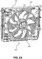
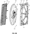
- Figs. 2A and 2B illustrate schematic views of a cooling system 200 for a vehicle, in accordance with an embodiment of the present invention.
- Fig. 2A illustrates a schematic view of the cooling system 200
- Fig. 2B illustrates an exploded view of the cooling system 200.
- the cooling system 200 may include a heat exchanger 102, and a shroud assembly 104, hereinafter referred to as shroud 104.
- shroud 104 may include other elements (not shown in Figs) required to perform cooling operation, as known to the persons skilled in the art.
- the heat exchanger 102 may be a radiator provided at an anterior portion of the vehicle.
- the heat exchanger 102 may be connected to an engine or evaporator of a HVAC system through conduits to receive heat exchange fluid.
- the heat exchange fluid received from the engine or the evaporator extracts heat generated in the engine or passenger cabin of the vehicle.
- the heat exchanger 102 enables heat exchange between the heat exchange fluid and the ambient air flowing thereon.
- the shroud 104 can be mounted on the heat exchanger 102 at a posterior position with the respect to the heat exchanger 102. In one embodiment, the shroud 104 can be positioned at an anterior position or the posterior position with respect to the heat exchanger 102 based on the type of fan used in the cooling system 200.
- the shroud 104 can be positioned at the anterior position with respect to the heat exchanger 102.
- the shroud 104 further includes a frame 202, a fan socket 204, and a plurality of arms 210.
- the frame 202 is provided at a first plane of the shroud 104
- the fan socket 204 is provided at a second plane of the shroud 104.
- the first plane of the frame 202 and second plane of the fan socket 204 will be explained in the forthcoming figures.
- the first plane and the second plane are parallelly spaced apart from each other.
- the cooling system 200 further includes a fan 206, preferably a blower, provided in the fan socket 204 to enable airflow on the heat exchanger 102.
- the fan 206 may receive ambient air from the environment and facilitate passing of the air through the heat exchanger 102, in case the shroud 104 is provided in the posterior position with respect to the heat exchanger 102.
- the fan 206 may blow the ambient air on the heat exchanger 102, in case the shroud 104 is provided in the anterior position with respect to the heat exchanger 102.
- the fan 206 includes a motor 208 provided with blades 212 to enable ambient airflow on the heat exchanger 102.
- the fan socket 204 is adapted to receive the motor 208 and the blades 212 of the fan 206 are accommodated adjacent to the plurality of arms 210.
- the fan 206 is provided in the fan socket 204 in such a way that the fan 206 is posterior to the heat exchanger 102 and anterior to the shroud 104. In other words, the fan 206 is provided in between the shroud 104 and the heat exchanger 102.
- the plurality of arms 210 forms a connection between the frame 202 and the fan socket 204 to provide rigid support to the fan 206 and minimize displacement of the fan 206 when any force or load is applied on the shroud 104.
- the plurality of arms 210 forms an angled connection when connecting the plurality of arms 210 between the frame 202 and the fan socket 204.
- the plurality of arms 210 distributes the force/pressure acting on the fan socket 204 to the edges of the frame 202, thereby minimizing displacement of the fan 206 towards the heat exchanger 102.
- the frame 202 further includes one or more locking elements 214 to mount the shroud 104 on the heat exchanger 102.
- the heat exchanger 102 may include one or more complementary grooves provided in side walls 216 of the heat exchanger 102. The one or more complementary grooves receive the one or more locking elements 214 to enable a connection between the shroud 104 and the heat exchanger 102.
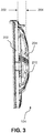
- Fig. 3 illustrates a side view of the shroud 104 of the cooling system 200 of Fig. 2A .
- the frame 202 of the shroud 104 is in the first plane 302, and the fan socket 204 is in the second plane 304.
- the first plane 302 is parallelly spaced from the second plane 304. In other words, the first plane 302 is laterally spaced from the second plane 304 of the shroud 104.
- the plurality of arms 210 is adapted to connect the fan socket 204 with the frame 202 to distribute the stress/load acting on the fan socket 204 to the frame 202.
- at least one arm of the plurality of arms 210 is bent to form an arc shape.
- the plurality of arms 210 coupled in between the frame 202 and the fan socket 204 forms a dome shape to accommodate the blades 212 of the fan 206.
- Figs 4A and 4B illustrate different views of the shroud 104 of the cooling system 200 of Fig. 1 .
- Fig. 4A illustrates a schematic view of the shroud 104 having the plurality of arms 210, in accordance to an embodiment of the present invention.
- the plurality of arms 210 is formed as dome shaped to accommodate the blades 212 of the fan 206.
- the plurality of arms 210 dissipates or distributes the force along longitudinal axis 404 of the plurality of arms 210, the force is ultimately transmitted to the frame 202.
- the plurality of arms 210 is formed as an arc shape and forms a connection between the fan socket 204 and the frame 202.
- Fig. 4B illustrates another schematic view of the shroud 104 having the plurality of arms 210, in accordance to another embodiment of the present invention.
- the plurality of arms 210 is angled arms to form a connection between the frame 202 and the fan socket 204 at an angle "a" marked as 406.
- the plurality of arms 210 is inclined at the angle 406 to form a connection between the fan socket 204 and the frame 202.
- the plurality of arms 210 connected between the frame 202 and the fan socket 204 forms an angle with respect to the frame 202.
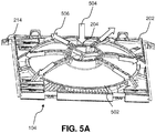
- Fig. 5A illustrates a perspective view of the shroud 104 of the cooling system 200 of Fig. 2A .
- the frame 202 of the shroud 104 can be rectangular frame having an aperture 502 to provide space for receiving the fan socket 204 and rotating blades of the fan.
- the fan socket 204 is of circular shape centrally disposed in the aperture 502 of the frame 202.
- the plurality of arms 210 is of plastic composites, such as for example Polypropylene with 40% Glass Fiber Filler, PA6 composite.
- the plurality of arms 210 may include 2-20 arms, and at least one arm amongst the plurality of arms 210 is bent.
- tension created in the plurality of arms 210 is transmitted along the longitudinal axis 506 of the plurality of arms 210 and distributed within the plurality of arms 210 to minimize the displacement of the fan 206.
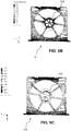
- Figs. 5B and 5C are comparison of displacement of the conventional shroud assembly 12 and the shroud 104 according to the present invention.
- Fig. 5B illustrates a thermal image of displacement of the fan provided in the conventional shroud assembly 12
- Fig. 5C illustrates a thermal image of displacement of the fan 206 provided in the shroud 104 of the present invention.
- 200N Newton
- the cooling system 200 of the present invention efficiently performs even when the vehicle moves in the uneven terrain and avoids damages of any elements in the cooling system 200 during vibration tests of the vehicle.
Landscapes
- Engineering & Computer Science (AREA)
- Chemical & Material Sciences (AREA)
- Combustion & Propulsion (AREA)
- Mechanical Engineering (AREA)
- General Engineering & Computer Science (AREA)
- Cooling, Air Intake And Gas Exhaust, And Fuel Tank Arrangements In Propulsion Units (AREA)
Abstract
A cooling system for a vehicle is provided. The cooling system includes a heat exchanger and a shroud. The shroud is mounted to the heat exchanger at a posterior position with respect to the heat exchanger. The shroud further includes a frame, a fan socket, and a plurality of arms. The frame is provided at a first plane of the shroud to mount the shroud to the heat exchanger. The fan socket is provided at a second plane of the shroud to receive a motor of a fan, where the first plane and the second plane are parallelly spaced apart from each other. The plurality of arms is adapted to be coupled in between the frame and the fan socket to provide rigid support to the fan and minimize displacement of the fan.
Description
- The present invention generally relates to a cooling system, and in particularly, to a shroud assembly to accommodate and support a fan of a cooling system.
- Generally, cooling systems are provided in a vehicle to maintain the temperature of an engine and a passenger cabin of the vehicle at an optimum level. The cooling systems may be a part of Heating Ventilation and Air Conditioning (HVAC) system. Ideally, the cooling systems may include a radiator to exchange heat generated in the engine with the ambient air or the cooling system may include a condenser to reject heat extracted from the vehicle cabin to the ambient air. For example, the radiator is connected with the engine through conduits, the conduits supply heat exchange fluid to the engine to carry away the heat from the engine, the heat exchange fluid getting heated in the process. Further, a fan (e.g., a blower) is provided upstream of the radiator to enable flow of ambient air on the radiator to enable heat exchange between the heat exchange fluid and the ambient air to cool the heat exchange fluid that is heated after extracting heat from the engine. The fan may be provided in a shroud assembly and tightly packed with the radiator core as shown in
Fig. 1 , due to space constraints in the vehicle and to provide optimum ambient air to the radiator.Fig. 1 is a cross-sectional view of aradiator 10 provided with aconventional shroud assembly 12 having afan 14. Theshroud assembly 12 is mounted on theradiator 10 in a posterior position with respect to theradiator 10, and thefan 14 is provided in theshroud assembly 12. Theshroud assembly 12 having arms coupled to a fan socket to provide rigid support to thefan 14. As thefan 14 is tightly mounted on theradiator 10, blades of thefan 14 may collide with theradiator 10 during vibration test of vehicle or when the vehicle is moving on an uneven terrain. Further, collision between the blades of thefan 14 and theradiator 10 may cause considerable damages to the blades of thefan 14 as well as theradiator 10. As the arms of theshroud assembly 12 do not distribute the pressure generated by a load applied on thefan 14, collision between the blades of thefan 14 and theradiator 10 is unavoidable. - Conventionally, the
shroud assembly 12 is made of lighter and cheaper materials to meet market and customer requirements. In order to be cost effective and lighter cooling system, theshroud assembly 12 is made of not so robust materials which may get damaged in high temperature and reduction young's modulus of theshroud assembly 12. However,such shroud assembly 12 tends to bend while during vibration test or any force applied thereon due to use of non-robust material, which leads to damage of the fan and the radiator. - Accordingly, there is a need for a cooling system that provides optimum efficiency and enhanced life span. Further, there is a need for a shroud assembly that withstands high pressure and force applied thereon. Further, there is need for a shroud assembly that is capable of avoiding collision between blades of a fan and radiator.
- In the present description, some elements or parameters may be indexed, such as a first element and a second element. In this case, unless stated otherwise, this indexation is only meant to differentiate and name elements which are similar but not identical. No idea of priority should be inferred from such indexation, as these terms may be switched without betraying the invention. Additionally, this indexation does not imply any order in mounting or use of the elements of the invention.
- In view of the foregoing, an embodiment of the invention herein provides a cooling system for a vehicle. The cooling system includes a heat exchanger and a shroud. The shroud is mounted to the heat exchanger at a posterior position with respect to the heat exchanger. The shroud further includes a frame, a fan socket, and a plurality of arms. The frame is provided at a first plane of the shroud to mount the shroud to the heat exchanger. The fan socket is provided at a second plane of the shroud to receive a motor of a fan, where the first plane and the second plane are parallelly spaced apart from each other. The plurality of arms is adapted to be coupled in between the frame and the fan socket to provide rigid support to the fan and minimize displacement of the fan.
- In one embodiment, the plurality of arms coupled between the frame and the fan socket forms a dome shape to accommodate blades of the fan. In another embodiment, at least one arm of the plurality of arms is bent to form an arc shape. In yet another embodiment, the at least one arm of the plurality of arms is inclined at an angle to form a connection between the fan socket and the frame.
- Generally, the plurality of arms of the shroud is of plastic composites.
- In one embodiment, the plurality of arms is adapted to distribute force, applied on the fan socket in a lateral axis, along a longitudinal axis of the plurality of arms.
- In another embodiment, the fan is provided in between the shroud and the heat exchanger, and heat exchanger is a radiator of the vehicle.
- In yet another embodiment, the frame further includes at least one locking element adapted to engage with at least one complementary groove provided on side walls of the heat exchanger.
- According to another aspect, a shroud assembly for a heat exchanger is provided. The shroud assembly includes a frame, a fan, and a fan socket. The frame is provided at a first plane of the shroud assembly and facilities mounting of the shroud assembly to the heat exchanger, where the frame is at a posterior position with respect to the heat exchanger. The fan having a motor is provided in between the frame and the heat exchanger. The fan socket is provided at a second plane of the shroud assembly to receive the motor of the fan, where the first plane and the second plane are parallelly spaced apart from each other. The plurality of arms is adapted to couple the frame and the fan socket to provide rigid support to the fan and minimize displacement of the fan.
- In one embodiment, the plurality of arms coupled between the frame and the fan socket forms a dome shape to accommodate blades of the fan.
- In another embodiment, the at least one arm of the plurality of arms is bent to form an arc shape.
- In yet another embodiment, the at least one arm of the plurality of arms is inclined at an angle to form an connection between the fan socket and the frame. Further, the shroud assembly is coupled to an upstream side of the heat exchanger
- Other characteristics, details and advantages of the invention can be inferred from the description of the invention hereunder. A more complete appreciation of the invention and many of the attendant advantages thereof will be readily obtained as the same becomes better understood by reference to the following detailed description when considered in connection with the accompanying figures, wherein:
-
Fig. 1 illustrates a schematic view of a conventional shroud assembly, showing an embodiment of a prior art; -
Fig. 2A illustrates a schematic view of a cooling system, in accordance with an embodiment of the present invention; -
Fig. 2B illustrates an exploded view of the cooling system ofFig. 2A ; -
Fig. 3 illustrates a side view of a shroud of the cooling system ofFig. 2A ; -
Fig. 4A illustrates a schematic view of the shroud having a plurality of arms, in accordance to an embodiment of the present invention; -
Fig. 4B illustrates another schematic view of the shroud having the plurality of arms, in accordance to another embodiment of the present invention; -
Fig. 5A illustrates a perspective view of the shroud of the cooling system ofFig. 2A ; -
Fig. 5B illustrates a thermal image of displacement of a fan provided in the conventional shroud assembly ofFig. 1 ; and -
Fig. 5C a thermal image of displacement of a fan provided in the shroud assembly of the present invention. - It must be noted that the figures disclose the invention in a detailed enough way to be implemented, the figures helping to better define the invention if needs be. The invention should however not be limited to the embodiment disclosed in the description.
- The present invention relates to a cooling system for maintaining optimum temperature in a vehicle or for engine cooling. For example, the cooling system can be integrated to a Heating Ventilation and Air-conditioning (HVAC) system to condition air inside a passenger cabin of the vehicle. In another example, the cooling system is adapted to extract heat generated in an engine and reject the same to the environment. The cooling system may include a heat exchanger, preferably a radiator, and a shroud assembly. The cooling system may further include other elements known to the persons skilled in the art. The shroud assembly is mounted on the heat exchanger at a posterior position with respect to the heat exchanger. The shroud assembly may include a frame mounted on the radiator and a fan socket provided in parallel planes spaced apart from each other. Further, the fan socket and the frame are connected by a plurality of arms, which forms a dome shape. As the plurality of arms forms a dome shape, displacement of a fan received in the fan socket towards the radiator is reduced even when the shroud assembly is subjected to any vibration or load. The plurality arms distribute the load or pressure to the frame of the shroud assembly, thereby preventing substantial movement of the fan. Therefore, collision between blades of the fan and the heat exchanger is avoided.
- While aspects relating to a shroud assembly having a plurality of arms to avoid collision between a fan and a heating exchanger as described above and henceforth the plurality of arms can be implemented in any angled shape, the embodiments are described in the context of the following system(s).
-
Figs. 2A and2B illustrate schematic views of acooling system 200 for a vehicle, in accordance with an embodiment of the present invention. In one example,Fig. 2A illustrates a schematic view of thecooling system 200, andFig. 2B illustrates an exploded view of thecooling system 200. Thecooling system 200 may include aheat exchanger 102, and ashroud assembly 104, hereinafter referred to asshroud 104. Further, thecooling system 200 may include other elements (not shown in Figs) required to perform cooling operation, as known to the persons skilled in the art. Theheat exchanger 102 may be a radiator provided at an anterior portion of the vehicle. Theheat exchanger 102 may be connected to an engine or evaporator of a HVAC system through conduits to receive heat exchange fluid. In one example, the heat exchange fluid received from the engine or the evaporator extracts heat generated in the engine or passenger cabin of the vehicle. Theheat exchanger 102 enables heat exchange between the heat exchange fluid and the ambient air flowing thereon. Theshroud 104 can be mounted on theheat exchanger 102 at a posterior position with the respect to theheat exchanger 102. In one embodiment, theshroud 104 can be positioned at an anterior position or the posterior position with respect to theheat exchanger 102 based on the type of fan used in thecooling system 200. For example, if thecooling system 200 is blowing air type, theshroud 104 can be positioned at the anterior position with respect to theheat exchanger 102. Theshroud 104 further includes aframe 202, afan socket 204, and a plurality ofarms 210. Theframe 202 is provided at a first plane of theshroud 104, and thefan socket 204 is provided at a second plane of theshroud 104. The first plane of theframe 202 and second plane of thefan socket 204 will be explained in the forthcoming figures. The first plane and the second plane are parallelly spaced apart from each other. - The
cooling system 200 further includes afan 206, preferably a blower, provided in thefan socket 204 to enable airflow on theheat exchanger 102. In one embodiment, thefan 206 may receive ambient air from the environment and facilitate passing of the air through theheat exchanger 102, in case theshroud 104 is provided in the posterior position with respect to theheat exchanger 102. In another embodiment, thefan 206 may blow the ambient air on theheat exchanger 102, in case theshroud 104 is provided in the anterior position with respect to theheat exchanger 102. Thefan 206 includes amotor 208 provided withblades 212 to enable ambient airflow on theheat exchanger 102. Thefan socket 204 is adapted to receive themotor 208 and theblades 212 of thefan 206 are accommodated adjacent to the plurality ofarms 210. Thefan 206 is provided in thefan socket 204 in such a way that thefan 206 is posterior to theheat exchanger 102 and anterior to theshroud 104. In other words, thefan 206 is provided in between theshroud 104 and theheat exchanger 102. - The plurality of
arms 210 forms a connection between theframe 202 and thefan socket 204 to provide rigid support to thefan 206 and minimize displacement of thefan 206 when any force or load is applied on theshroud 104. As theframe 202 is in the first plane and thefan socket 204 is in the second plane, the plurality ofarms 210 forms an angled connection when connecting the plurality ofarms 210 between theframe 202 and thefan socket 204. As the plurality ofarms 210 is connected between theframe 202 and thefan socket 204 at an angle, the plurality ofarms 210 distributes the force/pressure acting on thefan socket 204 to the edges of theframe 202, thereby minimizing displacement of thefan 206 towards theheat exchanger 102. By minimizing displacement of thefan 206, collision between theblades 212 of thefan 206 and a core of theheat exchanger 102 is avoided, thereby eliminating damages of theblades 212 of thefan 206 and theheat exchanger 102. Theframe 202 further includes one ormore locking elements 214 to mount theshroud 104 on theheat exchanger 102. Theheat exchanger 102 may include one or more complementary grooves provided inside walls 216 of theheat exchanger 102. The one or more complementary grooves receive the one ormore locking elements 214 to enable a connection between theshroud 104 and theheat exchanger 102. -
Fig. 3 illustrates a side view of theshroud 104 of thecooling system 200 ofFig. 2A . As shown inFig. 3 , theframe 202 of theshroud 104 is in thefirst plane 302, and thefan socket 204 is in thesecond plane 304. Thefirst plane 302 is parallelly spaced from thesecond plane 304. In other words, thefirst plane 302 is laterally spaced from thesecond plane 304 of theshroud 104. The plurality ofarms 210 is adapted to connect thefan socket 204 with theframe 202 to distribute the stress/load acting on thefan socket 204 to theframe 202. In one embodiment, at least one arm of the plurality ofarms 210 is bent to form an arc shape. In another embodiment, the plurality ofarms 210 coupled in between theframe 202 and thefan socket 204 forms a dome shape to accommodate theblades 212 of thefan 206. -
Figs 4A and 4B illustrate different views of theshroud 104 of thecooling system 200 ofFig. 1 . In one example,Fig. 4A illustrates a schematic view of theshroud 104 having the plurality ofarms 210, in accordance to an embodiment of the present invention. In this embodiment, the plurality ofarms 210 is formed as dome shaped to accommodate theblades 212 of thefan 206. When any force F acting on thefan socket 204 in alateral axis 402 of thefan socket 204, the plurality ofarms 210 dissipates or distributes the force alonglongitudinal axis 404 of the plurality ofarms 210, the force is ultimately transmitted to theframe 202. According to this embodiment, the plurality ofarms 210 is formed as an arc shape and forms a connection between thefan socket 204 and theframe 202. In another example,Fig. 4B illustrates another schematic view of theshroud 104 having the plurality ofarms 210, in accordance to another embodiment of the present invention. According to the present embodiment, the plurality ofarms 210 is angled arms to form a connection between theframe 202 and thefan socket 204 at an angle "a" marked as 406. The plurality ofarms 210 is inclined at theangle 406 to form a connection between thefan socket 204 and theframe 202. As theframe 202 and thefan socket 204 are in different planes, the plurality ofarms 210 connected between theframe 202 and thefan socket 204 forms an angle with respect to theframe 202. -
Fig. 5A illustrates a perspective view of theshroud 104 of thecooling system 200 ofFig. 2A . Theframe 202 of theshroud 104 can be rectangular frame having anaperture 502 to provide space for receiving thefan socket 204 and rotating blades of the fan. In one embodiment, thefan socket 204 is of circular shape centrally disposed in theaperture 502 of theframe 202. The plurality ofarms 210 is of plastic composites, such as for example Polypropylene with 40% Glass Fiber Filler, PA6 composite. In one embodiment, the plurality ofarms 210 may include 2-20 arms, and at least one arm amongst the plurality ofarms 210 is bent. During vibration or strong shock or impact acting on thefan socket 204 in thelateral direction 504 of thefan socket 204, tension created in the plurality ofarms 210 is transmitted along thelongitudinal axis 506 of the plurality ofarms 210 and distributed within the plurality ofarms 210 to minimize the displacement of thefan 206. -
Figs. 5B and 5C are comparison of displacement of theconventional shroud assembly 12 and theshroud 104 according to the present invention. In one example,Fig. 5B illustrates a thermal image of displacement of the fan provided in theconventional shroud assembly 12, andFig. 5C illustrates a thermal image of displacement of thefan 206 provided in theshroud 104 of the present invention. When the load of 200N (Newton) is applied on both theconventional shroud assembly 12 and theshroud 104 of the present invention, the fan socket of theconventional shroud assembly 12 displaces 5,34mm from its original position as depicted in 508 inFig. 5B , whereas thefan socket 204 of theshroud 104 of the present invention displaces 3,69mm from its original position as depicted in 510 inFig. 5C . Therefore, the plurality ofarms 210 in theshroud 104 of the present invention reduces displacement of thefan socket 204, thereby eliminating collision of thefan 206 with theheat exchanger 102. Further, stiffness of theshroud 104 of the present invention is more than the stiffness of theconventional shroud assembly 12, due to the present design of the plurality ofarms 210. Furthermore, theshroud 104 of the present invention having stiffness of 5420 N/mm when the load 200N applied on theshroud 104, whereas theconventional shroud assembly 12 has 3745 N/mm. Therefore, thecooling system 200 of the present invention efficiently performs even when the vehicle moves in the uneven terrain and avoids damages of any elements in thecooling system 200 during vibration tests of the vehicle. - Obviously, numerous modifications and variations of the present invention are possible in light of the above teachings. It is therefore to be understood that the invention may be practiced otherwise than as specifically described herein.
- In any case, the invention cannot and should not be limited to the embodiments specifically described in this document, as other embodiments might exist. The invention shall spread to any equivalent means and any technically operating combination of means.
Claims (15)
- A cooling system (200) for a vehicle, comprising:a heat exchanger (102); anda shroud (104) mounted to the heat exchanger (102), wherein the shroud (104) further comprising:a frame (202) provided at a first plane (302) of the shroud (104) to mount the shroud (104) to the heat exchanger (102);a fan socket (204) provided at a second plane (304) of the shroud (104) to receive a motor (208) of a fan (206), wherein the first plane (302) and the second plane (304) are parallelly spaced apart from each other; anda plurality of arms (210) adapted to be coupled in between the frame (202) and the fan socket (204) to provide rigid support to the fan (206) and minimize displacement of the fan (206).
- The cooling system (200) as claimed in claim 1, wherein the plurality of arms (210) coupled between the frame (202) and the fan socket (204) forms a dome shape to accommodate blades (212) of the fan (206).
- The cooling system (200) as claimed in claim 1, wherein at least one arm of the plurality of arms (210) is bent to form an arc shape.
- The cooling system (200) as claimed in claim 1, wherein at least one arm of the plurality of arms (210) is inclined at an angle (406) to connect in between the fan socket (204) and the frame (202).
- The cooling system (200) as claimed in any of preceding claims, wherein the plurality of arms (210) of the shroud (104) is of plastic composites.
- The cooling system (200) as claimed in any of preceding claims, wherein the plurality of arms (210) is adapted to distribute force, applied on the fan socket (204) in a lateral axis (402), along a longitudinal axis (404) of the plurality of arms (210).
- The cooling system (200) as claimed in any of preceding claims, wherein the fan (206) is provided in between the shroud (104) and the heat exchanger (102).
- The cooling system (200) as claimed in any of preceding claims, the heat exchanger (102) is a radiator of the vehicle.
- The cooling system (200) as claimed in claim 1, wherein the frame (202) further includes at least one locking element (214) adapted to engage with at least one complementary groove provided in side walls (216) of the heat exchanger (102).
- The cooling system (200) as claimed in any of preceding claims, wherein the shroud (104) is mounted on the heat exchanger (102) at a posterior position with respect to the heat exchanger (102).
- A shroud assembly (104) for a heat exchanger (102), comprising:a frame (202) provided at a first plane (302) of the shroud assembly (104) to mount the shroud assembly (104) to the heat exchanger (102), wherein the frame (202) is at a posterior position with respect to the heat exchanger (102);a fan (206) having a motor (208) provided in between the frame (202) and the heat exchanger (102);a fan socket (204) provided at a second plane (304) of the shroud assembly (104) to receive the motor (208) of the fan (206), wherein the first plane (302) and the second plane (304) are parallelly spaced apart from each other; anda plurality of arms (210) adapted to be coupled in between the frame (202) and the fan socket (204) to provide rigid support to the fan (206) and minimize displacement of the fan (206).
- The shroud assembly (104) as claimed in claim 11, wherein the plurality of arms (210) coupled between the frame (202) and the fan socket (204) forms a dome shape to accommodate blades (212) of the fan (206).
- The shroud assembly (104) as claimed in claim 11, wherein at least one arm of the plurality of arms (210) is bent to form an arc shape.
- The shroud assembly (104) as claimed in claim 11, wherein at least one arm of the plurality of arms (210) is inclined at an angle (406) to connect in between the fan socket (204) and the frame (202).
- The shroud assembly (104) as claimed in claim 11, wherein the shroud assembly (104) is coupled to an upstream side of the heat exchanger (102).
Priority Applications (1)
| Application Number | Priority Date | Filing Date | Title |
|---|---|---|---|
| EP19461540.7A EP3739179A1 (en) | 2019-05-16 | 2019-05-16 | Cooling system with a shroud assembly |
Applications Claiming Priority (1)
| Application Number | Priority Date | Filing Date | Title |
|---|---|---|---|
| EP19461540.7A EP3739179A1 (en) | 2019-05-16 | 2019-05-16 | Cooling system with a shroud assembly |
Publications (1)
| Publication Number | Publication Date |
|---|---|
| EP3739179A1 true EP3739179A1 (en) | 2020-11-18 |
Family
ID=66589495
Family Applications (1)
| Application Number | Title | Priority Date | Filing Date |
|---|---|---|---|
| EP19461540.7A Withdrawn EP3739179A1 (en) | 2019-05-16 | 2019-05-16 | Cooling system with a shroud assembly |
Country Status (1)
| Country | Link |
|---|---|
| EP (1) | EP3739179A1 (en) |
Cited By (1)
| Publication number | Priority date | Publication date | Assignee | Title |
|---|---|---|---|---|
| US20220196281A1 (en) * | 2019-02-27 | 2022-06-23 | Gd Midea Air-Conditioning Equipment Co., Ltd. | Fresh air assembly, air conditioner indoor unit, and air conditioner |
Citations (4)
| Publication number | Priority date | Publication date | Assignee | Title |
|---|---|---|---|---|
| EP0536662A1 (en) * | 1991-10-11 | 1993-04-14 | Siemens Electric Limited | High efficiency, low noise, axial flow fan |
| EP1452820A2 (en) * | 2003-02-21 | 2004-09-01 | Modine Manufacturing Company | Cooling device |
| US20080087025A1 (en) * | 2006-10-12 | 2008-04-17 | Mccain Paul Brian | Evaporator fan with shroud assembly |
| DE202011110551U1 (en) * | 2011-12-27 | 2014-08-12 | Brose Fahrzeugteile GmbH & Co. Kommanditgesellschaft, Würzburg | Radiator frame and radiator assembly |
-
2019
- 2019-05-16 EP EP19461540.7A patent/EP3739179A1/en not_active Withdrawn
Patent Citations (4)
| Publication number | Priority date | Publication date | Assignee | Title |
|---|---|---|---|---|
| EP0536662A1 (en) * | 1991-10-11 | 1993-04-14 | Siemens Electric Limited | High efficiency, low noise, axial flow fan |
| EP1452820A2 (en) * | 2003-02-21 | 2004-09-01 | Modine Manufacturing Company | Cooling device |
| US20080087025A1 (en) * | 2006-10-12 | 2008-04-17 | Mccain Paul Brian | Evaporator fan with shroud assembly |
| DE202011110551U1 (en) * | 2011-12-27 | 2014-08-12 | Brose Fahrzeugteile GmbH & Co. Kommanditgesellschaft, Würzburg | Radiator frame and radiator assembly |
Cited By (2)
| Publication number | Priority date | Publication date | Assignee | Title |
|---|---|---|---|---|
| US20220196281A1 (en) * | 2019-02-27 | 2022-06-23 | Gd Midea Air-Conditioning Equipment Co., Ltd. | Fresh air assembly, air conditioner indoor unit, and air conditioner |
| US12092358B2 (en) * | 2019-02-27 | 2024-09-17 | Gd Midea Air-Conditioning Equipment Co., Ltd. | Fresh air assembly, air conditioner indoor unit, and air conditioner |
Similar Documents
| Publication | Publication Date | Title |
|---|---|---|
| US20050109489A1 (en) | Attachment structure of blower | |
| US7150335B2 (en) | Front end structure of vehicle | |
| US20020014322A1 (en) | Front end structure | |
| JP2002286392A (en) | Vehicle heat exchanger support structure | |
| JP2005096684A (en) | Wind guide structure at the front of the body | |
| US20080061601A1 (en) | Device for Fixing a Heat Transfer Device, In Particular a Coolant Radiator for Motor Vehicles | |
| EP3739179A1 (en) | Cooling system with a shroud assembly | |
| CN205957348U (en) | Heat exchanger fixing plate and air conditioner | |
| JP2019507308A (en) | A device for assembling a heat exchanger of an air conditioner to a radiator for cooling an automobile engine | |
| US7077624B2 (en) | Vehicle cooling fan shroud with an articulatable portion | |
| US20230400040A1 (en) | Fan shroud, mounting bracket, and pin mount | |
| KR101518514B1 (en) | Front end module for protection of cooling module | |
| JP5291401B2 (en) | Fan unit and vehicle cooling system using the same | |
| US11571963B2 (en) | Air guide assembly | |
| EP1167165B1 (en) | Front end structure | |
| KR101902285B1 (en) | Fan and fan shroud having the same | |
| CN102089169B (en) | Ventilation module for vehicle roof-mounted systems | |
| US20200224943A1 (en) | Bracket for a receiver drier | |
| JP2005104212A (en) | Cooling module | |
| KR101528229B1 (en) | Heat exchanger with tube support | |
| CN112689576B (en) | Radiator structure | |
| CN110065384B (en) | Cooling module support structure | |
| KR101528237B1 (en) | Shroud | |
| KR102855868B1 (en) | Air conditioner for Vehicle | |
| KR102002571B1 (en) | Cooling module with dual fan |
Legal Events
| Date | Code | Title | Description |
|---|---|---|---|
| PUAI | Public reference made under article 153(3) epc to a published international application that has entered the european phase |
Free format text: ORIGINAL CODE: 0009012 |
|
| STAA | Information on the status of an ep patent application or granted ep patent |
Free format text: STATUS: THE APPLICATION HAS BEEN PUBLISHED |
|
| AK | Designated contracting states |
Kind code of ref document: A1 Designated state(s): AL AT BE BG CH CY CZ DE DK EE ES FI FR GB GR HR HU IE IS IT LI LT LU LV MC MK MT NL NO PL PT RO RS SE SI SK SM TR |
|
| AX | Request for extension of the european patent |
Extension state: BA ME |
|
| STAA | Information on the status of an ep patent application or granted ep patent |
Free format text: STATUS: THE APPLICATION IS DEEMED TO BE WITHDRAWN |
|
| 18D | Application deemed to be withdrawn |
Effective date: 20210519 |