EP3739178B1 - Exhaust gas treatment device for an internal combustion engine - Google Patents
Exhaust gas treatment device for an internal combustion engine Download PDFInfo
- Publication number
- EP3739178B1 EP3739178B1 EP20174246.7A EP20174246A EP3739178B1 EP 3739178 B1 EP3739178 B1 EP 3739178B1 EP 20174246 A EP20174246 A EP 20174246A EP 3739178 B1 EP3739178 B1 EP 3739178B1
- Authority
- EP
- European Patent Office
- Prior art keywords
- tubular body
- exhaust gas
- treatment device
- gas treatment
- inlet opening
- Prior art date
- Legal status (The legal status is an assumption and is not a legal conclusion. Google has not performed a legal analysis and makes no representation as to the accuracy of the status listed.)
- Revoked
Links
Images





Classifications
-
- F—MECHANICAL ENGINEERING; LIGHTING; HEATING; WEAPONS; BLASTING
- F01—MACHINES OR ENGINES IN GENERAL; ENGINE PLANTS IN GENERAL; STEAM ENGINES
- F01N—GAS-FLOW SILENCERS OR EXHAUST APPARATUS FOR MACHINES OR ENGINES IN GENERAL; GAS-FLOW SILENCERS OR EXHAUST APPARATUS FOR INTERNAL-COMBUSTION ENGINES
- F01N3/00—Exhaust or silencing apparatus having means for purifying, rendering innocuous, or otherwise treating exhaust
- F01N3/08—Exhaust or silencing apparatus having means for purifying, rendering innocuous, or otherwise treating exhaust for rendering innocuous
- F01N3/10—Exhaust or silencing apparatus having means for purifying, rendering innocuous, or otherwise treating exhaust for rendering innocuous by thermal or catalytic conversion of noxious components of exhaust
- F01N3/24—Exhaust or silencing apparatus having means for purifying, rendering innocuous, or otherwise treating exhaust for rendering innocuous by thermal or catalytic conversion of noxious components of exhaust characterised by constructional aspects of converting apparatus
- F01N3/28—Construction of catalytic reactors
-
- F—MECHANICAL ENGINEERING; LIGHTING; HEATING; WEAPONS; BLASTING
- F01—MACHINES OR ENGINES IN GENERAL; ENGINE PLANTS IN GENERAL; STEAM ENGINES
- F01N—GAS-FLOW SILENCERS OR EXHAUST APPARATUS FOR MACHINES OR ENGINES IN GENERAL; GAS-FLOW SILENCERS OR EXHAUST APPARATUS FOR INTERNAL-COMBUSTION ENGINES
- F01N13/00—Exhaust or silencing apparatus characterised by constructional features
- F01N13/009—Exhaust or silencing apparatus characterised by constructional features having two or more separate purifying devices arranged in series
-
- F—MECHANICAL ENGINEERING; LIGHTING; HEATING; WEAPONS; BLASTING
- F01—MACHINES OR ENGINES IN GENERAL; ENGINE PLANTS IN GENERAL; STEAM ENGINES
- F01N—GAS-FLOW SILENCERS OR EXHAUST APPARATUS FOR MACHINES OR ENGINES IN GENERAL; GAS-FLOW SILENCERS OR EXHAUST APPARATUS FOR INTERNAL-COMBUSTION ENGINES
- F01N13/00—Exhaust or silencing apparatus characterised by constructional features
- F01N13/08—Other arrangements or adaptations of exhaust conduits
-
- F—MECHANICAL ENGINEERING; LIGHTING; HEATING; WEAPONS; BLASTING
- F01—MACHINES OR ENGINES IN GENERAL; ENGINE PLANTS IN GENERAL; STEAM ENGINES
- F01N—GAS-FLOW SILENCERS OR EXHAUST APPARATUS FOR MACHINES OR ENGINES IN GENERAL; GAS-FLOW SILENCERS OR EXHAUST APPARATUS FOR INTERNAL-COMBUSTION ENGINES
- F01N13/00—Exhaust or silencing apparatus characterised by constructional features
- F01N13/18—Construction facilitating manufacture, assembly, or disassembly
- F01N13/1838—Construction facilitating manufacture, assembly, or disassembly characterised by the type of connection between parts of exhaust or silencing apparatus, e.g. between housing and tubes, between tubes and baffles
-
- F—MECHANICAL ENGINEERING; LIGHTING; HEATING; WEAPONS; BLASTING
- F01—MACHINES OR ENGINES IN GENERAL; ENGINE PLANTS IN GENERAL; STEAM ENGINES
- F01N—GAS-FLOW SILENCERS OR EXHAUST APPARATUS FOR MACHINES OR ENGINES IN GENERAL; GAS-FLOW SILENCERS OR EXHAUST APPARATUS FOR INTERNAL-COMBUSTION ENGINES
- F01N3/00—Exhaust or silencing apparatus having means for purifying, rendering innocuous, or otherwise treating exhaust
- F01N3/08—Exhaust or silencing apparatus having means for purifying, rendering innocuous, or otherwise treating exhaust for rendering innocuous
-
- F—MECHANICAL ENGINEERING; LIGHTING; HEATING; WEAPONS; BLASTING
- F01—MACHINES OR ENGINES IN GENERAL; ENGINE PLANTS IN GENERAL; STEAM ENGINES
- F01N—GAS-FLOW SILENCERS OR EXHAUST APPARATUS FOR MACHINES OR ENGINES IN GENERAL; GAS-FLOW SILENCERS OR EXHAUST APPARATUS FOR INTERNAL-COMBUSTION ENGINES
- F01N3/00—Exhaust or silencing apparatus having means for purifying, rendering innocuous, or otherwise treating exhaust
- F01N3/08—Exhaust or silencing apparatus having means for purifying, rendering innocuous, or otherwise treating exhaust for rendering innocuous
- F01N3/10—Exhaust or silencing apparatus having means for purifying, rendering innocuous, or otherwise treating exhaust for rendering innocuous by thermal or catalytic conversion of noxious components of exhaust
-
- F—MECHANICAL ENGINEERING; LIGHTING; HEATING; WEAPONS; BLASTING
- F01—MACHINES OR ENGINES IN GENERAL; ENGINE PLANTS IN GENERAL; STEAM ENGINES
- F01N—GAS-FLOW SILENCERS OR EXHAUST APPARATUS FOR MACHINES OR ENGINES IN GENERAL; GAS-FLOW SILENCERS OR EXHAUST APPARATUS FOR INTERNAL-COMBUSTION ENGINES
- F01N3/00—Exhaust or silencing apparatus having means for purifying, rendering innocuous, or otherwise treating exhaust
- F01N3/08—Exhaust or silencing apparatus having means for purifying, rendering innocuous, or otherwise treating exhaust for rendering innocuous
- F01N3/10—Exhaust or silencing apparatus having means for purifying, rendering innocuous, or otherwise treating exhaust for rendering innocuous by thermal or catalytic conversion of noxious components of exhaust
- F01N3/101—Three-way catalysts
-
- F—MECHANICAL ENGINEERING; LIGHTING; HEATING; WEAPONS; BLASTING
- F01—MACHINES OR ENGINES IN GENERAL; ENGINE PLANTS IN GENERAL; STEAM ENGINES
- F01N—GAS-FLOW SILENCERS OR EXHAUST APPARATUS FOR MACHINES OR ENGINES IN GENERAL; GAS-FLOW SILENCERS OR EXHAUST APPARATUS FOR INTERNAL-COMBUSTION ENGINES
- F01N2340/00—Dimensional characteristics of the exhaust system, e.g. length, diameter or volume of the exhaust apparatus; Spatial arrangements of exhaust apparatuses
- F01N2340/02—Distance of the exhaust apparatus to the engine or between two exhaust apparatuses
-
- F—MECHANICAL ENGINEERING; LIGHTING; HEATING; WEAPONS; BLASTING
- F01—MACHINES OR ENGINES IN GENERAL; ENGINE PLANTS IN GENERAL; STEAM ENGINES
- F01N—GAS-FLOW SILENCERS OR EXHAUST APPARATUS FOR MACHINES OR ENGINES IN GENERAL; GAS-FLOW SILENCERS OR EXHAUST APPARATUS FOR INTERNAL-COMBUSTION ENGINES
- F01N2340/00—Dimensional characteristics of the exhaust system, e.g. length, diameter or volume of the exhaust apparatus; Spatial arrangements of exhaust apparatuses
- F01N2340/06—Arrangement of the exhaust apparatus relative to the turbine of a turbocharger
-
- F—MECHANICAL ENGINEERING; LIGHTING; HEATING; WEAPONS; BLASTING
- F01—MACHINES OR ENGINES IN GENERAL; ENGINE PLANTS IN GENERAL; STEAM ENGINES
- F01N—GAS-FLOW SILENCERS OR EXHAUST APPARATUS FOR MACHINES OR ENGINES IN GENERAL; GAS-FLOW SILENCERS OR EXHAUST APPARATUS FOR INTERNAL-COMBUSTION ENGINES
- F01N2470/00—Structure or shape of exhaust gas passages, pipes or tubes
- F01N2470/18—Structure or shape of exhaust gas passages, pipes or tubes the axis of inlet or outlet tubes being other than the longitudinal axis of apparatus
-
- Y—GENERAL TAGGING OF NEW TECHNOLOGICAL DEVELOPMENTS; GENERAL TAGGING OF CROSS-SECTIONAL TECHNOLOGIES SPANNING OVER SEVERAL SECTIONS OF THE IPC; TECHNICAL SUBJECTS COVERED BY FORMER USPC CROSS-REFERENCE ART COLLECTIONS [XRACs] AND DIGESTS
- Y02—TECHNOLOGIES OR APPLICATIONS FOR MITIGATION OR ADAPTATION AGAINST CLIMATE CHANGE
- Y02T—CLIMATE CHANGE MITIGATION TECHNOLOGIES RELATED TO TRANSPORTATION
- Y02T10/00—Road transport of goods or passengers
- Y02T10/10—Internal combustion engine [ICE] based vehicles
- Y02T10/12—Improving ICE efficiencies
Definitions
- This invention relates to an exhaust gas treatment device for an internal combustion engine.
- An internal combustion engine comprises a plurality of cylinders, each of which is connected to an intake manifold via at least one respective intake valve and to an exhaust manifold via at least one respective exhaust valve.
- the intake manifold is connected to a filtering device to receive fresh air (i.e. air from the external environment) and is regulated by a throttle valve, while the exhaust manifold is connected to an exhaust system, which has the function of releasing the gases produced by combustion into the atmosphere, limiting both the noise and the pollutants content.
- the exhaust system comprises at least one exhaust gas treatment device equipped with one or more catalyst monoliths that have the function of transforming unburned hydrocarbons, carbon monoxide (CO) and oxides of nitrogen (NO x ), into carbon dioxide (CO 2 ), water, and nitrogen.
- catalyst monoliths that have the function of transforming unburned hydrocarbons, carbon monoxide (CO) and oxides of nitrogen (NO x ), into carbon dioxide (CO 2 ), water, and nitrogen.
- Patent application DE102016114283A1 describes an exhaust gas post-treatment device
- patent US9689290B2 describes a reducing mixture system for an exhaust gas post-treatment device.
- the purpose of this invention is to provide an exhaust gas treatment device for an internal combustion engine, which makes it possible to minimise the pressure loss (i.e. the drop in pressure to which exhaust gases are subjected when passing through the exhaust gas treatment device) without compromising its ability to reduce pollutants.
- an exhaust gas treatment device for an internal combustion engine is provided, according to what is set forth in the appended claims.
- the reference number 1 indicates, as a whole, an Otto-cycle internal combustion engine (i.e. an engine that runs on petrol or similar fuels).
- the engine 1 comprises four cylinders 2, each of which is connected to an intake manifold 3 via at least one respective intake valve (not illustrated) and to an exhaust manifold 4 via at least one respective exhaust valve (not illustrated).
- the intake manifold 3 receives fresh air (i.e. air from the external environment) through an intake duct 5, which is provided with an air filter 6 and is controlled by a throttle valve 7; the intake manifold 3 is connected to the cylinders 2 via respective intake ducts 8.
- the intake ducts 8 are split as they are provided with a swirl shutter system.
- the exhaust manifold 4 is connected to the cylinders 2 by means of respective exhaust pipes 9; an exhaust system 10 is connected to the exhaust manifold 4, which emits the combustion gases into the atmosphere and comprises an emission duct 11 provided with an exhaust gas treatment device 12; the exhaust gas treatment device 12 comprises a metal catalyst monolith 13, arranged upstream of the flow of exhaust gases, and a ceramic catalyst monolith 14, arranged downstream of the flow of exhaust gases.
- the exhaust system 10 also comprises at least one muffler 15, which shall be connected downstream of the exhaust gas treatment system 12.
- the engine 1 comprises a turbocharger 16, which has the function of compressing the air along the intake duct 5 in order to increase the volumetric efficiency.
- the turbocharger 16 comprises a turbine 17 arranged along the emission duct 11 upstream of the exhaust gas treatment device 12 and a compressor 18 arranged along the intake duct 3 upstream of the throttle valve 7.
- a heat exchanger 19 commonly called “intercooler”
- intercooler which has the function of cooling the intake air to further increase the volumetric efficiency.
- the exhaust gas treatment device 12 comprises a tubular body 20 with a cylindrical shape that extends about a longitudinal symmetry axis A1 (illustrated in Figures 8 and 9 ) and has an inlet opening with a circular shape perpendicular to the longitudinal axis A1 and an outlet opening with a circular shape parallel and opposite the inlet opening and perpendicular to the longitudinal axis A1.
- the exhaust gas treatment device 12 comprises the catalyst monolith 14 that is arranged inside the tubular body 20 and has an inlet surface 21 through which the exhaust gases enter the catalyst monolith 14.
- the catalyst monolith 14 has a cylindrical shape and is coaxial to the tubular body 20, i.e. the longitudinal axis A1 of the tubular body 20 coincides with the longitudinal symmetry axis of the catalyst monolith 14.
- the catalyst monolith 14 is ceramic and is both reducing and oxidizing (i.e. it is a TWC - Three Way Catalyst).
- the exhaust gas treatment device 12 comprises a tubular body 22 that is directly fixed (welded) to the tubular body 20 and has an inlet opening with a circular shape and an outlet opening with a circular shape that is parallel to and faces the inlet opening of the tubular body 20.
- the exhaust gas treatment device 12 comprises the catalyst monolith 13 that is arranged inside the tubular body 22 and has an inlet surface 23 through which the exhaust gases enter the catalyst monolith 13.
- the catalyst monolith 13 has a cylindrical shape and a longitudinal symmetry axis A2 that is not parallel and aligned with the longitudinal axis of the catalyst monolith 14.
- the catalyst monolith 13 is metal and is both reducing and oxidizing (i.e. it is a TWC - Three Way Catalyst).
- the exhaust gas treatment device 12 comprises a tubular body 24 that is hollow on the inside, is directly fixed (welded) to the tubular body 22, and has an inlet opening 25 with a circular shape that can be connected to an outlet of the turbine 17 of the turbocharger 16, and an outlet opening 26 with a circular shape that is parallel to and faces the inlet opening of the tubular body 22.
- the inlet opening of the tubular body 22 is perpendicular to the outlet opening of the tubular body 22.
- the inlet opening 25 of the tubular body 24 forms an obtuse angle ⁇ , with the inlet surface 21 of the catalyst monolith 14, ranging from 105° to 135°, and preferably equal to 115°.
- the inlet opening 25 of the tubular body 24 forms an acute angle ⁇ , with the inlet surface 23 of the catalyst monolith 13, ranging from 17° to 27°, and preferably equal to 22°.
- the catalyst monolith 13 is arranged at a distance not less than 12 mm from the inlet opening of the tubular body 22.
- the longitudinal axis A1 of the catalyst monolith 14 forms an angle ⁇ , with a vertical direction V (perpendicular to a horizontal direction H), ranging from 6° to 10°, and preferably equal to 8°.
- the longitudinal axis A2 of the catalyst monolith 13 forms an angle ⁇ , with the vertical direction V (perpendicular to the horizontal direction H), ranging from 2° to 6°, and preferably equal to 4°, which is opposite the angle ⁇ .
- the tubular body 20 has a circular cross-section; in addition, a side wall 27 of the tubular body consists of a single metal sheet bent onto itself and welded to take on a cylindrical shape.
- the tubular body 22 is obtained by joining two cup-shaped shells 28 and 29 welded to one another: one shell 28 comprises the entire inlet opening and half of the outlet opening, while the other shell 29 comprises the remaining half of the outlet opening (and no part of the inlet opening).
- the outlet opening of the tubular body 22 has a larger diameter than the inlet opening of the tubular body 22.
- the tubular body 22 has a passage area that progressively increases until it reaches a maximum diameter at the outlet opening.
- the inlet opening 25 of the tubular body 24 is not parallel to the outlet opening 26 of the tubular body 24; preferably, the outlet opening 26 of the tubular body 24 is parallel to the inlet surface 23 of the catalyst monolith 13 and, therefore, the inlet opening 25 of the tubular body 24 forms the acute angle ⁇ , with the outlet opening 26 of the tubular body 24, ranging from 17° to 27°, and preferably equal to 22°.
- the tubular body 24 has the shape of a truncated cone that increases in diameter from the inlet opening 25 to the outlet opening 26; consequently, the outlet opening 26 of the tubular body 24 has a larger diameter than the inlet opening 25 of the tubular body 24.
- the exhaust gas treatment device 12 comprises a connecting pipe 30 that receives the exhaust gases from the tubular body 20 and conveys the exhaust gases to the muffler 15.
- the exhaust gas treatment device 12 described above has numerous advantages.
- the exhaust gas treatment device 12 described above makes it possible to minimise the pressure loss i.e. the drop in pressure to which exhaust gases are subjected when they pass through the exhaust gas treatment device 12.
- the exhaust gas treatment device 12 described above has a high pollutant reduction capacity in relation to the actual volume of the two catalyst monoliths 13 and 14.
- the exhaust gas treatment device 12 described above is simple and cost-effective to implement because it requires neither the use of expensive materials nor the use of complex mechanical processing.
Landscapes
- Engineering & Computer Science (AREA)
- Chemical & Material Sciences (AREA)
- Combustion & Propulsion (AREA)
- Mechanical Engineering (AREA)
- General Engineering & Computer Science (AREA)
- Chemical Kinetics & Catalysis (AREA)
- Health & Medical Sciences (AREA)
- Toxicology (AREA)
- Materials Engineering (AREA)
- Exhaust Gas After Treatment (AREA)
- Processes For Solid Components From Exhaust (AREA)
- Cylinder Crankcases Of Internal Combustion Engines (AREA)
Description
- This patent application claims priority from
Italian patent application no. 102019000006960 filed on May 17, 2019 - This invention relates to an exhaust gas treatment device for an internal combustion engine.
- An internal combustion engine comprises a plurality of cylinders, each of which is connected to an intake manifold via at least one respective intake valve and to an exhaust manifold via at least one respective exhaust valve. The intake manifold is connected to a filtering device to receive fresh air (i.e. air from the external environment) and is regulated by a throttle valve, while the exhaust manifold is connected to an exhaust system, which has the function of releasing the gases produced by combustion into the atmosphere, limiting both the noise and the pollutants content.
- The exhaust system comprises at least one exhaust gas treatment device equipped with one or more catalyst monoliths that have the function of transforming unburned hydrocarbons, carbon monoxide (CO) and oxides of nitrogen (NOx), into carbon dioxide (CO2), water, and nitrogen.
- Patent application
DE102016114283A1 describes an exhaust gas post-treatment device, while patentUS9689290B2 - The purpose of this invention is to provide an exhaust gas treatment device for an internal combustion engine, which makes it possible to minimise the pressure loss (i.e. the drop in pressure to which exhaust gases are subjected when passing through the exhaust gas treatment device) without compromising its ability to reduce pollutants.
- According to this invention an exhaust gas treatment device for an internal combustion engine is provided, according to what is set forth in the appended claims.
- The claims describe preferred embodiments of this invention, forming an integral part of this description.
- This invention will now be described with reference to the accompanying drawings, which illustrate a non-limiting embodiment thereof, wherein:
-
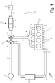
Figure 1 is a perspective view of an internal combustion engine provided with an exhaust gas treatment device made according to this invention; -
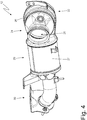
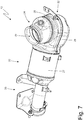
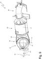
Figures 2-7 are different perspective views of the exhaust gas treatment device inFigure 1 ; -
Figure 8 is a partially longitudinal section view of the exhaust gas treatment device inFigure 1 ; -
Figure 9 is a front view of the exhaust gas treatment device inFigure 1 ; and -
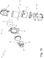
Figure 10 is a perspective, exploded view of the exhaust gas treatment device inFigure 1 . - In
Figure 1 , the reference number 1 indicates, as a whole, an Otto-cycle internal combustion engine (i.e. an engine that runs on petrol or similar fuels). The engine 1 comprises fourcylinders 2, each of which is connected to anintake manifold 3 via at least one respective intake valve (not illustrated) and to anexhaust manifold 4 via at least one respective exhaust valve (not illustrated). - The
intake manifold 3 receives fresh air (i.e. air from the external environment) through anintake duct 5, which is provided with anair filter 6 and is controlled by athrottle valve 7; theintake manifold 3 is connected to thecylinders 2 viarespective intake ducts 8. According to the embodiment illustrated inFigure 1 , theintake ducts 8 are split as they are provided with a swirl shutter system. - Similarly, the
exhaust manifold 4 is connected to thecylinders 2 by means ofrespective exhaust pipes 9; anexhaust system 10 is connected to theexhaust manifold 4, which emits the combustion gases into the atmosphere and comprises anemission duct 11 provided with an exhaustgas treatment device 12; the exhaustgas treatment device 12 comprises ametal catalyst monolith 13, arranged upstream of the flow of exhaust gases, and aceramic catalyst monolith 14, arranged downstream of the flow of exhaust gases. Theexhaust system 10 also comprises at least onemuffler 15, which shall be connected downstream of the exhaustgas treatment system 12. - The engine 1 comprises a
turbocharger 16, which has the function of compressing the air along theintake duct 5 in order to increase the volumetric efficiency. - In particular, the
turbocharger 16 comprises aturbine 17 arranged along theemission duct 11 upstream of the exhaustgas treatment device 12 and acompressor 18 arranged along theintake duct 3 upstream of thethrottle valve 7. Along theintake duct 5 and between thecompressor 18 and theintake manifold 3, there is a heat exchanger 19 (commonly called "intercooler"), which has the function of cooling the intake air to further increase the volumetric efficiency. - As illustrated in
Figures 2-10 , the exhaustgas treatment device 12 comprises atubular body 20 with a cylindrical shape that extends about a longitudinal symmetry axis A1 (illustrated inFigures 8 and9 ) and has an inlet opening with a circular shape perpendicular to the longitudinal axis A1 and an outlet opening with a circular shape parallel and opposite the inlet opening and perpendicular to the longitudinal axis A1. - As illustrated in
Figure 8 , the exhaustgas treatment device 12 comprises thecatalyst monolith 14 that is arranged inside thetubular body 20 and has aninlet surface 21 through which the exhaust gases enter thecatalyst monolith 14. Thecatalyst monolith 14 has a cylindrical shape and is coaxial to thetubular body 20, i.e. the longitudinal axis A1 of thetubular body 20 coincides with the longitudinal symmetry axis of thecatalyst monolith 14. According to a preferred embodiment, thecatalyst monolith 14 is ceramic and is both reducing and oxidizing (i.e. it is a TWC - Three Way Catalyst). - As shown in
Figures 2-10 , the exhaustgas treatment device 12 comprises atubular body 22 that is directly fixed (welded) to thetubular body 20 and has an inlet opening with a circular shape and an outlet opening with a circular shape that is parallel to and faces the inlet opening of thetubular body 20. - As illustrated in
Figure 8 , the exhaustgas treatment device 12 comprises thecatalyst monolith 13 that is arranged inside thetubular body 22 and has aninlet surface 23 through which the exhaust gases enter thecatalyst monolith 13. Thecatalyst monolith 13 has a cylindrical shape and a longitudinal symmetry axis A2 that is not parallel and aligned with the longitudinal axis of thecatalyst monolith 14. According to a preferred embodiment, thecatalyst monolith 13 is metal and is both reducing and oxidizing (i.e. it is a TWC - Three Way Catalyst). - As shown in
Figures 2-10 , the exhaustgas treatment device 12 comprises atubular body 24 that is hollow on the inside, is directly fixed (welded) to thetubular body 22, and has an inlet opening 25 with a circular shape that can be connected to an outlet of theturbine 17 of theturbocharger 16, and an outlet opening 26 with a circular shape that is parallel to and faces the inlet opening of thetubular body 22. - As shown in
Figure 8 , the inlet opening of thetubular body 22 is perpendicular to the outlet opening of thetubular body 22. In addition, the inlet opening 25 of thetubular body 24 forms an obtuse angle α, with theinlet surface 21 of thecatalyst monolith 14, ranging from 105° to 135°, and preferably equal to 115°. - The inlet opening 25 of the
tubular body 24 forms an acute angle β, with theinlet surface 23 of thecatalyst monolith 13, ranging from 17° to 27°, and preferably equal to 22°. Finally, thecatalyst monolith 13 is arranged at a distance not less than 12 mm from the inlet opening of thetubular body 22. - As shown in
Figure 9 , the longitudinal axis A1 of the catalyst monolith 14 (i.e. of the tubular body 20) forms an angle γ, with a vertical direction V (perpendicular to a horizontal direction H), ranging from 6° to 10°, and preferably equal to 8°. In addition, the longitudinal axis A2 of thecatalyst monolith 13 forms an angle δ, with the vertical direction V (perpendicular to the horizontal direction H), ranging from 2° to 6°, and preferably equal to 4°, which is opposite the angle γ. - According to a preferred embodiment illustrated in the attached figures, the
tubular body 20 has a circular cross-section; in addition, aside wall 27 of the tubular body consists of a single metal sheet bent onto itself and welded to take on a cylindrical shape. - According to a preferred embodiment illustrated in the attached figures, the
tubular body 22 is obtained by joining two cup-shaped shells shell 28 comprises the entire inlet opening and half of the outlet opening, while theother shell 29 comprises the remaining half of the outlet opening (and no part of the inlet opening). - According to a preferred embodiment, illustrated in the attached figures, the outlet opening of the
tubular body 22 has a larger diameter than the inlet opening of thetubular body 22. In particular, near the outlet opening thetubular body 22 has a passage area that progressively increases until it reaches a maximum diameter at the outlet opening. - As shown in
Figure 8 , there is an empty volume located inside thetubular body 22 between thecatalyst monolith 13 and the outlet opening. In addition, there is an additional empty volume located inside thetubular body 22, next to thecatalyst monolith 13, and between thecatalyst monolith 13 and a wall of theshell 29 of thetubular body 22 opposite the inlet opening. - As shown in
Figure 8 , the inlet opening 25 of thetubular body 24 is not parallel to the outlet opening 26 of thetubular body 24; preferably, the outlet opening 26 of thetubular body 24 is parallel to theinlet surface 23 of thecatalyst monolith 13 and, therefore, the inlet opening 25 of thetubular body 24 forms the acute angle β, with the outlet opening 26 of thetubular body 24, ranging from 17° to 27°, and preferably equal to 22°. - According to a preferred embodiment illustrated in the attached figures, the
tubular body 24 has the shape of a truncated cone that increases in diameter from the inlet opening 25 to the outlet opening 26; consequently, the outlet opening 26 of thetubular body 24 has a larger diameter than the inlet opening 25 of thetubular body 24. - According to a preferred embodiment illustrated in the attached figures, the exhaust
gas treatment device 12 comprises a connectingpipe 30 that receives the exhaust gases from thetubular body 20 and conveys the exhaust gases to themuffler 15. - The embodiments described herein may be combined with each other
- The exhaust
gas treatment device 12 described above has numerous advantages. - First, the exhaust
gas treatment device 12 described above makes it possible to minimise the pressure loss i.e. the drop in pressure to which exhaust gases are subjected when they pass through the exhaustgas treatment device 12. - In addition, the exhaust
gas treatment device 12 described above has a high pollutant reduction capacity in relation to the actual volume of the twocatalyst monoliths - Finally, the exhaust
gas treatment device 12 described above is simple and cost-effective to implement because it requires neither the use of expensive materials nor the use of complex mechanical processing. -
- 1
- engine
- 2
- cylinders
- 3
- intake manifold
- 4
- exhaust manifold
- 5
- intake duct
- 6
- air filter
- 7
- throttle valve
- 8
- intake ducts
- 9
- exhaust pipes
- 10
- exhaust system
- 11
- emission duct
- 12
- treatment device
- 13
- catalyst monolith
- 14
- catalyst monolith
- 15
- muffler
- 16
- turbocharger
- 17
- turbine
- 18
- compressor
- 19
- heat exchanger
- 20
- tubular body
- 21
- inlet surface
- 22
- tubular body
- 23
- inlet surface
- 24
- tubular body
- 25
- inlet opening
- 26
- outlet opening
- 27
- side wall
- 28
- shell
- 29
- shell
- 30
- connection pipe
Claims (12)
- An exhaust gas treatment device (12) for an internal combustion engine (1); the exhaust gas treatment device (12) comprises:a first tubular body (20) with a cylindrical shape, which develops around a longitudinal symmetry axis (A1) and has a first inlet opening with a circular shape, which is perpendicular to the longitudinal axis (A1), and a first outlet opening with a circular shape, which is parallel to and opposite the first inlet opening and perpendicular to the longitudinal axis (A1);a first catalyst monolith (14), which is arranged inside the first tubular body (20) and has a first inlet surface (21), through which the exhaust gases get into the first catalyst monolith (14);a second tubular body (22), which is directly fixed to the first tubular body (20) and has a second inlet opening with a circular shape and a second outlet opening with a circular shape, which is parallel to and faces the first inlet opening of the first tubular body (20);a second catalyst monolith (13), which is arranged inside the second tubular body (22) and has a second inlet surface (23), through which the exhaust gases get into the second catalyst monolith (13);a third tubular body (24), which is hollow on the inside, is directly fixed to the second tubular body (22) and has a third inlet opening (25) with a circular shape, which can be connected to an outlet of a turbine (17) of a turbocharger (16) of the internal combustion engine (1), and a third outlet opening (26) with a circular shape, which is parallel to and faces the second inlet opening of the second tubular body (22); andthe second inlet opening of the second tubular body (22) is perpendicular to the second outlet opening of the second tubular body (22);the exhaust gas treatment device (12) is characterized in that:the third inlet opening (25) of the third tubular body (24) forms, with the first inlet surface (21) of the first catalyst monolith (14), a first obtuse angle (α) ranging from 105° to 135° and preferably equal to 115°; andthe third inlet opening (25) of the third tubular body (24) forms, with the second inlet surface (23) of the second catalyst monolith (13), a second acute angle (β) ranging from 17° to 27° and preferably equal to 22°.
- The exhaust gas treatment device (12) according to claim 1, wherein the first tubular body (20) has a circular cross section.
- The exhaust gas treatment device (12) according to claim 1 or 2, wherein a side wall (27) of the first tubular body (20) consists of one single metal sheet bent onto itself in order to assume a cylindrical shape.
- The exhaust gas treatment device (12) according to claim 1, 2 or 3, wherein:the second tubular body (22) is obtained by joining two cup-shaped shells (28, 29) welded to one another;a first shell (28) comprises the entire second inlet opening and half of the second outlet opening; anda second shell (29) comprises a remaining half of the second outlet opening.
- The exhaust gas treatment device (12) according to one of the claims from 1 to 4, wherein the second outlet opening of the second tubular body (22) has a greater diameter than the second inlet opening of the second tubular body (22).
- The exhaust gas treatment device (12) according to one of the claims from 1 to 5, wherein the third outlet opening (26) of the third tubular body (24) has a greater diameter than the third inlet opening (25) of the third tubular body (24).
- The exhaust gas treatment device (12) according to claim 6, wherein the third tubular body (24) has the shape of a truncated cone, which increases the diameter from the third inlet opening (25) to the third outlet opening (26).
- The exhaust gas treatment device (12) according to one of the claims from 1 to 7, wherein the third inlet opening (25) of the third tubular body (24) is not parallel to the third outlet opening (26) of the third tubular body (24) .
- The exhaust gas treatment device (12) according to one of the claims from 1 to 8, wherein the second catalyst monolith (13) is arranged at a distance no less than 12 mm from the second inlet opening of the second tubular body (22) .
- The exhaust gas treatment device (12) according to one of the claims from 1 to 9, wherein, close to the second outlet opening, the second tubular body (22) has a passage area, which progressively increases until reaching a maximum value at the second outlet opening.
- The exhaust gas treatment device (12) according to one of the claims from 1 to 10, wherein there is a first empty volume, which is located inside the second tubular body (22) between the second catalyst monolith (13) and the second outlet opening.
- The exhaust gas treatment device (12) according to one of the claims from 1 to 11, wherein there is a second empty volume, which is located inside the second tubular body (22), next to the second catalyst monolith (13), between the second catalyst monolith (13) and a wall of the second tubular body (22), which is opposite the second outlet opening.
Applications Claiming Priority (1)
| Application Number | Priority Date | Filing Date | Title |
|---|---|---|---|
| IT102019000006960A IT201900006960A1 (en) | 2019-05-17 | 2019-05-17 | EXHAUST GAS TREATMENT DEVICE FOR AN INTERNAL COMBUSTION ENGINE |
Publications (2)
| Publication Number | Publication Date |
|---|---|
| EP3739178A1 EP3739178A1 (en) | 2020-11-18 |
| EP3739178B1 true EP3739178B1 (en) | 2021-12-29 |
Family
ID=67809581
Family Applications (1)
| Application Number | Title | Priority Date | Filing Date |
|---|---|---|---|
| EP20174246.7A Revoked EP3739178B1 (en) | 2019-05-17 | 2020-05-12 | Exhaust gas treatment device for an internal combustion engine |
Country Status (4)
| Country | Link |
|---|---|
| EP (1) | EP3739178B1 (en) |
| CN (1) | CN111946430A (en) |
| BR (1) | BR102020009756A2 (en) |
| IT (1) | IT201900006960A1 (en) |
Citations (3)
| Publication number | Priority date | Publication date | Assignee | Title |
|---|---|---|---|---|
| EP2440759B1 (en) | 2009-06-12 | 2014-07-30 | Emitec Gesellschaft für Emissionstechnologie mbH | Exhaust gas treatment device for use near an engine |
| US9689290B2 (en) | 2015-12-01 | 2017-06-27 | GM Global Technology Operations LLC | Reductant mixing system for an exhaust gas after-treatment device |
| DE102016114283A1 (en) | 2016-08-02 | 2018-02-08 | Benteler Automobiltechnik Gmbh | exhaust aftertreatment arrangement |
Family Cites Families (4)
| Publication number | Priority date | Publication date | Assignee | Title |
|---|---|---|---|---|
| EP0809001B1 (en) * | 1996-05-23 | 2003-01-22 | Scambia Industrial Developments Aktiengesellschaft | Exhaust manifold with catalyst |
| DE112005001774A5 (en) * | 2004-08-09 | 2008-06-26 | Avl List Gmbh | Internal combustion engine |
| DE102012021017B4 (en) * | 2012-10-26 | 2026-03-19 | Mercedes-Benz Group AG | Exhaust system |
| US10215075B2 (en) * | 2014-10-24 | 2019-02-26 | Faurecia Emissions Control Technologies, Usa, Llc | Modular mixer inlet and mixer assembly to provide for compact mixer |
-
2019
- 2019-05-17 IT IT102019000006960A patent/IT201900006960A1/en unknown
-
2020
- 2020-05-12 EP EP20174246.7A patent/EP3739178B1/en not_active Revoked
- 2020-05-15 BR BR102020009756-3A patent/BR102020009756A2/en not_active Application Discontinuation
- 2020-05-18 CN CN202010420473.2A patent/CN111946430A/en active Pending
Patent Citations (3)
| Publication number | Priority date | Publication date | Assignee | Title |
|---|---|---|---|---|
| EP2440759B1 (en) | 2009-06-12 | 2014-07-30 | Emitec Gesellschaft für Emissionstechnologie mbH | Exhaust gas treatment device for use near an engine |
| US9689290B2 (en) | 2015-12-01 | 2017-06-27 | GM Global Technology Operations LLC | Reductant mixing system for an exhaust gas after-treatment device |
| DE102016114283A1 (en) | 2016-08-02 | 2018-02-08 | Benteler Automobiltechnik Gmbh | exhaust aftertreatment arrangement |
Also Published As
| Publication number | Publication date |
|---|---|
| CN111946430A (en) | 2020-11-17 |
| EP3739178A1 (en) | 2020-11-18 |
| BR102020009756A2 (en) | 2021-07-06 |
| IT201900006960A1 (en) | 2020-11-17 |
Similar Documents
| Publication | Publication Date | Title |
|---|---|---|
| US7568340B2 (en) | Exhaust gas recirculation mixer | |
| US7757484B2 (en) | Exhaust treatment device having flow-promoting end caps | |
| CA2015884C (en) | Emission control apparatus | |
| CN101225778B (en) | An exhaust system for an internal combustion engine provided with an exhaust gas recirculation circuit | |
| US10247079B2 (en) | Exhaust gas purification system of internal combustion engine having turbocharger | |
| KR101853601B1 (en) | Noise reduction structure and supercharging device | |
| WO2022240596A1 (en) | Surface component for vehicle exhaust system | |
| EP2322787B1 (en) | Exhaust gas recirculation system | |
| CN1844647A (en) | muffler with catalytic converter | |
| EP3739178A1 (en) | Exhaust gas treatment device for an internal combustion engine | |
| US4149378A (en) | Exhaust system affecting suction of secondary air by use of larger connector pipe | |
| US20090007551A1 (en) | Exhaust Gas Aftertreatment System | |
| EP2236804A1 (en) | Gas mixing device particularly for internal-combustion engines equipped with exhaust gas recirculation system | |
| CN112431650B (en) | A crankcase forced ventilation system, supercharged engine, automobile | |
| US11391195B2 (en) | Exhaust system and muffler | |
| US5392601A (en) | Exhaust system for an internal combustion engine | |
| US10738655B2 (en) | Turbine outlet flow control device | |
| CA3111419A1 (en) | Internal combustion engine exhaust mufflers, systems, cutout systems, and related methods | |
| US11692470B2 (en) | Exhaust system and muffler | |
| EP1452704B1 (en) | Exhaust gas device and system having reduced flow restriction | |
| KR20240037021A (en) | Fuel efficiency improvement, soot purifier and driving performance improve device of internal combustion engine | |
| JP2008163917A (en) | Exhaust emission control device | |
| EP1473504A1 (en) | Exhaust manifold for an engine |
Legal Events
| Date | Code | Title | Description |
|---|---|---|---|
| PUAI | Public reference made under article 153(3) epc to a published international application that has entered the european phase |
Free format text: ORIGINAL CODE: 0009012 |
|
| STAA | Information on the status of an ep patent application or granted ep patent |
Free format text: STATUS: THE APPLICATION HAS BEEN PUBLISHED |
|
| AK | Designated contracting states |
Kind code of ref document: A1 Designated state(s): AL AT BE BG CH CY CZ DE DK EE ES FI FR GB GR HR HU IE IS IT LI LT LU LV MC MK MT NL NO PL PT RO RS SE SI SK SM TR |
|
| AX | Request for extension of the european patent |
Extension state: BA ME |
|
| STAA | Information on the status of an ep patent application or granted ep patent |
Free format text: STATUS: REQUEST FOR EXAMINATION WAS MADE |
|
| 17P | Request for examination filed |
Effective date: 20210510 |
|
| GRAP | Despatch of communication of intention to grant a patent |
Free format text: ORIGINAL CODE: EPIDOSNIGR1 |
|
| STAA | Information on the status of an ep patent application or granted ep patent |
Free format text: STATUS: GRANT OF PATENT IS INTENDED |
|
| INTG | Intention to grant announced |
Effective date: 20210721 |
|
| GRAS | Grant fee paid |
Free format text: ORIGINAL CODE: EPIDOSNIGR3 |
|
| GRAA | (expected) grant |
Free format text: ORIGINAL CODE: 0009210 |
|
| STAA | Information on the status of an ep patent application or granted ep patent |
Free format text: STATUS: THE PATENT HAS BEEN GRANTED |
|
| AK | Designated contracting states |
Kind code of ref document: B1 Designated state(s): AL AT BE BG CH CY CZ DE DK EE ES FI FR GB GR HR HU IE IS IT LI LT LU LV MC MK MT NL NO PL PT RO RS SE SI SK SM TR |
|
| REG | Reference to a national code |
Ref country code: GB Ref legal event code: FG4D |
|
| REG | Reference to a national code |
Ref country code: CH Ref legal event code: EP |
|
| REG | Reference to a national code |
Ref country code: AT Ref legal event code: REF Ref document number: 1458841 Country of ref document: AT Kind code of ref document: T Effective date: 20220115 |
|
| REG | Reference to a national code |
Ref country code: IE Ref legal event code: FG4D |
|
| REG | Reference to a national code |
Ref country code: DE Ref legal event code: R096 Ref document number: 602020001434 Country of ref document: DE |
|
| REG | Reference to a national code |
Ref country code: LT Ref legal event code: MG9D |
|
| PG25 | Lapsed in a contracting state [announced via postgrant information from national office to epo] |
Ref country code: RS Free format text: LAPSE BECAUSE OF FAILURE TO SUBMIT A TRANSLATION OF THE DESCRIPTION OR TO PAY THE FEE WITHIN THE PRESCRIBED TIME-LIMIT Effective date: 20211229 Ref country code: LT Free format text: LAPSE BECAUSE OF FAILURE TO SUBMIT A TRANSLATION OF THE DESCRIPTION OR TO PAY THE FEE WITHIN THE PRESCRIBED TIME-LIMIT Effective date: 20211229 Ref country code: FI Free format text: LAPSE BECAUSE OF FAILURE TO SUBMIT A TRANSLATION OF THE DESCRIPTION OR TO PAY THE FEE WITHIN THE PRESCRIBED TIME-LIMIT Effective date: 20211229 Ref country code: BG Free format text: LAPSE BECAUSE OF FAILURE TO SUBMIT A TRANSLATION OF THE DESCRIPTION OR TO PAY THE FEE WITHIN THE PRESCRIBED TIME-LIMIT Effective date: 20220329 |
|
| REG | Reference to a national code |
Ref country code: NL Ref legal event code: MP Effective date: 20211229 |
|
| REG | Reference to a national code |
Ref country code: AT Ref legal event code: MK05 Ref document number: 1458841 Country of ref document: AT Kind code of ref document: T Effective date: 20211229 |
|
| PG25 | Lapsed in a contracting state [announced via postgrant information from national office to epo] |
Ref country code: SE Free format text: LAPSE BECAUSE OF FAILURE TO SUBMIT A TRANSLATION OF THE DESCRIPTION OR TO PAY THE FEE WITHIN THE PRESCRIBED TIME-LIMIT Effective date: 20211229 Ref country code: NO Free format text: LAPSE BECAUSE OF FAILURE TO SUBMIT A TRANSLATION OF THE DESCRIPTION OR TO PAY THE FEE WITHIN THE PRESCRIBED TIME-LIMIT Effective date: 20220329 Ref country code: LV Free format text: LAPSE BECAUSE OF FAILURE TO SUBMIT A TRANSLATION OF THE DESCRIPTION OR TO PAY THE FEE WITHIN THE PRESCRIBED TIME-LIMIT Effective date: 20211229 Ref country code: HR Free format text: LAPSE BECAUSE OF FAILURE TO SUBMIT A TRANSLATION OF THE DESCRIPTION OR TO PAY THE FEE WITHIN THE PRESCRIBED TIME-LIMIT Effective date: 20211229 Ref country code: GR Free format text: LAPSE BECAUSE OF FAILURE TO SUBMIT A TRANSLATION OF THE DESCRIPTION OR TO PAY THE FEE WITHIN THE PRESCRIBED TIME-LIMIT Effective date: 20220330 |
|
| PG25 | Lapsed in a contracting state [announced via postgrant information from national office to epo] |
Ref country code: NL Free format text: LAPSE BECAUSE OF FAILURE TO SUBMIT A TRANSLATION OF THE DESCRIPTION OR TO PAY THE FEE WITHIN THE PRESCRIBED TIME-LIMIT Effective date: 20211229 |
|
| PG25 | Lapsed in a contracting state [announced via postgrant information from national office to epo] |
Ref country code: SM Free format text: LAPSE BECAUSE OF FAILURE TO SUBMIT A TRANSLATION OF THE DESCRIPTION OR TO PAY THE FEE WITHIN THE PRESCRIBED TIME-LIMIT Effective date: 20211229 Ref country code: SK Free format text: LAPSE BECAUSE OF FAILURE TO SUBMIT A TRANSLATION OF THE DESCRIPTION OR TO PAY THE FEE WITHIN THE PRESCRIBED TIME-LIMIT Effective date: 20211229 Ref country code: RO Free format text: LAPSE BECAUSE OF FAILURE TO SUBMIT A TRANSLATION OF THE DESCRIPTION OR TO PAY THE FEE WITHIN THE PRESCRIBED TIME-LIMIT Effective date: 20211229 Ref country code: PT Free format text: LAPSE BECAUSE OF FAILURE TO SUBMIT A TRANSLATION OF THE DESCRIPTION OR TO PAY THE FEE WITHIN THE PRESCRIBED TIME-LIMIT Effective date: 20220429 Ref country code: ES Free format text: LAPSE BECAUSE OF FAILURE TO SUBMIT A TRANSLATION OF THE DESCRIPTION OR TO PAY THE FEE WITHIN THE PRESCRIBED TIME-LIMIT Effective date: 20211229 Ref country code: EE Free format text: LAPSE BECAUSE OF FAILURE TO SUBMIT A TRANSLATION OF THE DESCRIPTION OR TO PAY THE FEE WITHIN THE PRESCRIBED TIME-LIMIT Effective date: 20211229 Ref country code: CZ Free format text: LAPSE BECAUSE OF FAILURE TO SUBMIT A TRANSLATION OF THE DESCRIPTION OR TO PAY THE FEE WITHIN THE PRESCRIBED TIME-LIMIT Effective date: 20211229 |
|
| PG25 | Lapsed in a contracting state [announced via postgrant information from national office to epo] |
Ref country code: PL Free format text: LAPSE BECAUSE OF FAILURE TO SUBMIT A TRANSLATION OF THE DESCRIPTION OR TO PAY THE FEE WITHIN THE PRESCRIBED TIME-LIMIT Effective date: 20211229 Ref country code: AT Free format text: LAPSE BECAUSE OF FAILURE TO SUBMIT A TRANSLATION OF THE DESCRIPTION OR TO PAY THE FEE WITHIN THE PRESCRIBED TIME-LIMIT Effective date: 20211229 |
|
| REG | Reference to a national code |
Ref country code: DE Ref legal event code: R026 Ref document number: 602020001434 Country of ref document: DE |
|
| PG25 | Lapsed in a contracting state [announced via postgrant information from national office to epo] |
Ref country code: IS Free format text: LAPSE BECAUSE OF FAILURE TO SUBMIT A TRANSLATION OF THE DESCRIPTION OR TO PAY THE FEE WITHIN THE PRESCRIBED TIME-LIMIT Effective date: 20220429 |
|
| PLBI | Opposition filed |
Free format text: ORIGINAL CODE: 0009260 |
|
| PLAX | Notice of opposition and request to file observation + time limit sent |
Free format text: ORIGINAL CODE: EPIDOSNOBS2 |
|
| PG25 | Lapsed in a contracting state [announced via postgrant information from national office to epo] |
Ref country code: DK Free format text: LAPSE BECAUSE OF FAILURE TO SUBMIT A TRANSLATION OF THE DESCRIPTION OR TO PAY THE FEE WITHIN THE PRESCRIBED TIME-LIMIT Effective date: 20211229 Ref country code: AL Free format text: LAPSE BECAUSE OF FAILURE TO SUBMIT A TRANSLATION OF THE DESCRIPTION OR TO PAY THE FEE WITHIN THE PRESCRIBED TIME-LIMIT Effective date: 20211229 |
|
| 26 | Opposition filed |
Opponent name: PUREM GMBH Effective date: 20220923 |
|
| PLBP | Opposition withdrawn |
Free format text: ORIGINAL CODE: 0009264 |
|
| REG | Reference to a national code |
Ref country code: BE Ref legal event code: MM Effective date: 20220531 |
|
| PG25 | Lapsed in a contracting state [announced via postgrant information from national office to epo] |
Ref country code: MC Free format text: LAPSE BECAUSE OF FAILURE TO SUBMIT A TRANSLATION OF THE DESCRIPTION OR TO PAY THE FEE WITHIN THE PRESCRIBED TIME-LIMIT Effective date: 20211229 Ref country code: LU Free format text: LAPSE BECAUSE OF NON-PAYMENT OF DUE FEES Effective date: 20220512 |
|
| PG25 | Lapsed in a contracting state [announced via postgrant information from national office to epo] |
Ref country code: SI Free format text: LAPSE BECAUSE OF FAILURE TO SUBMIT A TRANSLATION OF THE DESCRIPTION OR TO PAY THE FEE WITHIN THE PRESCRIBED TIME-LIMIT Effective date: 20211229 |
|
| PLBB | Reply of patent proprietor to notice(s) of opposition received |
Free format text: ORIGINAL CODE: EPIDOSNOBS3 |
|
| PG25 | Lapsed in a contracting state [announced via postgrant information from national office to epo] |
Ref country code: IE Free format text: LAPSE BECAUSE OF NON-PAYMENT OF DUE FEES Effective date: 20220512 |
|
| PG25 | Lapsed in a contracting state [announced via postgrant information from national office to epo] |
Ref country code: IT Free format text: LAPSE BECAUSE OF FAILURE TO SUBMIT A TRANSLATION OF THE DESCRIPTION OR TO PAY THE FEE WITHIN THE PRESCRIBED TIME-LIMIT Effective date: 20211229 Ref country code: BE Free format text: LAPSE BECAUSE OF NON-PAYMENT OF DUE FEES Effective date: 20220531 |
|
| PGFP | Annual fee paid to national office [announced via postgrant information from national office to epo] |
Ref country code: FR Payment date: 20230420 Year of fee payment: 4 Ref country code: DE Payment date: 20230419 Year of fee payment: 4 |
|
| REG | Reference to a national code |
Ref country code: CH Ref legal event code: PL |
|
| PG25 | Lapsed in a contracting state [announced via postgrant information from national office to epo] |
Ref country code: LI Free format text: LAPSE BECAUSE OF NON-PAYMENT OF DUE FEES Effective date: 20230531 Ref country code: CH Free format text: LAPSE BECAUSE OF NON-PAYMENT OF DUE FEES Effective date: 20230531 |
|
| RDAF | Communication despatched that patent is revoked |
Free format text: ORIGINAL CODE: EPIDOSNREV1 |
|
| REG | Reference to a national code |
Ref country code: DE Ref legal event code: R103 Ref document number: 602020001434 Country of ref document: DE Ref country code: DE Ref legal event code: R064 Ref document number: 602020001434 Country of ref document: DE |
|
| PG25 | Lapsed in a contracting state [announced via postgrant information from national office to epo] |
Ref country code: MK Free format text: LAPSE BECAUSE OF FAILURE TO SUBMIT A TRANSLATION OF THE DESCRIPTION OR TO PAY THE FEE WITHIN THE PRESCRIBED TIME-LIMIT Effective date: 20211229 Ref country code: CY Free format text: LAPSE BECAUSE OF FAILURE TO SUBMIT A TRANSLATION OF THE DESCRIPTION OR TO PAY THE FEE WITHIN THE PRESCRIBED TIME-LIMIT Effective date: 20211229 |
|
| PG25 | Lapsed in a contracting state [announced via postgrant information from national office to epo] |
Ref country code: HU Free format text: LAPSE BECAUSE OF FAILURE TO SUBMIT A TRANSLATION OF THE DESCRIPTION OR TO PAY THE FEE WITHIN THE PRESCRIBED TIME-LIMIT; INVALID AB INITIO Effective date: 20200512 |
|
| PG25 | Lapsed in a contracting state [announced via postgrant information from national office to epo] |
Ref country code: TR Free format text: LAPSE BECAUSE OF FAILURE TO SUBMIT A TRANSLATION OF THE DESCRIPTION OR TO PAY THE FEE WITHIN THE PRESCRIBED TIME-LIMIT Effective date: 20211229 |
|
| RDAG | Patent revoked |
Free format text: ORIGINAL CODE: 0009271 |
|
| STAA | Information on the status of an ep patent application or granted ep patent |
Free format text: STATUS: PATENT REVOKED |
|
| REG | Reference to a national code |
Ref country code: CH Ref legal event code: PL |
|
| 27W | Patent revoked |
Effective date: 20240402 |
|
| GBPR | Gb: patent revoked under art. 102 of the ep convention designating the uk as contracting state |
Effective date: 20240402 |