EP3739151A1 - Locking mechanism for sliding doors and windows - Google Patents
Locking mechanism for sliding doors and windows Download PDFInfo
- Publication number
- EP3739151A1 EP3739151A1 EP19398006.7A EP19398006A EP3739151A1 EP 3739151 A1 EP3739151 A1 EP 3739151A1 EP 19398006 A EP19398006 A EP 19398006A EP 3739151 A1 EP3739151 A1 EP 3739151A1
- Authority
- EP
- European Patent Office
- Prior art keywords
- locking mechanism
- chamber
- toggle
- blocking
- lock
- Prior art date
- Legal status (The legal status is an assumption and is not a legal conclusion. Google has not performed a legal analysis and makes no representation as to the accuracy of the status listed.)
- Granted
Links
Images





Classifications
-
- E—FIXED CONSTRUCTIONS
- E05—LOCKS; KEYS; WINDOW OR DOOR FITTINGS; SAFES
- E05B—LOCKS; ACCESSORIES THEREFOR; HANDCUFFS
- E05B65/00—Locks or fastenings for special use
- E05B65/0028—Locks or fastenings for special use for narrow-stile wings
-
- E—FIXED CONSTRUCTIONS
- E05—LOCKS; KEYS; WINDOW OR DOOR FITTINGS; SAFES
- E05B—LOCKS; ACCESSORIES THEREFOR; HANDCUFFS
- E05B65/00—Locks or fastenings for special use
- E05B65/08—Locks or fastenings for special use for sliding wings
-
- E—FIXED CONSTRUCTIONS
- E05—LOCKS; KEYS; WINDOW OR DOOR FITTINGS; SAFES
- E05B—LOCKS; ACCESSORIES THEREFOR; HANDCUFFS
- E05B1/00—Knobs or handles for wings; Knobs, handles, or press buttons for locks or latches on wings
- E05B1/0038—Sliding handles, e.g. push buttons
- E05B1/0046—Sliding handles, e.g. push buttons sliding parallel to the plane of the wing
-
- E—FIXED CONSTRUCTIONS
- E05—LOCKS; KEYS; WINDOW OR DOOR FITTINGS; SAFES
- E05B—LOCKS; ACCESSORIES THEREFOR; HANDCUFFS
- E05B13/00—Devices preventing the key or the handle or both from being used
- E05B13/10—Devices preventing the key or the handle or both from being used formed by a lock arranged in the handle
-
- E—FIXED CONSTRUCTIONS
- E05—LOCKS; KEYS; WINDOW OR DOOR FITTINGS; SAFES
- E05B—LOCKS; ACCESSORIES THEREFOR; HANDCUFFS
- E05B15/00—Other details of locks; Parts for engagement by bolts of fastening devices
- E05B15/08—Key guides; Key pins ; Keyholes; Keyhole finders
-
- E—FIXED CONSTRUCTIONS
- E05—LOCKS; KEYS; WINDOW OR DOOR FITTINGS; SAFES
- E05Y—INDEXING SCHEME ASSOCIATED WITH SUBCLASSES E05D AND E05F, RELATING TO CONSTRUCTION ELEMENTS, ELECTRIC CONTROL, POWER SUPPLY, POWER SIGNAL OR TRANSMISSION, USER INTERFACES, MOUNTING OR COUPLING, DETAILS, ACCESSORIES, AUXILIARY OPERATIONS NOT OTHERWISE PROVIDED FOR, APPLICATION THEREOF
- E05Y2900/00—Application of doors, windows, wings or fittings thereof
- E05Y2900/10—Application of doors, windows, wings or fittings thereof for buildings or parts thereof
- E05Y2900/13—Type of wing
- E05Y2900/132—Doors
-
- E—FIXED CONSTRUCTIONS
- E05—LOCKS; KEYS; WINDOW OR DOOR FITTINGS; SAFES
- E05Y—INDEXING SCHEME ASSOCIATED WITH SUBCLASSES E05D AND E05F, RELATING TO CONSTRUCTION ELEMENTS, ELECTRIC CONTROL, POWER SUPPLY, POWER SIGNAL OR TRANSMISSION, USER INTERFACES, MOUNTING OR COUPLING, DETAILS, ACCESSORIES, AUXILIARY OPERATIONS NOT OTHERWISE PROVIDED FOR, APPLICATION THEREOF
- E05Y2900/00—Application of doors, windows, wings or fittings thereof
- E05Y2900/10—Application of doors, windows, wings or fittings thereof for buildings or parts thereof
- E05Y2900/13—Type of wing
- E05Y2900/148—Windows
Definitions
- the present invention relates to locking mechanisms for sliding doors and windows.
- the locking mechanisms whose construction involves difficult blocking and unblocking processes cause a decrease in the operation capability of the sliding doors and windows there-between.
- the purpose of the present invention is to provide a locking mechanism for sliding doors and windows which allows to overcome the disadvantages and problems of the prior art and which meets the needs of an agile working of the frame structures.
- An object of the present invention is to provide a locking mechanism for sliding doors and windows which presents dimensions which allow their placement in the reduced spaces of the modern frames.
- a further object of the present invention is to provide a locking mechanism for sliding doors and windows, which work does not imply bulky structures that are an obstacle to the placement in narrower frames of further minimalist design.
- An object of the present invention is to provide a locking mechanism for sliding doors and windows which allows to speed up the process of its blocking and unblocking in the context of the interaction with said doors and windows of the frame structures, wherein it is intended that said doors or windows can move there-between without any obstructions.
- a further object of the present invention is to provide a locking mechanism for sliding doors and windows which blocking and unblocking process does not compromise the need for a minimalist structural dimension and which has no negative implications on the working capability of the sliding doors and windows where it is inserted.
- An object of the present invention is to provide a locking mechanism for sliding doors and windows which presents a high tamper resistance and which presents a high reliability.
- a further object of the present invention is to provide a locking mechanism for sliding doors and windows which presents left and right smooth side faces.
- the locking mechanism for sliding doors and windows of the present invention allows to achieve a blocking and unblocking without restrictions nor limitations when inserted into frame structures, it being able to be vertically mounted in very small spaces without implications to the good working and/or good performance of said sliding doors or windows, it being of simpler working, having smaller dimensions, being easier to manufacture and assemble and having a lower cost.
- the present invention thus seeks to achieve the above mentioned objects and overcome the disadvantages of the locking mechanisms for sliding doors and windows trough a solution according to claim 1.
- the locking mechanism for sliding doors and windows comprises a locking mechanism with a lock cylinder, having a key hole for the key, wherein it comprises a tab and a cylinder pin, integrated in said lock, a toggle box, a track, a stopper, a second chamber, an operating latch, a blocking toggle, an operating handle, left and right side faces, a first chamber, a body portion, a third chamber, a fourth chamber and screws, wherein said locking mechanism comprises a key, which comprises a key shaft, key head, a bore, an inlet and key teeth, wherein:
- the key comprises a key shaft, a key head, a bore, an inlet and key teeth.
- the locking mechanism 18 for sliding doors and windows of the present invention has the advantage of allowing the blocking and the unblocking without restrictions nor limitations when inserted into frame structures, in particular structures of sliding windows or doors, it being able to be mounted in very small spaces without implications for the good working and/or performance of said sliding doors or windows, it being simpler and of smaller dimensions, easier to fabricate and having a cost more reduced with respect to existing locking mechanisms for that purpose.
- a user can again displace the toggle 10 to the position shown in Fig. 1 . Then the user can engage the key 1 in the key hole 14 and rotate the same into 90° in the clockwise direction. This action causes the displacement of the cylinder pin 7 inside the track 5 to a position in which said cylinder pin 7 is arranged into 90° with respect to the tab 19 and abutted on stopper 20, it being thus prevented the movement of the toggle 10.
Landscapes
- Wing Frames And Configurations (AREA)
Abstract
Description
- The present invention relates to locking mechanisms for sliding doors and windows.
- Various locking mechanisms for sliding doors and windows exist in the art.
- Many of the existing locking mechanisms present dimensions that do not allow its placement in the reduced spaces of the modern frames.
- The working of the locking mechanisms of the prior art involves structures with considerable bulk which are an obstacle to its placement in narrower frames of more minimalist design.
- The complex design of some of the locking mechanisms of the prior art does not expedite its blocking and unblocking process when interacting with the frame structures.
- The locking mechanisms whose construction involves difficult blocking and unblocking processes cause a decrease in the operation capability of the sliding doors and windows there-between.
- Some of the prior art locking mechanisms present a construction and working which may facilitate their breach and consequent opening, whereby they are unreliable.
- The purpose of the present invention is to provide a locking mechanism for sliding doors and windows which allows to overcome the disadvantages and problems of the prior art and which meets the needs of an agile working of the frame structures.
- An object of the present invention is to provide a locking mechanism for sliding doors and windows which presents dimensions which allow their placement in the reduced spaces of the modern frames.
- A further object of the present invention is to provide a locking mechanism for sliding doors and windows, which work does not imply bulky structures that are an obstacle to the placement in narrower frames of further minimalist design.
- An object of the present invention is to provide a locking mechanism for sliding doors and windows which allows to speed up the process of its blocking and unblocking in the context of the interaction with said doors and windows of the frame structures, wherein it is intended that said doors or windows can move there-between without any obstructions.
- A further object of the present invention is to provide a locking mechanism for sliding doors and windows which blocking and unblocking process does not compromise the need for a minimalist structural dimension and which has no negative implications on the working capability of the sliding doors and windows where it is inserted.
- An object of the present invention is to provide a locking mechanism for sliding doors and windows which presents a high tamper resistance and which presents a high reliability.
- A further object of the present invention is to provide a locking mechanism for sliding doors and windows which presents left and right smooth side faces.
- Briefly, the locking mechanism for sliding doors and windows of the present invention allows to achieve a blocking and unblocking without restrictions nor limitations when inserted into frame structures, it being able to be vertically mounted in very small spaces without implications to the good working and/or good performance of said sliding doors or windows, it being of simpler working, having smaller dimensions, being easier to manufacture and assemble and having a lower cost.
- The present invention thus seeks to achieve the above mentioned objects and overcome the disadvantages of the locking mechanisms for sliding doors and windows trough a solution according to
claim 1. - The locking mechanism for sliding doors and windows comprises a locking mechanism with a lock cylinder, having a key hole for the key, wherein it comprises a tab and a cylinder pin, integrated in said lock, a toggle box, a track, a stopper, a second chamber, an operating latch, a blocking toggle, an operating handle, left and right side faces, a first chamber, a body portion, a third chamber, a fourth chamber and screws, wherein said locking mechanism comprises a key, which comprises a key shaft, key head, a bore, an inlet and key teeth, wherein:
- the lock is inserted close to the left side face of said blocking toggle;
- the operating handle of said blocking toggle is extended outwardly in straight line in the vicinity of said right side face;
- the tab is partially housed in a first chamber and partly in a second chamber;
- the tab is arranged so as to be prevented from displacing in said first chamber;
- the tab is arranged so as to be able to be displaced in said second chamber;
- the cylinder pin is arranged to be displaced in the track, when it is aligned with said tab in the unblocking position of said locking mechanism;
- the first chamber, the second chamber and the track present different heights, widths, lengths and shaping and are superimposed;
- the cylinder pin is arranged in order to be abutted against a stopper which is aligned with said track, when the tab is arranged perpendicularly with respect to the cylinder pin, in the blocking position of said locking mechanism;
- the operating latch is arranged in order to be displaced together with the blocking toggle in the longitudinal direction;
- the blocking toggle is arranged in such a way with respect to the toggle box that its longitudinal movement is achieved by the displacement of said operating handle;
- the body portion of the blocking handle is joined to this latter by means of screws;
- the third chamber and the fourth chamber are arranged so as to allow the movement of said body portion and of the adjacent portion of the body portion in the longitudinal direction;
- the left and right side faces of the blocking toggle are substantially smooth;
- the width of said locking mechanism is substantially reduced, preferably 14 mm;
- the diameter of said lock is substantially reduced, preferably 6 mm.
- The key comprises a key shaft, a key head, a bore, an inlet and key teeth.
- The invention may be better understood and implemented with reference to the accompanying drawings which illustrate a preferred embodiment thereof by way of a non-limiting example.
-
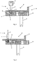
Fig. 1 is a longitudinal section of the locking mechanism for sliding doors and windows with key according to the present invention, the lock of said locking mechanism being in the blocked position; -
Fig. 2 is a longitudinal section of the locking mechanism for sliding doors and windows, the lock thereof being in the unblocked position; -
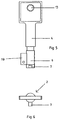
Fig. 3 is a side view of the lock with key in the unblocked position; -
Fig. 4 is a top view of the lock with key in the unblocked position; -
Fig. 5 is a side view of the lock with key in the blocked position; -
Fig. 6 is a top view of the lock with key in the blocked position; -
Fig. 7 is a longitudinal section view of the locking mechanism for sliding doors and windows with the lock in the blocked position; -
Fig. 8 is a top view of the locking mechanism for sliding doors and windows with the lock in the blocked position; -
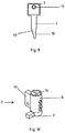
Fig. 9 is a view of the key; and -
Fig. 10 is an isometric view of the lock without key in the blocked position; -
Fig. 11a is a sectional top view of the locking mechanism for sliding doors and windows with the lock in the blocked position; -
Fig. 11b is a side view of the toggle box handle with the lock in the blocked position; -
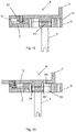
Fig. 12 is a longitudinal section of the locking mechanism for sliding doors and windows without key, the lock thereof being in the blocked position; -
Fig. 13 is a longitudinal section of the locking mechanism for sliding doors and windows without key, the lock thereof being in the unblocked position; -
Fig. 14a is a sectional view of the locking mechanism for sliding doors and windows inserted in a frame structure; -
Fig. 14b is a further view of the locking mechanism inserted in a frame structure; -
Fig. 14c is another view of the locking mechanism inserted in a frame structure; and -
Fig. 15 is a perspective view of the locking mechanism for sliding doors and windows inserted in a frame structure. - It will now be made a detailed description of a preferred embodiment of the
locking mechanism 18 for sliding doors and windows according to the present invention. - The
locking mechanism 18 for sliding doors and windows of the present invention has the advantage of allowing the blocking and the unblocking without restrictions nor limitations when inserted into frame structures, in particular structures of sliding windows or doors, it being able to be mounted in very small spaces without implications for the good working and/or performance of said sliding doors or windows, it being simpler and of smaller dimensions, easier to fabricate and having a cost more reduced with respect to existing locking mechanisms for that purpose. - Such as represented in
Fig. 1 , the upper portion of the blockingtoggle 8, of substantially rectangular shape and left and right smooth side faces 17, 17', includes anoperating handle 11 and the lower part of the blocking toggle includes atoggle box 10, anoperating latch 9, asecond chamber 12 and atrack 5. A user fits the key 1 in thekey hole 14, such as represented inFig. 1 , and rotates the same into 90° in the counter-clockwise direction. This action causes the displacement of thecylinder pin 7 from thestopper 20 in thetrack 5 to a position where it is aligned with thetab 19 and enables the movement of thetoggle 10. - Such as represented in
Fig. 2 , a user can again displace thetoggle 10 to the position shown inFig. 1 . Then the user can engage the key 1 in thekey hole 14 and rotate the same into 90° in the clockwise direction. This action causes the displacement of thecylinder pin 7 inside thetrack 5 to a position in which saidcylinder pin 7 is arranged into 90° with respect to thetab 19 and abutted onstopper 20, it being thus prevented the movement of thetoggle 10. - Particularly with respect to the cylinder pin and to the track on which it is displaced, they can take on other configurations within the scope of the invention, always in order to enable the blocking and unblocking of locking mechanisms inserted into frames that may enable an efficient working within the mentioned purposes.
- The above described embodiment is illustrative and it is not limitative. Many variations are possible to the locking mechanism for sliding doors and windows shown in the drawings, which are within the scope of this invention such as defined in the claims.
-
- 1
- - Key
- 2
- - Lock
- 3
- - Key head
- 4
- - Key shaft
- 5
- - Track
- 6
- - Lock cylinder
- 7
- - Cylinder pin
- 8
- - Blocking toggle
- 9
- - Operating latch
- 10
- - Toggle box
- 11
- - Operating handle
- 12
- - Second chamber
- 13
- - Bore
- 14
- - Key hole
- 15
- - Inlet
- 16
- - Key teeth
- 17,
- 17' - Left and right smooth side faces
- 18
- - Locking mechanism
- 19
- - Tab
- 20
- - Stopper
- 21
- - First chamber
- 22
- - Body portion
- 23
- - Third chamber
- 24
- - Screw
- 24'
- - Screw
- 25
- - Fourth chamber
Claims (3)
- Locking mechanism (18) for sliding doors and windows which comprises a lock (2) with a lock cylinder (6) having a key hole (14) for the key (1), characterized in that it comprises a tab (19) and a cylinder pin (7) integrated in said lock (2), a toggle box (10), a track (5), a stopper (20), a second chamber (12), an operating latch (9), a blocking toggle (8), an operating handle (11), left and right side faces (17, 17'), a first chamber (21), a body portion (22), a third chamber (23), a fourth chamber (25) and screws (24, 24'), wherein:the lock (2) is inserted close to the left side face (17) of said blocking toggle (8);the operating handle (11) of said blocking toggle (8) is arranged in order to be extended outwardly in a straight line in the vicinity of said right side face (17');the tab (19) is partially housed in a first chamber (21) and partially housed in a second chamber (12);the tab (19) is arranged in order to be prevented from displacing in said first chamber (21);the tab (19) is disposed in order to be displaced in said second chamber (12);the cylinder pin (7) is arranged to be displaced in the track (5), when it is aligned with said tab (19) in the unblocking position of said locking mechanism (18);the cylinder pin (7) is arranged in order to be abutted against a stopper (20) which is aligned with said track (5), when the tab (19) is arranged perpendicularly with respect to the cylinder pin (7) in the blocking position of said locking mechanism (18);the operating latch (9) is arranged in order to be displaced together with the blocking toggle (8);the blocking toggle (8) is arranged in such a way with respect to the toggle box (10) that its longitudinal movement is effected by the displacement of said operating handle (11);the body portion (22) of the blocking toggle (8) is joined attached to this latter by means of the screws (24, 24');the third chamber (23) and the fourth chamber (25) are arranged in such a way that they allow the movement of said body portion (22) and of the body portion adjacent part (22'); andthe left and right side faces (17, 17') of the blocking toggle are substantially smooth.
- Locking mechanism (18) for sliding doors and windows according to claim 1, characterized in that the width of said locking mechanism (18) is greatly reduced, preferably in the order of 14 mm.
- Locking mechanism (18) for sliding doors and windows according to claim 1, characterized in that the diameter of said lock (2) is greatly reduced, preferably in the order of 6 mm.
Priority Applications (3)
| Application Number | Priority Date | Filing Date | Title |
|---|---|---|---|
| PT193980067T PT3739151T (en) | 2019-05-17 | 2019-05-17 | Locking mechanism for sliding doors and windows |
| EP19398006.7A EP3739151B1 (en) | 2019-05-17 | 2019-05-17 | Locking mechanism for sliding doors and windows |
| US16/854,949 US20200362597A1 (en) | 2019-05-17 | 2020-04-22 | Locking mechanism for sliding doors and windows |
Applications Claiming Priority (1)
| Application Number | Priority Date | Filing Date | Title |
|---|---|---|---|
| EP19398006.7A EP3739151B1 (en) | 2019-05-17 | 2019-05-17 | Locking mechanism for sliding doors and windows |
Publications (2)
| Publication Number | Publication Date |
|---|---|
| EP3739151A1 true EP3739151A1 (en) | 2020-11-18 |
| EP3739151B1 EP3739151B1 (en) | 2024-05-22 |
Family
ID=66668862
Family Applications (1)
| Application Number | Title | Priority Date | Filing Date |
|---|---|---|---|
| EP19398006.7A Active EP3739151B1 (en) | 2019-05-17 | 2019-05-17 | Locking mechanism for sliding doors and windows |
Country Status (3)
| Country | Link |
|---|---|
| US (1) | US20200362597A1 (en) |
| EP (1) | EP3739151B1 (en) |
| PT (1) | PT3739151T (en) |
Cited By (1)
| Publication number | Priority date | Publication date | Assignee | Title |
|---|---|---|---|---|
| CN114776139A (en) * | 2022-06-01 | 2022-07-22 | 慈溪市大嘉五金有限公司 | Handle lock applied to door and window |
Families Citing this family (1)
| Publication number | Priority date | Publication date | Assignee | Title |
|---|---|---|---|---|
| CN116591546B (en) * | 2023-06-25 | 2025-10-24 | 深圳好博窗控技术股份有限公司 | Door and window handle structure |
Citations (2)
| Publication number | Priority date | Publication date | Assignee | Title |
|---|---|---|---|---|
| US3120748A (en) * | 1960-10-11 | 1964-02-11 | Adams Rite Mfg Company | Narrow stile lock and actuator |
| EP1676969A2 (en) * | 2004-12-29 | 2006-07-05 | A.C. Technometal Ltd. | Catch locking mechanism featuring a key mechanism with lock failsafe system and high resistance against forced entry. |
Family Cites Families (15)
| Publication number | Priority date | Publication date | Assignee | Title |
|---|---|---|---|---|
| US818143A (en) * | 1905-10-26 | 1906-04-17 | William H Booth | Sliding-door fastener. |
| US3262292A (en) * | 1964-06-19 | 1966-07-26 | Nat Lock Co | Lock assembly for showcases and other closures |
| US3580016A (en) * | 1970-04-15 | 1971-05-25 | Chicago Lock Co | Keeper lock for a slide fastener |
| US3931723A (en) * | 1975-04-03 | 1976-01-13 | Kurtz Thomas D | Lock for sliding closure panels |
| US4154467A (en) * | 1977-10-13 | 1979-05-15 | Beard Eugene R | Panel mounted exterior keyed lock for sliding door and windows |
| US4356580A (en) * | 1980-10-20 | 1982-11-02 | Kurtz Thomas D | Showcase lock for sliding doors |
| US4641506A (en) * | 1985-04-09 | 1987-02-10 | Hudson Lock, Inc. | Sliding bolt locking device |
| FR2619592A2 (en) * | 1987-03-24 | 1989-02-24 | Velay Moulages | Device for locking in position at least two elements which can move with respect to each other |
| US5145221A (en) * | 1990-07-17 | 1992-09-08 | Chicago Electrical Tool Company, Inc. | Sliding latch lock |
| US5315850A (en) * | 1993-03-22 | 1994-05-31 | National Manufacturing Company | Surface mounted slide bolt |
| FR2761724B1 (en) * | 1997-04-03 | 2000-02-04 | Ferco Int Usine Ferrures | LOCKING HARDWARE FOR SLIDING DOOR, WINDOW OR THE LIKE |
| US6920770B2 (en) * | 2003-06-03 | 2005-07-26 | Alan E. Lurie | Plunger lock assembly with removable core |
| US7373794B1 (en) * | 2005-06-21 | 2008-05-20 | Delta Industrial Systems Corp. | Lock assembly |
| US9097038B1 (en) * | 2011-10-14 | 2015-08-04 | Kevin M. Cohen | Slide lock device |
| US20130228296A1 (en) * | 2012-03-02 | 2013-09-05 | Harmony Products, Inc. | Window security screen and latch assembly |
-
2019
- 2019-05-17 PT PT193980067T patent/PT3739151T/en unknown
- 2019-05-17 EP EP19398006.7A patent/EP3739151B1/en active Active
-
2020
- 2020-04-22 US US16/854,949 patent/US20200362597A1/en not_active Abandoned
Patent Citations (2)
| Publication number | Priority date | Publication date | Assignee | Title |
|---|---|---|---|---|
| US3120748A (en) * | 1960-10-11 | 1964-02-11 | Adams Rite Mfg Company | Narrow stile lock and actuator |
| EP1676969A2 (en) * | 2004-12-29 | 2006-07-05 | A.C. Technometal Ltd. | Catch locking mechanism featuring a key mechanism with lock failsafe system and high resistance against forced entry. |
Cited By (1)
| Publication number | Priority date | Publication date | Assignee | Title |
|---|---|---|---|---|
| CN114776139A (en) * | 2022-06-01 | 2022-07-22 | 慈溪市大嘉五金有限公司 | Handle lock applied to door and window |
Also Published As
| Publication number | Publication date |
|---|---|
| PT3739151T (en) | 2024-06-03 |
| EP3739151B1 (en) | 2024-05-22 |
| US20200362597A1 (en) | 2020-11-19 |
Similar Documents
| Publication | Publication Date | Title |
|---|---|---|
| US20060208509A1 (en) | 360 Degree adjustable deadbolt assembly | |
| US10094142B2 (en) | Adjustable dead-latching bolt mechanism | |
| EP2029839B1 (en) | Disc tumbler cylinder lock and key combination | |
| EP3739151B1 (en) | Locking mechanism for sliding doors and windows | |
| US4296618A (en) | Lock and key device | |
| US6983962B2 (en) | Deadlock arrangement for locks | |
| EA015020B1 (en) | Security lock hook-shape latch reinforcement pins | |
| US9194166B1 (en) | Modified door hinge comprising locking mechanism | |
| EP2463458B1 (en) | Bolt arrangement for a lock body | |
| GB2549193A (en) | A lock | |
| US8485569B2 (en) | Lock assembly | |
| KR20140104167A (en) | Door-lock having rotated hook | |
| US20070052250A1 (en) | One-piece cam and bolt housing for a deadbolt assembly | |
| KR20250015831A (en) | Inverted blocker rack and pinion | |
| US5682778A (en) | Lead-in device for aiding the installation of rim-type lock cylinders | |
| EP1483471B1 (en) | Safety lock for glass doors | |
| CN112878807B (en) | A lock body and a lock | |
| KR100427402B1 (en) | Locking apparatus for opening and shutting door | |
| CN116517402A (en) | lock assembly | |
| JP5787552B2 (en) | Locking device | |
| CN104929430A (en) | a tumbler lock | |
| CN211549145U (en) | Sliding door lock reversing mechanism and sliding door lock | |
| CN210239369U (en) | Linkage mechanism for lock and lock | |
| KR101383622B1 (en) | Safety locking assembly for push-pull doorlock | |
| CN106677618A (en) | Anti-theft lock |
Legal Events
| Date | Code | Title | Description |
|---|---|---|---|
| PUAI | Public reference made under article 153(3) epc to a published international application that has entered the european phase |
Free format text: ORIGINAL CODE: 0009012 |
|
| STAA | Information on the status of an ep patent application or granted ep patent |
Free format text: STATUS: THE APPLICATION HAS BEEN PUBLISHED |
|
| AK | Designated contracting states |
Kind code of ref document: A1 Designated state(s): AL AT BE BG CH CY CZ DE DK EE ES FI FR GB GR HR HU IE IS IT LI LT LU LV MC MK MT NL NO PL PT RO RS SE SI SK SM TR |
|
| AX | Request for extension of the european patent |
Extension state: BA ME |
|
| STAA | Information on the status of an ep patent application or granted ep patent |
Free format text: STATUS: REQUEST FOR EXAMINATION WAS MADE |
|
| 17P | Request for examination filed |
Effective date: 20210408 |
|
| RBV | Designated contracting states (corrected) |
Designated state(s): AL AT BE BG CH CY CZ DE DK EE ES FI FR GB GR HR HU IE IS IT LI LT LU LV MC MK MT NL NO PL PT RO RS SE SI SK SM TR |
|
| RIN1 | Information on inventor provided before grant (corrected) |
Inventor name: TAVARES NUNES, ANTONIO MANUEL |
|
| GRAP | Despatch of communication of intention to grant a patent |
Free format text: ORIGINAL CODE: EPIDOSNIGR1 |
|
| STAA | Information on the status of an ep patent application or granted ep patent |
Free format text: STATUS: GRANT OF PATENT IS INTENDED |
|
| INTG | Intention to grant announced |
Effective date: 20231218 |
|
| GRAS | Grant fee paid |
Free format text: ORIGINAL CODE: EPIDOSNIGR3 |
|
| GRAA | (expected) grant |
Free format text: ORIGINAL CODE: 0009210 |
|
| STAA | Information on the status of an ep patent application or granted ep patent |
Free format text: STATUS: THE PATENT HAS BEEN GRANTED |
|
| AK | Designated contracting states |
Kind code of ref document: B1 Designated state(s): AL AT BE BG CH CY CZ DE DK EE ES FI FR GB GR HR HU IE IS IT LI LT LU LV MC MK MT NL NO PL PT RO RS SE SI SK SM TR |
|
| REG | Reference to a national code |
Ref country code: GB Ref legal event code: FG4D |
|
| REG | Reference to a national code |
Ref country code: CH Ref legal event code: EP |
|
| REG | Reference to a national code |
Ref country code: PT Ref legal event code: SC4A Ref document number: 3739151 Country of ref document: PT Date of ref document: 20240603 Kind code of ref document: T Free format text: AVAILABILITY OF NATIONAL TRANSLATION Effective date: 20240527 |
|
| REG | Reference to a national code |
Ref country code: DE Ref legal event code: R096 Ref document number: 602019052548 Country of ref document: DE |
|
| REG | Reference to a national code |
Ref country code: IE Ref legal event code: FG4D |
|
| P01 | Opt-out of the competence of the unified patent court (upc) registered |
Free format text: CASE NUMBER: APP_34045/2024 Effective date: 20240606 |
|
| REG | Reference to a national code |
Ref country code: LT Ref legal event code: MG9D |
|
| REG | Reference to a national code |
Ref country code: NL Ref legal event code: MP Effective date: 20240522 |
|
| PG25 | Lapsed in a contracting state [announced via postgrant information from national office to epo] |
Ref country code: IS Free format text: LAPSE BECAUSE OF FAILURE TO SUBMIT A TRANSLATION OF THE DESCRIPTION OR TO PAY THE FEE WITHIN THE PRESCRIBED TIME-LIMIT Effective date: 20240922 |
|
| PG25 | Lapsed in a contracting state [announced via postgrant information from national office to epo] |
Ref country code: BG Free format text: LAPSE BECAUSE OF FAILURE TO SUBMIT A TRANSLATION OF THE DESCRIPTION OR TO PAY THE FEE WITHIN THE PRESCRIBED TIME-LIMIT Effective date: 20240522 |
|
| PG25 | Lapsed in a contracting state [announced via postgrant information from national office to epo] |
Ref country code: HR Free format text: LAPSE BECAUSE OF FAILURE TO SUBMIT A TRANSLATION OF THE DESCRIPTION OR TO PAY THE FEE WITHIN THE PRESCRIBED TIME-LIMIT Effective date: 20240522 Ref country code: FI Free format text: LAPSE BECAUSE OF FAILURE TO SUBMIT A TRANSLATION OF THE DESCRIPTION OR TO PAY THE FEE WITHIN THE PRESCRIBED TIME-LIMIT Effective date: 20240522 |
|
| PG25 | Lapsed in a contracting state [announced via postgrant information from national office to epo] |
Ref country code: GR Free format text: LAPSE BECAUSE OF FAILURE TO SUBMIT A TRANSLATION OF THE DESCRIPTION OR TO PAY THE FEE WITHIN THE PRESCRIBED TIME-LIMIT Effective date: 20240823 |
|
| REG | Reference to a national code |
Ref country code: AT Ref legal event code: MK05 Ref document number: 1688891 Country of ref document: AT Kind code of ref document: T Effective date: 20240522 |
|
| PG25 | Lapsed in a contracting state [announced via postgrant information from national office to epo] |
Ref country code: NL Free format text: LAPSE BECAUSE OF FAILURE TO SUBMIT A TRANSLATION OF THE DESCRIPTION OR TO PAY THE FEE WITHIN THE PRESCRIBED TIME-LIMIT Effective date: 20240522 |
|
| PG25 | Lapsed in a contracting state [announced via postgrant information from national office to epo] |
Ref country code: ES Free format text: LAPSE BECAUSE OF FAILURE TO SUBMIT A TRANSLATION OF THE DESCRIPTION OR TO PAY THE FEE WITHIN THE PRESCRIBED TIME-LIMIT Effective date: 20240522 |
|
| PG25 | Lapsed in a contracting state [announced via postgrant information from national office to epo] |
Ref country code: AT Free format text: LAPSE BECAUSE OF FAILURE TO SUBMIT A TRANSLATION OF THE DESCRIPTION OR TO PAY THE FEE WITHIN THE PRESCRIBED TIME-LIMIT Effective date: 20240522 |
|
| PG25 | Lapsed in a contracting state [announced via postgrant information from national office to epo] |
Ref country code: PL Free format text: LAPSE BECAUSE OF FAILURE TO SUBMIT A TRANSLATION OF THE DESCRIPTION OR TO PAY THE FEE WITHIN THE PRESCRIBED TIME-LIMIT Effective date: 20240522 |
|
| PG25 | Lapsed in a contracting state [announced via postgrant information from national office to epo] |
Ref country code: LV Free format text: LAPSE BECAUSE OF FAILURE TO SUBMIT A TRANSLATION OF THE DESCRIPTION OR TO PAY THE FEE WITHIN THE PRESCRIBED TIME-LIMIT Effective date: 20240522 |
|
| PG25 | Lapsed in a contracting state [announced via postgrant information from national office to epo] |
Ref country code: PL Free format text: LAPSE BECAUSE OF FAILURE TO SUBMIT A TRANSLATION OF THE DESCRIPTION OR TO PAY THE FEE WITHIN THE PRESCRIBED TIME-LIMIT Effective date: 20240522 Ref country code: NO Free format text: LAPSE BECAUSE OF FAILURE TO SUBMIT A TRANSLATION OF THE DESCRIPTION OR TO PAY THE FEE WITHIN THE PRESCRIBED TIME-LIMIT Effective date: 20240822 Ref country code: NL Free format text: LAPSE BECAUSE OF FAILURE TO SUBMIT A TRANSLATION OF THE DESCRIPTION OR TO PAY THE FEE WITHIN THE PRESCRIBED TIME-LIMIT Effective date: 20240522 Ref country code: LV Free format text: LAPSE BECAUSE OF FAILURE TO SUBMIT A TRANSLATION OF THE DESCRIPTION OR TO PAY THE FEE WITHIN THE PRESCRIBED TIME-LIMIT Effective date: 20240522 Ref country code: IS Free format text: LAPSE BECAUSE OF FAILURE TO SUBMIT A TRANSLATION OF THE DESCRIPTION OR TO PAY THE FEE WITHIN THE PRESCRIBED TIME-LIMIT Effective date: 20240922 Ref country code: HR Free format text: LAPSE BECAUSE OF FAILURE TO SUBMIT A TRANSLATION OF THE DESCRIPTION OR TO PAY THE FEE WITHIN THE PRESCRIBED TIME-LIMIT Effective date: 20240522 Ref country code: GR Free format text: LAPSE BECAUSE OF FAILURE TO SUBMIT A TRANSLATION OF THE DESCRIPTION OR TO PAY THE FEE WITHIN THE PRESCRIBED TIME-LIMIT Effective date: 20240823 Ref country code: FI Free format text: LAPSE BECAUSE OF FAILURE TO SUBMIT A TRANSLATION OF THE DESCRIPTION OR TO PAY THE FEE WITHIN THE PRESCRIBED TIME-LIMIT Effective date: 20240522 Ref country code: ES Free format text: LAPSE BECAUSE OF FAILURE TO SUBMIT A TRANSLATION OF THE DESCRIPTION OR TO PAY THE FEE WITHIN THE PRESCRIBED TIME-LIMIT Effective date: 20240522 Ref country code: BG Free format text: LAPSE BECAUSE OF FAILURE TO SUBMIT A TRANSLATION OF THE DESCRIPTION OR TO PAY THE FEE WITHIN THE PRESCRIBED TIME-LIMIT Effective date: 20240522 Ref country code: AT Free format text: LAPSE BECAUSE OF FAILURE TO SUBMIT A TRANSLATION OF THE DESCRIPTION OR TO PAY THE FEE WITHIN THE PRESCRIBED TIME-LIMIT Effective date: 20240522 Ref country code: RS Free format text: LAPSE BECAUSE OF FAILURE TO SUBMIT A TRANSLATION OF THE DESCRIPTION OR TO PAY THE FEE WITHIN THE PRESCRIBED TIME-LIMIT Effective date: 20240822 |
|
| PG25 | Lapsed in a contracting state [announced via postgrant information from national office to epo] |
Ref country code: DK Free format text: LAPSE BECAUSE OF FAILURE TO SUBMIT A TRANSLATION OF THE DESCRIPTION OR TO PAY THE FEE WITHIN THE PRESCRIBED TIME-LIMIT Effective date: 20240522 |
|
| PG25 | Lapsed in a contracting state [announced via postgrant information from national office to epo] |
Ref country code: EE Free format text: LAPSE BECAUSE OF FAILURE TO SUBMIT A TRANSLATION OF THE DESCRIPTION OR TO PAY THE FEE WITHIN THE PRESCRIBED TIME-LIMIT Effective date: 20240522 |
|
| PG25 | Lapsed in a contracting state [announced via postgrant information from national office to epo] |
Ref country code: CZ Free format text: LAPSE BECAUSE OF FAILURE TO SUBMIT A TRANSLATION OF THE DESCRIPTION OR TO PAY THE FEE WITHIN THE PRESCRIBED TIME-LIMIT Effective date: 20240522 |
|
| PG25 | Lapsed in a contracting state [announced via postgrant information from national office to epo] |
Ref country code: RO Free format text: LAPSE BECAUSE OF FAILURE TO SUBMIT A TRANSLATION OF THE DESCRIPTION OR TO PAY THE FEE WITHIN THE PRESCRIBED TIME-LIMIT Effective date: 20240522 Ref country code: SK Free format text: LAPSE BECAUSE OF FAILURE TO SUBMIT A TRANSLATION OF THE DESCRIPTION OR TO PAY THE FEE WITHIN THE PRESCRIBED TIME-LIMIT Effective date: 20240522 |
|
| PG25 | Lapsed in a contracting state [announced via postgrant information from national office to epo] |
Ref country code: SM Free format text: LAPSE BECAUSE OF FAILURE TO SUBMIT A TRANSLATION OF THE DESCRIPTION OR TO PAY THE FEE WITHIN THE PRESCRIBED TIME-LIMIT Effective date: 20240522 |
|
| PG25 | Lapsed in a contracting state [announced via postgrant information from national office to epo] |
Ref country code: SM Free format text: LAPSE BECAUSE OF FAILURE TO SUBMIT A TRANSLATION OF THE DESCRIPTION OR TO PAY THE FEE WITHIN THE PRESCRIBED TIME-LIMIT Effective date: 20240522 Ref country code: SK Free format text: LAPSE BECAUSE OF FAILURE TO SUBMIT A TRANSLATION OF THE DESCRIPTION OR TO PAY THE FEE WITHIN THE PRESCRIBED TIME-LIMIT Effective date: 20240522 Ref country code: RO Free format text: LAPSE BECAUSE OF FAILURE TO SUBMIT A TRANSLATION OF THE DESCRIPTION OR TO PAY THE FEE WITHIN THE PRESCRIBED TIME-LIMIT Effective date: 20240522 Ref country code: EE Free format text: LAPSE BECAUSE OF FAILURE TO SUBMIT A TRANSLATION OF THE DESCRIPTION OR TO PAY THE FEE WITHIN THE PRESCRIBED TIME-LIMIT Effective date: 20240522 Ref country code: DK Free format text: LAPSE BECAUSE OF FAILURE TO SUBMIT A TRANSLATION OF THE DESCRIPTION OR TO PAY THE FEE WITHIN THE PRESCRIBED TIME-LIMIT Effective date: 20240522 Ref country code: CZ Free format text: LAPSE BECAUSE OF FAILURE TO SUBMIT A TRANSLATION OF THE DESCRIPTION OR TO PAY THE FEE WITHIN THE PRESCRIBED TIME-LIMIT Effective date: 20240522 |
|
| PG25 | Lapsed in a contracting state [announced via postgrant information from national office to epo] |
Ref country code: IT Free format text: LAPSE BECAUSE OF FAILURE TO SUBMIT A TRANSLATION OF THE DESCRIPTION OR TO PAY THE FEE WITHIN THE PRESCRIBED TIME-LIMIT Effective date: 20240522 |
|
| REG | Reference to a national code |
Ref country code: DE Ref legal event code: R097 Ref document number: 602019052548 Country of ref document: DE |
|
| PLBE | No opposition filed within time limit |
Free format text: ORIGINAL CODE: 0009261 |
|
| STAA | Information on the status of an ep patent application or granted ep patent |
Free format text: STATUS: NO OPPOSITION FILED WITHIN TIME LIMIT |
|
| PG25 | Lapsed in a contracting state [announced via postgrant information from national office to epo] |
Ref country code: SI Free format text: LAPSE BECAUSE OF FAILURE TO SUBMIT A TRANSLATION OF THE DESCRIPTION OR TO PAY THE FEE WITHIN THE PRESCRIBED TIME-LIMIT Effective date: 20240522 |
|
| 26N | No opposition filed |
Effective date: 20250225 |
|
| PGFP | Annual fee paid to national office [announced via postgrant information from national office to epo] |
Ref country code: CH Payment date: 20250601 Year of fee payment: 7 |
|
| PG25 | Lapsed in a contracting state [announced via postgrant information from national office to epo] |
Ref country code: SE Free format text: LAPSE BECAUSE OF FAILURE TO SUBMIT A TRANSLATION OF THE DESCRIPTION OR TO PAY THE FEE WITHIN THE PRESCRIBED TIME-LIMIT Effective date: 20240522 |
|
| REG | Reference to a national code |
Ref country code: DE Ref legal event code: R119 Ref document number: 602019052548 Country of ref document: DE |
|
| PGFP | Annual fee paid to national office [announced via postgrant information from national office to epo] |
Ref country code: PT Payment date: 20251202 Year of fee payment: 8 |
|
| PG25 | Lapsed in a contracting state [announced via postgrant information from national office to epo] |
Ref country code: LU Free format text: LAPSE BECAUSE OF NON-PAYMENT OF DUE FEES Effective date: 20250517 |
|
| GBPC | Gb: european patent ceased through non-payment of renewal fee |
Effective date: 20250517 |
|
| REG | Reference to a national code |
Ref country code: BE Ref legal event code: MM Effective date: 20250531 |
|
| PG25 | Lapsed in a contracting state [announced via postgrant information from national office to epo] |
Ref country code: MC Free format text: LAPSE BECAUSE OF FAILURE TO SUBMIT A TRANSLATION OF THE DESCRIPTION OR TO PAY THE FEE WITHIN THE PRESCRIBED TIME-LIMIT Effective date: 20240522 |
|
| PG25 | Lapsed in a contracting state [announced via postgrant information from national office to epo] |
Ref country code: GB Free format text: LAPSE BECAUSE OF NON-PAYMENT OF DUE FEES Effective date: 20250517 |
|
| PG25 | Lapsed in a contracting state [announced via postgrant information from national office to epo] |
Ref country code: IE Free format text: LAPSE BECAUSE OF NON-PAYMENT OF DUE FEES Effective date: 20250517 Ref country code: DE Free format text: LAPSE BECAUSE OF NON-PAYMENT OF DUE FEES Effective date: 20251202 |
|
| PG25 | Lapsed in a contracting state [announced via postgrant information from national office to epo] |
Ref country code: BE Free format text: LAPSE BECAUSE OF NON-PAYMENT OF DUE FEES Effective date: 20250531 |
|
| PG25 | Lapsed in a contracting state [announced via postgrant information from national office to epo] |
Ref country code: FR Free format text: LAPSE BECAUSE OF NON-PAYMENT OF DUE FEES Effective date: 20250531 |