EP3739024A1 - Rubber material recovery method and oil product - Google Patents
Rubber material recovery method and oil product Download PDFInfo
- Publication number
- EP3739024A1 EP3739024A1 EP20155820.2A EP20155820A EP3739024A1 EP 3739024 A1 EP3739024 A1 EP 3739024A1 EP 20155820 A EP20155820 A EP 20155820A EP 3739024 A1 EP3739024 A1 EP 3739024A1
- Authority
- EP
- European Patent Office
- Prior art keywords
- rubber material
- oil product
- softener
- rubber
- hardness
- Prior art date
- Legal status (The legal status is an assumption and is not a legal conclusion. Google has not performed a legal analysis and makes no representation as to the accuracy of the status listed.)
- Withdrawn
Links
- 229920001971 elastomer Polymers 0.000 title claims abstract description 429
- 239000000463 material Substances 0.000 title claims abstract description 411
- 238000000034 method Methods 0.000 title claims abstract description 57
- 238000011084 recovery Methods 0.000 title claims abstract description 20
- 239000003921 oil Substances 0.000 claims description 279
- 229920001084 poly(chloroprene) Polymers 0.000 claims description 48
- 229920000459 Nitrile rubber Polymers 0.000 claims description 38
- 239000010730 cutting oil Substances 0.000 claims description 22
- 229920001973 fluoroelastomer Polymers 0.000 claims description 21
- 238000007789 sealing Methods 0.000 claims description 20
- 239000003795 chemical substances by application Substances 0.000 claims description 17
- 238000005057 refrigeration Methods 0.000 claims description 15
- 239000002199 base oil Substances 0.000 claims description 11
- 239000004519 grease Substances 0.000 claims description 11
- 238000012546 transfer Methods 0.000 claims description 11
- 238000001816 cooling Methods 0.000 claims description 10
- 239000000314 lubricant Substances 0.000 claims description 9
- 239000000446 fuel Substances 0.000 claims description 8
- 230000005540 biological transmission Effects 0.000 claims description 7
- 238000005461 lubrication Methods 0.000 claims description 7
- 150000002825 nitriles Chemical class 0.000 claims description 2
- 235000019198 oils Nutrition 0.000 description 241
- 239000000047 product Substances 0.000 description 210
- 238000012360 testing method Methods 0.000 description 44
- 238000004891 communication Methods 0.000 description 40
- 230000032683 aging Effects 0.000 description 34
- 238000010586 diagram Methods 0.000 description 20
- 230000008859 change Effects 0.000 description 14
- 230000000694 effects Effects 0.000 description 13
- 239000003507 refrigerant Substances 0.000 description 12
- 239000007921 spray Substances 0.000 description 10
- 238000005507 spraying Methods 0.000 description 9
- 239000000654 additive Substances 0.000 description 8
- -1 aliphatic diester Chemical class 0.000 description 8
- 230000002123 temporal effect Effects 0.000 description 8
- 230000000996 additive effect Effects 0.000 description 7
- 238000003754 machining Methods 0.000 description 5
- 239000002904 solvent Substances 0.000 description 5
- 238000007654 immersion Methods 0.000 description 4
- 239000002184 metal Substances 0.000 description 4
- 238000007639 printing Methods 0.000 description 4
- 230000008569 process Effects 0.000 description 4
- 230000009467 reduction Effects 0.000 description 4
- 230000008602 contraction Effects 0.000 description 3
- 150000002148 esters Chemical class 0.000 description 3
- 239000004014 plasticizer Substances 0.000 description 3
- ARXJGSRGQADJSQ-UHFFFAOYSA-N 1-methoxypropan-2-ol Chemical compound COCC(C)O ARXJGSRGQADJSQ-UHFFFAOYSA-N 0.000 description 2
- 239000003638 chemical reducing agent Substances 0.000 description 2
- 230000007423 decrease Effects 0.000 description 2
- 239000012530 fluid Substances 0.000 description 2
- 239000007791 liquid phase Substances 0.000 description 2
- 239000000203 mixture Substances 0.000 description 2
- 238000003466 welding Methods 0.000 description 2
- 239000004215 Carbon black (E152) Substances 0.000 description 1
- LFQSCWFLJHTTHZ-UHFFFAOYSA-N Ethanol Chemical compound CCO LFQSCWFLJHTTHZ-UHFFFAOYSA-N 0.000 description 1
- UFWIBTONFRDIAS-UHFFFAOYSA-N Naphthalene Chemical compound C1=CC=CC2=CC=CC=C21 UFWIBTONFRDIAS-UHFFFAOYSA-N 0.000 description 1
- OAICVXFJPJFONN-UHFFFAOYSA-N Phosphorus Chemical compound [P] OAICVXFJPJFONN-UHFFFAOYSA-N 0.000 description 1
- NINIDFKCEFEMDL-UHFFFAOYSA-N Sulfur Chemical compound [S] NINIDFKCEFEMDL-UHFFFAOYSA-N 0.000 description 1
- 239000002253 acid Substances 0.000 description 1
- 238000004378 air conditioning Methods 0.000 description 1
- 125000001931 aliphatic group Chemical group 0.000 description 1
- 239000010775 animal oil Substances 0.000 description 1
- 239000002518 antifoaming agent Substances 0.000 description 1
- 239000003963 antioxidant agent Substances 0.000 description 1
- 229940071160 cocoate Drugs 0.000 description 1
- 238000005260 corrosion Methods 0.000 description 1
- 230000007797 corrosion Effects 0.000 description 1
- 238000005520 cutting process Methods 0.000 description 1
- 239000003599 detergent Substances 0.000 description 1
- 235000014113 dietary fatty acids Nutrition 0.000 description 1
- HBGGXOJOCNVPFY-UHFFFAOYSA-N diisononyl phthalate Chemical compound CC(C)CCCCCCOC(=O)C1=CC=CC=C1C(=O)OCCCCCCC(C)C HBGGXOJOCNVPFY-UHFFFAOYSA-N 0.000 description 1
- 239000002270 dispersing agent Substances 0.000 description 1
- 239000000428 dust Substances 0.000 description 1
- 238000001704 evaporation Methods 0.000 description 1
- 239000000194 fatty acid Substances 0.000 description 1
- 229930195729 fatty acid Natural products 0.000 description 1
- 150000004665 fatty acids Chemical class 0.000 description 1
- 238000010438 heat treatment Methods 0.000 description 1
- 239000010720 hydraulic oil Substances 0.000 description 1
- 229930195733 hydrocarbon Natural products 0.000 description 1
- 150000002430 hydrocarbons Chemical class 0.000 description 1
- 238000005470 impregnation Methods 0.000 description 1
- 239000003112 inhibitor Substances 0.000 description 1
- 239000007788 liquid Substances 0.000 description 1
- 239000002480 mineral oil Substances 0.000 description 1
- 235000010446 mineral oil Nutrition 0.000 description 1
- 238000012986 modification Methods 0.000 description 1
- 230000004048 modification Effects 0.000 description 1
- 239000004745 nonwoven fabric Substances 0.000 description 1
- XNGIFLGASWRNHJ-UHFFFAOYSA-N o-dicarboxybenzene Natural products OC(=O)C1=CC=CC=C1C(O)=O XNGIFLGASWRNHJ-UHFFFAOYSA-N 0.000 description 1
- 230000002093 peripheral effect Effects 0.000 description 1
- 239000012466 permeate Substances 0.000 description 1
- 239000012071 phase Substances 0.000 description 1
- NBIIXXVUZAFLBC-UHFFFAOYSA-N phosphoric acid Substances OP(O)(O)=O NBIIXXVUZAFLBC-UHFFFAOYSA-N 0.000 description 1
- 235000011007 phosphoric acid Nutrition 0.000 description 1
- 239000011574 phosphorus Substances 0.000 description 1
- 229910052698 phosphorus Inorganic materials 0.000 description 1
- 230000000704 physical effect Effects 0.000 description 1
- 229920013639 polyalphaolefin Polymers 0.000 description 1
- 229920001083 polybutene Polymers 0.000 description 1
- 235000012424 soybean oil Nutrition 0.000 description 1
- 239000003549 soybean oil Substances 0.000 description 1
- 239000000126 substance Substances 0.000 description 1
- 239000011593 sulfur Substances 0.000 description 1
- 229910052717 sulfur Inorganic materials 0.000 description 1
- 239000002562 thickening agent Substances 0.000 description 1
- 235000015112 vegetable and seed oil Nutrition 0.000 description 1
- 239000008158 vegetable oil Substances 0.000 description 1
- 125000000391 vinyl group Chemical group [H]C([*])=C([H])[H] 0.000 description 1
- 229920002554 vinyl polymer Polymers 0.000 description 1
- XLYOFNOQVPJJNP-UHFFFAOYSA-N water Substances O XLYOFNOQVPJJNP-UHFFFAOYSA-N 0.000 description 1
- 239000002759 woven fabric Substances 0.000 description 1
Images











Classifications
-
- C—CHEMISTRY; METALLURGY
- C08—ORGANIC MACROMOLECULAR COMPOUNDS; THEIR PREPARATION OR CHEMICAL WORKING-UP; COMPOSITIONS BASED THEREON
- C08J—WORKING-UP; GENERAL PROCESSES OF COMPOUNDING; AFTER-TREATMENT NOT COVERED BY SUBCLASSES C08B, C08C, C08F, C08G or C08H
- C08J11/00—Recovery or working-up of waste materials
- C08J11/04—Recovery or working-up of waste materials of polymers
- C08J11/10—Recovery or working-up of waste materials of polymers by chemically breaking down the molecular chains of polymers or breaking of crosslinks, e.g. devulcanisation
- C08J11/18—Recovery or working-up of waste materials of polymers by chemically breaking down the molecular chains of polymers or breaking of crosslinks, e.g. devulcanisation by treatment with organic material
- C08J11/22—Recovery or working-up of waste materials of polymers by chemically breaking down the molecular chains of polymers or breaking of crosslinks, e.g. devulcanisation by treatment with organic material by treatment with organic oxygen-containing compounds
- C08J11/26—Recovery or working-up of waste materials of polymers by chemically breaking down the molecular chains of polymers or breaking of crosslinks, e.g. devulcanisation by treatment with organic material by treatment with organic oxygen-containing compounds containing carboxylic acid groups, their anhydrides or esters
-
- C—CHEMISTRY; METALLURGY
- C10—PETROLEUM, GAS OR COKE INDUSTRIES; TECHNICAL GASES CONTAINING CARBON MONOXIDE; FUELS; LUBRICANTS; PEAT
- C10M—LUBRICATING COMPOSITIONS; USE OF CHEMICAL SUBSTANCES EITHER ALONE OR AS LUBRICATING INGREDIENTS IN A LUBRICATING COMPOSITION
- C10M171/00—Lubricating compositions characterised by purely physical criteria, e.g. containing as base-material, thickener or additive, ingredients which are characterised exclusively by their numerically specified physical properties, i.e. containing ingredients which are physically well-defined but for which the chemical nature is either unspecified or only very vaguely indicated
-
- C—CHEMISTRY; METALLURGY
- C08—ORGANIC MACROMOLECULAR COMPOUNDS; THEIR PREPARATION OR CHEMICAL WORKING-UP; COMPOSITIONS BASED THEREON
- C08J—WORKING-UP; GENERAL PROCESSES OF COMPOUNDING; AFTER-TREATMENT NOT COVERED BY SUBCLASSES C08B, C08C, C08F, C08G or C08H
- C08J7/00—Chemical treatment or coating of shaped articles made of macromolecular substances
-
- C—CHEMISTRY; METALLURGY
- C08—ORGANIC MACROMOLECULAR COMPOUNDS; THEIR PREPARATION OR CHEMICAL WORKING-UP; COMPOSITIONS BASED THEREON
- C08J—WORKING-UP; GENERAL PROCESSES OF COMPOUNDING; AFTER-TREATMENT NOT COVERED BY SUBCLASSES C08B, C08C, C08F, C08G or C08H
- C08J11/00—Recovery or working-up of waste materials
- C08J11/04—Recovery or working-up of waste materials of polymers
- C08J11/10—Recovery or working-up of waste materials of polymers by chemically breaking down the molecular chains of polymers or breaking of crosslinks, e.g. devulcanisation
- C08J11/18—Recovery or working-up of waste materials of polymers by chemically breaking down the molecular chains of polymers or breaking of crosslinks, e.g. devulcanisation by treatment with organic material
- C08J11/20—Recovery or working-up of waste materials of polymers by chemically breaking down the molecular chains of polymers or breaking of crosslinks, e.g. devulcanisation by treatment with organic material by treatment with hydrocarbons or halogenated hydrocarbons
-
- C—CHEMISTRY; METALLURGY
- C08—ORGANIC MACROMOLECULAR COMPOUNDS; THEIR PREPARATION OR CHEMICAL WORKING-UP; COMPOSITIONS BASED THEREON
- C08J—WORKING-UP; GENERAL PROCESSES OF COMPOUNDING; AFTER-TREATMENT NOT COVERED BY SUBCLASSES C08B, C08C, C08F, C08G or C08H
- C08J2300/00—Characterised by the use of unspecified polymers
- C08J2300/10—Polymers characterised by the presence of specified groups, e.g. terminal or pendant functional groups
- C08J2300/102—Polymers characterised by the presence of specified groups, e.g. terminal or pendant functional groups containing halogen atoms
-
- C—CHEMISTRY; METALLURGY
- C08—ORGANIC MACROMOLECULAR COMPOUNDS; THEIR PREPARATION OR CHEMICAL WORKING-UP; COMPOSITIONS BASED THEREON
- C08J—WORKING-UP; GENERAL PROCESSES OF COMPOUNDING; AFTER-TREATMENT NOT COVERED BY SUBCLASSES C08B, C08C, C08F, C08G or C08H
- C08J2309/00—Characterised by the use of homopolymers or copolymers of conjugated diene hydrocarbons
- C08J2309/02—Copolymers with acrylonitrile
-
- C—CHEMISTRY; METALLURGY
- C08—ORGANIC MACROMOLECULAR COMPOUNDS; THEIR PREPARATION OR CHEMICAL WORKING-UP; COMPOSITIONS BASED THEREON
- C08J—WORKING-UP; GENERAL PROCESSES OF COMPOUNDING; AFTER-TREATMENT NOT COVERED BY SUBCLASSES C08B, C08C, C08F, C08G or C08H
- C08J2311/00—Characterised by the use of homopolymers or copolymers of chloroprene
-
- C—CHEMISTRY; METALLURGY
- C08—ORGANIC MACROMOLECULAR COMPOUNDS; THEIR PREPARATION OR CHEMICAL WORKING-UP; COMPOSITIONS BASED THEREON
- C08J—WORKING-UP; GENERAL PROCESSES OF COMPOUNDING; AFTER-TREATMENT NOT COVERED BY SUBCLASSES C08B, C08C, C08F, C08G or C08H
- C08J2315/00—Characterised by the use of rubber derivatives
- C08J2315/02—Rubber derivatives containing halogen
-
- C—CHEMISTRY; METALLURGY
- C08—ORGANIC MACROMOLECULAR COMPOUNDS; THEIR PREPARATION OR CHEMICAL WORKING-UP; COMPOSITIONS BASED THEREON
- C08J—WORKING-UP; GENERAL PROCESSES OF COMPOUNDING; AFTER-TREATMENT NOT COVERED BY SUBCLASSES C08B, C08C, C08F, C08G or C08H
- C08J2321/00—Characterised by the use of unspecified rubbers
-
- C—CHEMISTRY; METALLURGY
- C10—PETROLEUM, GAS OR COKE INDUSTRIES; TECHNICAL GASES CONTAINING CARBON MONOXIDE; FUELS; LUBRICANTS; PEAT
- C10M—LUBRICATING COMPOSITIONS; USE OF CHEMICAL SUBSTANCES EITHER ALONE OR AS LUBRICATING INGREDIENTS IN A LUBRICATING COMPOSITION
- C10M2207/00—Organic non-macromolecular hydrocarbon compounds containing hydrogen, carbon and oxygen as ingredients in lubricant compositions
- C10M2207/04—Ethers; Acetals; Ortho-esters; Ortho-carbonates
- C10M2207/046—Hydroxy ethers
-
- C—CHEMISTRY; METALLURGY
- C10—PETROLEUM, GAS OR COKE INDUSTRIES; TECHNICAL GASES CONTAINING CARBON MONOXIDE; FUELS; LUBRICANTS; PEAT
- C10M—LUBRICATING COMPOSITIONS; USE OF CHEMICAL SUBSTANCES EITHER ALONE OR AS LUBRICATING INGREDIENTS IN A LUBRICATING COMPOSITION
- C10M2207/00—Organic non-macromolecular hydrocarbon compounds containing hydrogen, carbon and oxygen as ingredients in lubricant compositions
- C10M2207/28—Esters
- C10M2207/281—Esters of (cyclo)aliphatic monocarboxylic acids
-
- C—CHEMISTRY; METALLURGY
- C10—PETROLEUM, GAS OR COKE INDUSTRIES; TECHNICAL GASES CONTAINING CARBON MONOXIDE; FUELS; LUBRICANTS; PEAT
- C10M—LUBRICATING COMPOSITIONS; USE OF CHEMICAL SUBSTANCES EITHER ALONE OR AS LUBRICATING INGREDIENTS IN A LUBRICATING COMPOSITION
- C10M2207/00—Organic non-macromolecular hydrocarbon compounds containing hydrogen, carbon and oxygen as ingredients in lubricant compositions
- C10M2207/28—Esters
- C10M2207/281—Esters of (cyclo)aliphatic monocarboxylic acids
- C10M2207/2815—Esters of (cyclo)aliphatic monocarboxylic acids used as base material
-
- C—CHEMISTRY; METALLURGY
- C10—PETROLEUM, GAS OR COKE INDUSTRIES; TECHNICAL GASES CONTAINING CARBON MONOXIDE; FUELS; LUBRICANTS; PEAT
- C10M—LUBRICATING COMPOSITIONS; USE OF CHEMICAL SUBSTANCES EITHER ALONE OR AS LUBRICATING INGREDIENTS IN A LUBRICATING COMPOSITION
- C10M2207/00—Organic non-macromolecular hydrocarbon compounds containing hydrogen, carbon and oxygen as ingredients in lubricant compositions
- C10M2207/28—Esters
- C10M2207/282—Esters of (cyclo)aliphatic oolycarboxylic acids
-
- C—CHEMISTRY; METALLURGY
- C10—PETROLEUM, GAS OR COKE INDUSTRIES; TECHNICAL GASES CONTAINING CARBON MONOXIDE; FUELS; LUBRICANTS; PEAT
- C10M—LUBRICATING COMPOSITIONS; USE OF CHEMICAL SUBSTANCES EITHER ALONE OR AS LUBRICATING INGREDIENTS IN A LUBRICATING COMPOSITION
- C10M2207/00—Organic non-macromolecular hydrocarbon compounds containing hydrogen, carbon and oxygen as ingredients in lubricant compositions
- C10M2207/28—Esters
- C10M2207/282—Esters of (cyclo)aliphatic oolycarboxylic acids
- C10M2207/2825—Esters of (cyclo)aliphatic oolycarboxylic acids used as base material
-
- C—CHEMISTRY; METALLURGY
- C10—PETROLEUM, GAS OR COKE INDUSTRIES; TECHNICAL GASES CONTAINING CARBON MONOXIDE; FUELS; LUBRICANTS; PEAT
- C10M—LUBRICATING COMPOSITIONS; USE OF CHEMICAL SUBSTANCES EITHER ALONE OR AS LUBRICATING INGREDIENTS IN A LUBRICATING COMPOSITION
- C10M2207/00—Organic non-macromolecular hydrocarbon compounds containing hydrogen, carbon and oxygen as ingredients in lubricant compositions
- C10M2207/28—Esters
- C10M2207/285—Esters of aromatic polycarboxylic acids
-
- C—CHEMISTRY; METALLURGY
- C10—PETROLEUM, GAS OR COKE INDUSTRIES; TECHNICAL GASES CONTAINING CARBON MONOXIDE; FUELS; LUBRICANTS; PEAT
- C10M—LUBRICATING COMPOSITIONS; USE OF CHEMICAL SUBSTANCES EITHER ALONE OR AS LUBRICATING INGREDIENTS IN A LUBRICATING COMPOSITION
- C10M2207/00—Organic non-macromolecular hydrocarbon compounds containing hydrogen, carbon and oxygen as ingredients in lubricant compositions
- C10M2207/28—Esters
- C10M2207/285—Esters of aromatic polycarboxylic acids
- C10M2207/2855—Esters of aromatic polycarboxylic acids used as base material
-
- C—CHEMISTRY; METALLURGY
- C10—PETROLEUM, GAS OR COKE INDUSTRIES; TECHNICAL GASES CONTAINING CARBON MONOXIDE; FUELS; LUBRICANTS; PEAT
- C10M—LUBRICATING COMPOSITIONS; USE OF CHEMICAL SUBSTANCES EITHER ALONE OR AS LUBRICATING INGREDIENTS IN A LUBRICATING COMPOSITION
- C10M2207/00—Organic non-macromolecular hydrocarbon compounds containing hydrogen, carbon and oxygen as ingredients in lubricant compositions
- C10M2207/40—Fatty vegetable or animal oils
-
- C—CHEMISTRY; METALLURGY
- C10—PETROLEUM, GAS OR COKE INDUSTRIES; TECHNICAL GASES CONTAINING CARBON MONOXIDE; FUELS; LUBRICANTS; PEAT
- C10M—LUBRICATING COMPOSITIONS; USE OF CHEMICAL SUBSTANCES EITHER ALONE OR AS LUBRICATING INGREDIENTS IN A LUBRICATING COMPOSITION
- C10M2207/00—Organic non-macromolecular hydrocarbon compounds containing hydrogen, carbon and oxygen as ingredients in lubricant compositions
- C10M2207/40—Fatty vegetable or animal oils
- C10M2207/401—Fatty vegetable or animal oils used as base material
-
- C—CHEMISTRY; METALLURGY
- C10—PETROLEUM, GAS OR COKE INDUSTRIES; TECHNICAL GASES CONTAINING CARBON MONOXIDE; FUELS; LUBRICANTS; PEAT
- C10M—LUBRICATING COMPOSITIONS; USE OF CHEMICAL SUBSTANCES EITHER ALONE OR AS LUBRICATING INGREDIENTS IN A LUBRICATING COMPOSITION
- C10M2223/00—Organic non-macromolecular compounds containing phosphorus as ingredients in lubricant compositions
- C10M2223/02—Organic non-macromolecular compounds containing phosphorus as ingredients in lubricant compositions having no phosphorus-to-carbon bonds
- C10M2223/04—Phosphate esters
-
- C—CHEMISTRY; METALLURGY
- C10—PETROLEUM, GAS OR COKE INDUSTRIES; TECHNICAL GASES CONTAINING CARBON MONOXIDE; FUELS; LUBRICANTS; PEAT
- C10M—LUBRICATING COMPOSITIONS; USE OF CHEMICAL SUBSTANCES EITHER ALONE OR AS LUBRICATING INGREDIENTS IN A LUBRICATING COMPOSITION
- C10M2223/00—Organic non-macromolecular compounds containing phosphorus as ingredients in lubricant compositions
- C10M2223/02—Organic non-macromolecular compounds containing phosphorus as ingredients in lubricant compositions having no phosphorus-to-carbon bonds
- C10M2223/04—Phosphate esters
- C10M2223/0405—Phosphate esters used as base material
-
- C—CHEMISTRY; METALLURGY
- C10—PETROLEUM, GAS OR COKE INDUSTRIES; TECHNICAL GASES CONTAINING CARBON MONOXIDE; FUELS; LUBRICANTS; PEAT
- C10N—INDEXING SCHEME ASSOCIATED WITH SUBCLASS C10M RELATING TO LUBRICATING COMPOSITIONS
- C10N2030/00—Specified physical or chemical properties which is improved by the additive characterising the lubricating composition, e.g. multifunctional additives
- C10N2030/36—Seal compatibility, e.g. with rubber
-
- C—CHEMISTRY; METALLURGY
- C10—PETROLEUM, GAS OR COKE INDUSTRIES; TECHNICAL GASES CONTAINING CARBON MONOXIDE; FUELS; LUBRICANTS; PEAT
- C10N—INDEXING SCHEME ASSOCIATED WITH SUBCLASS C10M RELATING TO LUBRICATING COMPOSITIONS
- C10N2030/00—Specified physical or chemical properties which is improved by the additive characterising the lubricating composition, e.g. multifunctional additives
- C10N2030/70—Soluble oils
-
- C—CHEMISTRY; METALLURGY
- C10—PETROLEUM, GAS OR COKE INDUSTRIES; TECHNICAL GASES CONTAINING CARBON MONOXIDE; FUELS; LUBRICANTS; PEAT
- C10N—INDEXING SCHEME ASSOCIATED WITH SUBCLASS C10M RELATING TO LUBRICATING COMPOSITIONS
- C10N2050/00—Form in which the lubricant is applied to the material being lubricated
- C10N2050/08—Solids
Definitions
- the present disclosure relates to a rubber material recovery method and an oil product.
- Rubber material is used in various machines for sealing and other applications. Such rubber material achieves a sealing function through deformation, for instance, upon contact with a metal surface to eliminate a gap from the metal surface.
- the sealing function is reduced as the rubber material is aged and cured.
- Patent Document 1 discloses that a rubber roller of a printing machine to be reclaimed is kneaded under mechanical pressure while supplying a rubber roller reclaiming agent to the surface of the rubber roller to reduce the hardness of rubber of the rubber roller (see Patent Document 1).
- Patent Document 1 JP2017-74682A
- Patent Document 1 discloses the composition of the rubber roller reclaiming agent, but does not specify the material of rubber of the rubber roller to which the rubber roller reclaiming agent is applied. Accordingly, it is unknown from the disclosures of Patent Document 1 what composition of the rubber roller reclaiming agent is effective for which material of rubber.
- an object of at least one embodiment of the present invention is to provide a suitable rubber material recovery method according to the material of the rubber material.
- an expression of relative or absolute arrangement such as “in a direction”, “along a direction”, “parallel”, “orthogonal”, “centered”, “concentric” and “coaxial” shall not be construed as indicating only the arrangement in a strict literal sense, but also includes a state where the arrangement is relatively displaced by a tolerance, or by an angle or a distance whereby it is possible to achieve the same function.
- an expression of an equal state such as “same” “equal” and “uniform” shall not be construed as indicating only the state in which the feature is strictly equal, but also includes a state in which there is a tolerance or a difference that can still achieve the same function.
- an expression of a shape such as a rectangular shape or a cylindrical shape shall not be construed as only the geometrically strict shape, but also includes a shape with unevenness or chamfered corners within the range in which the same effect can be achieved.
- FIG. 1 is an overall system diagram of a turbo chiller as an example of a machine to which the rubber material recovering method according to some embodiments is applicable.
- the turbo chiller 1A is a refrigeration device using a turbo compressor such as a centrifugal compressor, which is widely used for large-scale factory air conditioning, district heating and cooling, and other applications.
- the turbo chiller 1A includes a centrifugal compressor 10 for compressing a refrigerant, a condenser 11 for cooling the compressed refrigerant, a first expansion valve (pressure reducer) 12 for reducing the pressure of the refrigerant from the condenser 11, an economizer (gas-liquid separator) 14 for separating the refrigerant from the first expansion valve 12 into a gas phase and a liquid phase, a second expansion valve (pressure reducer) 13 for reducing the pressure of the liquid phase from the economizer 14, and an evaporator 15 for evaporating the refrigerant from the second expansion valve 13.
- a centrifugal compressor 10 for compressing a refrigerant
- a condenser 11 for cooling the compressed refrigerant
- a first expansion valve (pressure reducer) 12 for reducing the pressure of the refrigerant from the condenser 11
- an economizer gas-liquid separator
- second expansion valve (pressure reducer) 13 for reducing the pressure of
- a condenser safety valve 17 and an evaporator safety valve 18 are connected to a refrigerant circuit pipe 16 via union joints 20, for example.
- the turbo chiller 1A is filled with refrigeration oil circulating inside the turbo chiller 1A together with the refrigerant.
- FIG. 2 is a diagram showing an example of the structure of the union joint 20.
- the union joint 20 includes, for example, a union flange 22 attached to one refrigerant circuit pipe 16, a union screw 23 attached to another refrigerant circuit pipe 16, and a union nut 24 connecting the union flange 22 and the union screw 23.
- the contact portion between the union flange 22 and the union screw 23 is fitted with an O-ring 25 to prevent leakage of the internal fluid.
- the one refrigerant circuit pipe 16 and the union flange 22 may be connected by welding, and the other refrigerant circuit pipe 16 and the union screw 23 may be connected by welding, for instance.
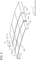
- FIG. 3 is a perspective view of a telescopic cover used for a machine tool, etc., as an example of a machine to which the rubber material recovering method according to some embodiments is applicable.
- the telescopic cover 30 shown in FIG. 3 serves to protect a sliding part (not shown) expandable with movement of a table (not shown) of a machine tool 1B (see FIG. 16 ), which will be described later, from cutting and dust.
- the telescopic cover 30 has a plurality of cover segments, three cover segments 31A, 31B, 31C in the figure. These cover segments 31A, 31B, 31C are stacked so as to be movable relative to each other in the expansion and contraction direction in FIG. 3 .
- Each cover segment 31A, 31B, 31C includes an upper plate 32, and side plates 33, 34 respectively connected to both sides of the upper plate 32 and extending downward.
- inner ends 32a, 33a, 34a of the upper plates 32 and the side plates 33, 34 of the cover segments 31B, 31C are fitted with wipers 36, which are seal members.
- the wiper 36 is shaped to contact outer surfaces of the upper plate 32 and the side plates 33, 34 of the cover segment positioned inside the cover segment fitted with the wiper 36.
- the wiper 36 is made of rubber, for example. The provision of the wiper 36 prevents the ingress of water, oil, or other substances adhering to the surface into the cover segments.
- FIG. 4 is a schematic cross-sectional view of a part of a hydraulic machine as an example of a machine to which the rubber material recovering method according to some embodiments is applicable.
- the hydraulic machine 1C shown in FIG. 4 may be any hydraulic machinery holding a working fluid therein, for example, a hydraulic actuator such as a hydraulic cylinder, or a hydraulic pump.
- the hydraulic machine 1C shown in FIG. 4 has an O-ring 47 provided in a junction between a first housing 41 and a second housing 42, for example.
- An oil holding portion 41a inside the first housing 41 and an oil holding portion 42a inside the second housing 42 are filled with an oil product 45 such as hydraulic oil, fuel, lubricant, grease, or cooling oil.
- the hydraulic machine 1C shown in FIG. 4 may be a pipe or a manifold filled with the oil product 45.
- the oil products 45 as described above contain a base oil and various additives.
- the base oil include mineral oil, synthetic oil, vegetable oil, animal oil.
- the synthetic oil includes hydrocarbon-based oils (poly- ⁇ -olefin, polybutene, synthetic naphthene, etc.) and ester-based oils (aliphatic diester, aromatic ester, etc.).
- the additive include oiliness improvers (fatty acid, alcohol, amine ester, etc.), extreme pressure agents (sulfur-based agent, phosphorus-based agent, etc.), detergent dispersants, antioxidants, corrosion inhibitors, viscosity index improvers, defoaming agents, and thickening agents.
- the rubber material 3 such as the O-ring 25, 47 and the wiper 36 is used for sealing or other applications in various machines 1 (1A to 1C).
- Such rubber material 3 achieves a sealing function through deformation, for instance, upon contact with a metal surface to eliminate a gap from the metal surface.
- the sealing function is reduced as the rubber material 3 is aged and cured.
- the cured rubber material 3 may be replaced with new rubber material by disassembling the machine 1.
- the rubber material 3 is in a portion difficult to disassemble, replacement of the rubber material 3 takes a long time, and the machine 1 cannot be used during replacement.
- the present inventors have intensively studied and consequently found that, as described later in detail, by adding a softener capable of reducing the hardness of the rubber material 3 to the oil product 45 to be used in the machine 1, it is possible to reduce the hardness of the rubber material 3 or suppress the curing of the rubber material 3.
- FIG. 21 is a graph showing the temporal change in hardness of the rubber material 3 as usual, and the temporal change in hardness of the rubber material 3 when the present invention is applied.
- FIG. 22 is a graph showing the temporal change in hardness of the rubber material 3 as usual, and the temporal change in hardness of the rubber material 3 when the present invention is applied.
- the oil product 45 e.g., cutting oil agent used in the machine tool 1B
- the hardness of the rubber material 3 increases over time as shown by the dashed line Lb0 unless the softener is added to the oil product 45 to be replenished.
- the hardness of the rubber material 3 can be reduced back to the value "b1", as shown by the solid line Lb1. Then, by adding the softener again to the oil product 45 able to contact the rubber material 3 at a time point when the use period reaches d2, d3, d4 ..., the hardness of the rubber material 3 can be controlled between the values "b1" and "b2" as shown by the solid line Lb1. Thus, it is possible to extend the lifetime of the rubber material 3.
- the curing of the rubber material 3 due to aging can be suppressed with the oil product 45 containing the softener, as described in the following embodiments.
- the turbo chiller 1A shown in FIG. 1 by adding the softener to refrigeration oil to be used as the oil product 45, it is possible to suppress the curing of the rubber material 3 due to aging, such as the O-ring 25 of the union joint 20, which contacts the refrigeration oil in a circulation circuit of the refrigerant and refrigeration oil. In this case, it is possible to suppress the curing of the rubber material 3 due to aging while using the turbo chiller 1A.
- the softener to be used as the oil product 45 in the later-described machine tool 1B, it is possible to reduce the hardness of the rubber material 3, such as the wiper 36, which contacts the cutting oil agent, or to suppress the curing of the rubber material 3 due to aging. In this case, it is possible to reduce the hardness of the rubber material 3 or to suppress the curing of the rubber material 3 due to aging while using the machine tool 1B.
- the oil product 45 containing the softener e.g., grease or lubricant oil containing the softener as assembly oil for the O-ring 47 when the hydraulic machine 1C is assembled, it is possible to suppress the curing of the rubber material 3 due to aging.
- the oil product 45 is used for lubrication, cooling, power transmission, or sealing of the machine 1 including the rubber material 3, and contains the base oil and the softener for reducing the hardness of the rubber material 3.
- the oil product 45 containing the softener it is possible to reduce the hardness of the rubber material 3 or to suppress the curing of the rubber material 3 while using the machine 1.
- the oil product 45 is grease containing the base oil and the softener.
- the oil product 45 is any of fuel, lubricant oil, a cutting oil agent, refrigeration oil used in a chiller, a pressure transmitting medium, or a heat transfer medium containing the base oil and the softener.
- the machine 1 using any of fuel, lubricant oil, a cutting oil agent, refrigeration oil used in a chiller, a pressure transmitting medium, or a heat transfer medium, it is possible to reduce the hardness of the rubber material or to suppress the curing of the rubber material while using the machine 1.
- the rubber material 3 is a seal member such as the O-ring 25, 47 or the wiper 36.
- SP value is a physical property value defined by the square root of the aggregate energy density and is a value indicating the solubility behavior of a solvent. It is empirically known that the smaller the difference in SP value between two components, the greater the solubility. As for the rubber material 3 and the softener, the smaller the difference between the SP value of the rubber material 3 and the SP value of the softener, the higher the affinity between the rubber material 3 and the softener.
- FIG. 5 is a graph showing the change in hardness of samples when cured chloroprene rubber samples are immersed in an oil product containing a softener for examining the effect of the softener.
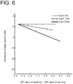
- FIG. 6 is a graph showing the change in hardness of samples when cured nitrile rubber samples are immersed in an oil product containing a softener for examining the effect of the softener.
- FIG 7 is a table showing results of the examination test according to the graphs shown in FIGs. 5 and 6 .
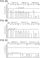
- FIGs. 8A, 8B, and 8C are bar graphs showing the results of the examination test shown in the table of FIG. 7 .
- FIG 8A is a bar graph showing the results of the examination test on the chloroprene rubber samples in FIG. 7 .
- FIG. 8B is a bar graph showing the results of the examination test on the nitrile rubber samples in FIG. 7 .
- FIG. 8C is a bar graph showing the results of the examination test on the fluororubber samples in FIG. 7 .
- the horizontal axis represents a value obtained by subtracting the SP value of the rubber sample from the SP value of the additive
- the vertical axis represents hardness change amount Hs ⁇ of the sample measured by the spring hardness test specified by JIS, i.e., the hardness of the sample after the test when the hardness of the sample before the test is zero.
- chloroprene rubber samples previously immersed in a solvent and forcedly cured were used.
- the samples before the test had a hardness of 73 Hs before the forced curing, and a hardness of 82 Hs after the forced curing.
- nitrile rubber samples previously immersed in a solvent and forcedly cured were used.
- the samples before the test had a hardness of 72 Hs before the forced curing, and a hardness of 79 Hs after the forced curing.
- the immersion time was 24 hours in all tests shown in FIGs. 5 , 6 and 7 .
- the effect of reducing the hardness of the rubber material 3 and the effect of suppressing the curing of the rubber material 3 due to aging vary depending on the period of contact time between the rubber material 3 and the softener.
- FIG. 9 is a table showing results of a test comparing immersion times of 24 and 183 hours.
- FIGs. 10A, 10B, and 10C are bar graphs showing the results of the test shown in the table of FIG. 9 .
- FIG. 10A is a bar graph showing the results of the test on the chloroprene rubber samples in FIG. 9 .
- FIG 10B is a bar graph showing the results of the case where cutting oil A is used as the oil product 45 (medium) in the test on the nitrile rubber samples in FIG. 9 .
- FIG. 10C is a bar graph showing the results of the case where cutting oil B is used as the oil product 45 (medium) in the test on the nitrile rubber samples in FIG. 9 .
- chloroprene rubber samples previously immersed in a solvent and forcedly cured were used.
- the samples before the test had a hardness of 73 Hs before the forced curing, and a hardness of 82 Hs after the forced curing.
- nitrile rubber samples previously immersed in a solvent and forcedly cured were used.
- the samples before the test had a hardness of 72 Hs before the forced curing, and a hardness of 79 Hs after the forced curing.
- an additive (trade name: EPS Engine Power Shield), manufactured by Wako Chemical Co., Ltd., was also used as the softener.
- this additive is denoted as "stopper".
- the additive manufactured by Wako Chemical Co., Ltd. was used as the softener, another additive of the same type may be used as the softener, which provides the same effect as the additive manufactured by Wako Chemical Co., Ltd.
- the test on the chloroprene rubber samples among the tests shown in FIG. 9 was performed with varying the addition amount of the softener: zero (i.e., the softener is not contained), 2.5 wt%, and 5.0 wt%, based on the weight (100%) of the oil product (refrigeration oil) containing the softener.
- the test on the nitrile rubber samples among the tests shown in FIG. 9 was performed with varying the addition amount of the softener: zero (i.e., the softener is not contained), 5.0 wt%, and 10.0 wt%, based on the weight (100%) of the oil product (refrigeration oil) containing the softener.
- suitable conditions were determined as follows, with respect to the difference between the SP value of the rubber material 3 and the SP value of the softener, the addition amount of the softener, and the contact time between the rubber material 3 and the softener.
- the absolute value of the difference between the SP value of the rubber material 3 and the SP value of the softener is preferably 1.7 or less.
- FIG. 11 is a diagram showing ranges of addition amount of the softener and SP value of the softener suitable for recovering the hardness of a cured rubber material 3 and suppressing the aging and curing of the rubber material 3 made of chloroprene rubber (CR).
- the SP value of the rubber material 3 made of chloroprene rubber (CR) was 8.8.
- the oil product 45 containing the softener having a SP value of 8.0 or more and 10.0 or less to the rubber material 3 3
- the hardness of the cured rubber material 3 was reduced to the hardness before use, or the aging and curing of the rubber material 3 was suppressed. That is, in this case, the preferable value of the difference between the SP value of the softener and the SP value of the rubber material 3 is -0.8 or more and 1.2 or less.
- the aging and curing of the rubber material 3 was suppressed by supplying the oil product 45 containing 2.5 wt% or more and 5.0 wt% or less of the softener having a SP value of 8.5 or more and 9.5 or less to the rubber material 3.
- the hardness of the rubber material 3 was reduced to the hardness before use by supplying the oil product 45 containing 10.0 wt% or more and 30.0 wt% or less of the softener having a SP value of 8.0 or more and 10.0 or less to the rubber material 3.
- the contact time between the rubber material 3 and the softener was between 15 hours and 50 hours, i.e., less than one day to about two days, the hardness of the rubber material 3 was not too low or too high.
- the hardness of the rubber material 3 was reduced to the hardness before use by supplying the oil product 45 containing 30.0 wt% or more and 70.0 wt% or less of the softener having a SP value of 8.5 or more and 9.5 or less to the rubber material 3.
- the contact time between the rubber material 3 and the softener was several hours to about 15 hours, the hardness of the rubber material 3 was not too low or too high.
- FIG. 12 is a diagram showing ranges of addition amount of the softener and SP value of the softener suitable for recovering the hardness of a cured rubber material 3 and suppressing the aging and curing of the rubber material 3 made of nitrile rubber (NBR).
- NBR nitrile rubber
- the SP value of the rubber material 3 made of nitrile rubber (NBR) was 9.7.
- NBR nitrile rubber
- the aging and curing of the rubber material 3 was suppressed by supplying the oil product 45 containing 5.0 wt% or more and 10.0 wt% or less of the softener having a SP value of 9.5 or more and 10.5 or less to the rubber material 3.
- NBR nitrile rubber
- the hardness of the rubber material 3 was reduced to the hardness before use by supplying the oil product 45 containing 10.0 wt% or more and 30.0 wt% or less of the softener having a SP value of 8.0 or more and 11.0 or less to the rubber material 3.
- the contact time between the rubber material 3 and the softener was between 15 hours and 50 hours, i.e., less than one day to about two days, the hardness of the rubber material 3 was not too low or too high.
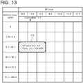
- FIG. 13 is a diagram showing ranges of addition amount of the softener and SP value of the softener suitable for recovering the hardness of a cured rubber material 3 made of fluororubber (FKM).
- the SP value of the rubber material 3 made of fluororubber (FKM) was 7.3.
- FKM fluororubber
- the hardness of the rubber material 3 was reduced to the hardness before use by supplying the oil product 45 containing 5.0 wt% or more and 10.0 wt% or less of the softener having a SP value of 6.0 or more and 9.0 or less to the rubber material 3.
- the contact time between the rubber material 3 and the softener was between 15 hours and 50 hours, i.e., less than one day to about two days, the hardness of the rubber material 3 was not too low or too high.
- the absolute difference between the SP value of the rubber material 3 and the SP value of the softener is preferably 1. 7 or less.
- the rubber material 3 In order to facilitate the transfer of the softener to the rubber material, it is desirable to supply the rubber material 3 with the oil product 45 containing the softener having a SP value the absolute difference of which from the SP value of the rubber material 3 is smaller than the absolute difference from the SP value of the oil product 45.
- the SP value of the oil product 45 is greater than the SP value of the rubber material 3, it is preferable to supply the rubber material 3 with the oil product 45 containing the softener having a SP value less than the SP value of the rubber material 3.
- the SP value of the oil product 45 is less than the SP value of the rubber material 3, it is preferable to supply the rubber material 3 with the oil product 45 containing the softener having a SP value greater than the SP value of the rubber material 3.
- the oil product 45 containing the softener according to the above embodiments can be supplied to the rubber material 3 in a manner as described below.
- the oil product 45 containing the softener according to the above embodiments can be supplied to the rubber material 3 through this communication portion.
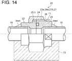
- FIG. 14 is a diagram for describing an example of supply of the oil product 45 containing the softener to the rubber material 3, and shows the same union joint 20 as FIG. 2 .
- the union joint 20 shown in FIGs. 2 and 14 has a gap in a connection portion between a female thread 24a of the union nut 24 and a male thread 23a of the union screw 23.
- This gap continues from the outside of the union joint 20 to the O-ring 25.
- the gap is a communication portion 27 connecting the outside of the machine 1 and the rubber material 3 (see FIG. 14 ).
- the communication portion 27 represented by the gap is labeled with the letter "A" after the reference numeral.
- the oil product 45 containing the softener can reach the O-ring 25 through the gap in the connection portion.
- the pressure in the union joint 20 is controlled by closing a valve (not shown) disposed in a pipe leading to the union joint 20, or if possible, the pressure in the union joint 20 is controlled by temporarily stopping the use of the machine 1.
- a tape-like member such as vinyl tape may be wrapped around the circumference of the union joint 20 to cover the end 28. This prevents the oil product containing the softener from escaping from the end 28 to the outside of the machine 1 (union joint 20). Accordingly, it is possible to suppress an unintended reduction in contact time between the softener and the rubber material 3 due to outflow of the oil product containing the softener to the outside of the machine 1 from the end 28.
- the member covering the end 28 may not have a function to hold the oil product, for instance, by impregnation of the member with the oil product containing the softener like the tape-like member, or may have the function to hold the oil product.
- the member having the function to hold the oil product include porous and deformable members such as a woven fabric, a nonwoven fabric, and a sponge.
- the communication portion 27 connecting the rubber material 3 and the outside of the machine 1 may be formed in the machine 1 including the rubber material 3 so as to allow the rubber material 3 to be supplied with the oil product 45 containing the softener from the outside of the machine 1.
- FIG. 15 is a diagram for describing an example of supply of the oil product 45 containing the softener to the rubber material 3, and shows the case where the through hole is formed in the same union joint 20 as FIGs. 2 and 14 .
- the communication portion 27 represented by the through hole is labeled with the letter "B" after the reference numeral.
- the oil product 45 containing the softener can reach the O-ring 25 through the through hole.
- the end 29 may be covered as with the embodiment shown in FIG. 14 .
- a pipe 77 may be connected to the end 29, and the oil product 45 containing the softener may be supplied to the O-ring 25 via the pipe 77 from a tank 75 disposed outside the machine 1 using a pump 73.
- the pipe 77 may be removed from the end 29, and the end 29 may be covered as with the embodiment shown in FIG. 14 .
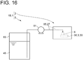
- FIG. 16 is a simplified overall configuration diagram of a machine tool 1B as an example of the machine 1 including a supply unit for supplying the oil product 45 containing the softener to the rubber material 3.
- the machine tool 1B shown in FIG. 16 includes a machining unit 2, a supply unit 5 for supplying cutting oil to the machining unit 2, and the telescopic cover 30 shown in FIG. 3 .
- the machining unit 2 of the machine tool 1B shown in FIG. 16 can machine, e.g., cut, a workpiece 6.
- the supply unit 5 has a supply device (supply pump) 81 for supplying cutting oil to the machining unit 2, more specifically, to a portion of the workpiece 6 to be machined by the machining unit 2, and a tank 83 of the cutting oil.
- the supply unit 5 can supply the cutting oil (oil product 45) in the tank 83 to the workpiece 6 via a supply pipe 85 using the supply pump 81.
- the oil product 45 supplied to the workpiece 6 from the supply unit 5 also contacts the telescopic cover 30 described above. Further, the oil product 45 contacts the wiper 36 with the relative movement of the cover segments 31A, 31B, 31C of the telescopic cover 30 in the expansion and contraction direction in FIG. 3 .
- the supply unit 5 supplies the oil product 45 containing the softener to the rubber material 3 (wiper 36). In other words, the supply unit 5 supplies the oil product containing the softener so that the oil product contacts the rubber material 3.
- the machine tool 1B may be used with the oil product 45 (cutting oil) containing no softener to prevent the hardness of the wiper 36 from being reduced more than necessary.
- the supply unit 5 includes the supply device 81 for supplying the oil product 45 containing the softener and the supply pipe 85 serving as a channel introducing the oil product 45 containing the softener supplied from the supply device 81 to the rubber material 3.
- FIG. 17 is a simplified overall configuration diagram of a spraying device 1D as an example of the machine 1 including the supply unit for supplying the oil product 45.
- the spraying device 1D shown in FIG. 17 includes a spray nozzle 7 and a supply unit 5A for supplying the oil product 45 to the spray nozzle 7.
- the spraying device 1D shown in FIG. 17 can spray the oil product 45 from the spray nozzle 7 to a spray target 87.
- the supply unit 5A has a supply device (supply pump) 81 for supplying the oil product 45 to the spray nozzle 7 and a tank 83 for the oil product 45.
- the supply unit 5A can supply the oil product 45 in the tank 83 to the spray nozzle 7 via a supply pipe 85 using the supply pump 81.
- the rubber material 3 is used for sealing of components such as the spray nozzle 7 and a joint of the supply pipe 85. With use of the spraying device 1D, a plasticizer contained in the rubber material 3 may elute into the oil product 45, resulting in the curing of the rubber material 3.
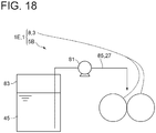
- FIG. 18 is a simplified overall configuration diagram of a machine 1E including the supply unit for supplying the oil product 45 containing the softener.
- the machine 1E shown in FIG. 18 includes a plurality of rubber rollers 8 in contact with each other and a supply unit 5B for supplying the oil product 45 to the rubber rollers 8.
- the machine 1E shown in FIG. 18 may be a printing machine.
- the oil product 45 used in this machine 1E may be printing ink, for example.
- FIG. 18 depicts two rubber rollers 8 in contact with each other, the number of the rubber rollers 8 in contact with each other may be three or more.
- the supply unit 5B has a supply device (supply pump) 81 for supplying the oil product 45 to the rubber rollers 8 in contact with each other and a tank 83 for the oil product 45.
- the supply unit 5B can supply the oil product 45 in the tank 83 to the contact portion between the rubber rollers 8 via a supply pipe 85 using the supply pump 81.
- a plasticizer contained in the rubber material 3 of the rubber rollers 8 may elute into the oil product 45, resulting in the curing of the rubber material 3.
- the oil product 45 with the softener can contact the rubber material 3 of the rubber rollers 8.
- the oil product 45 containing the softener can contact and permeate into the entire rubber material 3 covering the outer periphery of the rubber rollers 8.
- the oil product 45 may be supplied to the rubber rollers 8 using the spray nozzle 7 shown in FIG. 17 .
- the interior of the hydraulic machine 1C i.e. the oil holding portions 41a, 42a are filled with the oil product 45. That is, the oil holding portions 41a, 42a of the hydraulic machine 1C shown in FIG. 4 are a filled portion 43 filled with the oil product 45.
- the softener can be supplied to the O-ring 47 of the rubber material 3. Accordingly, in the hydraulic machine 1C shown in FIG. 4 , the supply unit 5 for supplying the oil product 45 containing the softener to the rubber material 3 includes the filled portion 43 filled with the oil product 45 containing the softener so that the oil product containing the softener contacts the rubber material 3.
- the hydraulic machine 1C shown in FIG. 4 allows the oil product 45 containing the softener to stably contact the rubber material 3.
- the oil product 45 may or may not flow inside the hydraulic machine 1C.
- the interior of the hydraulic machine 1C may be filled with the oil product 45 containing no softener to prevent the hardness of the O-ring 47 from being reduced more than necessary.
- each machine 1 has the communication portion 27 connecting the outside of the machine 1 and the rubber material 3.
- the gap in the connection portion between the female thread 24a of the union nut 24 and the male thread 23 a of the union screw 23 is the communication portion 27A.
- the through hole formed in the union joint 20 is the communication portion 27B.
- the supply pipe 85 is the communication portion 27.
- the machine 1 is configured to able to supply the oil product 45 containing the softener to the rubber material 3 by supplying the oil product 45 from a first end of the communication portion 27 to a second end of the communication portion 27.
- the machine 1 when the oil product 45 is supplied through the communication portion 27, the machine 1 is operated so as to change a region of the rubber material 3 facing the second end of the communication portion 27.
- the machine tool 1B is operated so that the cover segments 31A, 31B, 31C of the telescopic cover 30 move relative to each other in the expansion and contraction direction while the oil product 45 is supplied by the supply unit 5.
- the second end of the communication portion 27, i.e., the outlet-side end of the supply pipe 85, and the wiper 36 changes, the region of the rubber material 3 facing the second end of the communication portion 27 changes.
- the machine 1E is operated so that the rubber rollers 8 in contact with each other rotate while the oil product 45 is supplied to the rubber rollers 8 by the supply unit 5B.
- the outer peripheral surface of the rubber rollers 8 moves relative to the second end of the communication portion 27, i.e., the outlet-side end of the supply pipe 85, the region of the rubber material 3 facing the second end of the communication portion 27 changes.
- the oil product 45 containing the softener can be supplied to a wide region of the rubber material 3, it is possible to reduce the hardness of the rubber material 3 or to suppress the curing of the rubber material 3 in a wide region of the rubber material 3.
- the machine 1E includes the rubber rollers 8 in contact with each other.
- the oil product 45 is supplied to the contact portion of the rubber rollers from the second end of the communication portion 27.
- the communication portion 27 may be formed prior to supplying the oil product 45 through the communication portion 27, and the first end thereof may be covered after completion of supply of the oil product 45.
- the communication portion 27A is formed prior to supplying the oil product 45 through the communication portion 27A. Then, as described above, in the embodiment shown in FIG. 14 , after the oil product 45 containing the softener is supplied, the first end of the communication portion 27A, i.e., the end 28, may be covered.
- the communication portion 27B is formed prior to supplying the oil product 45 through the communication portion 27B. Then, as described above, in the embodiment shown in FIG. 15 , after the oil product 45 containing the softener is supplied, the first end of the communication portion 27B, i.e., the end 28, may be covered.
- the oil product 45 containing the softener can be supplied to the rubber material 3 through the communication portion 27. Further, according to some embodiments, since the first end of the communication portion 27 is covered after completion of supply of the oil product 45 containing the softener, as described above, it is possible to prevent the oil product 45 containing the softener from flowing out from the end. Thus, it is possible to suppress an unintended reduction in contact time between the softener and the rubber material 3 due to outflow of the oil product 45 containing the softener from the end.
- the first end of the communication portion 27 is connected to the supply device (supply unit 5) storing the oil product 45 via a channel.
- the first end of the communication portion 27, i.e., the end 29, is connected to the tank 75 of the supply unit 5 storing the oil product 45 via the pipe 77 which is the channel.
- the oil product 45 is supplied to the rubber material 3 for lubrication, cooling, power transmission, or sealing in the machine 1 as described above.
- the oil product 45 is grease containing the base oil and the softener.
- the oil product 45 is any of fuel, lubricant oil, a cutting oil agent, refrigeration oil used in a chiller, a pressure transmitting medium, or a heat transfer medium containing the base oil and the softener.
- the method for recovering the rubber material 3 includes a supplying step S10 of supplying the rubber material 3 with the oil product 45 containing the softener having a SP value the absolute difference of which from the SP value of the rubber material 3 is 1.7 or less.
- FIG. 19 is a flowchart showing the process of the method for recovering the rubber material 3 according to some embodiments.
- the oil product 45 containing the softener is supplied to the rubber material 3 in accordance with various embodiments described above.
- the rubber material recovery method includes an adding step S5 of adding the softener for reducing the hardness of the rubber material 3 to the oil product 45 used for lubrication, cooling, power transmission, or sealing of the machine including the rubber material 3.
- the softener is added to the cutting oil by supplying the softener to the tank 83 in FIG. 16 so as to meet a SP value and a concentration in the range 111 in FIG. 13 , the range 122 in FIG. 11 , or the range 132 in FIG. 12 . Then, in the supplying step S10 shown in FIG. 19 , the cutting oil containing the softener is supplied to the wiper 36.
- FIG. 20 is a flowchart showing the process of the method for recovering the rubber material 3 according to some embodiments.
- the present invention is not limited to the embodiments described above, but includes modifications to the embodiments described above, and embodiments composed of combinations of those embodiments.
- the softeners exemplified in the above description is merely examples of the softener to which the present invention is applicable and do not exclude any other softener.
Landscapes
- Chemical & Material Sciences (AREA)
- Chemical Kinetics & Catalysis (AREA)
- Organic Chemistry (AREA)
- Health & Medical Sciences (AREA)
- Medicinal Chemistry (AREA)
- Polymers & Plastics (AREA)
- Life Sciences & Earth Sciences (AREA)
- Sustainable Development (AREA)
- General Chemical & Material Sciences (AREA)
- Oil, Petroleum & Natural Gas (AREA)
- Compositions Of Macromolecular Compounds (AREA)
- Gasket Seals (AREA)
- Sealing Material Composition (AREA)
- Lubricants (AREA)
Abstract
Description
- The present disclosure relates to a rubber material recovery method and an oil product.
- Rubber material is used in various machines for sealing and other applications. Such rubber material achieves a sealing function through deformation, for instance, upon contact with a metal surface to eliminate a gap from the metal surface.
- However, in such rubber material, the sealing function is reduced as the rubber material is aged and cured.
- For example,
Patent Document 1 discloses that a rubber roller of a printing machine to be reclaimed is kneaded under mechanical pressure while supplying a rubber roller reclaiming agent to the surface of the rubber roller to reduce the hardness of rubber of the rubber roller (see Patent Document 1). - Patent Document 1:
JP2017-74682A -
Patent Document 1 discloses the composition of the rubber roller reclaiming agent, but does not specify the material of rubber of the rubber roller to which the rubber roller reclaiming agent is applied. Accordingly, it is unknown from the disclosures ofPatent Document 1 what composition of the rubber roller reclaiming agent is effective for which material of rubber. - In view of the above, an object of at least one embodiment of the present invention is to provide a suitable rubber material recovery method according to the material of the rubber material.
- (1) A rubber material recovery method according to at least one embodiment of the present invention comprises a step of supplying an oil product containing a softener to a rubber material, wherein an absolute difference between a solubility parameter of the softener and a solubility parameter of the rubber material is 1.7 or less.
With the above method (1), since the rubber material is supplied with the oil product containing the softener having a SP value the absolute difference of which from the SP value of the rubber material is 1.7 or less, it is possible to effectively reduce the hardness of the rubber material or to effectively suppress the curing of the rubber material. - (2) In some embodiments, in the above method (1), the step of supplying the oil product includes supplying the oil product containing the softener having a solubility parameter of 6.0 or more and 9.0 or less to the rubber material made of fluororubber.
As a result of intensive studies by the present inventors, it was found that when the oil product containing the above softener is supplied to the rubber material made of fluororubber, the hardness of the cured rubber material is reduced to the hardness before use.
Thus, with the above method (2), it is possible to reduce the hardness of the cured rubber material made of fluororubber to the hardness before use. - (3) In some embodiments, in the above method (2), the step of supplying the oil product includes supplying the oil product containing 5.0 wt% or more and 10.0 wt% or less of the softener to the rubber material made of fluororubber.
As a result of intensive studies by the present inventors, it was found that when the oil product containing the above proportion of the softener is supplied to the rubber material made of fluororubber for a period, e.g., about 1 day, the hardness of the cured rubber material is reduced to the hardness before use.
Thus, with the above method (3), it is possible to reduce the hardness of the cured rubber material made of fluororubber to the hardness before use in a relatively short time. - (4) In some embodiments, in the above method (1), the step of supplying the oil product includes supplying the oil product containing the softener having a solubility parameter of 8.0 or more and 10.0 or less to the rubber material made of chloroprene rubber.
As a result of intensive studies by the present inventors, it was found that when the oil product containing the above softener is supplied to the rubber material made of chloroprene rubber, the hardness of the cured rubber material is reduced to the hardness before use, or the aging and curing of the rubber material is suppressed.
Thus, with the above method (4), it is possible to reduce the hardness of the cured rubber material made of chloroprene rubber to the hardness before use, or to suppress the aging and curing of the rubber material. - (5) In some embodiments, in the above method (4), the step of supplying the oil product includes supplying the oil product containing 2.5 wt% or more and 5.0 wt% or less of the softener having a solubility parameter of 8.5 or more and 9.5 or less to the rubber material made of chloroprene rubber.
As a result of intensive studies by the present inventors, it was found that when the oil product containing the above proportion of the softener is supplied to the rubber material made of chloroprene rubber, the curing of the rubber material is suppressed.
Thus, with the above method (3), it is possible to suppress the curing of the rubber material made of chloroprene rubber over a relatively long period of time. - (6) In some embodiments, in the above method (4), the step of supplying the oil product includes supplying the oil product containing 10.0 wt% or more and 30.0 wt% or less of the softener having a solubility parameter of 8.0 or more and 10.0 or less to the rubber material made of chloroprene rubber.
As a result of intensive studies by the present inventors, it was found that when the oil product containing the above proportion of the softener is supplied to the rubber material made of chloroprene rubber for a period, e.g., about 1 day, the hardness of the cured rubber material is reduced to the hardness before use.
Thus, with the above method (6), it is possible to reduce the hardness of the rubber material made of chloroprene rubber to the hardness before use in a relatively short time. - (7) In some embodiments, in the above method (4), the step of supplying the oil product includes supplying the oil product containing 30.0 wt% or more and 70.0 wt% or less of the softener having a solubility parameter of 8.5 or more and 9.5 or less to the rubber material made of chloroprene rubber.
As a result of intensive studies by the present inventors, it was found that when the oil product containing the above proportion of the softener is supplied to the rubber material made of chloroprene rubber for a period, e.g., a dozen hours, the hardness of the cured rubber material is reduced to the hardness before use.
Thus, with the above method (7), it is possible to reduce the hardness of the cured rubber material made of chloroprene rubber to the hardness before use in a relatively short time. - (8) In some embodiments, in the above method (1), the step of supplying the oil product includes supplying the oil product containing the softener having a solubility parameter of 8.0 or more and 11.0 or less to the rubber material made of nitrile rubber.
As a result of intensive studies by the present inventors, it was found that when the oil product containing the above softener is supplied to the rubber material made of nitrile rubber, the hardness of the cured rubber material is reduced to the hardness before use, or the aging and curing of the rubber material is suppressed.
Thus, with the above method (8), it is possible to reduce the hardness of the cured rubber material made of nitrile rubber to the hardness before use, or to suppress the aging and curing of the rubber material. - (9) In some embodiments, in the above method (8), the step of supplying the oil product includes supplying the oil product containing 5.0 wt% or more and 10.0 wt% or less of the softener having a solubility parameter of 9.5 or more and 10.5 or less to the rubber material made of nitrile rubber.
As a result of intensive studies by the present inventors, it was found that when the oil product containing the above proportion of the softener is supplied to the rubber material made of nitrile rubber, the curing of the rubber material is suppressed.
Thus, with the above method (9), it is possible to suppress the curing of the rubber material made of nitrile rubber over a relatively long period of time. - (10) In some embodiments, in the above method (8), the step of supplying the oil product includes supplying the oil product containing 10.0 wt% or more and 30.0 wt% or less of the softener having a solubility parameter of 8.0 or more and 11.0 or less to the rubber material made of nitrile rubber.
As a result of intensive studies by the present inventors, it was found that when the oil product containing the above proportion of the softener is supplied to the rubber material made of nitrile rubber for a period, e.g., about 1 day, the hardness of the cured rubber material is reduced to the hardness before use.
Thus, with the above method (10), it is possible to reduce the hardness of the cured rubber material made of nitrile rubber to the hardness before use in a relatively short time. - (11) In some embodiments, in any one of the above methods (1) to (10), the step of supplying the oil product includes supplying the oil product containing the softener having the solubility parameter the absolute difference of which from the solubility parameter of the rubber material is smaller than an absolute difference between the solubility parameter of the softener and a solubility parameter of the oil product.
With the above method (11), since the softener easily moves to the rubber material, it is possible to effectively reduce the hardness of the rubber material or to effectively suppress the curing of the rubber material. - (12) An oil product according to at least one embodiment of the present invention is used for reducing a hardness of a rubber material, and contains a softener, wherein an absolute difference between a solubility parameter of the softener and a solubility parameter of the rubber material is 1.7 or less.
With the above configuration (12), since the oil product contains the softener having a SP value the absolute difference of which from the SP value of the rubber material is 1.7 or less, using this oil product, it is possible to effectively reduce the hardness of the rubber material or to effectively suppress the curing of the rubber material. - (13) In some embodiments, in the above configuration (12), when the rubber material is made of fluororubber, the solubility parameter of the softener contained in the oil product is 6.0 or more and 9.0 or less.
As described above, as a result of intensive studies by the present inventors, it was found that when the oil product containing the above softener is supplied to the rubber material made of fluororubber, the hardness of the cured rubber material is reduced to the hardness before use.
Thus, with the above configuration (13), using this oil product, it is possible to reduce the hardness of the cured rubber material made of fluororubber to the hardness before use. - (14) In some embodiments, in the above configuration (12), when the rubber material is made of chloroprene rubber, the solubility parameter of the softener contained in the oil product is 8.0 or more and 10.0 or less.
As described above, as a result of intensive studies by the present inventors, it was found that when the oil product containing the above softener is supplied to the rubber material made of chloroprene rubber, the hardness of the cured rubber material is reduced to the hardness before use, or the aging and curing of the rubber material is suppressed.
Thus, with the above configuration (14), using this oil product, it is possible to reduce the hardness of the cured rubber material made of chloroprene rubber to the hardness before use, or to suppress the aging and curing of the rubber material. - (15) In some embodiments, in the above configuration (12), when the rubber material is made of nitrile chloroprene rubber, the solubility parameter of the softener contained in the oil product is 8.0 or more and 11.0 or less.
As described above, as a result of intensive studies by the present inventors, it was found that when the oil product containing the above softener is supplied to the rubber material made of nitrile rubber, the hardness of the cured rubber material is reduced to the hardness before use, or the aging and curing of the rubber material is suppressed.
Thus, with the above configuration (15), using this oil product, it is possible to reduce the hardness of the cured rubber material made of nitrile rubber to the hardness before use, or to suppress the aging and curing of the rubber material. - (16) In some embodiments, in any one of the above configurations (12) to (15), the oil product is to be supplied to a rubber material used for lubrication, cooling, power transmission, or sealing of a machine.
In the above configuration (16), the oil product is used for lubrication, cooling, power transmission, or sealing of a machine including the rubber material, and contains the softener. Accordingly, by using the oil product with the above configuration (16), it is possible to reduce the hardness of the rubber material or to suppress the curing of the rubber material while using the machine. - (17) In some embodiments, in any one of the above configurations (12) to (15), the oil product is grease containing a base oil and the softener.
With the above configuration (17), in a machine using grease, it is possible to reduce the hardness of the rubber material or to suppress the curing of the rubber material while using the machine. - (18) In some embodiments, in any one of the above configurations (12) to (15), the oil product is any of fuel, lubricant oil, a cutting oil agent, refrigeration oil used in a chiller, a pressure transmitting medium, or a heat transfer medium containing a base oil and the softener.
- With the above configuration (18), in a machine using any of fuel, lubricant oil, a cutting oil agent, refrigeration oil used in a chiller, a pressure transmitting medium, or a heat transfer medium, it is possible to reduce the hardness of the rubber material or to suppress the curing of the rubber material while using the machine.
- According to at least one embodiment of the present invention, it is possible to provide a suitable rubber material recovery method according to the material of the rubber material.
-
-
FIG. 1 is an overall system diagram of a turbo chiller as an example of a machine to which the rubber material recovering method according to some embodiments is applicable. -
FIG. 2 is a diagram showing an example of the structure of a union joint. -
FIG. 3 is a perspective view of a telescopic cover used for a machine tool, etc., as an example of a machine to which the rubber material recovering method according to some embodiments is applicable. -
FIG. 4 is a schematic cross-sectional view of a part of a hydraulic machine as an example of a machine to which the rubber material recovering method according to some embodiments is applicable. -
FIG. 5 is a graph showing the change in hardness of samples when cured chloroprene rubber samples are immersed in an oil product containing a softener for examining the effect of the softener. -
FIG. 6 is a graph showing the change in hardness of samples when cured nitrile rubber samples are immersed in an oil product containing a softener for examining the effect of the softener. -
FIG 7 is a table showing results of the examination test according to the graphs shown inFIGs. 5 and6 . -
FIG. 8A is a bar graph showing the results of the examination test shown in the table ofFIG. 7 . -
FIG. 8B is a bar graph showing the results of the examination test shown in the table ofFIG. 7 . -
FIG. 8C is a bar graph showing the results of the examination test shown in the table ofFIG. 7 . -
FIG. 9 is a table showing results of a test comparing immersion times of 24 and 183 hours. -
FIG. 10A is a bar graph showing the results of the test shown in the table ofFIG. 9 . -
FIG. 10B is a bar graph showing the results of the test shown in the table ofFIG. 9 . -
FIG. 10C is a bar graph showing the results of the test shown in the table ofFIG. 9 . -
FIG. 11 is a diagram showing ranges of addition amount of a softener and SP value of the softener suitable for recovering the hardness of a cured rubber material and suppressing the aging and curing of the rubber material made of chloroprene rubber (CR). -
FIG. 12 is a diagram showing ranges of addition amount of a softener and SP value of the softener suitable for recovering the hardness of a cured rubber material and suppressing the aging and curing of the rubber material made of nitrile rubber (NBR). -
FIG. 13 is a diagram showing ranges of addition amount of a softener and SP value of the softener suitable for recovering the hardness of a cured rubber material made of fluororubber (FKM). -
FIG. 14 is a diagram for describing an example of supply of an oil product containing a softener to a rubber material. -
FIG. 15 is a diagram for describing an example of supply of an oil product containing a softener to a rubber material. -
FIG. 16 is a simplified overall configuration diagram of a machine tool as an example of a machine including a supply unit for supplying an oil product containing a softener to a rubber material. -
FIG. 17 is a simplified overall configuration diagram of a spraying device as an example of a machine including a supply unit for supplying an oil product. -
FIG. 18 is a simplified overall configuration diagram of a machine including a supply unit for supplying an oil product containing a softener. -
FIG. 19 is a flowchart showing the process of the method for recovering a rubber material according to some embodiments. -
FIG. 20 is a flowchart showing the process of the method for recovering a rubber material according to some embodiments. -
FIG. 21 is a graph showing the temporal change in hardness of a rubber material as usual, and the temporal change in hardness of a rubber material when the present invention is applied. -
FIG. 22 is a graph showing the temporal change in hardness of a rubber material as usual, and the temporal change in hardness of a rubber material when the present invention is applied. - Embodiments of the present invention will now be described in detail with reference to the accompanying drawings. It is intended, however, that unless particularly identified, dimensions, materials, shapes, relative positions and the like of components described in the embodiments shall be interpreted as illustrative only and not intended to limit the scope of the present invention.
- For instance, an expression of relative or absolute arrangement such as "in a direction", "along a direction", "parallel", "orthogonal", "centered", "concentric" and "coaxial" shall not be construed as indicating only the arrangement in a strict literal sense, but also includes a state where the arrangement is relatively displaced by a tolerance, or by an angle or a distance whereby it is possible to achieve the same function.
- For instance, an expression of an equal state such as "same" "equal" and "uniform" shall not be construed as indicating only the state in which the feature is strictly equal, but also includes a state in which there is a tolerance or a difference that can still achieve the same function.
- Further, for instance, an expression of a shape such as a rectangular shape or a cylindrical shape shall not be construed as only the geometrically strict shape, but also includes a shape with unevenness or chamfered corners within the range in which the same effect can be achieved.
- On the other hand, an expression such as "comprise", "include", "have", "contain" and "constitute" are not intended to be exclusive of other components.
-
FIG. 1 is an overall system diagram of a turbo chiller as an example of a machine to which the rubber material recovering method according to some embodiments is applicable. - The
turbo chiller 1A is a refrigeration device using a turbo compressor such as a centrifugal compressor, which is widely used for large-scale factory air conditioning, district heating and cooling, and other applications. - The
turbo chiller 1A includes acentrifugal compressor 10 for compressing a refrigerant, acondenser 11 for cooling the compressed refrigerant, a first expansion valve (pressure reducer) 12 for reducing the pressure of the refrigerant from thecondenser 11, an economizer (gas-liquid separator) 14 for separating the refrigerant from thefirst expansion valve 12 into a gas phase and a liquid phase, a second expansion valve (pressure reducer) 13 for reducing the pressure of the liquid phase from theeconomizer 14, and anevaporator 15 for evaporating the refrigerant from thesecond expansion valve 13. In theturbo chiller 1A shown inFIG. 1 , acondenser safety valve 17 and anevaporator safety valve 18 are connected to arefrigerant circuit pipe 16 via union joints 20, for example. Theturbo chiller 1A is filled with refrigeration oil circulating inside theturbo chiller 1A together with the refrigerant. -
FIG. 2 is a diagram showing an example of the structure of the union joint 20. The union joint 20 includes, for example, aunion flange 22 attached to onerefrigerant circuit pipe 16, aunion screw 23 attached to anotherrefrigerant circuit pipe 16, and aunion nut 24 connecting theunion flange 22 and theunion screw 23. The contact portion between theunion flange 22 and theunion screw 23 is fitted with an O-ring 25 to prevent leakage of the internal fluid. The onerefrigerant circuit pipe 16 and theunion flange 22 may be connected by welding, and the otherrefrigerant circuit pipe 16 and theunion screw 23 may be connected by welding, for instance. -
FIG. 3 is a perspective view of a telescopic cover used for a machine tool, etc., as an example of a machine to which the rubber material recovering method according to some embodiments is applicable. Thetelescopic cover 30 shown inFIG. 3 serves to protect a sliding part (not shown) expandable with movement of a table (not shown) of amachine tool 1B (seeFIG. 16 ), which will be described later, from cutting and dust. As shown inFIG. 3 , thetelescopic cover 30 has a plurality of cover segments, threecover segments segments FIG. 3 . - Each
cover segment upper plate 32, andside plates upper plate 32 and extending downward. For instance,inner ends upper plates 32 and theside plates cover segments upper plate 32 and theside plates -
FIG. 4 is a schematic cross-sectional view of a part of a hydraulic machine as an example of a machine to which the rubber material recovering method according to some embodiments is applicable. Thehydraulic machine 1C shown inFIG. 4 may be any hydraulic machinery holding a working fluid therein, for example, a hydraulic actuator such as a hydraulic cylinder, or a hydraulic pump. - The
hydraulic machine 1C shown inFIG. 4 has an O-ring 47 provided in a junction between afirst housing 41 and asecond housing 42, for example. An oil holding portion 41a inside thefirst housing 41 and an oil holding portion 42a inside thesecond housing 42 are filled with anoil product 45 such as hydraulic oil, fuel, lubricant, grease, or cooling oil. Thehydraulic machine 1C shown inFIG. 4 may be a pipe or a manifold filled with theoil product 45. - Generally, the
oil products 45 as described above contain a base oil and various additives. Examples of the base oil include mineral oil, synthetic oil, vegetable oil, animal oil. The synthetic oil includes hydrocarbon-based oils (poly-α-olefin, polybutene, synthetic naphthene, etc.) and ester-based oils (aliphatic diester, aromatic ester, etc.). Examples of the additive include oiliness improvers (fatty acid, alcohol, amine ester, etc.), extreme pressure agents (sulfur-based agent, phosphorus-based agent, etc.), detergent dispersants, antioxidants, corrosion inhibitors, viscosity index improvers, defoaming agents, and thickening agents. - As described above, the
rubber material 3 such as the O-ring 25, 47 and the wiper 36 is used for sealing or other applications in various machines 1 (1A to 1C).Such rubber material 3 achieves a sealing function through deformation, for instance, upon contact with a metal surface to eliminate a gap from the metal surface. - However, in
such rubber material 3, the sealing function is reduced as therubber material 3 is aged and cured. The curedrubber material 3 may be replaced with new rubber material by disassembling themachine 1. However, if therubber material 3 is in a portion difficult to disassemble, replacement of therubber material 3 takes a long time, and themachine 1 cannot be used during replacement. Even if therubber material 3 is in a portion easy to disassemble and assemble, when themachine 1, such as theturbo chiller 1A, is filled with a working medium, it may be necessary to remove the working medium out of the machine during disassembly and return it to the machine after assembly. Therefore, it is desired to reduce the hardness of therubber material 3 without disassembling and assembling themachine 1, and it is more preferable to reduce the hardness of therubber material 3 while using themachine 1. - The present inventors have intensively studied and consequently found that, as described later in detail, by adding a softener capable of reducing the hardness of the
rubber material 3 to theoil product 45 to be used in themachine 1, it is possible to reduce the hardness of therubber material 3 or suppress the curing of therubber material 3. - With reference to
FIGs. 21 and 22 , an overview of the present invention will be described. -
FIG. 21 is a graph showing the temporal change in hardness of therubber material 3 as usual, and the temporal change in hardness of therubber material 3 when the present invention is applied. - For example, consider the case where the
rubber material 3 is used for sealing of themachine 1, and a new oil product cannot be brought into contact with therubber material 3 unless themachine 1 is stopped and at least a part of themachine 1 is disassembled. In this case, if an oil product used in assembling therubber material 3 contains no softener, a plasticizer (softener) in therubber material 3 assembled to themachine 1 is gradually eliminated from therubber material 3 over time, which leads to an increase in hardness of therubber material 3. In other words, for example as shown by the dashed line La0 inFIG. 21 , where "a" is the hardness of therubber material 3 in new condition, the hardness of therubber material 3 increases over time. Then, when the hardness of therubber material 3 exceeds the value "c", problems such as leakage begin to occur. - To solve the problems, it is conceivable to previously add the softener to the
oil product 45 to be used in assembly. This enables, for example as shown by the solid line La1 inFIG. 21 , the hardness of therubber material 3 to decrease from the value "a" to the value "b" at the start of use of therubber material 3. The hardness of therubber material 3 then increases over time, but the curing speed is lower than the case where the softener is not added. Therefore, it is possible to extend the lifetime of therubber material 3. -
FIG. 22 is a graph showing the temporal change in hardness of therubber material 3 as usual, and the temporal change in hardness of therubber material 3 when the present invention is applied. - For example, consider the case where the
rubber material 3 is used for sealing of themachine 1, and a new oil product can be brought into contact with therubber material 3 regardless of stopping themachine 1. In this case, by adding the softener to the oil product able to contact therubber material 3 at the start of use of themachine 1, for example as shown by the dashed line Lb0 and the solid line Lb1 inFIG. 22 , the hardness of therubber material 3 decreases from the value "a" to the value "b1" at the start of use of therubber material 3. For example as in the case of amachine tool 1B described later, if the oil product 45 (e.g., cutting oil agent used in themachine tool 1B) able to contact therubber material 3 needs to be replenished in accordance with the use of themachine 1, the hardness of therubber material 3 increases over time as shown by the dashed line Lb0 unless the softener is added to theoil product 45 to be replenished. - Therefore, by adding the softener again to the
oil product 45 able to contact therubber material 3 at a time point when the period of use of themachine 1 reaches d1, the hardness of therubber material 3 can be reduced back to the value "b1", as shown by the solid line Lb1. Then, by adding the softener again to theoil product 45 able to contact therubber material 3 at a time point when the use period reaches d2, d3, d4 ..., the hardness of therubber material 3 can be controlled between the values "b1" and "b2" as shown by the solid line Lb1. Thus, it is possible to extend the lifetime of therubber material 3. - Even if the
oil product 45 able to contact therubber material 3 needs to be replenished in accordance with the use of themachine 1, by controlling the concentration of the softener in theoil product 45 within a certain range, it is possible to keep the hardness of therubber material 3 at the initial value "a" as shown by the solid line Lb2 inFIG. 22 . - In addition, even in the case where the oil product able to contact the
rubber material 3 does not need to be frequently replenished since theoil product 45 circulates and is reused, by previously adding the softener to theoil product 45, it is possible to keep the hardness of therubber material 3 at the initial value "a" as shown by the solid line Lb2 inFIG. 22 . - Based on the aforementioned overview of the present invention, the curing of the
rubber material 3 due to aging can be suppressed with theoil product 45 containing the softener, as described in the following embodiments. - For example, in the case of the
turbo chiller 1A shown inFIG. 1 , by adding the softener to refrigeration oil to be used as theoil product 45, it is possible to suppress the curing of therubber material 3 due to aging, such as the O-ring 25 of the union joint 20, which contacts the refrigeration oil in a circulation circuit of the refrigerant and refrigeration oil. In this case, it is possible to suppress the curing of therubber material 3 due to aging while using theturbo chiller 1A. - For example, in the case of the
telescopic cover 30 shown inFIG. 3 , by adding the softener to a cutting oil agent to be used as theoil product 45 in the later-describedmachine tool 1B, it is possible to reduce the hardness of therubber material 3, such as the wiper 36, which contacts the cutting oil agent, or to suppress the curing of therubber material 3 due to aging. In this case, it is possible to reduce the hardness of therubber material 3 or to suppress the curing of therubber material 3 due to aging while using themachine tool 1B. - For example, in the case of the
hydraulic machine 1C shown inFIG. 4 , by adding the softener to theoil product 45 filling the machine, it is possible to reduce the hardness of therubber material 3, such as the O-ring 47, which contacts theoil product 45, or to suppress the curing of therubber material 3 due to aging. In this case, it is possible to reduce the hardness of therubber material 3 or to suppress the curing of therubber material 3 due to aging while using thehydraulic machine 1C. - Further, for example, in the case of the
hydraulic machine 1C shown inFIG. 4 , by using theoil product 45 containing the softener, e.g., grease or lubricant oil containing the softener as assembly oil for the O-ring 47 when thehydraulic machine 1C is assembled, it is possible to suppress the curing of therubber material 3 due to aging. - As described above, the
oil product 45 according to some embodiments is used for lubrication, cooling, power transmission, or sealing of themachine 1 including therubber material 3, and contains the base oil and the softener for reducing the hardness of therubber material 3. - Accordingly, by using the
oil product 45 containing the softener, it is possible to reduce the hardness of therubber material 3 or to suppress the curing of therubber material 3 while using themachine 1. - In some embodiments, the
oil product 45 is grease containing the base oil and the softener. - Thus, in the
machine 1 using grease, it is possible to reduce the hardness of therubber material 3 or to suppress the curing of therubber material 3 while using themachine 1. - In some embodiments, the
oil product 45 is any of fuel, lubricant oil, a cutting oil agent, refrigeration oil used in a chiller, a pressure transmitting medium, or a heat transfer medium containing the base oil and the softener. - Thus, in the
machine 1 using any of fuel, lubricant oil, a cutting oil agent, refrigeration oil used in a chiller, a pressure transmitting medium, or a heat transfer medium, it is possible to reduce the hardness of the rubber material or to suppress the curing of the rubber material while using themachine 1. - In some embodiments, the
rubber material 3 is a seal member such as the O-ring 25, 47 or the wiper 36. - Therefore, according to some embodiments described above, it is possible to recover a reduced sealing function of the seal member or to suppress the reduction in sealing function of the seal member.
- SP value (Hildeband solubility parameter: δ) is a physical property value defined by the square root of the aggregate energy density and is a value indicating the solubility behavior of a solvent. It is empirically known that the smaller the difference in SP value between two components, the greater the solubility. As for the
rubber material 3 and the softener, the smaller the difference between the SP value of therubber material 3 and the SP value of the softener, the higher the affinity between therubber material 3 and the softener. -
FIG. 5 is a graph showing the change in hardness of samples when cured chloroprene rubber samples are immersed in an oil product containing a softener for examining the effect of the softener.FIG. 6 is a graph showing the change in hardness of samples when cured nitrile rubber samples are immersed in an oil product containing a softener for examining the effect of the softener. -
FIG 7 is a table showing results of the examination test according to the graphs shown inFIGs. 5 and6 .FIGs. 8A, 8B, and 8C are bar graphs showing the results of the examination test shown in the table ofFIG. 7 .FIG 8A is a bar graph showing the results of the examination test on the chloroprene rubber samples inFIG. 7 .FIG. 8B is a bar graph showing the results of the examination test on the nitrile rubber samples inFIG. 7 .FIG. 8C is a bar graph showing the results of the examination test on the fluororubber samples inFIG. 7 . - In this paper, graphs corresponding to
FIGs. 5 and6 regarding the results of the test on the fluororubber samples shown inFIGs. 7 and8C are omitted. - In the graphs of
FIGs. 5 and6 , the horizontal axis represents a value obtained by subtracting the SP value of the rubber sample from the SP value of the additive, and the vertical axis represents hardness change amount HsΔ of the sample measured by the spring hardness test specified by JIS, i.e., the hardness of the sample after the test when the hardness of the sample before the test is zero. - In the test shown in
FIG. 5 , chloroprene rubber samples previously immersed in a solvent and forcedly cured were used. The samples before the test had a hardness of 73 Hs before the forced curing, and a hardness of 82 Hs after the forced curing. - Similarly, in the test shown in
FIG. 6 , nitrile rubber samples previously immersed in a solvent and forcedly cured were used. The samples before the test had a hardness of 72 Hs before the forced curing, and a hardness of 79 Hs after the forced curing. - In the tests shown in
FIGs. 5 ,6 and7 , grease having a SP value of 7.0 was used as the oil product 45 (medium). Further, in the tests shown inFIGs. 5 ,6 and7 , aliphatic dibasic acid ester (DOS) having a SP value of 8.4, epoxidized soybean oil having a SP value of 8.0, orthophosphoric acid ester (TBP) having a SP value of 8.6, and phthalic acid ester (DOP) having a SP value of 8.9 were used as the softener. The tests shown inFIGs. 5 ,6 and7 were performed with varying the addition amount of each softener: zero (i.e., the softener is not contained), 5.0 wt%, 10.0 wt%, and 50.0 wt%, based on the weight (100%) of the oil product (grease) containing the softener. - The immersion time was 24 hours in all tests shown in
FIGs. 5 ,6 and7 . - As a result, as shown in
FIGs. 5 and6 , in all tests shown inFIGs. 5 and6 , the smaller the difference between the SP value of therubber material 3 and the SP value of the softener, the more the hardness of the sample was reduced. In other words, it was revealed that the smaller the difference between the SP value of therubber material 3 and the SP value of the softener, the greater the effect of reducing the hardness of therubber material 3, and the greater the effect of suppressing the curing of therubber material 3 due to aging. - In addition, as shown in
FIGs. 5 and6 , in all tests shown inFIGs. 5 and6 , the higher the addition amount (concentration) of the softener, the more the hardness of the sample was reduced. In other words, it was revealed that the higher the addition amount (concentration) of the softener, the greater the effect of reducing the hardness of therubber material 3, and the greater the effect of suppressing the curing of therubber material 3 due to aging. - This indicates that the difference in SP value between the
rubber material 3 and the softener must be somewhat small in order to achieve the effect of reducing the hardness of therubber material 3 or suppressing the curing of therubber material 3 due to aging. - However, when the hardness of the
rubber material 3 is reduced more than necessary, the strength required for therubber material 3 to perform the sealing function cannot be maintained, resulting in a reduction in sealing function. Therefore, there is expected to be an upper limit on the addition amount of the softener. - Moreover, it is also conceivable that the effect of reducing the hardness of the
rubber material 3 and the effect of suppressing the curing of therubber material 3 due to aging vary depending on the period of contact time between therubber material 3 and the softener. - Then, the present inventors have conducted a test to compare contact times (immersion times) of 24 and 183 hours.
FIG. 9 is a table showing results of a test comparing immersion times of 24 and 183 hours.FIGs. 10A, 10B, and 10C are bar graphs showing the results of the test shown in the table ofFIG. 9 .FIG. 10A is a bar graph showing the results of the test on the chloroprene rubber samples inFIG. 9 .FIG 10B is a bar graph showing the results of the case where cutting oil A is used as the oil product 45 (medium) in the test on the nitrile rubber samples inFIG. 9 .FIG. 10C is a bar graph showing the results of the case where cutting oil B is used as the oil product 45 (medium) in the test on the nitrile rubber samples inFIG. 9 . - In the test shown in
FIG. 9 , chloroprene rubber samples previously immersed in a solvent and forcedly cured were used. The samples before the test had a hardness of 73 Hs before the forced curing, and a hardness of 82 Hs after the forced curing. - Similarly, in the test shown in
FIG. 9 , nitrile rubber samples previously immersed in a solvent and forcedly cured were used. The samples before the test had a hardness of 72 Hs before the forced curing, and a hardness of 79 Hs after the forced curing. - In the test shown in
FIG. 9 , as the oil product 45 (medium), refrigeration oil having a SP value of 7.0 was used for the chloroprene rubber samples, and cutting oil A having a SP value of 7.0, and cutting oil B produced by a different manufacturer from the cutting oil A and having a SP value of 7.0 were used for the nitrile rubber samples. - For the chloroprene rubber samples in the test shown in
FIG. 9 , as the softener, diisononyl adipate diester (DNA), 2-ethylhexyl cocoate monoester (EHK), and propylene glycol monomethyl ether (PGME) were used. - In addition to that, for the nitrile rubber samples in the test shown in
FIG. 9 , an additive (trade name: EPS Engine Power Shield), manufactured by Wako Chemical Co., Ltd., was also used as the softener. InFIGs. 9 ,10B and 10C , this additive is denoted as "stopper". Although the additive manufactured by Wako Chemical Co., Ltd., was used as the softener, another additive of the same type may be used as the softener, which provides the same effect as the additive manufactured by Wako Chemical Co., Ltd. - The test on the chloroprene rubber samples among the tests shown in
FIG. 9 was performed with varying the addition amount of the softener: zero (i.e., the softener is not contained), 2.5 wt%, and 5.0 wt%, based on the weight (100%) of the oil product (refrigeration oil) containing the softener. - The test on the nitrile rubber samples among the tests shown in
FIG. 9 was performed with varying the addition amount of the softener: zero (i.e., the softener is not contained), 5.0 wt%, and 10.0 wt%, based on the weight (100%) of the oil product (refrigeration oil) containing the softener. - In light of these points, as a result of intensive studies by the present inventors, suitable conditions were determined as follows, with respect to the difference between the SP value of the
rubber material 3 and the SP value of the softener, the addition amount of the softener, and the contact time between therubber material 3 and the softener. - With respect to the difference between the SP value of the
rubber material 3 and the SP value of the softener, as described later in detail, it was revealed that the absolute value of the difference between the SP value of therubber material 3 and the SP value of the softener is preferably 1.7 or less. - With this range, it is possible to effectively reduce the hardness of the
rubber material 3 or to effectively suppress the curing of therubber material 3. - Hereinafter, the difference between the SP value of the
rubber material 3 and the SP value of the softener, the addition amount of the softener, and the contact time between therubber material 3 and the softener will be described in conjunction with a specific material of therubber material 3. -
FIG. 11 is a diagram showing ranges of addition amount of the softener and SP value of the softener suitable for recovering the hardness of a curedrubber material 3 and suppressing the aging and curing of therubber material 3 made of chloroprene rubber (CR). - The SP value of the
rubber material 3 made of chloroprene rubber (CR) was 8.8. In this case, by supplying theoil product 45 containing the softener having a SP value of 8.0 or more and 10.0 or less to therubber material 3, the hardness of the curedrubber material 3 was reduced to the hardness before use, or the aging and curing of therubber material 3 was suppressed. That is, in this case, the preferable value of the difference between the SP value of the softener and the SP value of therubber material 3 is -0.8 or more and 1.2 or less. - With this range, it is possible to reduce the hardness of the cured
rubber material 3 made of chloroprene rubber to the hardness before use, or to suppress the aging and curing of therubber material 3. - In the case of the
rubber material 3 made of chloroprene rubber (CR), as shown by therange 121 inFIG. 11 , the aging and curing of therubber material 3 was suppressed by supplying theoil product 45 containing 2.5 wt% or more and 5.0 wt% or less of the softener having a SP value of 8.5 or more and 9.5 or less to therubber material 3. - With this range, it is possible to suppress the curing of the
rubber material 3 made of chloroprene rubber over a relatively long period of time. - In the case of the
rubber material 3 made of chloroprene rubber (CR), as shown by therange 122 inFIG. 11 , the hardness of therubber material 3 was reduced to the hardness before use by supplying theoil product 45 containing 10.0 wt% or more and 30.0 wt% or less of the softener having a SP value of 8.0 or more and 10.0 or less to therubber material 3. In addition, in this case, when the contact time between therubber material 3 and the softener was between 15 hours and 50 hours, i.e., less than one day to about two days, the hardness of therubber material 3 was not too low or too high. - With this range, it is possible to reduce the hardness of the cured
rubber material 3 made of chloroprene rubber to the hardness before use in a relatively short time. - In the case of the
rubber material 3 made of chloroprene rubber (CR), as shown by therange 123 inFIG. 11 , the hardness of therubber material 3 was reduced to the hardness before use by supplying theoil product 45 containing 30.0 wt% or more and 70.0 wt% or less of the softener having a SP value of 8.5 or more and 9.5 or less to therubber material 3. In addition, in this case, when the contact time between therubber material 3 and the softener was several hours to about 15 hours, the hardness of therubber material 3 was not too low or too high. - With this range, it is possible to reduce the hardness of the cured
rubber material 3 made of chloroprene rubber to the hardness before use in a relatively short time. -
FIG. 12 is a diagram showing ranges of addition amount of the softener and SP value of the softener suitable for recovering the hardness of a curedrubber material 3 and suppressing the aging and curing of therubber material 3 made of nitrile rubber (NBR). - The SP value of the
rubber material 3 made of nitrile rubber (NBR) was 9.7. In this case, by supplying theoil product 45 containing the softener having a SP value of 8.0 or more and 11.0 or less to therubber material 3, the hardness of the curedrubber material 3 was reduced to the hardness before use, or the aging and curing of therubber material 3 was suppressed. That is, in this case, the preferable value of the difference between the SP value of the softener and the SP value of therubber material 3 is -1.7 or more and 1.3 or less. - With this range, it is possible to reduce the hardness of the cured
rubber material 3 made of nitrile rubber to the hardness before use, or to suppress the aging and curing of therubber material 3. - In the case of the
rubber material 3 made of nitrile rubber (NBR), as shown by therange 131 inFIG. 12 , the aging and curing of therubber material 3 was suppressed by supplying theoil product 45 containing 5.0 wt% or more and 10.0 wt% or less of the softener having a SP value of 9.5 or more and 10.5 or less to therubber material 3. - With this range, it is possible to suppress the curing of the
rubber material 3 made of nitrile rubber over a relatively long period of time. - In the case of the
rubber material 3 made of nitrile rubber (NBR), as shown by therange 132 inFIG. 12 , the hardness of therubber material 3 was reduced to the hardness before use by supplying theoil product 45 containing 10.0 wt% or more and 30.0 wt% or less of the softener having a SP value of 8.0 or more and 11.0 or less to therubber material 3. In addition, in this case, when the contact time between therubber material 3 and the softener was between 15 hours and 50 hours, i.e., less than one day to about two days, the hardness of therubber material 3 was not too low or too high. - With this range, it is possible to reduce the hardness of the cured
rubber material 3 made of nitrile rubber to the hardness before use in a relatively short time. -
FIG. 13 is a diagram showing ranges of addition amount of the softener and SP value of the softener suitable for recovering the hardness of a curedrubber material 3 made of fluororubber (FKM). - The SP value of the
rubber material 3 made of fluororubber (FKM) was 7.3. In this case, by supplying theoil product 45 containing the softener having a SP value of 6.0 or more and 9.0 or less to therubber material 3, the hardness of the curedrubber material 3 was reduced to the hardness before use. That is, in this case, the preferable value of the difference between the SP value of the softener and the SP value of therubber material 3 is - 1.3 or more and 1.7 or less. - With this range, it is possible to reduce the hardness of the cured
rubber material 3 made of fluororubber to the hardness before use. - In the case of the
rubber material 3 made of fluororubber (FKM), as shown by therange 111 inFIG. 13 , the hardness of therubber material 3 was reduced to the hardness before use by supplying theoil product 45 containing 5.0 wt% or more and 10.0 wt% or less of the softener having a SP value of 6.0 or more and 9.0 or less to therubber material 3. In addition, in this case, when the contact time between therubber material 3 and the softener was between 15 hours and 50 hours, i.e., less than one day to about two days, the hardness of therubber material 3 was not too low or too high. - With this range, it is possible to reduce the hardness of the cured
rubber material 3 made of fluororubber to the hardness before use in a relatively short time. - From the above, the absolute difference between the SP value of the
rubber material 3 and the SP value of the softener is preferably 1. 7 or less. - In order to facilitate the transfer of the softener to the rubber material, it is desirable to supply the
rubber material 3 with theoil product 45 containing the softener having a SP value the absolute difference of which from the SP value of therubber material 3 is smaller than the absolute difference from the SP value of theoil product 45. - As a result, since the softener easily moves to the
rubber material 3, it is possible to effectively reduce the hardness of therubber material 3 or to effectively suppress the curing of therubber material 3. - Further, in order to facilitate the transfer of the softener to the rubber material, if the SP value of the
oil product 45 is greater than the SP value of therubber material 3, it is preferable to supply therubber material 3 with theoil product 45 containing the softener having a SP value less than the SP value of therubber material 3. - Similarly, in order to facilitate the transfer of the softener to the rubber material, if the SP value of the
oil product 45 is less than the SP value of therubber material 3, it is preferable to supply therubber material 3 with theoil product 45 containing the softener having a SP value greater than the SP value of therubber material 3. - As a result, since the softener easily moves to the
rubber material 3, it is possible to effectively reduce the hardness of therubber material 3 or to effectively suppress the curing of therubber material 3. - The
oil product 45 containing the softener according to the above embodiments can be supplied to therubber material 3 in a manner as described below. - For instance, if there is a communication portion allowing access from outside to the
rubber material 3 disposed in themachine 1, theoil product 45 containing the softener according to the above embodiments can be supplied to therubber material 3 through this communication portion. - As an example of the case where there is a communication portion allowing access from outside to the
rubber material 3 disposed in themachine 1, the union joint 20 shown inFIGs. 2 and14 may be mentioned.FIG. 14 is a diagram for describing an example of supply of theoil product 45 containing the softener to therubber material 3, and shows the same union joint 20 asFIG. 2 . - For instance, the union joint 20 shown in
FIGs. 2 and14 has a gap in a connection portion between afemale thread 24a of theunion nut 24 and amale thread 23a of theunion screw 23. This gap continues from the outside of the union joint 20 to the O-ring 25. In other words, the gap is acommunication portion 27 connecting the outside of themachine 1 and the rubber material 3 (seeFIG. 14 ). For illustrative purposes, thecommunication portion 27 represented by the gap is labeled with the letter "A" after the reference numeral. - As shown by the
arrow 71 inFIG. 14 , by supplying theoil product 45 containing the softener to an outer end of the connection portion between thefemale thread 24a of theunion nut 24 and themale thread 23a of theunion screw 23, i.e., to anend 28 of thecommunication portion 27A on the opposite side from therubber material 3, theoil product 45 containing the softener can reach the O-ring 25 through the gap in the connection portion. - Thus, it is possible to reduce the hardness of the rubber material or to suppress the curing of the rubber material while using the machine.
- For instance, if leakage from inside the union joint 20 has not occurred, by supplying the
oil product 45 containing the softener meeting a SP value and a concentration in therange 111 inFIG. 13 , therange FIG. 11 , or therange FIG. 12 to theend 28 according to the material of the O-ring 25, it is possible to reduce the hardness of the rubber material or suppress the curing of the rubber material while using the machine. - Further, for instance, even if leakage from inside the union joint 20 has occurred, by supplying the
oil product 45 containing the softener meeting a SP value and a concentration in therange 123 inFIG. 11 to theend 28 according to the material of the O-ring 25, it is possible to reduce the hardness of the rubber material in a short time from several hours to about 15 hours and stop the leakage. In this case, in order to facilitate the transfer of theoil product 45 containing the softener to the O-ring 25, a measure to temporarily stop the leakage from inside the union joint 20 is desirably provided. Specifically, it is desirable that the pressure in the union joint 20 is controlled by closing a valve (not shown) disposed in a pipe leading to the union joint 20, or if possible, the pressure in the union joint 20 is controlled by temporarily stopping the use of themachine 1. - After the
oil product 45 containing the softener is supplied as shown by thearrow 71 inFIG. 14 , a tape-like member such as vinyl tape may be wrapped around the circumference of the union joint 20 to cover theend 28. This prevents the oil product containing the softener from escaping from theend 28 to the outside of the machine 1 (union joint 20). Accordingly, it is possible to suppress an unintended reduction in contact time between the softener and therubber material 3 due to outflow of the oil product containing the softener to the outside of themachine 1 from theend 28. - The member covering the
end 28 may not have a function to hold the oil product, for instance, by impregnation of the member with the oil product containing the softener like the tape-like member, or may have the function to hold the oil product. Examples of the member having the function to hold the oil product include porous and deformable members such as a woven fabric, a nonwoven fabric, and a sponge. - The
communication portion 27 connecting therubber material 3 and the outside of themachine 1 may be formed in themachine 1 including therubber material 3 so as to allow therubber material 3 to be supplied with theoil product 45 containing the softener from the outside of themachine 1. - For instance, as shown in
FIG. 15 , a through hole leading to the O-ring 25 from the outer circumference of the union joint 20 may be formed in the union joint 20 shown inFIGs. 2 and14 , to form thecommunication portion 27 connecting therubber material 3 and the outside of the machine 1 (union joint 20). In other words, thecommunication portion 27 may be the through hole formed in the union joint 20.FIG. 15 is a diagram for describing an example of supply of theoil product 45 containing the softener to therubber material 3, and shows the case where the through hole is formed in the same union joint 20 asFIGs. 2 and14 . For illustrative purposes, thecommunication portion 27 represented by the through hole is labeled with the letter "B" after the reference numeral. - As shown in
FIG. 15 , by forming the through hole in the union joint 20 and supplying theoil product 45 containing the softener to an outer end of the through hole, i.e., to anend 29 of thecommunication portion 27B on the opposite side from therubber material 3, theoil product 45 containing the softener can reach the O-ring 25 through the through hole. - Thus, it is possible to reduce the hardness of the
rubber material 3 or to suppress the curing of therubber material 3 while using themachine 1. - After supplying the
oil product 45 containing the softener through thecommunication portion 27B, theend 29 may be covered as with the embodiment shown inFIG. 14 . - In addition, in the case where the through hole (
communication portion 27B) is formed in the union joint 20 as shown inFIG. 15 , apipe 77 may be connected to theend 29, and theoil product 45 containing the softener may be supplied to the O-ring 25 via thepipe 77 from atank 75 disposed outside themachine 1 using apump 73. - In the embodiment shown in
FIG. 15 , after supplying theoil product 45 containing the softener to the O-ring 25 with thepump 73, thepipe 77 may be removed from theend 29, and theend 29 may be covered as with the embodiment shown inFIG. 14 . - With reference to
FIG. 16 , an example of themachine 1 including a supply unit for supplying theoil product 45 containing the softener to therubber material 3 will be described.FIG. 16 is a simplified overall configuration diagram of amachine tool 1B as an example of themachine 1 including a supply unit for supplying theoil product 45 containing the softener to therubber material 3. Themachine tool 1B shown inFIG. 16 includes amachining unit 2, asupply unit 5 for supplying cutting oil to themachining unit 2, and thetelescopic cover 30 shown inFIG. 3 . Themachining unit 2 of themachine tool 1B shown inFIG. 16 can machine, e.g., cut, aworkpiece 6. Thesupply unit 5 has a supply device (supply pump) 81 for supplying cutting oil to themachining unit 2, more specifically, to a portion of theworkpiece 6 to be machined by themachining unit 2, and atank 83 of the cutting oil. Thesupply unit 5 can supply the cutting oil (oil product 45) in thetank 83 to theworkpiece 6 via a supply pipe 85 using thesupply pump 81. - The
oil product 45 supplied to theworkpiece 6 from thesupply unit 5 also contacts thetelescopic cover 30 described above. Further, theoil product 45 contacts the wiper 36 with the relative movement of thecover segments telescopic cover 30 in the expansion and contraction direction inFIG. 3 . - Accordingly, by adding the softener to the
oil product 45 in thetank 83, thesupply unit 5 supplies theoil product 45 containing the softener to the rubber material 3 (wiper 36). In other words, thesupply unit 5 supplies the oil product containing the softener so that the oil product contacts therubber material 3. - Thus, it is possible to easily reduce the hardness of the
rubber material 3 or to suppress the curing of therubber material 3 in themachine tool 1B shown inFIG. 16 . - In the case of reducing the hardness of the wiper 36 in the
machine tool 1B shown inFIG. 16 , for instance, by using themachine tool 1B for about 15 hours to 50 hours while supplying the wiper 36 with theoil product 45 containing the softener meeting a SP value and a concentration in therange 111 inFIG. 13 , therange 122 inFIG. 11 , or therange 132 inFIG. 12 according to the material of the wiper 36, it is possible to reduce the hardness of the wiper 36. After reducing the hardness of the wiper 36, themachine tool 1B may be used with the oil product 45 (cutting oil) containing no softener to prevent the hardness of the wiper 36 from being reduced more than necessary. - In the case of suppressing the curing of the wiper 36 due to aging in the
machine tool 1B shown inFIG. 16 , for instance, by continuously using themachine tool 1B while supplying the wiper 36 with theoil product 45 containing the softener meeting a SP value and a concentration in therange 121 inFIG. 11 or therange 131 inFIG. 12 according to the material of the wiper 36, it is possible to suppress the curing of the wiper 36 due to aging. - More specifically, in the
machine tool 1B shown inFIG. 16 , thesupply unit 5 includes thesupply device 81 for supplying theoil product 45 containing the softener and the supply pipe 85 serving as a channel introducing theoil product 45 containing the softener supplied from thesupply device 81 to therubber material 3. - Thereby, it is possible to stably introduce the
oil product 45 containing the softener to therubber material 3. - With reference to
FIG. 17 , another example of themachine 1 including the supply unit for supplying theoil product 45 will be described.FIG. 17 is a simplified overall configuration diagram of aspraying device 1D as an example of themachine 1 including the supply unit for supplying theoil product 45. Thespraying device 1D shown inFIG. 17 includes aspray nozzle 7 and asupply unit 5A for supplying theoil product 45 to thespray nozzle 7. Thespraying device 1D shown inFIG. 17 can spray theoil product 45 from thespray nozzle 7 to aspray target 87. In thespraying device 1D shown inFIG. 17 , thesupply unit 5A has a supply device (supply pump) 81 for supplying theoil product 45 to thespray nozzle 7 and atank 83 for theoil product 45. Thesupply unit 5A can supply theoil product 45 in thetank 83 to thespray nozzle 7 via a supply pipe 85 using thesupply pump 81. - In the
spraying device 1D, therubber material 3 is used for sealing of components such as thespray nozzle 7 and a joint of the supply pipe 85. With use of thespraying device 1D, a plasticizer contained in therubber material 3 may elute into theoil product 45, resulting in the curing of therubber material 3. - In such a
spraying device 1D, by adding the softener to theoil product 45 to be sprayed, theoil product 45 with the softener can contact therubber material 3 used in the joint of the supply pipe 85, thespray nozzle 7, etc. Thus, it is possible to easily reduce the hardness of therubber material 3 or to suppress the curing of therubber material 3 in thespraying device 1D shown inFIG. 17 . - With reference to
FIG. 18 , another example of themachine 1 including the supply unit for supplying theoil product 45 containing the softener will be described.FIG. 18 is a simplified overall configuration diagram of amachine 1E including the supply unit for supplying theoil product 45 containing the softener. Themachine 1E shown inFIG. 18 includes a plurality ofrubber rollers 8 in contact with each other and a supply unit 5B for supplying theoil product 45 to therubber rollers 8. Themachine 1E shown inFIG. 18 may be a printing machine. When themachine 1E shown inFIG. 18 is a printing machine, theoil product 45 used in thismachine 1E may be printing ink, for example. AlthoughFIG. 18 depicts tworubber rollers 8 in contact with each other, the number of therubber rollers 8 in contact with each other may be three or more. - The supply unit 5B has a supply device (supply pump) 81 for supplying the
oil product 45 to therubber rollers 8 in contact with each other and atank 83 for theoil product 45. The supply unit 5B can supply theoil product 45 in thetank 83 to the contact portion between therubber rollers 8 via a supply pipe 85 using thesupply pump 81. - In the
machine 1E, a plasticizer contained in therubber material 3 of therubber rollers 8 may elute into theoil product 45, resulting in the curing of therubber material 3. - In such a
machine 1E, by adding the softener to theoil product 45, theoil product 45 with the softener can contact therubber material 3 of therubber rollers 8. Specifically, in themachine 1E shown inFIG. 18 , by supplying theoil product 45 containing the softener to the surfaces of therubber rollers 8 with thesupply device 81 while rotating therubber rollers 8, theoil product 45 containing the softener can contact and permeate into theentire rubber material 3 covering the outer periphery of therubber rollers 8. - Thus, it is possible to easily reduce the hardness of the
rubber material 3 or to suppress the curing of therubber material 3 in themachine 1E shown inFIG. 18 . - In the
machine 1E shown inFIG. 18 , theoil product 45 may be supplied to therubber rollers 8 using thespray nozzle 7 shown inFIG. 17 . - In the
hydraulic machine 1C shown inFIG. 4 , as described above, the interior of thehydraulic machine 1C, i.e. the oil holding portions 41a, 42a are filled with theoil product 45. That is, the oil holding portions 41a, 42a of thehydraulic machine 1C shown inFIG. 4 are a filled portion 43 filled with theoil product 45. In thehydraulic machine 1C shown inFIG. 4 , by adding the softener to theoil product 45 to be supplied into thehydraulic machine 1C, the softener can be supplied to the O-ring 47 of therubber material 3. Accordingly, in thehydraulic machine 1C shown inFIG. 4 , thesupply unit 5 for supplying theoil product 45 containing the softener to therubber material 3 includes the filled portion 43 filled with theoil product 45 containing the softener so that the oil product containing the softener contacts therubber material 3. - Thus, the
hydraulic machine 1C shown inFIG. 4 allows theoil product 45 containing the softener to stably contact therubber material 3. - Regardless of the amount of the
oil product 45 held in thehydraulic machine 1C, theoil product 45 may or may not flow inside thehydraulic machine 1C. - In the case of reducing the hardness of the O-ring 47 in the
hydraulic machine 1C shown inFIG. 4 , for instance, by filling the interior of thehydraulic machine 1C only for a period about 15 hours to 50 hours with theoil product 45 containing the softener meeting a SP value and a concentration in therange 111 inFIG. 13 , therange 122 inFIG. 11 , or therange 132 inFIG. 12 according to the material of the O-ring 47, it is possible to reduce the hardness of the O-ring 47. After reducing the hardness of the O-ring 47, the interior of thehydraulic machine 1C may be filled with theoil product 45 containing no softener to prevent the hardness of the O-ring 47 from being reduced more than necessary. - In the case of suppressing the curing of the O-ring 47 due to aging in the
hydraulic machine 1C shown inFIG. 4 , for instance, by filling the interior of thehydraulic machine 1C with theoil product 45 containing the softener meeting a SP value and a concentration in therange 121 inFIG. 11 or therange 131 inFIG. 12 according to the material of the O-ring 47, it is possible to suppress the curing of the O-ring 47 due to aging. - In the above embodiments, each
machine 1 has thecommunication portion 27 connecting the outside of themachine 1 and therubber material 3. - More specifically, for example, in the embodiment shown in
FIG. 14 , the gap in the connection portion between thefemale thread 24a of theunion nut 24 and themale thread 23 a of theunion screw 23 is thecommunication portion 27A. - For example, in the embodiment shown in
FIG. 15 , the through hole formed in the union joint 20 is thecommunication portion 27B. - For example, in the embodiments shown in
FIGs. 16 ,17 , and18 , the supply pipe 85 is thecommunication portion 27. - In the embodiments shown in
FIGs. 14 to 18 , themachine 1 is configured to able to supply theoil product 45 containing the softener to therubber material 3 by supplying theoil product 45 from a first end of thecommunication portion 27 to a second end of thecommunication portion 27. - Thus, it is possible to reduce the hardness of the
rubber material 3 or to suppress the curing of therubber material 3 while using themachine 1. - In the
machine 1 according to some embodiments described above, when theoil product 45 is supplied through thecommunication portion 27, themachine 1 is operated so as to change a region of therubber material 3 facing the second end of thecommunication portion 27. - More specifically, for example, in the embodiment shown in
FIG. 16 , themachine tool 1B is operated so that thecover segments telescopic cover 30 move relative to each other in the expansion and contraction direction while theoil product 45 is supplied by thesupply unit 5. Thus, since a relative position between the second end of thecommunication portion 27, i.e., the outlet-side end of the supply pipe 85, and the wiper 36 changes, the region of therubber material 3 facing the second end of thecommunication portion 27 changes. - For example, in the embodiment shown in
FIG. 18 , themachine 1E is operated so that therubber rollers 8 in contact with each other rotate while theoil product 45 is supplied to therubber rollers 8 by the supply unit 5B. Thus, since the outer peripheral surface of therubber rollers 8 moves relative to the second end of thecommunication portion 27, i.e., the outlet-side end of the supply pipe 85, the region of therubber material 3 facing the second end of thecommunication portion 27 changes. - Consequently, since the
oil product 45 containing the softener can be supplied to a wide region of therubber material 3, it is possible to reduce the hardness of therubber material 3 or to suppress the curing of therubber material 3 in a wide region of therubber material 3. - In the above embodiment, as shown in
FIG. 18 , themachine 1E includes therubber rollers 8 in contact with each other. In themachine 1E shown inFIG. 18 , theoil product 45 is supplied to the contact portion of the rubber rollers from the second end of thecommunication portion 27. - Thus, it is possible to reduce the hardness of the
rubber material 3 or to suppress the curing of therubber material 3 in a wide region of therubber rollers 8 in contact with each other. - In the
machine 1 according to some embodiments described above, thecommunication portion 27 may be formed prior to supplying theoil product 45 through thecommunication portion 27, and the first end thereof may be covered after completion of supply of theoil product 45. - More specifically, for example, in the embodiment shown in
FIG. 14 where the gap in the connection portion between thefemale thread 24a of theunion nut 24 and themale thread 23a of theunion screw 23 is thecommunication portion 27A, thecommunication portion 27A is formed prior to supplying theoil product 45 through thecommunication portion 27A. Then, as described above, in the embodiment shown inFIG. 14 , after theoil product 45 containing the softener is supplied, the first end of thecommunication portion 27A, i.e., theend 28, may be covered. - For example, in the embodiment shown in
FIG. 15 , thecommunication portion 27B is formed prior to supplying theoil product 45 through thecommunication portion 27B. Then, as described above, in the embodiment shown inFIG. 15 , after theoil product 45 containing the softener is supplied, the first end of thecommunication portion 27B, i.e., theend 28, may be covered. - Thus, according to some embodiments, since the
communication portion 27 is formed prior to supplying theoil product 45 containing the softener, theoil product 45 containing the softener can be supplied to therubber material 3 through thecommunication portion 27. Further, according to some embodiments, since the first end of thecommunication portion 27 is covered after completion of supply of theoil product 45 containing the softener, as described above, it is possible to prevent theoil product 45 containing the softener from flowing out from the end. Thus, it is possible to suppress an unintended reduction in contact time between the softener and therubber material 3 due to outflow of theoil product 45 containing the softener from the end. - In some embodiments, the first end of the
communication portion 27 is connected to the supply device (supply unit 5) storing theoil product 45 via a channel. - For example, in the embodiment shown in
FIG. 15 , the first end of thecommunication portion 27, i.e., theend 29, is connected to thetank 75 of thesupply unit 5 storing theoil product 45 via thepipe 77 which is the channel. - Thereby, it is possible to stably introduce the oil product containing the softener to the rubber material.
- The
oil product 45 according to some embodiments is supplied to therubber material 3 for lubrication, cooling, power transmission, or sealing in themachine 1 as described above. - Thus, it is possible to suppress the curing of the
rubber material 3 used for lubrication, cooling, power transmission, or sealing in themachine 1 as described above. - In some embodiments, the
oil product 45 according to some embodiments is grease containing the base oil and the softener. - Thus, in the
machine 1 using grease, it is possible to reduce the hardness of therubber material 3 or to suppress the curing of therubber material 3. - The
oil product 45 according to some embodiments is any of fuel, lubricant oil, a cutting oil agent, refrigeration oil used in a chiller, a pressure transmitting medium, or a heat transfer medium containing the base oil and the softener. - Thus, in the
machine 1 using any of fuel, lubricant oil, a cutting oil agent, refrigeration oil used in a chiller, a pressure transmitting medium, or a heat transfer medium, it is possible to reduce the hardness of therubber material 3 or to suppress the curing of therubber material 3. - As described in the above embodiments, by supplying the rubber material with the
oil product 45 containing the softener having a SP value the absolute difference of which from the SP value of therubber material 3 is 1.7 or less, it is possible to effectively reduce the hardness of therubber material 3 or to effectively suppress the curing of therubber material 3. - More specifically, as shown in
FIG. 19 , the method for recovering therubber material 3 according to some embodiments includes a supplying step S10 of supplying therubber material 3 with theoil product 45 containing the softener having a SP value the absolute difference of which from the SP value of therubber material 3 is 1.7 or less. -
FIG. 19 is a flowchart showing the process of the method for recovering therubber material 3 according to some embodiments. - In the recovery method for the
rubber material 3 according to some embodiments, in the supplying step S10 shown inFIG. 19 , according to the material of therubber material 3, use of therubber material 3, or type of themachine 1 using therubber material 3, theoil product 45 containing the softener is supplied to therubber material 3 in accordance with various embodiments described above. - For example, in the case of reducing the hardness of the wiper 36 in the
machine tool 1B shown inFIG. 16 , as shown inFIG. 20 , the rubber material recovery method includes an adding step S5 of adding the softener for reducing the hardness of therubber material 3 to theoil product 45 used for lubrication, cooling, power transmission, or sealing of the machine including therubber material 3. - In this case, the softener is added to the cutting oil by supplying the softener to the
tank 83 inFIG. 16 so as to meet a SP value and a concentration in therange 111 inFIG. 13 , therange 122 inFIG. 11 , or therange 132 inFIG. 12 . Then, in the supplying step S10 shown inFIG. 19 , the cutting oil containing the softener is supplied to the wiper 36. -
FIG. 20 is a flowchart showing the process of the method for recovering therubber material 3 according to some embodiments. - Thus, it is possible to reduce the hardness of the rubber material or to suppress the curing of the rubber material while using the machine.
- The present invention is not limited to the embodiments described above, but includes modifications to the embodiments described above, and embodiments composed of combinations of those embodiments.
- The softeners exemplified in the above description is merely examples of the softener to which the present invention is applicable and do not exclude any other softener.
Claims (18)
- A rubber material recovery method comprising a step of supplying an oil product containing a softener to a rubber material, wherein an absolute difference between a solubility parameter of the softener and a solubility parameter of the rubber material is 1.7 or less.
- The rubber material recovery method according to claim 1,
wherein the step of supplying the oil product includes supplying the oil product containing the softener having a solubility parameter of 6.0 or more and 9.0 or less to the rubber material made of fluororubber. - The rubber material recovery method according to claim 2,
wherein the step of supplying the oil product includes supplying the oil product containing 5.0 wt% or more and 10.0 wt% or less of the softener to the rubber material made of fluororubber. - The rubber material recovery method according to claim 1,
wherein the step of supplying the oil product includes supplying the oil product containing the softener having a solubility parameter of 8.0 or more and 10.0 or less to the rubber material made of chloroprene rubber. - The rubber material recovery method according to claim 4,
wherein the step of supplying the oil product includes supplying the oil product containing 2.5 wt% or more and 5.0 wt% or less of the softener having a solubility parameter of 8.5 or more and 9.5 or less to the rubber material made of chloroprene rubber. - The rubber material recovery method according to claim 4,
wherein the step of supplying the oil product includes supplying the oil product containing 10.0 wt% or more and 30.0 wt% or less of the softener having a solubility parameter of 8.0 or more and 10.0 or less to the rubber material made of chloroprene rubber. - The rubber material recovery method according to claim 4,
wherein the step of supplying the oil product includes supplying the oil product containing 30.0 wt% or more and 70.0 wt% or less of the softener having a solubility parameter of 8.5 or more and 9.5 or less to the rubber material made of chloroprene rubber. - The rubber material recovery method according to claim 1,
wherein the step of supplying the oil product includes supplying the oil product containing the softener having a solubility parameter of 8.0 or more and 11.0 or less to the rubber material made of nitrile rubber. - The rubber material recovery method according to claim 8,
wherein the step of supplying the oil product includes supplying the oil product containing 5.0 wt% or more and 10.0 wt% or less of the softener having a solubility parameter of 9.5 or more and 10.5 or less to the rubber material made of nitrile rubber. - The rubber material recovery method according to claim 8,
wherein the step of supplying the oil product includes supplying the oil product containing 10.0 wt% or more and 30.0 wt% or less of the softener having a solubility parameter of 8.0 or more and 11.0 or less to the rubber material made of nitrile rubber. - The rubber material recovery method according to any one of claims 1 to 10,
wherein the step of supplying the oil product includes supplying the oil product containing the softener having the solubility parameter the absolute difference of which from the solubility parameter of the rubber material is smaller than an absolute difference between the solubility parameter of the softener and a solubility parameter of the oil product. - An oil product used for reducing a hardness of a rubber material,
the oil product containing a softener, wherein an absolute difference between a solubility parameter of the softener and a solubility parameter of the rubber material is 1.7 or less. - The oil product according to claim 12,
wherein, when the rubber material is made of fluororubber, the solubility parameter of the softener contained in the oil product is 6.0 or more and 9.0 or less. - The oil product according to claim 12,
wherein, when the rubber material is made of chloroprene rubber, the solubility parameter of the softener contained in the oil product is 8.0 or more and 10.0 or less. - The oil product according to claim 12,
wherein, when the rubber material is made of nitrile chloroprene rubber, the solubility parameter of the softener contained in the oil product is 8.0 or more and 11.0 or less. - The oil product according to any one of claims 12 to 15,
wherein the oil product is to be supplied to a rubber material used for lubrication, cooling, power transmission, or sealing of a machine. - The oil product according to any one of claims 12 to 15,
wherein the oil product is grease containing a base oil and the softener. - The oil product according to any one of claims 12 to 15,
wherein the oil product is any of fuel, lubricant oil, a cutting oil agent, refrigeration oil used in a chiller, a pressure transmitting medium, or a heat transfer medium containing a base oil and the softener.
Applications Claiming Priority (1)
| Application Number | Priority Date | Filing Date | Title |
|---|---|---|---|
| JP2019091791A JP2020186317A (en) | 2019-05-15 | 2019-05-15 | How to recover rubber materials and oil products |
Publications (1)
| Publication Number | Publication Date |
|---|---|
| EP3739024A1 true EP3739024A1 (en) | 2020-11-18 |
Family
ID=69526029
Family Applications (1)
| Application Number | Title | Priority Date | Filing Date |
|---|---|---|---|
| EP20155820.2A Withdrawn EP3739024A1 (en) | 2019-05-15 | 2020-02-06 | Rubber material recovery method and oil product |
Country Status (4)
| Country | Link |
|---|---|
| US (1) | US20200362135A1 (en) |
| EP (1) | EP3739024A1 (en) |
| JP (1) | JP2020186317A (en) |
| CN (1) | CN111944180A (en) |
Citations (3)
| Publication number | Priority date | Publication date | Assignee | Title |
|---|---|---|---|---|
| JP2016151256A (en) * | 2015-02-19 | 2016-08-22 | 三菱電機株式会社 | Compressor |
| JP2017074682A (en) | 2015-10-13 | 2017-04-20 | サカタインクス株式会社 | Rubber roller regeneration agent |
| US20180105683A1 (en) * | 2015-04-21 | 2018-04-19 | Sumitomo Rubber Industries, Ltd. | Rubber composition for use in outer layer of tire, and pneumatic tire |
Family Cites Families (8)
| Publication number | Priority date | Publication date | Assignee | Title |
|---|---|---|---|---|
| JPS63278999A (en) * | 1987-05-11 | 1988-11-16 | Toyo Tire & Rubber Co Ltd | Joint grease |
| JPH08183981A (en) * | 1994-12-27 | 1996-07-16 | Tonen Corp | Lubricating oil composition for automatic transmission |
| JP2005181390A (en) * | 2003-12-16 | 2005-07-07 | Yamauchi Corp | Conductive rubber roller |
| JP4571579B2 (en) * | 2005-12-14 | 2010-10-27 | 明和ゴム工業株式会社 | Rubber roll composition |
| JP4160613B2 (en) * | 2006-11-10 | 2008-10-01 | 住友ゴム工業株式会社 | Foam rubber roll |
| EP2650330B1 (en) * | 2010-12-07 | 2019-06-19 | Nok Corporation | Epdm composition |
| CN102566371B (en) * | 2011-12-31 | 2014-03-12 | 深圳市乐普泰科技股份有限公司 | Conductive rubber roller and imaging device |
| JP2018103482A (en) * | 2016-12-27 | 2018-07-05 | 大倉工業株式会社 | Wood board manufacturing method |
-
2019
- 2019-05-15 JP JP2019091791A patent/JP2020186317A/en active Pending
-
2020
- 2020-02-04 CN CN202010079754.6A patent/CN111944180A/en active Pending
- 2020-02-04 US US16/781,313 patent/US20200362135A1/en not_active Abandoned
- 2020-02-06 EP EP20155820.2A patent/EP3739024A1/en not_active Withdrawn
Patent Citations (3)
| Publication number | Priority date | Publication date | Assignee | Title |
|---|---|---|---|---|
| JP2016151256A (en) * | 2015-02-19 | 2016-08-22 | 三菱電機株式会社 | Compressor |
| US20180105683A1 (en) * | 2015-04-21 | 2018-04-19 | Sumitomo Rubber Industries, Ltd. | Rubber composition for use in outer layer of tire, and pneumatic tire |
| JP2017074682A (en) | 2015-10-13 | 2017-04-20 | サカタインクス株式会社 | Rubber roller regeneration agent |
Also Published As
| Publication number | Publication date |
|---|---|
| US20200362135A1 (en) | 2020-11-19 |
| JP2020186317A (en) | 2020-11-19 |
| CN111944180A (en) | 2020-11-17 |
Similar Documents
| Publication | Publication Date | Title |
|---|---|---|
| EP3738783A1 (en) | Machine and oil product | |
| BRPI0811885B1 (en) | lubricating grease composition | |
| JP7308840B2 (en) | Turbomachine with fluid sealing device | |
| CN113898861A (en) | Raceway oil cleaning structure for slewing bearing, sealing plug and oil cleaning method | |
| JP2013060551A (en) | Lubricating grease composition | |
| US20200362135A1 (en) | Rubber material recovery method and oil product | |
| EP1185793A1 (en) | Method and arrangement for pumping material | |
| JP6520925B2 (en) | Direct acting device, ball screw device, rust preventing method for direct acting device and rust preventing agent removing method | |
| EP3483455A1 (en) | Hydraulic piston actuator for a door | |
| CN102464278B (en) | Linear drive device and semiconductor processing device with linear drive device | |
| CN103438217B (en) | A kind of Universal rotary dynamic sealing device and apparatus for rotating | |
| CN201731059U (en) | Sealing device | |
| WO2001002769A1 (en) | Lubrication vent block | |
| CN110181330B (en) | A servo turret docking device for a micro-lubrication cooling system | |
| EP3783246A1 (en) | Ballscrew seal | |
| US8424150B1 (en) | Rod scraper | |
| US20170326942A1 (en) | System and method for flushing and cleaning air conditioning system | |
| Majdan et al. | Evaluation of tractor biodegradable hydraulic fluids on the basis of hydraulic pump wear. | |
| JP5757051B2 (en) | Method and apparatus for recycling used grease | |
| US20200406339A1 (en) | Method of fastening a fastening element to a workpiece | |
| CN223227716U (en) | A condenser bearing box assembly | |
| Bryan | Reducing downtime by proper motor lubrication | |
| CN118173352B (en) | Equipment and process for replacing natural ester insulating oil for mineral oil transformer | |
| CN218441755U (en) | Lubricating device for steel wire rope of ship unloader | |
| CN219485528U (en) | Special tool for disassembling ventilation cap of oil tank |
Legal Events
| Date | Code | Title | Description |
|---|---|---|---|
| PUAI | Public reference made under article 153(3) epc to a published international application that has entered the european phase |
Free format text: ORIGINAL CODE: 0009012 |
|
| STAA | Information on the status of an ep patent application or granted ep patent |
Free format text: STATUS: THE APPLICATION HAS BEEN PUBLISHED |
|
| AK | Designated contracting states |
Kind code of ref document: A1 Designated state(s): AL AT BE BG CH CY CZ DE DK EE ES FI FR GB GR HR HU IE IS IT LI LT LU LV MC MK MT NL NO PL PT RO RS SE SI SK SM TR |
|
| AX | Request for extension of the european patent |
Extension state: BA ME |
|
| STAA | Information on the status of an ep patent application or granted ep patent |
Free format text: STATUS: REQUEST FOR EXAMINATION WAS MADE |
|
| 17P | Request for examination filed |
Effective date: 20210504 |
|
| RBV | Designated contracting states (corrected) |
Designated state(s): AL AT BE BG CH CY CZ DE DK EE ES FI FR GB GR HR HU IE IS IT LI LT LU LV MC MK MT NL NO PL PT RO RS SE SI SK SM TR |
|
| STAA | Information on the status of an ep patent application or granted ep patent |
Free format text: STATUS: THE APPLICATION HAS BEEN WITHDRAWN |
|
| 18W | Application withdrawn |
Effective date: 20230427 |