EP3738899A1 - Container for tobacco products - Google Patents
Container for tobacco products Download PDFInfo
- Publication number
- EP3738899A1 EP3738899A1 EP19175213.8A EP19175213A EP3738899A1 EP 3738899 A1 EP3738899 A1 EP 3738899A1 EP 19175213 A EP19175213 A EP 19175213A EP 3738899 A1 EP3738899 A1 EP 3738899A1
- Authority
- EP
- European Patent Office
- Prior art keywords
- receptacle
- container
- connector
- closable
- ferrule
- Prior art date
- Legal status (The legal status is an assumption and is not a legal conclusion. Google has not performed a legal analysis and makes no representation as to the accuracy of the status listed.)
- Withdrawn
Links
- 235000019505 tobacco product Nutrition 0.000 title claims abstract description 29
- 241000208125 Nicotiana Species 0.000 claims abstract description 26
- 235000002637 Nicotiana tabacum Nutrition 0.000 claims abstract description 26
- 238000000034 method Methods 0.000 claims abstract description 6
- 235000019504 cigarettes Nutrition 0.000 description 7
- 238000004519 manufacturing process Methods 0.000 description 6
- 239000000470 constituent Substances 0.000 description 4
- 239000000463 material Substances 0.000 description 4
- 239000011888 foil Substances 0.000 description 3
- 230000009977 dual effect Effects 0.000 description 2
- 238000004806 packaging method and process Methods 0.000 description 2
- 238000003825 pressing Methods 0.000 description 2
- 239000002184 metal Substances 0.000 description 1
- 238000003860 storage Methods 0.000 description 1
- 229920002994 synthetic fiber Polymers 0.000 description 1
Images


Classifications
-
- B—PERFORMING OPERATIONS; TRANSPORTING
- B65—CONVEYING; PACKING; STORING; HANDLING THIN OR FILAMENTARY MATERIAL
- B65D—CONTAINERS FOR STORAGE OR TRANSPORT OF ARTICLES OR MATERIALS, e.g. BAGS, BARRELS, BOTTLES, BOXES, CANS, CARTONS, CRATES, DRUMS, JARS, TANKS, HOPPERS, FORWARDING CONTAINERS; ACCESSORIES, CLOSURES, OR FITTINGS THEREFOR; PACKAGING ELEMENTS; PACKAGES
- B65D71/00—Bundles of articles held together by packaging elements for convenience of storage or transport, e.g. portable segregating carrier for plural receptacles such as beer cans or pop bottles; Bales of material
- B65D71/50—Bundles of articles held together by packaging elements for convenience of storage or transport, e.g. portable segregating carrier for plural receptacles such as beer cans or pop bottles; Bales of material comprising a plurality of articles held together only partially by packaging elements formed otherwise than by folding a blank
- B65D71/502—Coaxial connections
-
- B—PERFORMING OPERATIONS; TRANSPORTING
- B65—CONVEYING; PACKING; STORING; HANDLING THIN OR FILAMENTARY MATERIAL
- B65D—CONTAINERS FOR STORAGE OR TRANSPORT OF ARTICLES OR MATERIALS, e.g. BAGS, BARRELS, BOTTLES, BOXES, CANS, CARTONS, CRATES, DRUMS, JARS, TANKS, HOPPERS, FORWARDING CONTAINERS; ACCESSORIES, CLOSURES, OR FITTINGS THEREFOR; PACKAGING ELEMENTS; PACKAGES
- B65D21/00—Nestable, stackable or joinable containers; Containers of variable capacity
- B65D21/02—Containers specially shaped, or provided with fittings or attachments, to facilitate nesting, stacking, or joining together
- B65D21/0209—Containers specially shaped, or provided with fittings or attachments, to facilitate nesting, stacking, or joining together stackable or joined together one-upon-the-other in the upright or upside-down position
- B65D21/0224—Auxiliary removable stacking elements other than covers
Definitions
- the present invention relates to a container for tobacco products comprising at least two closable receptacles and at least one connector, with which the bottom side of a first receptacle is detachably connectable to the top side of a second receptacle.
- the present invention also relates to a method for connecting at least two closable receptacles with one connector, with which the bottom side of the first receptacle is detachably connected to the top side of the second receptacle.
- the tobacco begins to lose moisture and dry out, once the pouch is opened.
- a consumer needs both tobacco and cigarette papers or tubes respectively and preferably filters they tend to store papers/tubes and/or filters together with the loose tobacco within in the pouch or another container in order to prevent misplacing one of these constituents.
- papers/tubes and/or filters are placed together with the tobacco within the same receptacle, the relatively high moisture level in tobacco can cause the paper material to become damp, making it impossible to use.
- the paper material can also become mixed up with the tobacco and may be hard to find when required.
- Dual compartment containers ( WO2017208154A1 ) or kits for handmade cigarettes comprising at least two compartments/receptacles, with one filled with tobacco and one filled with papers/tubes are therefore very common.
- a dual container only one compartment can be used at a time.
- tobacco and paper/tubes are sold as separate items in different pack types. These pack types are connected via wrapper and cannot be re-attached once separated, even if connected with shrinking foil or tape.
- the objective of the invention is therefore to provide connected receptacles that are easy to separate and re-connect either by the user or by machines so that the paper/tubes and the loose tobacco can be sold as one package, which is detachable and re-connectable multiple times.
- a container for tobacco products comprising at least a first and a second closable receptacle.
- the first receptacle may have a top side with a closable top side opening, a bottom side and at least one lateral face enclosing a first inner cavity, in which a first tobacco product or tobacco accessory is storable.
- the second closable receptacle may have a top side with a top side opening, a bottom side and at least one lateral face enclosing a second inner cavity, in which a second tobacco product or tobacco accessory is storable.
- the container further comprises at least one connector, with which the bottom side of the first receptacle is detachably connectable to the top side of the second receptacle. It is possible, that the receptacles are connected via a friction lock to the connector, i.e. the receptacles are detachably connected to the connector by means of friction/friction force. Therefore, preferably the receptacles and the connector and/or the corresponding parts of the receptacles and the corresponding parts of the connector are in direct contact with each other.
- the connector allows the sale and storage of the two receptacles connected to each other. Thus, the paper/tubes and the tobacco are connected so that a misplacement of one of these constituents is unlikely.
- the system just needs to put one connector on the top side of one receptacle and another receptacle on the connector.
- the longitudinal axis of the container is similar or at least in parallel with the longitudinal axis of the connector and vice versa.
- the transverse axis of the container corresponds to the transverse axis of the connector and vice versa.
- the connector is a ferrule, having a longitudinal axis which is arranged perpendicularly to the surface of the bottom or top side of the receptacles, wherein the ferrule is slidable over a lower region of the lateral face adjacent to the bottom side of the first receptacle along a longitudinal axis of the container.
- a ferrule is the preferred form to connect receptacles, as with a hole in the middle of the connector, the connector can be easily attached to or detached from a receptacle.
- the ferrule when the ferrule is slidable over a lower region of the lateral face adjacent to the bottom face of the first receptacle, the ferrule can be moved with respect to the first receptacle instead of being fixedly attached to it.
- the connector is designed as a lid compatible to one of the receptacles and/or as any other form with a functionality compatible to a connection system of at least two receptacles.
- the second receptacle comprises a detachable lid to which the ferrule is firmly attached.
- the ferrule extends a gripping surface of the lid so that a user (or machine) can open the receptacle by gripping the larger (compared to the lid) ferrule.
- the ferrule is firmly, but also detachably attached to the lid of the second receptacle.
- the ferrule would then be reusable and can be used together with other receptacles and/or lids.
- the lid of the second receptacle and the ferrule are glued or welded, minimizing the risk to misplace one of them or to break one of them by trying to detach them.
- the ferrule and the lid of the second receptacle are formed as one-piece, which reduces the number of required production steps.
- the ferrule comprises at least one lateral circumferential groove in which a matching tongue of the first and/or second receptacle is engageable.
- the groove is arranged at an inner section of the ferrule and the tongue is positioned at the bottom side of the first receptacle and/or the top side of the second receptacle. It is also possible that the groove and/or tongue is partially interrupted.
- a system with a groove and a tongue allows a fixed attachment of the ferrule and the first and/or second receptacle. Either the ferrule or the first and/or second receptacle can be fixed by simply pressing one of them onto the other.
- the ferrule having a tongue substantially perpendicular to its longitudinal axis and/or substantially parallel to the transverse axis, is firmly attached to the bottom side of the first receptacle and the lid of the second receptacle comprises a matching groove in which the tongue of the ferrule is engageable.
- the tongue is arranged at an inner face of a rim of the ferrule and/or its inner section. It is possible that the matching groove is positioned at the lateral section or the top face of a lid of the second receptacle, wherein the groove 9 is positioned within and circumferentially encloses the lateral section of the lid of the second receptacle.
- the matching groove of the lid can hold the ferrule simply by pressing the tongue into the lid. It is also possible, that the groove is positioned within the lateral face of the receptacle. This is advantageous in the case the ferrule is firmly attached to the lid of the second receptacle.
- a face of a rim of the ferrule is tapering at least towards an upper and/or a lower edge of the ferrule forming an inner face of the upper edge of the ferrule, wherein an angle of the inner face to the longitudinal axis of the ferrule of between 90° and 160°, preferred between 90° and 150°, more preferred between 110° and 130°.
- an angle of the inner face to the longitudinal axis of the ferrule of between 90° and 160°, preferred between 90° and 150°, more preferred between 110° and 130°.
- the first and/or second receptacle is detachably connectable to the connector via a screw thread.
- a screw thread provides a useful and strong connection, with which the first and/or second receptacle can be fixed to the connector. The user just needs to screw to properly lock the receptacles and the connector.
- the screw thread is a lug cap system, which could be easier to screw compared to a conventional screw thread.
- the first and/or second receptacle is detachably connectable to the connector via a bayonet mount.
- a bayonet mount or rather a bayonet system allows the fixation of the connector without screwing by means of multiple rotations and just requires a part rotation.
- the container comprises at least one compartment confined by the bottom side of the first receptacle, the top side of the second receptacle and a lateral area of the ferrule.
- the additional compartment can be used as space for e.g. some notes and/or a booklet and/or wrapping paper.
- the receptacles have the same transversal cross-section. That way the production can be facilitated because of just one production line is needed to produce both receptacles.
- the receptacles have a cylindrical shape.
- a cylindrical shape is easy to grab.
- the receptacles have a cuboid shape, preferably with sharp or rounded edges. That way the container provides flat surfaces, which are useful to show Information. Moreover, an edgy tongue of a receptacle can hook into a compatible groove of the connector, which provides a very strong connection
- the container comprises at least two receptacles having different shapes, e.g. cylindrical and cuboid.
- a shape of the connector and/or the ferrule is matched to the shape of the respective receptacle.
- the upper rim section and the lower rim section of the rim of the connector and/or the ferrule are matched to the lower region of the lateral face of the first receptacle adjacent to the bottom side of the first receptacle or to the lateral section of the lid of the second receptacle, respectively.
- the receptacles have different transversal cross-sections. If one receptacle is smaller than the other, material can be saved in the production.
- the container comprises more than two receptacles and more than one connector with which the bottom side of the receptacles, with exception of the last receptacle, is detachably connectable to the top side of the adjacent receptacle, which is arranged adjacent to the bottom side of the respective receptacle.
- a container with more than two receptacles allows a consumer to store more than two tobacco articles at the same place without the risk to misplace one of the them, e.g. storing loose tobacco together with wrapping paper and filters and perhaps also semi-made cigarettes consisting of a tobacco rod wrapped in paper or two different sorts of tobacco together with tubes.
- the objective of the present invention is also achieved by a method for connecting at least a first and a second closable receptacle of a container for tobacco products.
- the method comprises the steps:
- FIG. 1 a schematic view of constituents of a cylindrically shaped container 1 for tobacco products according to an embodiment of the invention is shown.
- the container 1 comprises a first closable receptacle 2, a second closable receptacle 3 and a connector 4, which is formed as a ferrule 4a. While the first closable receptacle 2 is arranged at the upper section 1a of the container 1, the second closable receptacle 3 is positioned in the lower section 1c of the container 1.
- the connector 4 is located in the middle section 1b of the container 1.
- the first 2 and the second closable receptacle 3 are both cylindrically shaped, concentrically arranged around the longitudinal axis 5 of the container 1, each of the closable receptacles 2, 3 comprises a top side 2a, 3a, a closable top side opening 2b, 3b, a bottom side 2c, 3c, a lateral face 2d, 3d, and a lid 2e, 3e, respectively.
- the receptacles 2, 3 With their bottom sides 2c, 3c and top sides 2a, 3a, the receptacles 2, 3 are positioned parallel to each other, wherein in a mounted state the bottom side 2c of the first receptacle 2 is arranged spaced to the top side 3a of the second receptacle 2.
- the lids 2e, 3e comprise a top face 2e1, 3e1 and a lateral section 2e2, 3e2.
- the lids 2e, 3e are arranged at the top sides 2a, 3a of the receptacles 2, 3 and form a closure of the closable top side openings 2b, 3b, wherein the top face of the lids 2e1, 3e1 are positioned parallel to the closable top side openings 2b, 3b and perpendicular to the longitudinal axis 5 of the container 1.
- the lids 2e, 3e circumferentially enclose a part of the lateral sides 2d, 3d adjacent to the top side 2a, 3a of the receptacles 2, 3.
- the lids 2e, 3e are preferably completely detachable from the receptacles 2, 3 and form a closure of the closable top side openings 2b, 3b.
- the receptacles 2, 3 are made of carton, metal, plastic and/or another synthetic material, wherein one and/or both receptacles 2, 3 can have a transparent section constituting a window of the respective receptacle 2,3 to show what's inside.
- the ferrule 4a is positioned between the first 2 and the second closable receptacle 3 and connects them in a mounted state, wherein the ferrule 4a comprises a transverse axis 5a, which is arranged parallel to the bottom sides 2c, 3c and the top sides 2a, 3a and perpendicular to the longitudinal axis 5 of the container and the lateral faces 2d, 3d.
- the ferrule 4a preferably comprises an upper rim section 4b and a lower rim section 4c, wherein in a mounted state the upper rim section 4b circumferentially encloses a part of the lateral side 2d adjacent to the bottom side 2c of the first receptacle 2 and the lower rim section 4c circumferentially encloses a part of the lateral side 3d adjacent to the top side 3a of the second receptacle 3 and/or the lateral section 3e2 of the lid 3e.
- the transversal cross section of the upper rim section 4b is smaller than the transversal cross section of the lower rim section 4c, which circumferentially encloses the lateral section 3e2 of the lid 3e of the second receptacle 3.
- the ferrule 4a also comprises a lateral area 13 that includes at least an outer surface of the inner section 4d1, an inner face of the upper rim section 4b1, an inner face of the lower rim section 4c1, and/or an upper 4d2 and a lower 4d3 surface of an inner section 4d.
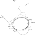
- Figure 2 shows a detailed view of the container 1 with the connector 4 mounted on the second receptacle 3.
- a compartment 12 is confined by the bottom side 2c of the first receptacle 2, the top side 3a or the top face 3e1 of the lid 3e of the second receptacle 3 and the lateral area 13 of the ferrule 4a as well as the outer surface 4d1 of the inner section 4d of the connector 4.
- the connector 4 or rather the ferrule 4a is firmly attached to the lid 3e and covers a part of the top face 3e1 adjacent to the lateral section 3e2 as well as a part of the lateral section 3e2 adjacent to the top face 3e1.
- the ferrule 4a further comprises a lateral circumferential groove 6 located within an inner section 4d of the ferrule 4a.
- the groove 6 is located between an inner face 4b1, 4c1 of a rim 4e and the outer surface 4d1 of the inner section 4d of the connector 4, wherein the groove 6 spaced to the outer surface 4d1 of an inner section 4d as well as to the inner surface of the rim 4e.
- the rim 4e comprises the upper 4b and lower 4c rim section.
- the groove 6 comprises an inner wall 6a and an outer wall 6b that are spaced from another in such a way that a tongue 7, which is arranged at the bottom side of the first receptacle 2 is form-fittingly engageable in the groove 6, wherein the lower rim section 4c circumferentially encloses the lateral section of the lid 3e2 of the second receptacle 3. Further the groove 6 is spaced to the outer surface 4d1 of an inner section 4d in such a way that the first receptacle 2 with its bottom side 2c and its tongue 7 fits into the upper 4b rim section.
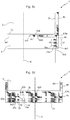
- Figures 3a-d show detailed cross-sectional views along the longitudinal axis of the container 5 and perpendicular to the transverse axis 5a of different possible connections of the connector and at least two receptacles according to embodiments of the present invention.
- Figures 3a-d show one connection and/or feature according to different embodiments of the invention, a combination of different connections and/or features of the embodiments is also possible, e.g. the connector 4 is connected to the first receptacle 2 through connection shown in fig. 3a , while at the same time it is connected to the second receptacle 3 through connection shown in fig. 3b .
- the connection features shown in Figure 3 are positioned on just one or several receptacles adjacent to the bottom sides and/or the lid or top sides or rather lateral faces.
- the lower rim section 4c circumferentially covers the lateral section 3e2 adjacent to the top face 3e1.
- the bottom side 2c of the first receptacle 2 is arranged above an upper surface 4d2 of the inner section 4d with respect to the longitudinal axis 5 of the container 1, wherein the top face 3e1 of the lid 3e of the second closable receptacle 3 is arranged below a lower surface 4d3 of the inner section 4d with respect to the longitudinal axis 5 of the container 1.
- the inner face 4b1 of the upper rim section 4b and the lateral face 2d of the first closable 2 receptacle are arranged against/facing each other, whereby, the inner face 4c1 of the lower rim section 4c and the lateral face 2e3 of the second closable receptacle 3 are arranged against/facing each other.
- FIG 3a the connection of the ferrule 4a to two receptacles with different transversal cross sections 2f, 3f is shown.
- the first receptacle 2 has a cross section 2f, which is smaller compared to the cross section 3f of the second receptacle 3.
- the diameter of the upper rim section 4b is smaller than the diameter of the lower rim section 4c so that the first receptacle 2 with its smaller cross section 2f (compared to 3f) fits into the upper rim section 4b and the second receptacle 3 with its larger cross section 3f (compared to 2f) fits into the lower rim section 4c.
- the groove 6 is positioned within the inner section 4d, spaced to the rim 4e and with its opening directed to the bottom side 2c of the first 2 receptacle.
- the tongue 7 of the first receptacle 2 is clasped in the groove 6 of the ferrule 4a, whereby the tongue 7 is arranged at the bottom side 2c of the first receptacle 2 and directed to the upper surface 4d2 of the inner section 4d of the ferrule 4a.
- the thickness of the rim 4e of the ferrule 4a is tapering at the upper edge 14 of the ferrule 4a forming an inner face 15 of the upper edge 14 of the ferrule 4a.
- the inner face 15 forms an angle 16 to the transverse axis 5a of the ferrule 4a of between 90° and 160°, preferred between 90° and 150°, more preferred between 110° and 130°.
- FIG. 3b another groove-tongue connection according to an embodiment of the invention is shown.
- a tongue 8 is arranged at the inner face 4c1 of the lower rim section 4c and parallel to the transverse axis 5a of the ferrule 4a.
- the tongue 8 is hooked in a groove 9 of the lid 3e of the second receptacle 3, wherein the groove 9 is positioned within and circumferentially encloses the lateral section 3e2 of the lid 3e of the second receptacle 3.
- the opening of the groove 9 is directed to the inner face 4c1 of the lower rim section 4c.
- FIG. 3c a screw thread connection according to an embodiment of the invention is shown.
- An external thread 17 is positioned at the inner face 4c1 of the lower rim section 4c with its crests 17a directed to the lateral area 13 or rather to the roots 18a of an internal thread 18 in a mounted state.
- the crests 17a and the roots 18a are helically arranged in such a way that they mesh when the connector 4 is mounted.
- An internal thread 18 is positioned at the lateral section 3e2 of the lid 3e of the second 3 closable receptacle, with its roots helically arranged around the lateral section 3e2 of the lid 3e of the second closable receptacle 3.
- the screw thread is formed as a trapezoidal thread, a cone/tapered thread and/or a round thread.
- FIG. 3d a bayonet connection according to an embodiment of the invention is shown.
- At least two pins 19 are located at the lateral section 3e2 of the lid of the second closable receptacle 3 and directed to the connector 4 with respect to its transverse axis 5a.
- the pins 19 are arranged at the lateral section 3e2 opposing each other.
- the pins 19 are radially shaped.
- the pins 19 have a front face 19a, which has a concave, convex or flat shape.
- At least two L-like-shaped slots 20 are positioned in the lower rim section 4c of the connector 4 with a first segment 20a opening at the lower edge 21 of the connector 4 and extending substantially in the longitudinal axis 5 of the container 1 and a second segment 20b, connected to the first segment 20a and extending from the first segment 20a in another direction, preferably substantially perpendicular to the longitudinal axis 5 of the container 1.
- the first 20a and the second segment 20b form an angle 22 of between 90° and 20°, preferred between 90 and 45°, more preferred between 90° and 70°.
- the L-like-shaped slots 20 are arranged in such a way that the pins 19 positioned at the lid 3e are slidable through an opening 20c of the first segment 20a and the second segment 20b by pushing and/or rotating the connector onto a receptacle.
Landscapes
- Engineering & Computer Science (AREA)
- Mechanical Engineering (AREA)
- Packaging Of Annular Or Rod-Shaped Articles, Wearing Apparel, Cassettes, Or The Like (AREA)
Abstract
The present invention relates to a Container for tobacco products comprising at least two closable receptacles and at least one connector, with which a bottom side of a first receptacle is detachably connectable to a top side of a second receptacle. The present invention also relates to a Method for connecting at least two closable receptacles with one connector, with which the bottom side of the first receptacle is detachably connected to the top side of the second receptacle. The first closable receptacle having a top side with a closable top side opening, a bottom side and at least one lateral face enclosing a first inner cavity, in which a first tobacco product or tobacco accessory is storable. The second closable receptacle having a top side with a top side opening, a bottom side and at least one lateral face enclosing a second inner cavity, in which a second tobacco product or tobacco accessory is storable.
Description
- The present invention relates to a container for tobacco products comprising at least two closable receptacles and at least one connector, with which the bottom side of a first receptacle is detachably connectable to the top side of a second receptacle. The present invention also relates to a method for connecting at least two closable receptacles with one connector, with which the bottom side of the first receptacle is detachably connected to the top side of the second receptacle.
- Many smokers like to make their own cigarettes by wrapping a rectangular sheet of cigarette wrapping paper of the length of the cigarette around loose tobacco and preferably a filter or by stuffing loose tobacco into tubes. While those sheets and tubes are generally presented in cardboard boxes, the loose tobacco is supplied in tins or pouch-style containers.
- If the tobacco is stored in a pouch, the tobacco begins to lose moisture and dry out, once the pouch is opened. As for making a cigarette a consumer needs both tobacco and cigarette papers or tubes respectively and preferably filters they tend to store papers/tubes and/or filters together with the loose tobacco within in the pouch or another container in order to prevent misplacing one of these constituents. However, if papers/tubes and/or filters are placed together with the tobacco within the same receptacle, the relatively high moisture level in tobacco can cause the paper material to become damp, making it impossible to use. The paper material can also become mixed up with the tobacco and may be hard to find when required.
- Dual compartment containers (
WO2017208154A1 ) or kits for handmade cigarettes comprising at least two compartments/receptacles, with one filled with tobacco and one filled with papers/tubes are therefore very common. However, with a dual container only one compartment can be used at a time. Thus, mostly, tobacco and paper/tubes are sold as separate items in different pack types. These pack types are connected via wrapper and cannot be re-attached once separated, even if connected with shrinking foil or tape. - The objective of the invention is therefore to provide connected receptacles that are easy to separate and re-connect either by the user or by machines so that the paper/tubes and the loose tobacco can be sold as one package, which is detachable and re-connectable multiple times.
- The afore-mentioned problems are eliminated by a container for tobacco products comprising at least a first and a second closable receptacle. The first receptacle may have a top side with a closable top side opening, a bottom side and at least one lateral face enclosing a first inner cavity, in which a first tobacco product or tobacco accessory is storable. The second closable receptacle may have a top side with a top side opening, a bottom side and at least one lateral face enclosing a second inner cavity, in which a second tobacco product or tobacco accessory is storable. The container further comprises at least one connector, with which the bottom side of the first receptacle is detachably connectable to the top side of the second receptacle. It is possible, that the receptacles are connected via a friction lock to the connector, i.e. the receptacles are detachably connected to the connector by means of friction/friction force. Therefore, preferably the receptacles and the connector and/or the corresponding parts of the receptacles and the corresponding parts of the connector are in direct contact with each other. The connector allows the sale and storage of the two receptacles connected to each other. Thus, the paper/tubes and the tobacco are connected so that a misplacement of one of these constituents is unlikely. Moreover, during automatic production and packaging of the receptacles the system just needs to put one connector on the top side of one receptacle and another receptacle on the connector. Preferably, the longitudinal axis of the container is similar or at least in parallel with the longitudinal axis of the connector and vice versa. Furthermore, the transverse axis of the container corresponds to the transverse axis of the connector and vice versa.
- In a preferred embodiment, the connector is a ferrule, having a longitudinal axis which is arranged perpendicularly to the surface of the bottom or top side of the receptacles, wherein the ferrule is slidable over a lower region of the lateral face adjacent to the bottom side of the first receptacle along a longitudinal axis of the container. A ferrule is the preferred form to connect receptacles, as with a hole in the middle of the connector, the connector can be easily attached to or detached from a receptacle. Moreover, when the ferrule is slidable over a lower region of the lateral face adjacent to the bottom face of the first receptacle, the ferrule can be moved with respect to the first receptacle instead of being fixedly attached to it. It is also possible that the connector is designed as a lid compatible to one of the receptacles and/or as any other form with a functionality compatible to a connection system of at least two receptacles.
- In a preferred embodiment, the second receptacle comprises a detachable lid to which the ferrule is firmly attached. This is advantageous, because the ferrule extends a gripping surface of the lid so that a user (or machine) can open the receptacle by gripping the larger (compared to the lid) ferrule. Preferably the ferrule is firmly, but also detachably attached to the lid of the second receptacle. The ferrule would then be reusable and can be used together with other receptacles and/or lids. It is also possible that the lid of the second receptacle and the ferrule are glued or welded, minimizing the risk to misplace one of them or to break one of them by trying to detach them. Moreover, it is possible that the ferrule and the lid of the second receptacle are formed as one-piece, which reduces the number of required production steps.
- In a preferred embodiment, the ferrule comprises at least one lateral circumferential groove in which a matching tongue of the first and/or second receptacle is engageable. Preferentially, the groove is arranged at an inner section of the ferrule and the tongue is positioned at the bottom side of the first receptacle and/or the top side of the second receptacle. It is also possible that the groove and/or tongue is partially interrupted. A system with a groove and a tongue allows a fixed attachment of the ferrule and the first and/or second receptacle. Either the ferrule or the first and/or second receptacle can be fixed by simply pressing one of them onto the other.
- In a preferred embodiment, the ferrule, having a tongue substantially perpendicular to its longitudinal axis and/or substantially parallel to the transverse axis, is firmly attached to the bottom side of the first receptacle and the lid of the second receptacle comprises a matching groove in which the tongue of the ferrule is engageable. Preferably, the tongue is arranged at an inner face of a rim of the ferrule and/or its inner section. It is possible that the matching groove is positioned at the lateral section or the top face of a lid of the second receptacle, wherein the
groove 9 is positioned within and circumferentially encloses the lateral section of the lid of the second receptacle. When the tongue of the ferrule is arranged parallel to its longitudinal axis, the matching groove of the lid can hold the ferrule simply by pressing the tongue into the lid. It is also possible, that the groove is positioned within the lateral face of the receptacle. This is advantageous in the case the ferrule is firmly attached to the lid of the second receptacle. - In a preferred embodiment, a face of a rim of the ferrule is tapering at least towards an upper and/or a lower edge of the ferrule forming an inner face of the upper edge of the ferrule, wherein an angle of the inner face to the longitudinal axis of the ferrule of between 90° and 160°, preferred between 90° and 150°, more preferred between 110° and 130°. With a tapering face the receptacles can easily be inserted into the ferrule.
- In a preferred embodiment, the first and/or second receptacle is detachably connectable to the connector via a screw thread. A screw thread provides a useful and strong connection, with which the first and/or second receptacle can be fixed to the connector. The user just needs to screw to properly lock the receptacles and the connector. Preferably the screw thread is a lug cap system, which could be easier to screw compared to a conventional screw thread.
- In another preferred embodiment, the first and/or second receptacle is detachably connectable to the connector via a bayonet mount. A bayonet mount or rather a bayonet system allows the fixation of the connector without screwing by means of multiple rotations and just requires a part rotation.
- In a preferred embodiment, the container comprises at least one compartment confined by the bottom side of the first receptacle, the top side of the second receptacle and a lateral area of the ferrule. The additional compartment can be used as space for e.g. some notes and/or a booklet and/or wrapping paper.
- In a preferred embodiment, the receptacles have the same transversal cross-section. That way the production can be facilitated because of just one production line is needed to produce both receptacles.
- In another preferred embodiment, the receptacles have a cylindrical shape. A cylindrical shape is easy to grab.
- In a preferred embodiment, the receptacles have a cuboid shape, preferably with sharp or rounded edges. That way the container provides flat surfaces, which are useful to show Information. Moreover, an edgy tongue of a receptacle can hook into a compatible groove of the connector, which provides a very strong connection
- It is conceivable, that the container comprises at least two receptacles having different shapes, e.g. cylindrical and cuboid.
- It is further conceivable, that a shape of the connector and/or the ferrule is matched to the shape of the respective receptacle. Particularly preferably, the upper rim section and the lower rim section of the rim of the connector and/or the ferrule are matched to the lower region of the lateral face of the first receptacle adjacent to the bottom side of the first receptacle or to the lateral section of the lid of the second receptacle, respectively.
- In another preferred embodiment, the receptacles have different transversal cross-sections. If one receptacle is smaller than the other, material can be saved in the production.
- In a preferred embodiment, the container comprises more than two receptacles and more than one connector with which the bottom side of the receptacles, with exception of the last receptacle, is detachably connectable to the top side of the adjacent receptacle, which is arranged adjacent to the bottom side of the respective receptacle. A container with more than two receptacles allows a consumer to store more than two tobacco articles at the same place without the risk to misplace one of the them, e.g. storing loose tobacco together with wrapping paper and filters and perhaps also semi-made cigarettes consisting of a tobacco rod wrapped in paper or two different sorts of tobacco together with tubes.
- The objective of the present invention is also achieved by a method for connecting at least a first and a second closable receptacle of a container for tobacco products. The method comprises the steps:
- a) Providing the at least first and second closable receptacle and a connector;
- b) Connecting the at least first and second closable receptacle by means of the connector;
- Disclosures and descriptions according to features of the container shall be disclosed and apply mutatis mutandis to the method and vice versa.
- Further advantages, objectives and features of the present invention will be described, by way of example only, in the following description with reference to the appended figures. In the figures, like components in different embodiments can exhibit the same reference symbols.
- The figures show:
- Fig. 1
- a schematic view of constituents of a container for tobacco products according to an embodiment of the present invention;
- Fig. 2
- a detailed view of the container with the connector mounted on the second receptacle according to an embodiment of the present invention;
- Fig. 3a-d
- detailed cross-sectional views of connections of the connector and a receptacle according to embodiments of the present invention.
- In
Figure 1 a schematic view of constituents of a cylindrically shapedcontainer 1 for tobacco products according to an embodiment of the invention is shown. Thecontainer 1 comprises a firstclosable receptacle 2, a secondclosable receptacle 3 and aconnector 4, which is formed as aferrule 4a. While the firstclosable receptacle 2 is arranged at theupper section 1a of thecontainer 1, the secondclosable receptacle 3 is positioned in thelower section 1c of thecontainer 1. Theconnector 4 is located in themiddle section 1b of thecontainer 1. - The first 2 and the second
closable receptacle 3 are both cylindrically shaped, concentrically arranged around thelongitudinal axis 5 of thecontainer 1, each of theclosable receptacles top side bottom side lateral face lid bottom sides top sides receptacles bottom side 2c of thefirst receptacle 2 is arranged spaced to thetop side 3a of thesecond receptacle 2. - The
lids lids top sides receptacles top side openings top side openings longitudinal axis 5 of thecontainer 1. Additionally, thelids lateral sides top side receptacles - Further, the
lids receptacles top side openings receptacles receptacles respective receptacle - The
ferrule 4a is positioned between the first 2 and the secondclosable receptacle 3 and connects them in a mounted state, wherein theferrule 4a comprises atransverse axis 5a, which is arranged parallel to the bottom sides 2c, 3c and thetop sides longitudinal axis 5 of the container and the lateral faces 2d, 3d. Further, theferrule 4a preferably comprises anupper rim section 4b and alower rim section 4c, wherein in a mounted state theupper rim section 4b circumferentially encloses a part of thelateral side 2d adjacent to thebottom side 2c of thefirst receptacle 2 and thelower rim section 4c circumferentially encloses a part of thelateral side 3d adjacent to thetop side 3a of thesecond receptacle 3 and/or the lateral section 3e2 of thelid 3e. Preferentially, the transversal cross section of theupper rim section 4b is smaller than the transversal cross section of thelower rim section 4c, which circumferentially encloses the lateral section 3e2 of thelid 3e of thesecond receptacle 3. Theferrule 4a also comprises alateral area 13 that includes at least an outer surface of the inner section 4d1, an inner face of the upper rim section 4b1, an inner face of the lower rim section 4c1, and/or an upper 4d2 and a lower 4d3 surface of aninner section 4d. -
Figure 2 shows a detailed view of thecontainer 1 with theconnector 4 mounted on thesecond receptacle 3. Acompartment 12 is confined by thebottom side 2c of thefirst receptacle 2, thetop side 3a or the top face 3e1 of thelid 3e of thesecond receptacle 3 and thelateral area 13 of theferrule 4a as well as the outer surface 4d1 of theinner section 4d of theconnector 4. Theconnector 4 or rather theferrule 4a is firmly attached to thelid 3e and covers a part of the top face 3e1 adjacent to the lateral section 3e2 as well as a part of the lateral section 3e2 adjacent to the top face 3e1. - The
ferrule 4a further comprises a lateralcircumferential groove 6 located within aninner section 4d of theferrule 4a. Thegroove 6 is located between an inner face 4b1, 4c1 of arim 4e and the outer surface 4d1 of theinner section 4d of theconnector 4, wherein thegroove 6 spaced to the outer surface 4d1 of aninner section 4d as well as to the inner surface of therim 4e. - The
rim 4e comprises the upper 4b and lower 4c rim section. Thegroove 6 comprises aninner wall 6a and anouter wall 6b that are spaced from another in such a way that atongue 7, which is arranged at the bottom side of thefirst receptacle 2 is form-fittingly engageable in thegroove 6, wherein thelower rim section 4c circumferentially encloses the lateral section of the lid 3e2 of thesecond receptacle 3. Further thegroove 6 is spaced to the outer surface 4d1 of aninner section 4d in such a way that thefirst receptacle 2 with itsbottom side 2c and itstongue 7 fits into the upper 4b rim section. -
Figures 3a-d show detailed cross-sectional views along the longitudinal axis of thecontainer 5 and perpendicular to thetransverse axis 5a of different possible connections of the connector and at least two receptacles according to embodiments of the present invention. AlthoughFigures 3a-d show one connection and/or feature according to different embodiments of the invention, a combination of different connections and/or features of the embodiments is also possible, e.g. theconnector 4 is connected to thefirst receptacle 2 through connection shown infig. 3a , while at the same time it is connected to thesecond receptacle 3 through connection shown infig. 3b . It is also possible, that the connection features shown inFigure 3 are positioned on just one or several receptacles adjacent to the bottom sides and/or the lid or top sides or rather lateral faces. - While the
inner section 4d covers a part of the top face 3e1 adjacent to the lateral section 3e2, thelower rim section 4c circumferentially covers the lateral section 3e2 adjacent to the top face 3e1. Thebottom side 2c of thefirst receptacle 2 is arranged above an upper surface 4d2 of theinner section 4d with respect to thelongitudinal axis 5 of thecontainer 1, wherein the top face 3e1 of thelid 3e of the secondclosable receptacle 3 is arranged below a lower surface 4d3 of theinner section 4d with respect to thelongitudinal axis 5 of thecontainer 1. Further, the inner face 4b1 of theupper rim section 4b and thelateral face 2d of the first closable 2 receptacle are arranged against/facing each other, whereby, the inner face 4c1 of thelower rim section 4c and the lateral face 2e3 of the secondclosable receptacle 3 are arranged against/facing each other. - In
Figure 3a the connection of theferrule 4a to two receptacles with differenttransversal cross sections first receptacle 2 has across section 2f, which is smaller compared to thecross section 3f of thesecond receptacle 3. The diameter of theupper rim section 4b is smaller than the diameter of thelower rim section 4c so that thefirst receptacle 2 with itssmaller cross section 2f (compared to 3f) fits into theupper rim section 4b and thesecond receptacle 3 with itslarger cross section 3f (compared to 2f) fits into thelower rim section 4c. - The
groove 6 is positioned within theinner section 4d, spaced to therim 4e and with its opening directed to thebottom side 2c of the first 2 receptacle. In a mounted state thetongue 7 of thefirst receptacle 2 is clasped in thegroove 6 of theferrule 4a, whereby thetongue 7 is arranged at thebottom side 2c of thefirst receptacle 2 and directed to the upper surface 4d2 of theinner section 4d of theferrule 4a. - Preferably, the thickness of the
rim 4e of theferrule 4a is tapering at theupper edge 14 of theferrule 4a forming aninner face 15 of theupper edge 14 of theferrule 4a. Theinner face 15 forms anangle 16 to thetransverse axis 5a of theferrule 4a of between 90° and 160°, preferred between 90° and 150°, more preferred between 110° and 130°. - In
Figure 3b another groove-tongue connection according to an embodiment of the invention is shown. A tongue 8 is arranged at the inner face 4c1 of thelower rim section 4c and parallel to thetransverse axis 5a of theferrule 4a. In a mounted state, the tongue 8 is hooked in agroove 9 of thelid 3e of thesecond receptacle 3, wherein thegroove 9 is positioned within and circumferentially encloses the lateral section 3e2 of thelid 3e of thesecond receptacle 3. The opening of thegroove 9 is directed to the inner face 4c1 of thelower rim section 4c. - In
Figure 3c a screw thread connection according to an embodiment of the invention is shown. Anexternal thread 17 is positioned at the inner face 4c1 of thelower rim section 4c with itscrests 17a directed to thelateral area 13 or rather to theroots 18a of aninternal thread 18 in a mounted state. Thecrests 17a and theroots 18a are helically arranged in such a way that they mesh when theconnector 4 is mounted. Aninternal thread 18 is positioned at the lateral section 3e2 of thelid 3e of the second 3 closable receptacle, with its roots helically arranged around the lateral section 3e2 of thelid 3e of the secondclosable receptacle 3. Preferably, the screw thread is formed as a trapezoidal thread, a cone/tapered thread and/or a round thread. - In
Figure 3d a bayonet connection according to an embodiment of the invention is shown. At least two pins 19 (one is not shown inFigure 3d ) are located at the lateral section 3e2 of the lid of the secondclosable receptacle 3 and directed to theconnector 4 with respect to itstransverse axis 5a. Preferably thepins 19 are arranged at the lateral section 3e2 opposing each other. Preferably, thepins 19 are radially shaped. Further, thepins 19 have afront face 19a, which has a concave, convex or flat shape. At least two L-like-shapedslots 20 are positioned in thelower rim section 4c of theconnector 4 with afirst segment 20a opening at thelower edge 21 of theconnector 4 and extending substantially in thelongitudinal axis 5 of thecontainer 1 and asecond segment 20b, connected to thefirst segment 20a and extending from thefirst segment 20a in another direction, preferably substantially perpendicular to thelongitudinal axis 5 of thecontainer 1. Preferable, the first 20a and thesecond segment 20b form anangle 22 of between 90° and 20°, preferred between 90 and 45°, more preferred between 90° and 70°. The L-like-shapedslots 20 are arranged in such a way that thepins 19 positioned at thelid 3e are slidable through anopening 20c of thefirst segment 20a and thesecond segment 20b by pushing and/or rotating the connector onto a receptacle. - The features and descriptions according of the different embodiments of the present invention shown in
Figures 1 ,2 and3a-d shall be disclosed and apply mutatis mutandis to each of the other embodiments. - List of reference symbols
- 1.
- Container
- 1a.
- Upper section of the container
- 1b.
- Middle section of the container
- 1c.
- Lower section of the container
- 2.
- First closable receptacle
- 2a.
- Top side of the first closable receptacle
- 2b.
- Closable top side opening of the first closable receptacle
- 2c.
- Bottom side of the first closable receptacle
- 2d.
- Lateral face of the first closable receptacle
- 2e.
- Lid of the of the first closable receptacle
- 2e1.
- Top face of the lid of the first closable receptacle
- 2e2.
- Lateral section of the lid of the first closable receptacle
- 2e3.
- Lateral face of the lid of the first closable receptacle
- 2f.
- Cross section of the first closable receptacle
- 3.
- Second closable receptacle
- 3a.
- Top side of the second closable receptacle
- 3b.
- Closable top side opening of the second closable receptacle
- 3c.
- Bottom side of the second closable receptacle
- 3d.
- Lateral face of the second closable receptacle
- 3e.
- Lid of the second closable receptacle
- 3e1.
- Top face of the lid of the second closable receptacle
- 3e2.
- Lateral section of the lid of the second closable receptacle
- 3f.
- Cross section of the second closable receptacle
- 4.
- Connector
- 4a.
- Ferrule
- 4b.
- Upper rim section
- 4b1.
- Inner face of the upper rim section
- 4c.
- Lower rim section
- 4c1.
- Inner face of the lower rim section
- 4d.
- Inner section
- 4d1.
- Outer surface of the inner section
- 4d2.
- Upper surface of the inner section
- 4d3.
- Lower surface of the inner section
- 4e.
- Rim of the connector
- 5.
- Longitudinal axis
- 5a.
- Transverse axis
- 6.
- groove of the connector
- 6a.
- Inner wall of the groove of the connector
- 6b.
- Outer wall of the groove of the connector
- 7.
- Tongue of the first and/or second receptacle
- 8.
- Tongue of the ferrule
- 9.
- groove of the lid of the second receptacle
- 10.
- Screw thread
- 11.
- Bayonet mount
- 12.
- Compartment
- 13.
- Lateral area of the ferrule
- 14.
- Upper edge of the ferrule
- 15.
- Inner face of the upper edge of the ferrule
- 16.
- Angle between the inner face of the upper edge and the longitudinal axis of the connector.
- 17.
- External thread
- 17a.
- Crests of the external thread
- 18.
- Internal thread
- 18a.
- roots of the internal thread
- 19.
- Pins
- 19a.
- Front face of the pins
- 20.
- L-like-shaped slots
- 20a.
- first segment
- 20b.
- second segment
- 20c.
- Opening of the first segment
- 21.
- Lower edge of the ferrule
- 22.
- Angle between first and second segment
Claims (14)
- Container (1) for tobacco products wherein the Container (1) comprises at least a first closable receptacle (2) having a top side (2a) with a closable top side opening (2b), a bottom side (2c) and at least one lateral face (2d) enclosing a first inner cavity, in which a first tobacco product or tobacco accessory is storable, and at least a second closable receptacle (3) having a top side (3a) with a top side opening (3b), a bottom side (3c) and at least one lateral face (3d) enclosing a second inner cavity, in which a second tobacco product or tobacco accessory is storable,
characterized in that,
the container (1) further comprises at least one connector (4), with which the bottom side (2c) of the first receptacle is detachably connectable to the top side (3a) of the second receptacle. - Container (1) for tobacco products according to claim 1,
characterized in that,
the connector (4) is a ferrule (4a), having a longitudinal axis (5) which is arranged perpendicularly to the surface of the bottom (2c, 3c) or top side (2b, 3b) of the receptacles (2, 3), wherein the ferrule (4a) is slidable over a lower region of the lateral face (2d) adjacent to the bottom side (2c) of the first receptacle (2). - Container (1) for tobacco products according to claim 2,
characterized in that,
the second receptacle (3) comprises a detachable lid (3e) to which the ferrule (4a) is firmly attached. - Container (1) for tobacco products according to claim 2 or 3,
characterized in that,
the ferrule (4a) comprises at least one lateral circumferential groove (6) in which a matching tongue (7) of the first (2) and/or second receptacle (3) is engageable. - Container (1) for tobacco products according to claims 2-4,
characterized in that,
the ferrule (4a), having a tongue (8) substantially perpendicular to its longitudinal axis (5), is firmly attached to the bottom side (2c) of the first receptacle (2) and the lid (3e) of the second receptacle (3) comprises a matching groove (9) in which the tongue (8) of the ferrule (4a) is engageable. - Container (1) for tobacco products according to one of the preceding claims,
characterized in that,
the first (2) and/or second receptacle (3) is detachably connectable to the connector (4) via a screw thread (10). - Container (1) for tobacco products according to one of the preceding claims,
characterized in that,
the first (2) and/or second receptacle (3) is detachably connectable to the connector (4) via a bayonet mount (11). - Container (1) for tobacco products according to one of the preceding claims,
characterized in that,
the container (1) comprises at least one compartment (12) confined by the bottom side (2c) of the first receptacle (2), the top side (3a) of the second receptacle (3) and a lateral area (13) of the ferrule (4a). - Container (1) for tobacco products according to one of the preceding claims,
characterized in that,
the receptacles (2, 3) have the same transversal cross-section (2f, 3f). - Container (1) for tobacco products according to one of the preceding claims,
characterized in that,
the receptacles (2, 3) have a cylindrical shape. - Container (1) for tobacco products according to claims 1-5 and 8-9,
characterized in that,
the receptacles (2, 3) have a cuboid shape. - Container (1) for tobacco products according to claims 1-8 and 10-11,
characterized in that,
the receptacles (2, 3) have different transversal cross-sections (2f, 3f). - Container (1) for tobacco products according to one of the preceding claims,
characterized in that,
the container (1) comprises more than two receptacles and more than one connector (4) with which the bottom side of the receptacles, with exception of the last receptacle, is detachably connectable to the top side of the adjacent receptacle, which is arranged adjacent to the bottom side of the respective receptacle. - Method for connecting at least a first (2) and a second (3) closable receptacle of a container (1) for tobacco products, comprising the steps:c) Providing the at least first (2) and second closable receptacle (3) and a connector (4);d) Connecting the at least first (2) and second closable receptacle (3) by means of the connector (4);wherein the receptacles (2,3) each have a top side (2a, 3a) with a closable top side opening (2b, 3b), a bottom side (2c, 3c) and at least one lateral face (2d, 3d) enclosing a first inner cavity, in which a first tobacco product or tobacco accessory is storable, wherein the bottom side (2c) of the first receptacle (2) is detachably connected to the top side (3a) of the second receptacle (3) by the connector (4).
Priority Applications (1)
| Application Number | Priority Date | Filing Date | Title |
|---|---|---|---|
| EP19175213.8A EP3738899A1 (en) | 2019-05-17 | 2019-05-17 | Container for tobacco products |
Applications Claiming Priority (1)
| Application Number | Priority Date | Filing Date | Title |
|---|---|---|---|
| EP19175213.8A EP3738899A1 (en) | 2019-05-17 | 2019-05-17 | Container for tobacco products |
Publications (1)
| Publication Number | Publication Date |
|---|---|
| EP3738899A1 true EP3738899A1 (en) | 2020-11-18 |
Family
ID=66625004
Family Applications (1)
| Application Number | Title | Priority Date | Filing Date |
|---|---|---|---|
| EP19175213.8A Withdrawn EP3738899A1 (en) | 2019-05-17 | 2019-05-17 | Container for tobacco products |
Country Status (1)
| Country | Link |
|---|---|
| EP (1) | EP3738899A1 (en) |
Citations (6)
| Publication number | Priority date | Publication date | Assignee | Title |
|---|---|---|---|---|
| DE1657158A1 (en) * | 1967-12-01 | 1971-03-25 | Eduardo S Ind | Additional vessel |
| DE8914209U1 (en) * | 1988-12-01 | 1990-03-29 | Karl Huber Verpackungswerke GmbH + Co, 7110 Öhringen | Double container for two-component substances |
| WO2005057357A2 (en) * | 2003-12-04 | 2005-06-23 | Sybil Smith | Inventory control system and method especially for pharmaceuticals |
| US20070084863A1 (en) * | 2005-10-14 | 2007-04-19 | W.C. Bradley Company | Stackable spice container assembly having a removable accessory |
| US20080083639A1 (en) * | 2006-10-04 | 2008-04-10 | Carol Peterman | Stackable container systems and methods |
| WO2017208154A1 (en) | 2016-05-31 | 2017-12-07 | Philip Morris Products S.A. | Opposing compartment tobacco container |
-
2019
- 2019-05-17 EP EP19175213.8A patent/EP3738899A1/en not_active Withdrawn
Patent Citations (6)
| Publication number | Priority date | Publication date | Assignee | Title |
|---|---|---|---|---|
| DE1657158A1 (en) * | 1967-12-01 | 1971-03-25 | Eduardo S Ind | Additional vessel |
| DE8914209U1 (en) * | 1988-12-01 | 1990-03-29 | Karl Huber Verpackungswerke GmbH + Co, 7110 Öhringen | Double container for two-component substances |
| WO2005057357A2 (en) * | 2003-12-04 | 2005-06-23 | Sybil Smith | Inventory control system and method especially for pharmaceuticals |
| US20070084863A1 (en) * | 2005-10-14 | 2007-04-19 | W.C. Bradley Company | Stackable spice container assembly having a removable accessory |
| US20080083639A1 (en) * | 2006-10-04 | 2008-04-10 | Carol Peterman | Stackable container systems and methods |
| WO2017208154A1 (en) | 2016-05-31 | 2017-12-07 | Philip Morris Products S.A. | Opposing compartment tobacco container |
Similar Documents
| Publication | Publication Date | Title |
|---|---|---|
| CA2735903C (en) | Container with two opposing lids | |
| US8348053B2 (en) | Adjacent article package for consumer products | |
| JP2010524801A (en) | Smoking package | |
| CN102083710A (en) | Packet and corresponding blank | |
| JP5719307B2 (en) | Container with hinge lid | |
| US5743397A (en) | Toilet paper storage receptacle | |
| EP3166860A1 (en) | Rigid package of smoke articles | |
| KR20050106517A (en) | Smoking article pack blank(s) | |
| EP3079997B1 (en) | Packaging for smoking articles | |
| US20180346234A1 (en) | Pack for consumer goods | |
| MX2011005349A (en) | Package for smoking articles. | |
| US2331901A (en) | Packaging | |
| CN104136332B (en) | The rigid package of medicated cigarette | |
| RU2762811C1 (en) | Child-proof container | |
| WO2012164247A1 (en) | A wrapper assembly for smoking articles | |
| KR20180019533A (en) | Containers for consumer products with sliding parts | |
| EP3099585B1 (en) | A rigid packet of smoking articles with inner volume divided into two distinct chambers | |
| KR200319555Y1 (en) | Eag packing container | |
| WO2016102557A1 (en) | Container with connected inner liner and corresponding packaging method | |
| EP3025979A1 (en) | Container for consumer articles with two spacers and process for making same | |
| EP3166857A1 (en) | Container for consumer articles comprising an inner tray element | |
| JPH1035645A (en) | Carton with outlet | |
| WO2017042332A1 (en) | Blank for an inner liner, inner liner, and container with spacer | |
| WO2016023967A1 (en) | Container for consumer articles with in depth inner frame | |
| WO2011147572A1 (en) | Smoking article removal system and container |
Legal Events
| Date | Code | Title | Description |
|---|---|---|---|
| PUAI | Public reference made under article 153(3) epc to a published international application that has entered the european phase |
Free format text: ORIGINAL CODE: 0009012 |
|
| STAA | Information on the status of an ep patent application or granted ep patent |
Free format text: STATUS: THE APPLICATION HAS BEEN PUBLISHED |
|
| AK | Designated contracting states |
Kind code of ref document: A1 Designated state(s): AL AT BE BG CH CY CZ DE DK EE ES FI FR GB GR HR HU IE IS IT LI LT LU LV MC MK MT NL NO PL PT RO RS SE SI SK SM TR |
|
| AX | Request for extension of the european patent |
Extension state: BA ME |
|
| STAA | Information on the status of an ep patent application or granted ep patent |
Free format text: STATUS: THE APPLICATION IS DEEMED TO BE WITHDRAWN |
|
| 18D | Application deemed to be withdrawn |
Effective date: 20210519 |