EP3738885A1 - Mount arrangement for torque roll vibration isolation - Google Patents
Mount arrangement for torque roll vibration isolation Download PDFInfo
- Publication number
- EP3738885A1 EP3738885A1 EP20175282.1A EP20175282A EP3738885A1 EP 3738885 A1 EP3738885 A1 EP 3738885A1 EP 20175282 A EP20175282 A EP 20175282A EP 3738885 A1 EP3738885 A1 EP 3738885A1
- Authority
- EP
- European Patent Office
- Prior art keywords
- links
- roll
- axis
- engine
- freedom
- Prior art date
- Legal status (The legal status is an assumption and is not a legal conclusion. Google has not performed a legal analysis and makes no representation as to the accuracy of the status listed.)
- Granted
Links
Images



Classifications
-
- B—PERFORMING OPERATIONS; TRANSPORTING
- B64—AIRCRAFT; AVIATION; COSMONAUTICS
- B64D—EQUIPMENT FOR FITTING IN OR TO AIRCRAFT; FLIGHT SUITS; PARACHUTES; ARRANGEMENT OR MOUNTING OF POWER PLANTS OR PROPULSION TRANSMISSIONS IN AIRCRAFT
- B64D27/00—Arrangement or mounting of power plants in aircraft; Aircraft characterised by the type or position of power plants
- B64D27/40—Arrangements for mounting power plants in aircraft
-
- B—PERFORMING OPERATIONS; TRANSPORTING
- B64—AIRCRAFT; AVIATION; COSMONAUTICS
- B64D—EQUIPMENT FOR FITTING IN OR TO AIRCRAFT; FLIGHT SUITS; PARACHUTES; ARRANGEMENT OR MOUNTING OF POWER PLANTS OR PROPULSION TRANSMISSIONS IN AIRCRAFT
- B64D27/00—Arrangement or mounting of power plants in aircraft; Aircraft characterised by the type or position of power plants
- B64D27/40—Arrangements for mounting power plants in aircraft
- B64D27/402—Arrangements for mounting power plants in aircraft comprising box like supporting frames, e.g. pylons or arrangements for embracing the power plant
-
- B—PERFORMING OPERATIONS; TRANSPORTING
- B64—AIRCRAFT; AVIATION; COSMONAUTICS
- B64D—EQUIPMENT FOR FITTING IN OR TO AIRCRAFT; FLIGHT SUITS; PARACHUTES; ARRANGEMENT OR MOUNTING OF POWER PLANTS OR PROPULSION TRANSMISSIONS IN AIRCRAFT
- B64D27/00—Arrangement or mounting of power plants in aircraft; Aircraft characterised by the type or position of power plants
- B64D27/02—Aircraft characterised by the type or position of power plants
- B64D27/10—Aircraft characterised by the type or position of power plants of gas-turbine type
- B64D27/12—Aircraft characterised by the type or position of power plants of gas-turbine type within, or attached to, wings
-
- B—PERFORMING OPERATIONS; TRANSPORTING
- B64—AIRCRAFT; AVIATION; COSMONAUTICS
- B64F—GROUND OR AIRCRAFT-CARRIER-DECK INSTALLATIONS SPECIALLY ADAPTED FOR USE IN CONNECTION WITH AIRCRAFT; DESIGNING, MANUFACTURING, ASSEMBLING, CLEANING, MAINTAINING OR REPAIRING AIRCRAFT, NOT OTHERWISE PROVIDED FOR; HANDLING, TRANSPORTING, TESTING OR INSPECTING AIRCRAFT COMPONENTS, NOT OTHERWISE PROVIDED FOR
- B64F5/00—Designing, manufacturing, assembling, cleaning, maintaining or repairing aircraft, not otherwise provided for; Handling, transporting, testing or inspecting aircraft components, not otherwise provided for
- B64F5/10—Manufacturing or assembling aircraft, e.g. jigs therefor
-
- F—MECHANICAL ENGINEERING; LIGHTING; HEATING; WEAPONS; BLASTING
- F16—ENGINEERING ELEMENTS AND UNITS; GENERAL MEASURES FOR PRODUCING AND MAINTAINING EFFECTIVE FUNCTIONING OF MACHINES OR INSTALLATIONS; THERMAL INSULATION IN GENERAL
- F16C—SHAFTS; FLEXIBLE SHAFTS; ELEMENTS OR CRANKSHAFT MECHANISMS; ROTARY BODIES OTHER THAN GEARING ELEMENTS; BEARINGS
- F16C7/00—Connecting-rods or like links pivoted at both ends; Construction of connecting-rod heads
- F16C7/04—Connecting-rods or like links pivoted at both ends; Construction of connecting-rod heads with elastic intermediate part of fluid cushion
-
- F—MECHANICAL ENGINEERING; LIGHTING; HEATING; WEAPONS; BLASTING
- F16—ENGINEERING ELEMENTS AND UNITS; GENERAL MEASURES FOR PRODUCING AND MAINTAINING EFFECTIVE FUNCTIONING OF MACHINES OR INSTALLATIONS; THERMAL INSULATION IN GENERAL
- F16F—SPRINGS; SHOCK-ABSORBERS; MEANS FOR DAMPING VIBRATION
- F16F15/00—Suppression of vibrations in systems; Means or arrangements for avoiding or reducing out-of-balance forces, e.g. due to motion
- F16F15/02—Suppression of vibrations of non-rotating, e.g. reciprocating systems; Suppression of vibrations of rotating systems by use of members not moving with the rotating systems
- F16F15/04—Suppression of vibrations of non-rotating, e.g. reciprocating systems; Suppression of vibrations of rotating systems by use of members not moving with the rotating systems using elastic means
Definitions
- the disclosure relates to aircraft engines and, more particularly, to a rotary engine mounting arrangement.
- Rotary engines generate significant alternating axial torque forces due to the nature of the combustion process.
- a low stiffness engine mount is desirable to limit the torque forces and vibration transmitted to the aircraft structure due to the alternating axial torque.
- a high mount stiffness is desirable in many engine installations, due to maximum allowable deflection limitations (ex. maximum shaft misalignments for turboshaft engines) on the translational and rotational deflection of an engine under high gravity loadings.
- an aircraft engine assembly comprises a rotary engine having a roll axis, a pitch axis and a yaw axis extending through a center of gravity of the rotary engine, a first set of one-degree-of-freedom links mounted to a first side and a second side of the rotary engine, the first set of one-degree-of-freedom links having a distal end configured to be mounted to an aircraft and a proximal end mounted to the rotary engine, the first set of one-degree-of-freedom links positioned relative to the rotary engine to have respective reaction axes passing through the roll axis, and a second set of links having a distal end configured to be mounted to the aircraft and a proximal end mounted to the rotary engine, the second set of links positioned relative to the rotary engine to have respective reaction axes transversally spaced-apart from the roll axis, wherein the reaction axes (otherwise known as reaction vectors) extend in the direction of
- the first set of one-degree-of-freedom links has a first mounting stiffness
- the second set of links has a second mounting stiffness, wherein the second mounting stiffness is less than the first mounting stiffness, the mounting stiffness being the stiffness of elastomeric bushings provided at the ends of the respective links and/or mounts, the mounting stiffness being the stiffness of elastomeric bushings provided at the ends of the respective links and/or mounts.
- the first set of one-degree-of-freedom links include a pair of forward links and a pair of rearward link and an axial constraint link having a reaction axis parallel to the roll axis; the forward links, the rearward links and the axial constraint link having a first mounting stiffness, the second set of links having a second mounting stiffness, wherein the second mounting stiffness is less than the first mounting stiffness, the mounting stiffness being the stiffness of elastomeric bushings provided at the ends of the respective links and/or mounts.
- the second set of links comprises: a pair of one-degree-of-freedom roll links, the roll links having reaction axes non-parallel to the roll axis and spaced a transverse distance X from the roll axis, wherein the reaction axis of the roll link extends along its longitudinal axis, and/or the roll link has pin ends.
- the pair of one-degree-of-freedom roll links is an opposing pair of said one-degree-of-freedom roll links disposed on opposing sides of the roll axis.
- links comprises a pair of A-frames each having two non-parallel one-degree-of-freedom links, each non-parallel one-degree-of-freedom link having a distal end configured to be mounted to the aircraft spaced apart an axial distance and a proximal end mounted to the rotary engine.
- proximal ends of the non-parallel one-degree-of-freedom links of the A-frame are joined at a trunnion.
- the trunnion includes an axial segment defining the axial constraint having the first mounting stiffness and a radial segment defining the roll constraint having the second mounting stiffness.
- the pair of A-frames is an opposing pair of said A-frames disposed on opposing sides of the roll axis.
- a method of mounting a rotary engine to an aircraft structure wherein the engine has a three orthogonal axes comprising a roll axis, a pitch axis, and a yaw axis extending through a center of gravity of the rotary engine, the method comprising mounting a forward portion of the engine to the aircraft structure with an opposing pair of non-parallel one-degree-of-freedom forward links having a reaction axis passing through the roll axis, mounting a rearward portion of the engine to the aircraft structure with an opposing pair of non-parallel one-degree-of-freedom rearward links having a reaction axis passing through the roll axis, axially constraining the engine with an axial constraint having a reaction axis parallel to the roll axis, and rotationally constraining the engine with a roll constraint having a moment reaction about the roll axis wherein the forward links, rearward links and axial constraint have a first mounting stiffness
- the engine is rotationally constrained about the roll axis using a one-degree-of-freedom roll link having a reaction axis non-parallel to the roll axis and spaced a transverse distance from the roll axis, wherein the reaction axis of the roll link extends along its longitudinal axis, and/or the roll link has pin ends.
- the engine is rotationally constrained about the roll axis and axially constrained parallel to the roll axis using a pair of opposing A-frames disposed on opposing sides of the roll axis.
- the A-frames have two said one-degree-of-freedom roll links joined at a transverse trunnion.
- the trunnion includes an axial segment defining the axial constraint having the first mounting stiffness and a radial segment defining the roll constraint having the second mounting stiffness.
- an aircraft mount for a rotary engine comprising an opposing pair of non-parallel one-degree-of-freedom forward links attached to a forward portion of the rotary engine and an opposing pair of non-parallel one-degree-of-freedom rearward links attached to a rearward portion of the rotary engine, the forward and rearward links having respective reaction axes passing through a torque roll axis of the rotary engine, and an A-frame link on each side of the engine between the forward and rearward links, the A-frame link oriented with a reaction axis transversely spaced apart from the torque roll axis, the reaction axis of the A-frame link being non-parallel to the torque roll axis and configured to restrain axial and roll movement, wherein the roll movement is restrained with a roll constraint of roll stiffness lower than an axial stiffness of an axial constraint and lower than a link stiffness of the non-parallel one-degree-of-freedom forward and rearward
- the A-frame link includes a trunnion mounted to the engine.
- the trunnion includes an axial segment defining the axial constraint having the axial stiffness and a radial segment defining the roll constraint having the roll stiffness.
- Figure 1 shows an example aircraft 1 with a rotary engine 2 driving a propeller 3.
- the present description relates to the mounting arrangement for mounting such a rotary engine 2 to the aircraft structure using struts or links.
- Fig. 1 illustrates an airplane, it is understood that the mounting arrangement could also be used for helicopter installations.
- the mounting arrangement could be used to mount a compounded turboshaft engine including at least one rotary engine (e.g. A Wankel engine) compounding power with a turbine, to the structure of a helicopter.
- a compounded turboshaft engine including at least one rotary engine (e.g. A Wankel engine) compounding power with a turbine
- Figure 2 shows an isometric schematic view of a first mounting arrangement where the engine mass is depicted for clarity as a sphere 4 having a roll axis 5, a yaw axis 15 and a pitch axis 14 extending through the center of gravity 6 of the sphere 4.
- the rotary engine 2 mass depicted as a sphere 4 is supported on the aircraft structure by a front mount, a rear mount and an intermediate mount.
- the front mount includes two non-parallel one-degree-of-freedom (1DOF) links 7 attached to either side of the engine 2 at a same axial station.
- the rear mount includes two non-parallel 1 DOF links 8 attached to either side of the engine 2 at a same axial station. The reaction axis of these links will extend through the link longitudinal axes.
- the forward links 7 and rearward links 8 are arranged with their reaction vectors 11 directed through the roll axis 5. Accordingly, the forward and rearward links 7, 8 do not constrain roll rotation about the roll axis 5 and do not constrain axial translation parallel to the roll axis 5.
- the forward and rearward links 7, 8 do constrain pitch rotation and yaw rotation.
- the forward and rearward links 7, 8 also constrain translation parallel to the pitch and yaw axes 14 ,15 (they resist vertical and lateral movements).
- the forward and rearward links 7, 8 have a high stiffness to restrict deflection of the engine.
- the intermediate mount includes a pair of A-frames 9 on each side of the engine 2 at a same axial station.
- Each A-frame 9 has a trunnion 10 at its apex.
- the A-frames 9 restrain axial translation parallel to the roll axis 5 as well as translation along the yaw axis 15.
- the stiffness at each of these engine interfaces can be controlled using elastomeric isolators so that the stiffness along the yaw axis 15 is low and the axial stiffness along roll axis 5 is high.
- the A-frames 9 also constrain rotation about the roll axis 5.
- the trunnion 10 exerts a moment force to constrain roll rotation since the trunnions 10 are disposed a distance "x" from the roll axis 5.
- the A-frames will have reaction axes in the plane of the A-frame. These exert a "moment reaction” or vector that is laterally spaced from the center of gravity. Since the A-frame is a triangular structure with ball or pin joints at the ends, the resultant reaction forces/vectors exerted by the A-frame members would resolve to two orthogonal resultant reaction forces in the plane of the A-frame (i.e.: a plane defined by 3 points on the axes about which the pin ends rotate).
- lateral rigid body motion along the pitch axis 14 is restricted by the forward and rearward links 7, 8.
- Axial rigid body motion along the roll axis 5 is restricted by axial reactions of the intermediate A-frames 9.
- Vertical rigid body motion along yaw axis 15 is restricted by all links 7, 8 and 9, but is dominated by the stiffer forward and rearward links 7, 8.
- Rotation about the roll axis 5 is only resisted by vertical reactions of the 2 intermediate mount A-frames 9.
- Rotation about the pitch axis 14 is predominantly resisted by the forward and rearward mount planes. Rotation about the yaw axis 15 is resisted at all mounts.
- This exemplary mount system contains a single DOF redundancy in that the system continues to restrict all degrees of freedom with any single link failed.
- the embodiment shown in Fig. 2 can be described as 8 1DOF links arranged in a 1-1-2-2-1-1 configuration in order to decouple the torque roll mode from other degrees of freedom.
- This allows the stiffness in the alternating torque direction to remain low while restricting other degrees of freedom in a stiff manner.
- the result is low vibratory force transmission through the mounts while maintaining low deflections under high g loading.
- This arrangement can be used on any engine with high alternating torques which requires low vibratory force transmission and low deflection under g loading.
- the reaction axis of these links will extend through the link longitudinal axes.
- FIG. 3 shows a second example mounting arrangement where the trunnion 10 is supported by a roll link 12. Axial translation is constrained by axial link 13.
- the mounting arrangement permits use of a relatively high mounting stiffness to restrict deflection of the engine and a relatively low mounting stiffness to restrict roll rotation about the roll axis 5.
- elastomeric bushings of the required low mounting stiffness can be used in the trunnions 10 whereas elastomeric bushings of the required high mounting stiffness can be used in the connection of the links 7, 8 and 13.
- the reaction axis of the roll link 12 will extend through the link longitudinal axes.
- Figure 4 shows a third mounting arrangement where the two rearward links 8 have been rotated 180 degrees about the roll axis 5.
- the links 7, 8 can be rotated in a mounting plane about the roll axis 5 provided that their reactions 11 remain passing through the roll axis 5 which enables the engine to be mounted from below, from above or from one side.
- the low mounting stiffness for roll constraint remains decoupled from the other constraints having high mounting stiffness.
- the tendency of the rotary engine to exert alternating roll torque forces on the supporting aircraft structure can be isolated with a low mounting stiffness bushing while high mounting stiffness restraints can be provided to limit deflection, pitch rotation and yaw rotation. Isolation is achieved by positioning the resonant frequency well below the excitation frequency, in a particular case by using a low stiffness in the torque roll axis.
- the mounting arrangement can be used on a rotary engine with high alternating roll torque forces which require low vibratory force transmission while retaining low deflection under g loading in flight. Further if any single link fails, the mounting arrangement continues to restrict all degrees of freedom providing a redundancy.
- the roll restraint (roll link 12 and trunnion 10) can provide a low stiffness independent of the high stiffness restraints of axial translation, pitch rotation, yaw rotation and linear translation in all directions.
- Figure 3 shows mounting arrangement for mounting the rotary engine 2 to the aircraft structure 1 with links 7, 8, 12 and 13 each having one degree-of-freedom.
- the engine is represented in the schematic views as a sphere 4 with a center of gravity 6 through which the roll axis 5 passes.
- the engine mass has a three orthogonal axes all passing through the engine center of gravity 6 namely: a roll axis 5 ; a pitch axis 14; and a yaw axis 15.
- a forward constraint is arranged in a plane orthogonal to the roll axis 5.
- the forward constraint includes two non-parallel one-degree-of-freedom forward links 7 each having a distal end 16 adapted to be mounted to the aircraft structure and a proximal end 17 adapted to be mounted to the exterior of the rotary engine.
- the proximal ends 17 can include an elastomeric bushing having a high stiffness to resist deflection of the engine.
- Each forward link 7 has a reaction axis 11 passing through the roll axis 5 and passing through the proximal and distal ends 17, 16 of the forward link 7.
- a rearward constraint is arranged in a plane orthogonal to the roll axis 5.
- the rearward constraint includes two non-parallel one-degree-of-freedom rearward links 8 each having a distal end 18 adapted to be mounted to the aircraft structure and a proximal end 19 adapted to be mounted to the exterior of the rotary engine.
- Each rearward link 8 has a reaction axis 11 passing through the roll axis 5 and passing through the proximal and distal ends 19, 18 of the rearward link 8.
- the proximal ends 19 can include an elastomeric bushing having a high stiffness to resist deflection of the engine.
- a separate one-degree-of-freedom axial link 13 serves as an axial constraint having a reaction axis parallel to the roll axis 5.
- the axial link is oriented at an angle with a distal end 20 adapted for mounting to the aircraft structure and a proximal end 21 disposed on the roll axis 5.
- the proximal end 21 can include an elastomeric bushing having a high stiffness to resist axial deflection of the engine.
- the roll constraint is shown as a pair of roll links 12 each with a trunnion 10.
- the distal end 22 of the roll link 12 is secured to the aircraft structure and exerts a moment reaction to restrain rotation about the roll axis 5.
- the trunnion 10 is mounted to the engine at a transverse distance "x" from the roll axis 5.
- the forward links 7, rearward links 8 and axial link 13 have an elastomeric bushing with a relatively high mounting stiffness, and the trunnion 10 on the roll link 12 has a relatively low mounting stiffness. Accordingly, the restraint of roll rotation about the roll axis is separate from other restraints and transmission of torque to the aircraft structure can be dampened with a lower stiffness.
- the roll constraint comprises a one-degree-of-freedom roll link 12 having a distal end 22 adapted to be mounted to the aircraft structure and a proximal end with a trunnion 10 adapted to be mounted to the rotary engine.
- the roll link 12 has a reaction axis that is non-parallel to the roll axis 5 and spaced a transverse distance "x" from the roll axis 5.
- the roll constraint includes an opposing pair of the one-degree-of-freedom roll links 12 disposed on opposing sides of the roll axis 5 to decouple the torque roll degree of freedom.
- the axial restraint function of the axial link 13 and roll restraint function of the roll link 12 are combined in an A-frame 9.
- the combined axial constraint and the roll constraint is formed as an A-frame having two non-parallel one-degree-of-freedom central links 24.
- Each central link 24 has a distal end 25 adapted to be mounted to the aircraft structure.
- the distal ends 25 are spaced apart an axial distance "y" and the angular orientation provides for axial restraint.
- the proximal end of the central links 24 support the trunnion 10 which is adapted to be mounted to the rotary engine.
- the proximal ends of the central links 24 are joined at the transverse trunnion 10.
- the transverse trunnion 10 restrains motion in the axial direction and in the roll rotation direction with an elastomeric bushing having an axial segment 26 defining the axial constraint with a high mounting stiffness and a radial segment 27 defining the roll constraint having a low mounting stiffness.
- An opposing pair of A-frames 9 is disposed on opposing sides of the roll axis 5.
- the forward links 7 and the rearward links 8 are disposed on the same side of the roll axis 5 as the A-frames 9.
- the orientation of the links 7, 8 and A-frame 9 could be rotated about the roll axis 5 for accommodating various engine mounting arrangements.
- an aircraft mount for a rotary engine having one degree of freedom links arranged to (i) decouple mounting degrees of freedom so that engine torque excitation will not cause displacements in any degree of freedom other than rotation about the roll axis, and (ii) restrain torque roll degree of freedom in a soft manner to isolate the aircraft structure from the engine torque excitation, and (iii) restrain all other degrees of freedom in a stiff manner to prevent high engine displacements.
Landscapes
- Engineering & Computer Science (AREA)
- Aviation & Aerospace Engineering (AREA)
- General Engineering & Computer Science (AREA)
- Manufacturing & Machinery (AREA)
- Mechanical Engineering (AREA)
- Transportation (AREA)
- Physics & Mathematics (AREA)
- Acoustics & Sound (AREA)
- Vibration Prevention Devices (AREA)
- Friction Gearing (AREA)
- Transmission Devices (AREA)
Abstract
Description
- The disclosure relates to aircraft engines and, more particularly, to a rotary engine mounting arrangement.
- Rotary engines generate significant alternating axial torque forces due to the nature of the combustion process. A low stiffness engine mount is desirable to limit the torque forces and vibration transmitted to the aircraft structure due to the alternating axial torque. However, a high mount stiffness is desirable in many engine installations, due to maximum allowable deflection limitations (ex. maximum shaft misalignments for turboshaft engines) on the translational and rotational deflection of an engine under high gravity loadings.
- There is an inherent compromise in designing engine mounting arrangements which require high mount stiffness for limiting engine deflection during operation while low mount stiffness is required to limit torque and vibration. Improvement is desirable.
- According to a first aspect, an aircraft engine assembly comprises a rotary engine having a roll axis, a pitch axis and a yaw axis extending through a center of gravity of the rotary engine, a first set of one-degree-of-freedom links mounted to a first side and a second side of the rotary engine, the first set of one-degree-of-freedom links having a distal end configured to be mounted to an aircraft and a proximal end mounted to the rotary engine, the first set of one-degree-of-freedom links positioned relative to the rotary engine to have respective reaction axes passing through the roll axis, and a second set of links having a distal end configured to be mounted to the aircraft and a proximal end mounted to the rotary engine, the second set of links positioned relative to the rotary engine to have respective reaction axes transversally spaced-apart from the roll axis, wherein the reaction axes (otherwise known as reaction vectors) extend in the direction of a reaction force exerted on the respective mount and/or links by the engine.
- In an embodiment of the above, the first set of one-degree-of-freedom links has a first mounting stiffness, and the second set of links has a second mounting stiffness, wherein the second mounting stiffness is less than the first mounting stiffness, the mounting stiffness being the stiffness of elastomeric bushings provided at the ends of the respective links and/or mounts, the mounting stiffness being the stiffness of elastomeric bushings provided at the ends of the respective links and/or mounts.
- In a further embodiment of any of the above, the first set of one-degree-of-freedom links include a pair of forward links and a pair of rearward link and an axial constraint link having a reaction axis parallel to the roll axis; the forward links, the rearward links and the axial constraint link having a first mounting stiffness, the second set of links having a second mounting stiffness, wherein the second mounting stiffness is less than the first mounting stiffness, the mounting stiffness being the stiffness of elastomeric bushings provided at the ends of the respective links and/or mounts.
- In a further embodiment of any of the above, the second set of links comprises: a pair of one-degree-of-freedom roll links, the roll links having reaction axes non-parallel to the roll axis and spaced a transverse distance X from the roll axis, wherein the reaction axis of the roll link extends along its longitudinal axis, and/or the roll link has pin ends.
- In a further embodiment of any of the above, the pair of one-degree-of-freedom roll links is an opposing pair of said one-degree-of-freedom roll links disposed on opposing sides of the roll axis.
- In a further embodiment of any of the above, links comprises a pair of A-frames each having two non-parallel one-degree-of-freedom links, each non-parallel one-degree-of-freedom link having a distal end configured to be mounted to the aircraft spaced apart an axial distance and a proximal end mounted to the rotary engine.
- In a further embodiment of any of the above, the proximal ends of the non-parallel one-degree-of-freedom links of the A-frame are joined at a trunnion.
- In a further embodiment of any of the above, the trunnion includes an axial segment defining the axial constraint having the first mounting stiffness and a radial segment defining the roll constraint having the second mounting stiffness.
- In a further embodiment of any of the above, the pair of A-frames is an opposing pair of said A-frames disposed on opposing sides of the roll axis.
- According to a further aspect, there is provided a method of mounting a rotary engine to an aircraft structure, wherein the engine has a three orthogonal axes comprising a roll axis, a pitch axis, and a yaw axis extending through a center of gravity of the rotary engine, the method comprising mounting a forward portion of the engine to the aircraft structure with an opposing pair of non-parallel one-degree-of-freedom forward links having a reaction axis passing through the roll axis, mounting a rearward portion of the engine to the aircraft structure with an opposing pair of non-parallel one-degree-of-freedom rearward links having a reaction axis passing through the roll axis, axially constraining the engine with an axial constraint having a reaction axis parallel to the roll axis, and rotationally constraining the engine with a roll constraint having a moment reaction about the roll axis wherein the forward links, rearward links and axial constraint have a first mounting stiffness, and the roll constraint has a second mounting stiffness, wherein the second mounting stiffness is less than the first mounting stiffness, the mounting stiffness being the stiffness of elastomeric bushings provided at the ends of the respective links and/or mounts, and the reaction axes (otherwise known as reaction vectors) extending in the direction of a reaction force exerted on the respective mount and/or links by the engine.
- In an embodiment of the above, the engine is rotationally constrained about the roll axis using a one-degree-of-freedom roll link having a reaction axis non-parallel to the roll axis and spaced a transverse distance from the roll axis, wherein the reaction axis of the roll link extends along its longitudinal axis, and/or the roll link has pin ends.
- In a further embodiment of any of the above, the engine is rotationally constrained about the roll axis and axially constrained parallel to the roll axis using a pair of opposing A-frames disposed on opposing sides of the roll axis.
- In a further embodiment of any of the above, the A-frames have two said one-degree-of-freedom roll links joined at a transverse trunnion.
- In a further embodiment of any of the above, the trunnion includes an axial segment defining the axial constraint having the first mounting stiffness and a radial segment defining the roll constraint having the second mounting stiffness.
- According to a further aspect, there is provided an aircraft mount for a rotary engine comprising an opposing pair of non-parallel one-degree-of-freedom forward links attached to a forward portion of the rotary engine and an opposing pair of non-parallel one-degree-of-freedom rearward links attached to a rearward portion of the rotary engine, the forward and rearward links having respective reaction axes passing through a torque roll axis of the rotary engine, and an A-frame link on each side of the engine between the forward and rearward links, the A-frame link oriented with a reaction axis transversely spaced apart from the torque roll axis, the reaction axis of the A-frame link being non-parallel to the torque roll axis and configured to restrain axial and roll movement, wherein the roll movement is restrained with a roll constraint of roll stiffness lower than an axial stiffness of an axial constraint and lower than a link stiffness of the non-parallel one-degree-of-freedom forward and rearward links, and the reaction axes (otherwise known as reaction vectors) extend in the direction of a reaction force exerted on the respective mount and/or links by the engine.
- In an embodiment of the above, the A-frame link includes a trunnion mounted to the engine.
- In a further embodiment of any of the above, the trunnion includes an axial segment defining the axial constraint having the axial stiffness and a radial segment defining the roll constraint having the roll stiffness. Further details of these and other aspects of the subject matter of this application will be apparent from the detailed description included below and the drawings.
-
-
Figure 1 shows a side view of an example aircraft with propellers driven by a wing mounted rotary engine. -
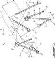
Figure 2 is an isometric schematic view of a first mounting arrangement where the engine mass is depicted as a sphere having a roll axis and being supported by two forward links, two rearward links and two middle A-frame links. -
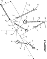
Figure 3 is a like isometric schematic view of a second mounting arrangement where the engine is supported by two forward links, two rearward links, two central roll constraint links and a rear axial constraint link. -
Figure 4 is a like isometric schematic view of a third mounting arrangement where compared toFigure 2 the two rearward links have been rotated 180 degrees about the roll axis. -
Figure 5 is a section view along line 5-5 ofFigure 2 showing segmented elastomeric bushings for restraining roll rotation and axial translation. -
Figure 1 shows an example aircraft 1 with arotary engine 2 driving apropeller 3. The present description relates to the mounting arrangement for mounting such arotary engine 2 to the aircraft structure using struts or links. WhileFig. 1 illustrates an airplane, it is understood that the mounting arrangement could also be used for helicopter installations. For instance, the mounting arrangement could be used to mount a compounded turboshaft engine including at least one rotary engine (e.g. A Wankel engine) compounding power with a turbine, to the structure of a helicopter. -
Figure 2 shows an isometric schematic view of a first mounting arrangement where the engine mass is depicted for clarity as asphere 4 having aroll axis 5, ayaw axis 15 and apitch axis 14 extending through the center ofgravity 6 of thesphere 4. Therotary engine 2 mass depicted as asphere 4 is supported on the aircraft structure by a front mount, a rear mount and an intermediate mount. - The front mount includes two non-parallel one-degree-of-freedom (1DOF) links 7 attached to either side of the
engine 2 at a same axial station. Likewise, the rear mount includes two non-parallel 1 DOF links 8 attached to either side of theengine 2 at a same axial station. The reaction axis of these links will extend through the link longitudinal axes. - The forward links 7 and rearward links 8 are arranged with their
reaction vectors 11 directed through theroll axis 5. Accordingly, the forward and rearward links 7, 8 do not constrain roll rotation about theroll axis 5 and do not constrain axial translation parallel to theroll axis 5. The forward and rearward links 7, 8 do constrain pitch rotation and yaw rotation. The forward and rearward links 7, 8 also constrain translation parallel to the pitch andyaw axes 14 ,15 (they resist vertical and lateral movements). The forward and rearward links 7, 8 have a high stiffness to restrict deflection of the engine. - In the example illustrated in
Figure 2 , the intermediate mount includes a pair ofA-frames 9 on each side of theengine 2 at a same axial station. Each A-frame 9 has atrunnion 10 at its apex. TheA-frames 9 restrain axial translation parallel to theroll axis 5 as well as translation along theyaw axis 15. The stiffness at each of these engine interfaces can be controlled using elastomeric isolators so that the stiffness along theyaw axis 15 is low and the axial stiffness alongroll axis 5 is high. TheA-frames 9 also constrain rotation about theroll axis 5. Thetrunnion 10 exerts a moment force to constrain roll rotation since thetrunnions 10 are disposed a distance "x" from theroll axis 5. - The A-frames will have reaction axes in the plane of the A-frame. These exert a "moment reaction" or vector that is laterally spaced from the center of gravity. Since the A-frame is a triangular structure with ball or pin joints at the ends, the resultant reaction forces/vectors exerted by the A-frame members would resolve to two orthogonal resultant reaction forces in the plane of the A-frame (i.e.: a plane defined by 3 points on the axes about which the pin ends rotate).
- It can be appreciated that lateral rigid body motion along the
pitch axis 14 is restricted by the forward and rearward links 7, 8. Axial rigid body motion along theroll axis 5 is restricted by axial reactions of theintermediate A-frames 9. Vertical rigid body motion alongyaw axis 15 is restricted by alllinks 7, 8 and 9, but is dominated by the stiffer forward and rearward links 7, 8. Rotation about theroll axis 5 is only resisted by vertical reactions of the 2intermediate mount A-frames 9. Rotation about thepitch axis 14 is predominantly resisted by the forward and rearward mount planes. Rotation about theyaw axis 15 is resisted at all mounts. This exemplary mount system contains a single DOF redundancy in that the system continues to restrict all degrees of freedom with any single link failed. - The embodiment shown in
Fig. 2 can be described as 8 1DOF links arranged in a 1-1-2-2-1-1 configuration in order to decouple the torque roll mode from other degrees of freedom. This allows the stiffness in the alternating torque direction to remain low while restricting other degrees of freedom in a stiff manner. The result is low vibratory force transmission through the mounts while maintaining low deflections under high g loading. This arrangement can be used on any engine with high alternating torques which requires low vibratory force transmission and low deflection under g loading. The reaction axis of these links will extend through the link longitudinal axes. -
Figure 3 shows a second example mounting arrangement where thetrunnion 10 is supported by aroll link 12. Axial translation is constrained byaxial link 13. By isolating the roll constraint from the other constraints, the mounting arrangement permits use of a relatively high mounting stiffness to restrict deflection of the engine and a relatively low mounting stiffness to restrict roll rotation about theroll axis 5. For example, elastomeric bushings of the required low mounting stiffness can be used in thetrunnions 10 whereas elastomeric bushings of the required high mounting stiffness can be used in the connection of thelinks 7, 8 and 13. The reaction axis of theroll link 12 will extend through the link longitudinal axes. -
Figure 4 shows a third mounting arrangement where the two rearward links 8 have been rotated 180 degrees about theroll axis 5. The links 7, 8 can be rotated in a mounting plane about theroll axis 5 provided that theirreactions 11 remain passing through theroll axis 5 which enables the engine to be mounted from below, from above or from one side. - In at least some of the arrangements, the low mounting stiffness for roll constraint remains decoupled from the other constraints having high mounting stiffness. In this manner, the tendency of the rotary engine to exert alternating roll torque forces on the supporting aircraft structure can be isolated with a low mounting stiffness bushing while high mounting stiffness restraints can be provided to limit deflection, pitch rotation and yaw rotation. Isolation is achieved by positioning the resonant frequency well below the excitation frequency, in a particular case by using a low stiffness in the torque roll axis. The mounting arrangement can be used on a rotary engine with high alternating roll torque forces which require low vibratory force transmission while retaining low deflection under g loading in flight. Further if any single link fails, the mounting arrangement continues to restrict all degrees of freedom providing a redundancy.
- Referring back to
Figure 3 , an example mounting arrangement is shown where restriction of roll rotation and axial translation are clearly separated. Accordingly, the roll restraint (rolllink 12 and trunnion 10) can provide a low stiffness independent of the high stiffness restraints of axial translation, pitch rotation, yaw rotation and linear translation in all directions. -
Figure 3 shows mounting arrangement for mounting therotary engine 2 to the aircraft structure 1 withlinks sphere 4 with a center ofgravity 6 through which theroll axis 5 passes. The engine mass has a three orthogonal axes all passing through the engine center ofgravity 6 namely: aroll axis 5 ; apitch axis 14; and ayaw axis 15. - A forward constraint is arranged in a plane orthogonal to the
roll axis 5. The forward constraint includes two non-parallel one-degree-of-freedom forward links 7 each having adistal end 16 adapted to be mounted to the aircraft structure and aproximal end 17 adapted to be mounted to the exterior of the rotary engine. The proximal ends 17 can include an elastomeric bushing having a high stiffness to resist deflection of the engine. Each forward link 7 has areaction axis 11 passing through theroll axis 5 and passing through the proximal and distal ends 17, 16 of the forward link 7. - In a like manner, a rearward constraint is arranged in a plane orthogonal to the
roll axis 5. The rearward constraint includes two non-parallel one-degree-of-freedom rearward links 8 each having adistal end 18 adapted to be mounted to the aircraft structure and aproximal end 19 adapted to be mounted to the exterior of the rotary engine. Each rearward link 8 has areaction axis 11 passing through theroll axis 5 and passing through the proximal and distal ends 19, 18 of the rearward link 8. The proximal ends 19 can include an elastomeric bushing having a high stiffness to resist deflection of the engine. - In the example of
Figure 3 , a separate one-degree-of-freedomaxial link 13 serves as an axial constraint having a reaction axis parallel to theroll axis 5. In the example shown the axial link is oriented at an angle with adistal end 20 adapted for mounting to the aircraft structure and aproximal end 21 disposed on theroll axis 5. Theproximal end 21 can include an elastomeric bushing having a high stiffness to resist axial deflection of the engine. - In
Figure 3 , the roll constraint is shown as a pair ofroll links 12 each with atrunnion 10. Thedistal end 22 of theroll link 12 is secured to the aircraft structure and exerts a moment reaction to restrain rotation about theroll axis 5. Thetrunnion 10 is mounted to the engine at a transverse distance "x" from theroll axis 5. The forward links 7, rearward links 8 andaxial link 13 have an elastomeric bushing with a relatively high mounting stiffness, and thetrunnion 10 on theroll link 12 has a relatively low mounting stiffness. Accordingly, the restraint of roll rotation about the roll axis is separate from other restraints and transmission of torque to the aircraft structure can be dampened with a lower stiffness. - Stated generally, the roll constraint comprises a one-degree-of-
freedom roll link 12 having adistal end 22 adapted to be mounted to the aircraft structure and a proximal end with atrunnion 10 adapted to be mounted to the rotary engine. Theroll link 12 has a reaction axis that is non-parallel to theroll axis 5 and spaced a transverse distance "x" from theroll axis 5. The roll constraint includes an opposing pair of the one-degree-of-freedom roll links 12 disposed on opposing sides of theroll axis 5 to decouple the torque roll degree of freedom. - In the examples of
Figures 2 and4 , the axial restraint function of theaxial link 13 and roll restraint function of theroll link 12 are combined in anA-frame 9. The combined axial constraint and the roll constraint is formed as an A-frame having two non-parallel one-degree-of-freedomcentral links 24. Eachcentral link 24 has adistal end 25 adapted to be mounted to the aircraft structure. The distal ends 25 are spaced apart an axial distance "y" and the angular orientation provides for axial restraint. The proximal end of thecentral links 24 support thetrunnion 10 which is adapted to be mounted to the rotary engine. The proximal ends of thecentral links 24 are joined at thetransverse trunnion 10. - With reference to
Figure 5 , thetransverse trunnion 10 restrains motion in the axial direction and in the roll rotation direction with an elastomeric bushing having anaxial segment 26 defining the axial constraint with a high mounting stiffness and aradial segment 27 defining the roll constraint having a low mounting stiffness. An opposing pair ofA-frames 9 is disposed on opposing sides of theroll axis 5. - In the examples shown, in
Figures 2 and3 , the forward links 7 and the rearward links 8 are disposed on the same side of theroll axis 5 as the A-frames 9. However as indicated inFigure 4 , the orientation of the links 7, 8 and A-frame 9 could be rotated about theroll axis 5 for accommodating various engine mounting arrangements. - In accordance with at least one embodiment, there is provided an aircraft mount for a rotary engine having one degree of freedom links arranged to (i) decouple mounting degrees of freedom so that engine torque excitation will not cause displacements in any degree of freedom other than rotation about the roll axis, and (ii) restrain torque roll degree of freedom in a soft manner to isolate the aircraft structure from the engine torque excitation, and (iii) restrain all other degrees of freedom in a stiff manner to prevent high engine displacements.
- The above description is meant to be exemplary only, and one skilled in the relevant arts will recognize that changes may be made to the embodiments described without departing from the scope of the invention disclosed. The present disclosure may be embodied in other specific forms without departing from the subject matter of the claims. The present disclosure is intended to cover and embrace all suitable changes in technology. Modifications which fall within the scope of the present invention will be apparent to those skilled in the art, in light of a review of this disclosure, and such modifications are intended to fall within the appended claims. Also, the scope of the claims should not be limited by the preferred embodiments set forth in the examples, but should be given the broadest interpretation consistent with the description as a whole.
Claims (15)
- An aircraft engine assembly comprising:a rotary engine (2) having a roll axis (5), a pitch axis (14) and a yaw axis (15), each axis extending through a center of gravity (6) of the rotary engine (2),a first set of one-degree-of-freedom links (7,8) mounted to a first side and a second side of the rotary engine (2), the first set of one-degree-of-freedom links (7,8) having a distal end (16,18) configured to be mounted to an aircraft (1) and a proximal end (17,19) mounted to the rotary engine (2), the first set of one-degree-of-freedom links (7,8) positioned relative to the rotary engine (2) to have respective reaction axes (11) passing through the roll axis (5); anda second set of links (12;9) having a distal end (20;25) configured to be mounted to the aircraft (1) and a proximal end (21) mounted to the rotary engine (2), the second set of links (12;9) positioned relative to the rotary engine (2) to have respective reaction axes transversally spaced-apart from the roll axis (5).
- The aircraft engine assembly according to claim 1, wherein the first set of one-degree-of-freedom links (7,8) has a first mounting stiffness, and the second set of links (12;9) has a second mounting stiffness, wherein the second mounting stiffness is less than the first mounting stiffness.
- The aircraft engine assembly according to claim 1, wherein the first set of one-degree-of-freedom links (7,8) include a pair of forward links (7) and a pair of rearward links (8) and an axial constraint link (13) has a reaction axis (11) parallel to the roll axis (5), wherein the forward links (7), the rearward links (8) and the axial constraint link (13) have a first mounting stiffness, and the second set of links (12;9) have a second mounting stiffness, wherein the second mounting stiffness is less than the first mounting stiffness.
- The aircraft engine assembly according to any preceding claim, wherein the second set of links (12) comprises a pair of one-degree-of-freedom roll links (12), the roll links (12) having reaction axes (11) non-parallel to the roll axis (5) and spaced a transverse distance X from the roll axis (5).
- The aircraft engine assembly according to claim 4, wherein the pair of one-degree-of-freedom roll links (12) is an opposing pair of said one-degree-of-freedom roll links (12) disposed on opposing sides of the roll axis (5).
- The aircraft engine assembly according to any of claims 1 to 3, wherein the second set of links (9) comprises a pair of A-frames (9) each having two non-parallel one-degree-of-freedom links (24), each non-parallel one-degree-of-freedom link (24) having a distal end (25) configured to be mounted to the aircraft spaced apart an axial distance and a proximal end mounted to the rotary engine (2).
- The aircraft engine assembly according to claim 6 wherein the proximal ends of the non-parallel one-degree-of-freedom links (24) of the A-frame (9) are joined at a trunnion (10), optionally the trunnion (10) includes an axial segment (26) defining the axial constraint having the first mounting stiffness and a radial segment (27) defining the roll constraint having the second mounting stiffness.
- The aircraft engine assembly according to claim 6 or 7 wherein the pair of A-frames (9) is an opposing pair of said A-frames (9) disposed on opposing sides of the roll axis (5).
- A method of mounting a rotary engine (2) to an aircraft structure, wherein the engine (2) has a three orthogonal axes comprising: a roll axis (5); a pitch axis (14); and a yaw axis (15), each axis extending through a center of gravity of the rotary engine (2), the method comprising:mounting a forward portion of the engine (2) to the aircraft structure with an opposing pair of non-parallel one-degree-of-freedom forward links (7) having a reaction axis (11) passing through the roll axis (5);mounting a rearward portion of the engine (2) to the aircraft structure with an opposing pair of non-parallel one-degree-of-freedom rearward links (8) having a reaction axis (11) passing through the roll axis (5);axially constraining the engine (2) with an axial constraint having a reaction axis (11) parallel to the roll axis (5); androtationally constraining the engine with a roll constraint having a moment reaction about the roll axis (5);wherein the forward links, rearward links and axial constraint have a first mounting stiffness, and the roll constraint has a second mounting stiffness, wherein the second mounting stiffness is less than the first mounting stiffness.
- The method according to claim 9 wherein the engine is rotationally constrained about the roll axis (5) using a one-degree-of-freedom roll link having a reaction axis non-parallel to the roll axis (5) and spaced a transverse distance from the roll axis (5).
- The method according to claim 9 wherein the engine is rotationally constrained about the roll axis (5) and axially constrained parallel to the roll axis (5) using a pair of opposing A-frames (9) disposed on opposing sides of the roll axis (5).
- The method according to claim 11, wherein the A-frames (9) have two said one-degree-of-freedom roll links joined at a transverse trunnion (10), optionally the trunnion (10) includes an axial segment defining the axial constraint having the first mounting stiffness and a radial segment defining the roll constraint having the second mounting stiffness
- An aircraft mount for a rotary engine (2) comprising:an opposing pair of non-parallel one-degree-of-freedom forward links attached to a forward portion of the rotary engine and an opposing pair of non-parallel one-degree-of-freedom rearward links attached to a rearward portion of the rotary engine, the forward and rearward links having respective reaction axes passing through a torque roll axis (5) of the rotary engine; andan A-frame link (9) on each side of the engine between the forward and rearward links, the A-frame link (9) oriented with a reaction axis transversely spaced apart from the torque roll axis, the reaction axis of the A-frame link (9) being non-parallel to the torque roll axis (5) and configured to restrain axial and roll movement wherein the roll movement is restrained with a roll constraint of roll stiffness lower than an axial stiffness of an axial constraint and lower than a link stiffness of the non-parallel one-degree-of-freedom forward and rearward links (7,8).
- The aircraft mount according to claim 13 wherein the A-frame link (9) includes a trunnion (10) mounted to the engine (2).
- The aircraft mount according to claim 14 wherein the trunnion (10) includes an axial segment (26) defining the axial constraint having the axial stiffness and a radial segment (27) defining the roll constraint having the roll stiffness.
Applications Claiming Priority (1)
| Application Number | Priority Date | Filing Date | Title |
|---|---|---|---|
| US16/415,308 US11214377B2 (en) | 2019-05-17 | 2019-05-17 | Mount arrangement for torque roll vibration isolation |
Publications (2)
| Publication Number | Publication Date |
|---|---|
| EP3738885A1 true EP3738885A1 (en) | 2020-11-18 |
| EP3738885B1 EP3738885B1 (en) | 2023-11-15 |
Family
ID=70740560
Family Applications (1)
| Application Number | Title | Priority Date | Filing Date |
|---|---|---|---|
| EP20175282.1A Active EP3738885B1 (en) | 2019-05-17 | 2020-05-18 | Mount arrangement for torque roll vibration isolation |
Country Status (6)
| Country | Link |
|---|---|
| US (1) | US11214377B2 (en) |
| EP (1) | EP3738885B1 (en) |
| CN (1) | CN111942599B (en) |
| CA (1) | CA3081523A1 (en) |
| ES (1) | ES2967791T3 (en) |
| PL (1) | PL3738885T3 (en) |
Citations (4)
| Publication number | Priority date | Publication date | Assignee | Title |
|---|---|---|---|---|
| US2175999A (en) * | 1937-07-23 | 1939-10-10 | Wright Aeronautical Corp | Flexible engine mount |
| US5443229A (en) * | 1993-12-13 | 1995-08-22 | General Electric Company | Aircraft gas turbine engine sideways mount |
| US20030010866A1 (en) * | 1999-06-30 | 2003-01-16 | Wilksch Mark Conrad | Aircraft engine mounting |
| EP1866203A2 (en) * | 2005-04-04 | 2007-12-19 | Lord Corporation | Aircraft auxiliary power unit suspension system for isolating an aircraft auxiliary power unit |
Family Cites Families (11)
| Publication number | Priority date | Publication date | Assignee | Title |
|---|---|---|---|---|
| GB2303884B (en) | 1995-04-13 | 1999-07-14 | Rolls Royce Plc | A mounting for coupling a turbofan gas turbine engine to an aircraft structure |
| US6328293B1 (en) * | 1998-09-18 | 2001-12-11 | Lord Corporation | Multi-linkage suspension system including outboard isolators |
| GB2375513B (en) * | 2001-05-19 | 2005-03-23 | Rolls Royce Plc | A mounting arrangement for a gas turbine engine |
| GB201017303D0 (en) | 2010-10-14 | 2010-11-24 | Rolls Royce Plc | Support structure |
| FR2994942B1 (en) * | 2012-09-06 | 2015-08-07 | Airbus Operations Sas | LATERAL PROPULSIVE ASSEMBLY FOR AIRCRAFT COMPRISING A SUPPORT ARM OF A TURBOMOTEUR. |
| CN107429614B (en) * | 2015-02-20 | 2020-03-10 | 普拉特-惠特尼加拿大公司 | Composite engine assembly with mounting cage |
| US10408123B2 (en) * | 2015-02-20 | 2019-09-10 | Pratt & Whitney Canada Corp. | Engine assembly with modular compressor and turbine |
| US9879591B2 (en) * | 2015-02-20 | 2018-01-30 | Pratt & Whitney Canada Corp. | Engine intake assembly with selector valve |
| EP3344544B1 (en) * | 2015-09-04 | 2022-07-06 | LORD Corporation | Anti-torque aft-mounting systems, devices, and methods for turboprop/turboshaft engines |
| US20210284348A1 (en) * | 2016-08-08 | 2021-09-16 | Lord Corporation | Mounting systems, devices, and methods for aircraft engines |
| US10745142B2 (en) * | 2018-02-19 | 2020-08-18 | Pratt & Whitney Canada Corp. | Aircraft with wheel well between cooling duct outlets |
-
2019
- 2019-05-17 US US16/415,308 patent/US11214377B2/en active Active
-
2020
- 2020-05-06 CA CA3081523A patent/CA3081523A1/en active Pending
- 2020-05-15 CN CN202010413719.3A patent/CN111942599B/en active Active
- 2020-05-18 ES ES20175282T patent/ES2967791T3/en active Active
- 2020-05-18 PL PL20175282.1T patent/PL3738885T3/en unknown
- 2020-05-18 EP EP20175282.1A patent/EP3738885B1/en active Active
Patent Citations (4)
| Publication number | Priority date | Publication date | Assignee | Title |
|---|---|---|---|---|
| US2175999A (en) * | 1937-07-23 | 1939-10-10 | Wright Aeronautical Corp | Flexible engine mount |
| US5443229A (en) * | 1993-12-13 | 1995-08-22 | General Electric Company | Aircraft gas turbine engine sideways mount |
| US20030010866A1 (en) * | 1999-06-30 | 2003-01-16 | Wilksch Mark Conrad | Aircraft engine mounting |
| EP1866203A2 (en) * | 2005-04-04 | 2007-12-19 | Lord Corporation | Aircraft auxiliary power unit suspension system for isolating an aircraft auxiliary power unit |
Also Published As
| Publication number | Publication date |
|---|---|
| US20200361616A1 (en) | 2020-11-19 |
| US11214377B2 (en) | 2022-01-04 |
| ES2967791T3 (en) | 2024-05-03 |
| CN111942599A (en) | 2020-11-17 |
| CN111942599B (en) | 2024-10-29 |
| PL3738885T3 (en) | 2024-04-02 |
| EP3738885B1 (en) | 2023-11-15 |
| CA3081523A1 (en) | 2020-11-17 |
Similar Documents
| Publication | Publication Date | Title |
|---|---|---|
| CN104968566B (en) | Device for holding tanks in aircraft | |
| CN108349592B (en) | Reactive torque aft frame system, apparatus and method for a turboprop/turboshaft engine | |
| EP1238906B1 (en) | Multi-bladed tail rotor hub design for Coriolis relief | |
| US12291340B2 (en) | Propulsion unit with propeller and electric motor comprising an adapted primary structure, and aircraft having at least one such propulsion unit | |
| US4135856A (en) | Rotor blade retention system | |
| US20200262549A1 (en) | Vibration Isolation Systems for Advancing Blade Concept Rotorcraft | |
| US6679455B2 (en) | Pointing device and an onboard pointing system | |
| US20150125300A1 (en) | Rotor hub for a rotorcraft | |
| US10654558B2 (en) | Rotor hub with enforced collective coning | |
| KR20150000411A (en) | Rotor system of a rotary wing aircraft | |
| EP0449531B1 (en) | Rotors | |
| ES2646128T3 (en) | Modular rotor hub system of rotor aircraft | |
| US12291341B2 (en) | Compact electric propulsion unit comprising a statically determinate engine mount, and aircraft comprising at least one such electric propulsion unit | |
| EP3738885B1 (en) | Mount arrangement for torque roll vibration isolation | |
| US9902496B2 (en) | Multi-directional elastomeric dampened ball joint assembly | |
| US3163378A (en) | Rotary wing aircraft pylon mounting | |
| US6871820B2 (en) | Aircraft engine mounting | |
| US3208217A (en) | Turbine engine and gearbox mounting arrangement | |
| US4645423A (en) | Tension/compression rod arrangement for damping helicopter rotor blade oscillations | |
| CA3055737C (en) | An attachment for suspending aircraft engine | |
| EP1383680A1 (en) | Dual trunnion hub-to-mast assembly | |
| US11691723B2 (en) | Rotor assembly with static mast and pivoting rotor hub | |
| US7867096B2 (en) | Joint for tiltrotor hubs | |
| US20200398976A1 (en) | Mount Systems for Pylon Assemblies with Coaxial Rotors | |
| US7618007B1 (en) | Force balancing actuator |
Legal Events
| Date | Code | Title | Description |
|---|---|---|---|
| PUAI | Public reference made under article 153(3) epc to a published international application that has entered the european phase |
Free format text: ORIGINAL CODE: 0009012 |
|
| STAA | Information on the status of an ep patent application or granted ep patent |
Free format text: STATUS: THE APPLICATION HAS BEEN PUBLISHED |
|
| AK | Designated contracting states |
Kind code of ref document: A1 Designated state(s): AL AT BE BG CH CY CZ DE DK EE ES FI FR GB GR HR HU IE IS IT LI LT LU LV MC MK MT NL NO PL PT RO RS SE SI SK SM TR |
|
| AX | Request for extension of the european patent |
Extension state: BA ME |
|
| STAA | Information on the status of an ep patent application or granted ep patent |
Free format text: STATUS: REQUEST FOR EXAMINATION WAS MADE |
|
| 17P | Request for examination filed |
Effective date: 20210518 |
|
| RBV | Designated contracting states (corrected) |
Designated state(s): AL AT BE BG CH CY CZ DE DK EE ES FI FR GB GR HR HU IE IS IT LI LT LU LV MC MK MT NL NO PL PT RO RS SE SI SK SM TR |
|
| STAA | Information on the status of an ep patent application or granted ep patent |
Free format text: STATUS: EXAMINATION IS IN PROGRESS |
|
| 17Q | First examination report despatched |
Effective date: 20211007 |
|
| GRAP | Despatch of communication of intention to grant a patent |
Free format text: ORIGINAL CODE: EPIDOSNIGR1 |
|
| STAA | Information on the status of an ep patent application or granted ep patent |
Free format text: STATUS: GRANT OF PATENT IS INTENDED |
|
| INTG | Intention to grant announced |
Effective date: 20230525 |
|
| GRAS | Grant fee paid |
Free format text: ORIGINAL CODE: EPIDOSNIGR3 |
|
| GRAA | (expected) grant |
Free format text: ORIGINAL CODE: 0009210 |
|
| STAA | Information on the status of an ep patent application or granted ep patent |
Free format text: STATUS: THE PATENT HAS BEEN GRANTED |
|
| AK | Designated contracting states |
Kind code of ref document: B1 Designated state(s): AL AT BE BG CH CY CZ DE DK EE ES FI FR GB GR HR HU IE IS IT LI LT LU LV MC MK MT NL NO PL PT RO RS SE SI SK SM TR |
|
| REG | Reference to a national code |
Ref country code: CH Ref legal event code: EP Ref country code: GB Ref legal event code: FG4D |
|
| REG | Reference to a national code |
Ref country code: DE Ref legal event code: R079 Ref document number: 602020020957 Country of ref document: DE Free format text: PREVIOUS MAIN CLASS: B64D0027260000 Ipc: B64D0027400000 |
|
| REG | Reference to a national code |
Ref country code: DE Ref legal event code: R096 Ref document number: 602020020957 Country of ref document: DE |
|
| REG | Reference to a national code |
Ref country code: IE Ref legal event code: FG4D |
|
| REG | Reference to a national code |
Ref country code: LT Ref legal event code: MG9D |
|
| REG | Reference to a national code |
Ref country code: NL Ref legal event code: MP Effective date: 20231115 |
|
| PG25 | Lapsed in a contracting state [announced via postgrant information from national office to epo] |
Ref country code: GR Free format text: LAPSE BECAUSE OF FAILURE TO SUBMIT A TRANSLATION OF THE DESCRIPTION OR TO PAY THE FEE WITHIN THE PRESCRIBED TIME-LIMIT Effective date: 20240216 |
|
| PG25 | Lapsed in a contracting state [announced via postgrant information from national office to epo] |
Ref country code: IS Free format text: LAPSE BECAUSE OF FAILURE TO SUBMIT A TRANSLATION OF THE DESCRIPTION OR TO PAY THE FEE WITHIN THE PRESCRIBED TIME-LIMIT Effective date: 20240315 |
|
| PG25 | Lapsed in a contracting state [announced via postgrant information from national office to epo] |
Ref country code: LT Free format text: LAPSE BECAUSE OF FAILURE TO SUBMIT A TRANSLATION OF THE DESCRIPTION OR TO PAY THE FEE WITHIN THE PRESCRIBED TIME-LIMIT Effective date: 20231115 |
|
| REG | Reference to a national code |
Ref country code: AT Ref legal event code: UEP Ref document number: 1631553 Country of ref document: AT Kind code of ref document: T Effective date: 20231115 |
|
| PG25 | Lapsed in a contracting state [announced via postgrant information from national office to epo] |
Ref country code: NL Free format text: LAPSE BECAUSE OF FAILURE TO SUBMIT A TRANSLATION OF THE DESCRIPTION OR TO PAY THE FEE WITHIN THE PRESCRIBED TIME-LIMIT Effective date: 20231115 |
|
| PG25 | Lapsed in a contracting state [announced via postgrant information from national office to epo] |
Ref country code: NL Free format text: LAPSE BECAUSE OF FAILURE TO SUBMIT A TRANSLATION OF THE DESCRIPTION OR TO PAY THE FEE WITHIN THE PRESCRIBED TIME-LIMIT Effective date: 20231115 Ref country code: LT Free format text: LAPSE BECAUSE OF FAILURE TO SUBMIT A TRANSLATION OF THE DESCRIPTION OR TO PAY THE FEE WITHIN THE PRESCRIBED TIME-LIMIT Effective date: 20231115 Ref country code: IS Free format text: LAPSE BECAUSE OF FAILURE TO SUBMIT A TRANSLATION OF THE DESCRIPTION OR TO PAY THE FEE WITHIN THE PRESCRIBED TIME-LIMIT Effective date: 20240315 Ref country code: GR Free format text: LAPSE BECAUSE OF FAILURE TO SUBMIT A TRANSLATION OF THE DESCRIPTION OR TO PAY THE FEE WITHIN THE PRESCRIBED TIME-LIMIT Effective date: 20240216 Ref country code: BG Free format text: LAPSE BECAUSE OF FAILURE TO SUBMIT A TRANSLATION OF THE DESCRIPTION OR TO PAY THE FEE WITHIN THE PRESCRIBED TIME-LIMIT Effective date: 20240215 Ref country code: PT Free format text: LAPSE BECAUSE OF FAILURE TO SUBMIT A TRANSLATION OF THE DESCRIPTION OR TO PAY THE FEE WITHIN THE PRESCRIBED TIME-LIMIT Effective date: 20240315 |
|
| REG | Reference to a national code |
Ref country code: ES Ref legal event code: FG2A Ref document number: 2967791 Country of ref document: ES Kind code of ref document: T3 Effective date: 20240503 |
|
| PG25 | Lapsed in a contracting state [announced via postgrant information from national office to epo] |
Ref country code: SE Free format text: LAPSE BECAUSE OF FAILURE TO SUBMIT A TRANSLATION OF THE DESCRIPTION OR TO PAY THE FEE WITHIN THE PRESCRIBED TIME-LIMIT Effective date: 20231115 Ref country code: RS Free format text: LAPSE BECAUSE OF FAILURE TO SUBMIT A TRANSLATION OF THE DESCRIPTION OR TO PAY THE FEE WITHIN THE PRESCRIBED TIME-LIMIT Effective date: 20231115 Ref country code: NO Free format text: LAPSE BECAUSE OF FAILURE TO SUBMIT A TRANSLATION OF THE DESCRIPTION OR TO PAY THE FEE WITHIN THE PRESCRIBED TIME-LIMIT Effective date: 20240215 Ref country code: LV Free format text: LAPSE BECAUSE OF FAILURE TO SUBMIT A TRANSLATION OF THE DESCRIPTION OR TO PAY THE FEE WITHIN THE PRESCRIBED TIME-LIMIT Effective date: 20231115 Ref country code: HR Free format text: LAPSE BECAUSE OF FAILURE TO SUBMIT A TRANSLATION OF THE DESCRIPTION OR TO PAY THE FEE WITHIN THE PRESCRIBED TIME-LIMIT Effective date: 20231115 |
|
| PG25 | Lapsed in a contracting state [announced via postgrant information from national office to epo] |
Ref country code: DK Free format text: LAPSE BECAUSE OF FAILURE TO SUBMIT A TRANSLATION OF THE DESCRIPTION OR TO PAY THE FEE WITHIN THE PRESCRIBED TIME-LIMIT Effective date: 20231115 |
|
| PG25 | Lapsed in a contracting state [announced via postgrant information from national office to epo] |
Ref country code: SK Free format text: LAPSE BECAUSE OF FAILURE TO SUBMIT A TRANSLATION OF THE DESCRIPTION OR TO PAY THE FEE WITHIN THE PRESCRIBED TIME-LIMIT Effective date: 20231115 |
|
| PG25 | Lapsed in a contracting state [announced via postgrant information from national office to epo] |
Ref country code: SM Free format text: LAPSE BECAUSE OF FAILURE TO SUBMIT A TRANSLATION OF THE DESCRIPTION OR TO PAY THE FEE WITHIN THE PRESCRIBED TIME-LIMIT Effective date: 20231115 Ref country code: SK Free format text: LAPSE BECAUSE OF FAILURE TO SUBMIT A TRANSLATION OF THE DESCRIPTION OR TO PAY THE FEE WITHIN THE PRESCRIBED TIME-LIMIT Effective date: 20231115 Ref country code: RO Free format text: LAPSE BECAUSE OF FAILURE TO SUBMIT A TRANSLATION OF THE DESCRIPTION OR TO PAY THE FEE WITHIN THE PRESCRIBED TIME-LIMIT Effective date: 20231115 Ref country code: EE Free format text: LAPSE BECAUSE OF FAILURE TO SUBMIT A TRANSLATION OF THE DESCRIPTION OR TO PAY THE FEE WITHIN THE PRESCRIBED TIME-LIMIT Effective date: 20231115 Ref country code: DK Free format text: LAPSE BECAUSE OF FAILURE TO SUBMIT A TRANSLATION OF THE DESCRIPTION OR TO PAY THE FEE WITHIN THE PRESCRIBED TIME-LIMIT Effective date: 20231115 |
|
| REG | Reference to a national code |
Ref country code: DE Ref legal event code: R097 Ref document number: 602020020957 Country of ref document: DE |
|
| PLBE | No opposition filed within time limit |
Free format text: ORIGINAL CODE: 0009261 |
|
| STAA | Information on the status of an ep patent application or granted ep patent |
Free format text: STATUS: NO OPPOSITION FILED WITHIN TIME LIMIT |
|
| 26N | No opposition filed |
Effective date: 20240819 |
|
| PG25 | Lapsed in a contracting state [announced via postgrant information from national office to epo] |
Ref country code: SI Free format text: LAPSE BECAUSE OF FAILURE TO SUBMIT A TRANSLATION OF THE DESCRIPTION OR TO PAY THE FEE WITHIN THE PRESCRIBED TIME-LIMIT Effective date: 20231115 |
|
| PG25 | Lapsed in a contracting state [announced via postgrant information from national office to epo] |
Ref country code: SI Free format text: LAPSE BECAUSE OF FAILURE TO SUBMIT A TRANSLATION OF THE DESCRIPTION OR TO PAY THE FEE WITHIN THE PRESCRIBED TIME-LIMIT Effective date: 20231115 |
|
| PG25 | Lapsed in a contracting state [announced via postgrant information from national office to epo] |
Ref country code: MC Free format text: LAPSE BECAUSE OF FAILURE TO SUBMIT A TRANSLATION OF THE DESCRIPTION OR TO PAY THE FEE WITHIN THE PRESCRIBED TIME-LIMIT Effective date: 20231115 |
|
| PG25 | Lapsed in a contracting state [announced via postgrant information from national office to epo] |
Ref country code: LU Free format text: LAPSE BECAUSE OF NON-PAYMENT OF DUE FEES Effective date: 20240518 |
|
| PG25 | Lapsed in a contracting state [announced via postgrant information from national office to epo] |
Ref country code: MC Free format text: LAPSE BECAUSE OF FAILURE TO SUBMIT A TRANSLATION OF THE DESCRIPTION OR TO PAY THE FEE WITHIN THE PRESCRIBED TIME-LIMIT Effective date: 20231115 Ref country code: LU Free format text: LAPSE BECAUSE OF NON-PAYMENT OF DUE FEES Effective date: 20240518 |
|
| REG | Reference to a national code |
Ref country code: BE Ref legal event code: MM Effective date: 20240531 |
|
| PG25 | Lapsed in a contracting state [announced via postgrant information from national office to epo] |
Ref country code: IE Free format text: LAPSE BECAUSE OF NON-PAYMENT OF DUE FEES Effective date: 20240518 |
|
| PG25 | Lapsed in a contracting state [announced via postgrant information from national office to epo] |
Ref country code: BE Free format text: LAPSE BECAUSE OF NON-PAYMENT OF DUE FEES Effective date: 20240531 |
|
| PGFP | Annual fee paid to national office [announced via postgrant information from national office to epo] |
Ref country code: PL Payment date: 20250425 Year of fee payment: 6 Ref country code: DE Payment date: 20250423 Year of fee payment: 6 |
|
| PGFP | Annual fee paid to national office [announced via postgrant information from national office to epo] |
Ref country code: ES Payment date: 20250602 Year of fee payment: 6 Ref country code: GB Payment date: 20250423 Year of fee payment: 6 |
|
| PGFP | Annual fee paid to national office [announced via postgrant information from national office to epo] |
Ref country code: IT Payment date: 20250423 Year of fee payment: 6 |
|
| PGFP | Annual fee paid to national office [announced via postgrant information from national office to epo] |
Ref country code: FR Payment date: 20250423 Year of fee payment: 6 |
|
| PGFP | Annual fee paid to national office [announced via postgrant information from national office to epo] |
Ref country code: CH Payment date: 20250601 Year of fee payment: 6 |
|
| PGFP | Annual fee paid to national office [announced via postgrant information from national office to epo] |
Ref country code: AT Payment date: 20250424 Year of fee payment: 6 |
|
| PGFP | Annual fee paid to national office [announced via postgrant information from national office to epo] |
Ref country code: CZ Payment date: 20250429 Year of fee payment: 6 |
|
| PG25 | Lapsed in a contracting state [announced via postgrant information from national office to epo] |
Ref country code: CY Free format text: LAPSE BECAUSE OF FAILURE TO SUBMIT A TRANSLATION OF THE DESCRIPTION OR TO PAY THE FEE WITHIN THE PRESCRIBED TIME-LIMIT; INVALID AB INITIO Effective date: 20200518 |
|
| PG25 | Lapsed in a contracting state [announced via postgrant information from national office to epo] |
Ref country code: HU Free format text: LAPSE BECAUSE OF FAILURE TO SUBMIT A TRANSLATION OF THE DESCRIPTION OR TO PAY THE FEE WITHIN THE PRESCRIBED TIME-LIMIT; INVALID AB INITIO Effective date: 20200518 |
|
| PG25 | Lapsed in a contracting state [announced via postgrant information from national office to epo] |
Ref country code: FI Free format text: LAPSE BECAUSE OF FAILURE TO SUBMIT A TRANSLATION OF THE DESCRIPTION OR TO PAY THE FEE WITHIN THE PRESCRIBED TIME-LIMIT Effective date: 20231115 |
|
| P01 | Opt-out of the competence of the unified patent court (upc) registered |
Free format text: CASE NUMBER: UPC_APP_0000154_3738885/2026 Effective date: 20260105 |