EP3738702A1 - Drilling method for multi bit drilling machine and corresponding drilling machine using such method - Google Patents
Drilling method for multi bit drilling machine and corresponding drilling machine using such method Download PDFInfo
- Publication number
- EP3738702A1 EP3738702A1 EP20170809.6A EP20170809A EP3738702A1 EP 3738702 A1 EP3738702 A1 EP 3738702A1 EP 20170809 A EP20170809 A EP 20170809A EP 3738702 A1 EP3738702 A1 EP 3738702A1
- Authority
- EP
- European Patent Office
- Prior art keywords
- drilling
- bits
- extracted
- bit
- unit
- Prior art date
- Legal status (The legal status is an assumption and is not a legal conclusion. Google has not performed a legal analysis and makes no representation as to the accuracy of the status listed.)
- Granted
Links
Images

Classifications
-
- B—PERFORMING OPERATIONS; TRANSPORTING
- B23—MACHINE TOOLS; METAL-WORKING NOT OTHERWISE PROVIDED FOR
- B23B—TURNING; BORING
- B23B39/00—General-purpose boring or drilling machines or devices; Sets of boring and/or drilling machines
- B23B39/16—Drilling machines with a plurality of working-spindles; Drilling automatons
- B23B39/161—Drilling machines with a plurality of working-spindles; Drilling automatons with parallel work spindles
-
- B—PERFORMING OPERATIONS; TRANSPORTING
- B23—MACHINE TOOLS; METAL-WORKING NOT OTHERWISE PROVIDED FOR
- B23B—TURNING; BORING
- B23B35/00—Methods for boring or drilling, or for working essentially requiring the use of boring or drilling machines; Use of auxiliary equipment in connection with such methods
-
- B—PERFORMING OPERATIONS; TRANSPORTING
- B23—MACHINE TOOLS; METAL-WORKING NOT OTHERWISE PROVIDED FOR
- B23B—TURNING; BORING
- B23B39/00—General-purpose boring or drilling machines or devices; Sets of boring and/or drilling machines
- B23B39/16—Drilling machines with a plurality of working-spindles; Drilling automatons
- B23B39/24—Drilling machines with a plurality of working-spindles; Drilling automatons designed for program control
-
- G—PHYSICS
- G05—CONTROLLING; REGULATING
- G05B—CONTROL OR REGULATING SYSTEMS IN GENERAL; FUNCTIONAL ELEMENTS OF SUCH SYSTEMS; MONITORING OR TESTING ARRANGEMENTS FOR SUCH SYSTEMS OR ELEMENTS
- G05B19/00—Program-control systems
- G05B19/02—Program-control systems electric
- G05B19/18—Numerical control [NC], i.e. automatically operating machines, in particular machine tools, e.g. in a manufacturing environment, so as to execute positioning, movement or co-ordinated operations by means of program data in numerical form
- G05B19/402—Numerical control [NC], i.e. automatically operating machines, in particular machine tools, e.g. in a manufacturing environment, so as to execute positioning, movement or co-ordinated operations by means of program data in numerical form characterised by control arrangements for positioning, e.g. centring a tool relative to a hole in the workpiece, additional detection means to correct position
-
- B—PERFORMING OPERATIONS; TRANSPORTING
- B23—MACHINE TOOLS; METAL-WORKING NOT OTHERWISE PROVIDED FOR
- B23B—TURNING; BORING
- B23B2260/00—Details of constructional elements
- B23B2260/048—Devices to regulate the depth of cut
- B23B2260/0482—Depth controls, e.g. depth stops
-
- B—PERFORMING OPERATIONS; TRANSPORTING
- B23—MACHINE TOOLS; METAL-WORKING NOT OTHERWISE PROVIDED FOR
- B23B—TURNING; BORING
- B23B2260/00—Details of constructional elements
- B23B2260/128—Sensors
-
- G—PHYSICS
- G05—CONTROLLING; REGULATING
- G05B—CONTROL OR REGULATING SYSTEMS IN GENERAL; FUNCTIONAL ELEMENTS OF SUCH SYSTEMS; MONITORING OR TESTING ARRANGEMENTS FOR SUCH SYSTEMS OR ELEMENTS
- G05B2219/00—Program-control systems
- G05B2219/30—Nc systems
- G05B2219/37—Measurements
- G05B2219/37231—Tool used as touch probe, sensor
-
- G—PHYSICS
- G05—CONTROLLING; REGULATING
- G05B—CONTROL OR REGULATING SYSTEMS IN GENERAL; FUNCTIONAL ELEMENTS OF SUCH SYSTEMS; MONITORING OR TESTING ARRANGEMENTS FOR SUCH SYSTEMS OR ELEMENTS
- G05B2219/00—Program-control systems
- G05B2219/30—Nc systems
- G05B2219/37—Measurements
- G05B2219/37413—By conductivity, short circuit between tool, probe and metallic surface
-
- G—PHYSICS
- G05—CONTROLLING; REGULATING
- G05B—CONTROL OR REGULATING SYSTEMS IN GENERAL; FUNCTIONAL ELEMENTS OF SUCH SYSTEMS; MONITORING OR TESTING ARRANGEMENTS FOR SUCH SYSTEMS OR ELEMENTS
- G05B2219/00—Program-control systems
- G05B2219/30—Nc systems
- G05B2219/50—Machine tool, machine tool null till machine tool work handling
- G05B2219/50001—Multislides, multispindles with multitool turret for each
Definitions
- the present invention relates to a drilling method for multi bit drilling machine and relative drilling machine using such method.
- the invention relates to a method and a machine for making multiple holes with depth precision, through the use of automatic drilling machines provided with a plurality of drilling bits.
- wood panels, wood, plastic, fiberglass or similar panels are perforated through the use of automatic drilling machines.
- This operation is necessary, for example, in the manufacturing of furniture, in which several panels must be cut and drilled for subsequent assembly.
- These drilling machines can make a plurality of holes on the same panel simultaneously, thanks to the possibility of simultaneously using several drilling bits often (but not necessarily) arranged in series or in line.
- said holes are usually all substantially of the same size, made by the simultaneous use of drills having the same caliber and the same length.
- the drilling machines according to the prior art have mandrels, which can only assume two positions: an extracted position, in which they are active and capable of performing the drilling with the respective installed bit, and a retracted position, in which they are not able to carry out the drilling.
- this alignment difference can vary between a few tenths of a millimeter up to a few centimeters.
- the aforementioned misalignment can be particularly problematic if precision holes are required, which are necessary in various machining.
- checking the alignment carried out manually as mentioned above requires time, which entails the drilling machine to be stopped for potentially long times, thus causing an increase in production costs.
- a further object of the present invention is to provide an automatic drilling method, which does not require manual calibration of the bits by an operator.
- Another object of the present invention is to provide a drilling method, which does not depend on the initial position of the drilling bits.
- Still another object of the present invention is to provide a drilling method for panels which minimizes the downtime of the drilling machines.
- an object of the present invention is to provide an easy implementation and rapid execution method.
- the object of the present invention is to provide a system for the implementation of this method, which can be easily implemented within prior art machines.
- object of the present invention is to provide a system for the implementation of said method, which is economically advantageous, both as regards production and maintenance costs.
- said relative position among said drilling bits in said extracted or retracted position may be equal to the alignment difference along said movement direction, among each bit of said bits.
- each drilling bit in said extracted or retracted position may be detected with respect to the drill bit of a first of said extracted or retracted drilling bits, preferably the extracted or retracted bit whose drilling bits is closer to the surface of said panel.
- said panel may be arranged on a worktop, and said at least one movement direction may be perpendicular to said worktop.
- said detecting step B my further comprise the following sub-steps: B1. detecting the distance of each extracted bit from said worktop; B2. subtracting from each value obtained in the step B1 the thickness of said panel along said movement direction; and B3. adding the predetermined drilling depth value to each value obtained in step B2, so as to obtain movement values of said drilling unit during said step B.
- said drilling depth of said bits may be equal to each other.
- It is a second object of the invention a drilling machine for drilling panels comprising a drilling unit, movable along one direction of movement, and comprising a plurality of spindles, each capable of selectively switching from an extracted position to a retracted position and vice versa, and a plurality of drilling bits each fixed on one of the respective of said spindles, and a control unit, operationally connected to said drilling unit, to handle said drilling unit along said movement direction and to switch said spindles from said extracted position to said retracted position and vice versa, said drilling machine being characterized in that said control unit is configured to carry out the method according to any one of the preceding claims.
- said drilling machine may comprise a worktop for supporting said panels to be drilled.
- said drilling machine may comprise a measurement system.
- said measurement system may comprise a conductive plate, to be arranged in a reference position, at least one current generator, electrically connected to a respective drilling bit, said at least one current generator being capable of generating a reference current on command, a plurality of resistors, each series connected to said at least one generator, a detecting module, electrically connected to said conductive plate through a common knot and to each of said resistors, wherein said drilling unit is moved along said movement direction toward said conductive plate, so that, when each drilling bit touches said conductive plate, said at least one current generator generates a current and said detecting module detects the passage of said generated current passing through the respective resistor, so as to detect the relative position of said drilling unit, and said control unit passes said drilling bit from said extracted position to said retracted position.
- said measure system may comprise a load cell, to be arranged in a reference position, a detecting module, electrically connected to said load cell, wherein said drilling unit is moved along said movement direction to said load cell, so that, when said load cell detects a stress caused by each drilling bit, said load cell generates an electrical signal to said detecting module so as to detect the position of said drilling unit, and said control unit switches said drilling bit from said extracted position to said retracted position.
- said detecting module may be incorporated in said control unit.
- said conductive plate or said load cell is arranged on said worktop.
- said conductive plate or said load cell is incorporated in said worktop.
- It is further object of the present invention a computer program comprising instructions that, when the program is executed by a computer, cause the execution, by the computer, of the steps A-D of the method according to the invention.
- a drilling machine is observed, indicated as a whole with the numerical reference 1, for the simultaneous production of a plurality of holes F on a panel P, wherein said holes F all have a predetermined depth D.
- said drilling machine 1 or machine 1 comprises a control unit U, a drilling unit 2, having a plurality of spindles 41, 42, 43, and 44, and a plurality of drilling bits 51, 52, 53, and 54 for they are connected for drilling the panel P, and a worktop 3.
- Said control unit U is for example a computer.
- Said drilling unit 2 is operatively connected to said control unit U.
- said drilling unit 2 is movable on a vertical axis Z, in the present example perpendicular with respect to the underlying worktop 3, on which the panel P to be worked is arranged.
- said Z axis may be any direction of movement Z, and may also be non-perpendicular with respect to the worktop 3, on which the panel P to be worked is arranged.
- the drilling unit 2 can assume different height positions with respect to said worktop 3, so as to work panels P of different thickness and adjust the depth D of the holes F to be made on said panels P.
- the adjustment of the working height of said drilling unit 2 can take place with suitable pneumatic or hydraulic programmable means, controlled by said control unit U, to allow the exchange of the drilling bits 51, 52, 53, and 54, or for modifying the depth D of said holes F.
- Said plurality of spindles comprises in the present embodiment four spindles 41, 42, 43, and 44.
- the number of spindles can vary according to the drilling machine 1.
- Each spindle 41, 42, 43, and 44 can be installed on a respective support or stem, respectively indicated with 41', 42', 43', and 44', each movable between an extracted position and a retracted position, or each spindle 41, 42, 43, and 44 can be movable between an extracted position and a retracted position, without said supports 41', 42', 43', 44' being present, the operation of which will be better defined below.
- Said supports 41', 42', 43', and 44' and/or said spindles 41, 42, 43, 44 can be independently activated between them, so that they can be placed, if necessary, in an extracted or retracted position, manually selectable from an operator for each machining, or programmable, so as to automatically change during the machining of the panels P, as better explained below.
- the drilling machine 1 comprises four bits 51, 52, 53, and 54, one for each respective spindle 41, 42, 43, and 44.
- spindle in extracted position each spindle installed on a support in an extracted position, or each spindle, not associated with any stem, in an extracted position, and with the term “spindle in a retracted position” each spindle installed on a support in a retracted position or each spindle, not associated with any stem, in the retracted position.
- each bit coupled with a respective spindle in the extracted position will be indicated with the term “extracted bit” or “bit in the extracted position”, and with the term “retracted bit” or “bit in the retracted position” each bit coupled with a respective spindle in retracted position.
- each of said two or more extracted bits will, by means of the described method, simultaneously produce a respective hole F of depth D on the panel P.
- each of said two or more bits will pass into the retracted position after the realization of said hole F of depth D. This passage can take place simultaneously (when two or more bits are exactly aligned) or, more generally, in sequence.
- each measured offset ⁇ 32 and ⁇ 34 a respective value ⁇ 2 and ⁇ 4 equal to the difference between the depth D2 and D3 associated with the respective hole F of each further extracted bit 52 or 54 and the depth D3 of the hole F, associated with said reference bit 53.
- These new offset values will be the offset values to be ordered from the smallest to the largest during the operation of said drilling machine 1.
- all the bits 52, 53, 54 which, in the configuration shown in figures 1A and 1B , are initially in the extracted position, must have a length greater than the depth D of the holes F to be made on the panels P, and the height of the panel with respect to said Z axis has to be determined or determinable.
- said machine 1 can comprise a measuring system 6 for measuring said offsets among said extracted bits 51, 53, 54.
- said measuring system 6 comprises a conductive plate 7, a detecting module 8, a plurality of impedances 91, 92, 93, and 94, and a plurality of current generators 101, 102, 103, 104.
- Said conductive plate 7 is in fact made of electrically conductive material.
- said conducting plate 7 rests on said worktop 3, and can have a negligible thickness with respect to the height of said panel P with reference to said axis Z.
- the detecting module 8 is electrically connected to said conductive plate 7 on a common node 81.
- the detecting module 8 can be a functional part of said control unit U of said drilling machine 1, or it can be controlled by it.
- each one of said impedances 91, 92, 93, and 94 which are resistors in the present case, are each connected to said detecting module 8, and in series to a respective current generator 101, 102, 103, 104.
- Each of said current generators 101, 102, 103, 104 is in turn electrically connected to a respective bit 51, 52, 53, 54.
- said impedances 91, 92, 93, and 94 can be connected, through a first common node, to a single current generator, which is in turn connected, through a second common node, to said bits 51, 52, 53, 54.
- Said connection between each current generator 101, 102, 103, 104, and the respective bit 51, 52, 53, 54 can be a removable type connection.
- said drilling unit 2 is first lowered according to the arrow A until the extracted bit 51, which in figure 2 is the closest to the conductive plate 7, comes into electrical contact with said conducting plate 7, closing the electrical circuit comprising said conducting plate 7 itself, said detecting module 8, said bit 51, the respective impedance 91 connected to said bit 51, and the current generator 101 thereof.
- the detecting module 8 detects the passage of current in the aforementioned circuit relating to the bit 51, and detects and stores the position of the drilling unit 2, with respect to said Z-axis with respect to said bit 51.
- Said bit 51 then passes from said extracted position to said retracted position.
- each support 41', 43', 44', whose position has been detected is passed from said retracted position to said extracted position, after the drilling unit 2 has been raised.
- said measuring system 6 can memorize the position of said drilling unit 2, with respect to said Z axis, whenever a point 51, 53, 54 in the extracted position touches said conducting plate 7 by closing the circuit, for example using as reference the initial position of said drilling unit 2, or the position of said drilling unit 2 when the first bit 51 touches said conducting plate 7.
- said measuring system can comprise a load cell, alternative to said conductive plate 7, and a detecting module.
- Said load cell (not shown in the figures), in fact, will generate an electrical signal towards said detection module when mechanically stressed, or when touched by said drilling points 51, 52, 53, 54.
- said conductive plate or said load cell can be integrated directly into said worktop 3.
- said measuring system 6 will be able to calculate the value of said offsets ⁇ ij , starting from said measured values and/or the relative lowering between each bit, whose position has been measured in subsequent surveys, possibly together with information that allow to identify the order in which said bits touched said conducting plate 7 or said load cell.
- said measuring system 6 can store the height of said drilling unit 2, with respect to said Z axis, when said reference bit 51 touches said conducting plate 7 or said load cell during the first detection, while in the following detections it can detect and store directly the relative lowering, with respect to the first or the previous detected bit, of said drilling unit 2 with respect to said Z axis, possibly together with the information that allows to identify the order in which said bits have touched said conductive plate 7 or said load cell.
- An example of a method for tracing the order in which said bits 51, 53, 54 have touched said conducting plate 7 or said load cell consists in saving the heights of said drilling unit 2 detected with respect to said Z axis in a single ordered vector.
- each element of said ordered vector can be associated with a particular support 41', 43', 44' in an extracted position, and it is sufficient to order said heights measured from the smallest to the largest, to trace the order in which said bits 51, 53, 54 have to pass from said extracted position to said retracted position.
- an operator can enter, as input values to said control unit U, the distance of each extracted tip from the panel P with respect to said Z-axis.
- a program internal to said control unit U will therefore be able to choose a reference bit and calculate the relative offsets, or it will be the operator himself to supply this information manually.
- the implementation of the drilling method comprises the following main steps, briefly described below.
- a first step 110 the position of said drilling bits 51, 52, 53, 54 is detected in said extracted position.
- step 120 the drilling unit 2 is moved along the direction of movement Z.
- a third control step 130 it is checked whether at least one extracted drill bit 51, 52, 53, 54 has made on the panel P the respective hole F of the respective drilling depth D, D1, D2, D3, D4. If said control step 130 is not verified, it returns to the second processing step 120. Else, if said third control step 130 is verified, step 140 is continued, in which the extracted tip 51, 52, 53, 54, which made said hole F, is retracted.
- a fifth control step 150 subsequent to said fourth step 140, it is checked whether there is at least one bit 51, 52, 53, 54 in the extracted position, and, if said fifth control step 150 is not verified, the drilling procedure is terminated, else, if said fifth control step 150 is verified, it returns to said second processing step 120.
- said first processing step 110 can comprise the following sub-steps:
- said first processing step 110 can also have as input the position of the panel P to be drilled.
- said first processing step 110 can comprise the following sub-steps:
- control sub-step 115' to verify that all the drill bits 51, 52, 53, 54 have passed into the retracted position. If said sub-step 115' is not verified, it returns to the third processing sub-step 111'. Else, if said sub-step 115' occurs, it continues with an eighth sub-step 116', to return the tips 51, 52, 53, 54 to the initial position.
- said drilling method can be implemented in such a way as to measure the relative offset between all the drill bits, both if there are drill bits in the extracted position, and in the retracted position, and in case of all the tips are in the retracted position.
- the first step in which it is detected which bits are in the extracted position may not be carried out and all subsequent steps may refer to the bits in the extracted or retracted position.
- the method according to the present invention allows creating multiple precision holes starting from a plurality of misaligned bits 51, 52, 53, 54 placed inside a drilling machine 1, such that the precision of the holes F does not depend on the initial misalignment of said bits 51, 52, 53, 54.
- a further advantage of the present invention is represented by the fact that the measurement of such misalignments of said bits 51, 52, 53, 54 can be carried out automatically or semi-automatically, minimizing the operations performed by qualified operators, and the possible errors associated with them.
- the drilling method according to the present invention is advantageously independent of the height of the panel to be drilled, measured along the direction of movement Z of said drilling unit 2.
- the systems and methods implemented for adjusting the misalignment of the bits 51, 52, 53, 54, and the automatic drilling of the panels P advantageously allow to decrease the downtime associated with the manual realignment of the bits.
- the automatic bit misalignment measurement method and/or the drilling method described employ an extremely limited number of computational resources when implemented within computers.
- Another advantage of the present invention is given by the fact that the drilling machines already on the market can be adapted in such a way as to implement this drilling method.
- the automatic measuring system for the misalignment of the bits can be connected to the machines of the prior art.
- a further advantage of the present invention is that the panels can be drilled with holes having programmable misalignments.
- a further advantage of the present invention is the fact that these programmable misalignments can be varied during the machining of the panels, further minimizing the machine downtimes.
Landscapes
- Engineering & Computer Science (AREA)
- Mechanical Engineering (AREA)
- Human Computer Interaction (AREA)
- Manufacturing & Machinery (AREA)
- Physics & Mathematics (AREA)
- General Physics & Mathematics (AREA)
- Automation & Control Theory (AREA)
- Drilling And Boring (AREA)
Abstract
Description
- The present invention relates to a drilling method for multi bit drilling machine and relative drilling machine using such method.
- More specifically, the invention relates to a method and a machine for making multiple holes with depth precision, through the use of automatic drilling machines provided with a plurality of drilling bits.
- In the following the description will be addressed to the simultaneous realization of a plurality of precision holes, through drilling machines for wooden panels and the like. However, it is clear that the same description should not be considered limited to this specific use.
- As is well known, wood panels, wood, plastic, fiberglass or similar panels are perforated through the use of automatic drilling machines.
- This operation is necessary, for example, in the manufacturing of furniture, in which several panels must be cut and drilled for subsequent assembly. These drilling machines can make a plurality of holes on the same panel simultaneously, thanks to the possibility of simultaneously using several drilling bits often (but not necessarily) arranged in series or in line.
- More specifically, said holes are usually all substantially of the same size, made by the simultaneous use of drills having the same caliber and the same length.
- Among the advantages of the use in the field of such machines there is therefore the possibility of significantly reducing the times for drilling the same panel, compared to the case in which said holes are made with a single bit, making one hole at a time.
- As is well known, currently these automatic drilling machines with a plurality of points are provided with a plurality of spindles, so that the points can be replaced between one process and another, such that an operator is free to choose the type of required bit. The insertion of said bits in the respective spindles during their replacement is usually carried out manually by this operator.
- Furthermore, the drilling machines according to the prior art have mandrels, which can only assume two positions: an extracted position, in which they are active and capable of performing the drilling with the respective installed bit, and a retracted position, in which they are not able to carry out the drilling.
- The passage from this extracted and retracted position and vice versa takes place with specific actuators, typically pneumatic or hydraulic actuators, and the position of the spindle, and therefore of the bits installed on it, is generally not adjustable in intermediate positions. In this way, among other things, the machines according to the prior art can vary the number of simultaneously used bits, obviously retracting one or more than one.
- Although the use of a plurality of drill bits for simultaneously making several holes on a panel allows a great optimization in machining times, one of the main drawbacks of multi-point drilling machines is that the bits may not be perfectly aligned with each other precisely because they are installed manually by an operator, as mentioned above.
- This therefore implies that these bits may have vertical alignment differences or offsets, thus making holes with different depths or inaccuracies in general.
- In particular, this alignment difference can vary between a few tenths of a millimeter up to a few centimeters.
- The aforementioned misalignment can be particularly problematic if precision holes are required, which are necessary in various machining.
- In order to overcome this drawback, the operator currently has to try to manually align the bits, for example using precision tools. However, the success or not of this manual realignment depends on the degree of experience of the operator and the degree of precision to be achieved.
- Furthermore, checking the alignment carried out manually as mentioned above requires time, which entails the drilling machine to be stopped for potentially long times, thus causing an increase in production costs.
- In light of the above, it is therefore an object of the present invention providing a method for drilling panels with holes made substantially simultaneously, which allows precision holes to be obtained by eliminating the mounting offsets effects for drilling bits in a multi-bit drilling machine.
- A further object of the present invention is to provide an automatic drilling method, which does not require manual calibration of the bits by an operator.
- Another object of the present invention is to provide a drilling method, which does not depend on the initial position of the drilling bits.
- Still another object of the present invention is to provide a drilling method for panels which minimizes the downtime of the drilling machines.
- Further, an object of the present invention is to provide an easy implementation and rapid execution method.
- Furthermore, the object of the present invention is to provide a system for the implementation of this method, which can be easily implemented within prior art machines.
- Finally, object of the present invention is to provide a system for the implementation of said method, which is economically advantageous, both as regards production and maintenance costs.
- It is therefore specific object of the present invention a method for drilling panels by two or more drilling bits to drill at least one panel, wherein said drilling bits are installed on a drilling unit, movable along at least one movement direction, and wherein each of said drilling bits is configured to assume an extracted position, in which is capable of drilling said at least one panel, and a retracted position, in which is not capable of drilling said at least one panel, wherein said method comprising the following steps: A. arranging two or more drilling bits in said extracted position; B. detecting the relative position among said drilling bits in said extracted position or in said retracted position; C. handling said drilling unit along said at least one movement direction, so that said drilling bits in said extracted position carry out a respective hole having a respective drilling depth; and D. switching each of said drilling bits in the extracted position from said extracted position to said retracted position, any time each drilling bit reaches the respective drilling depth.
- Also, according to the invention said relative position among said drilling bits in said extracted or retracted position may be equal to the alignment difference along said movement direction, among each bit of said bits.
- Further, according to the invention the relative position of each drilling bit in said extracted or retracted position may be detected with respect to the drill bit of a first of said extracted or retracted drilling bits, preferably the extracted or retracted bit whose drilling bits is closer to the surface of said panel.
- Always according to the invention said panel may be arranged on a worktop, and said at least one movement direction may be perpendicular to said worktop.
- Also, according to the invention said detecting step B my further comprise the following sub-steps: B1. detecting the distance of each extracted bit from said worktop; B2. subtracting from each value obtained in the step B1 the thickness of said panel along said movement direction; and B3. adding the predetermined drilling depth value to each value obtained in step B2, so as to obtain movement values of said drilling unit during said step B.
- Further, according to the invention said drilling depth of said bits may be equal to each other.
- It is a second object of the invention a drilling machine for drilling panels, comprising a drilling unit, movable along one direction of movement, and comprising a plurality of spindles, each capable of selectively switching from an extracted position to a retracted position and vice versa, and a plurality of drilling bits each fixed on one of the respective of said spindles, and a control unit, operationally connected to said drilling unit, to handle said drilling unit along said movement direction and to switch said spindles from said extracted position to said retracted position and vice versa, said drilling machine being characterized in that said control unit is configured to carry out the method according to any one of the preceding claims.
- Also, according to the invention said drilling machine may comprise a worktop for supporting said panels to be drilled.
- Further, according to the invention said drilling machine may comprise a measurement system. In particular, said measurement system may comprise a conductive plate, to be arranged in a reference position, at least one current generator, electrically connected to a respective drilling bit, said at least one current generator being capable of generating a reference current on command, a plurality of resistors, each series connected to said at least one generator, a detecting module, electrically connected to said conductive plate through a common knot and to each of said resistors, wherein said drilling unit is moved along said movement direction toward said conductive plate, so that, when each drilling bit touches said conductive plate, said at least one current generator generates a current and said detecting module detects the passage of said generated current passing through the respective resistor, so as to detect the relative position of said drilling unit, and said control unit passes said drilling bit from said extracted position to said retracted position.
- As an alternative, according to the invention, said measure system may comprise a load cell, to be arranged in a reference position, a detecting module, electrically connected to said load cell, wherein said drilling unit is moved along said movement direction to said load cell, so that, when said load cell detects a stress caused by each drilling bit, said load cell generates an electrical signal to said detecting module so as to detect the position of said drilling unit, and said control unit switches said drilling bit from said extracted position to said retracted position.
- Further, according to the invention, said detecting module may be incorporated in said control unit.
- Also, according to the invention, said conductive plate or said load cell is arranged on said worktop.
- Always, according to the invention, said conductive plate or said load cell is incorporated in said worktop.
- It is further object of the present invention a computer program comprising instructions that, when the program is executed by a computer, cause the execution, by the computer, of the steps A-D of the method according to the invention.
- Finally, it is further object of the present invention a computer readable storage medium comprising instructions that, when executed by a computer, cause the execution, by the computer, of the steps A-D of the method according to the invention.
- The present invention will be now described, for illustrative but not limitative purposes, according to its preferred embodiments, with particular reference to the figures of the enclosed drawings, wherein:
-
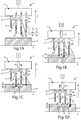
figure 1A shows a multi-bit drilling machine in a first step of the drilling method according to the present invention; -
Figure 1B shows the multi-bit drilling machine in a second step of the drilling method according to the present invention; -
figure 1C shows the multi-bit drilling machine in a second step of the drilling method according to the present invention; -
figure 1D shows the multi-bit drilling machine in a second step of the drilling method according to the present invention; -
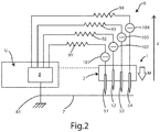
figure 2 shows a system for measuring the alignment differences of the drill bits for the implementation of a method according to the present invention; -
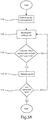
figure 3A shows a flow chart of the drilling method according to the present invention; -
figure 3B shows a first explanatory flowchart of the first processing block of the method offigure 3A ; and -
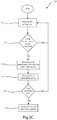
figure 3C shows a second explanatory flowchart of the first processing block of the method offigure 3A . - Referring to
figures 1A-1D , a drilling machine is observed, indicated as a whole with thenumerical reference 1, for the simultaneous production of a plurality of holes F on a panel P, wherein said holes F all have a predetermined depth D. - In particular, said
drilling machine 1 ormachine 1 comprises a control unit U, adrilling unit 2, having a plurality ofspindles drilling bits worktop 3. - Said control unit U is for example a computer.
- Said
drilling unit 2 is operatively connected to said control unit U. - Furthermore, said
drilling unit 2 is movable on a vertical axis Z, in the present example perpendicular with respect to theunderlying worktop 3, on which the panel P to be worked is arranged. - In alternative embodiments, said Z axis may be any direction of movement Z, and may also be non-perpendicular with respect to the
worktop 3, on which the panel P to be worked is arranged. - The
drilling unit 2 can assume different height positions with respect to saidworktop 3, so as to work panels P of different thickness and adjust the depth D of the holes F to be made on said panels P. - Specifically, the adjustment of the working height of said
drilling unit 2 can take place with suitable pneumatic or hydraulic programmable means, controlled by said control unit U, to allow the exchange of thedrilling bits - Said plurality of spindles comprises in the present embodiment four
spindles drilling machine 1. - Each
spindle spindle - The passage from said extracted position to said retracted position of said supports 41', 42', 43', and 44', and/or of said
spindles - Said supports 41', 42', 43', and 44' and/or said
spindles - Finally, the
drilling machine 1 comprises fourbits respective spindle - In the following with "spindle in extracted position" will be indicated each spindle installed on a support in an extracted position, or each spindle, not associated with any stem, in an extracted position, and with the term "spindle in a retracted position" each spindle installed on a support in a retracted position or each spindle, not associated with any stem, in the retracted position.
- Similarly, each bit coupled with a respective spindle in the extracted position will be indicated with the term "extracted bit" or "bit in the extracted position", and with the term "retracted bit" or "bit in the retracted position" each bit coupled with a respective spindle in retracted position.
- The operation of the
multi-point drilling machine 1 described above takes place as follows - choosing the initial position of said
spindles spindles figure 1A , the supports 42', 43', 44' are in the extracted position, while the support 41' alone is in the retracted position. Therefore, thedrilling bits respective mandrels - determining the position with respect to the Z axis of the end of one of the
bits bit 53 is taken as reference, which, in the configuration at issue, has the bit closest to the panel P to be drilled with respect to the other extractedbits - measuring the offsets of each further extracted
bit reference bit 53. More precisely, the distances or level differences are determined, always with respect to the Z axis, of saidreference bit 53 with respect to said other two bits, indicated in the figures with Δ32 and Δ34; - sort said offsets Δ32 and Δ34 measured, from the smallest to the largest;
- lowering said
drilling unit 2, so that thereference bit 53 creates a respective hole F having a predefined depth D; and - subsequently, as soon as said
reference bit 53 reaches the drilling depth D, pass themandrel 43 associated with saidbit 53 from said extracted position to said retracted position; - said
base unit 2 is further lowered by the smaller measured offset value, i.e., in the case at issue, by Δ32, so that the extractedbit 52 realizes the respective hole F of depth D on said panel P; - subsequently the
mandrel 42 associated with said at least one extractedbit 52 passes from said extracted position to said retracted position; and - iterate the last two steps, causing each
drilling unit 2 to lower each time by the difference between two consecutive ordered offsets, so that each remaining extractedbit 54 creates a hole F of depth D on said panel P. In the case at issue, therefore, saiddrilling unit 2 is lowered by the value of the distance equal to the difference Δ34-Δ32, so that saidbit 54 makes a respective depth hole D. - In this way, the three holes made by the
bits - If two or more extracted bits are present, the ends of which are aligned with respect to said Z-axis, each of said two or more extracted bits will, by means of the described method, simultaneously produce a respective hole F of depth D on the panel P. In this case, each of said two or more bits will pass into the retracted position after the realization of said hole F of depth D. This passage can take place simultaneously (when two or more bits are exactly aligned) or, more generally, in sequence.
- If the panels P machining requires that said extracted
bits 52 53, and 54 make respective holes F having respective depths D2, D3, and D4 different from each other, it is sufficient to add to the values of each measured offset Δ32 and Δ34 a respective value δ2 and δ4 equal to the difference between the depth D2 and D3 associated with the respective hole F of each further extractedbit reference bit 53. These new offset values will be the offset values to be ordered from the smallest to the largest during the operation of saiddrilling machine 1. - Finally, both in the case just described and in that in which the reference bit is not the bit closest to the panel P to be drilled, an offset value of 0 will be assigned to said reference point.
- Subsequently, all the offset values to be used during the machine operation will be sorted from the minimum value to the maximum value, and the first bit to reach the (respective) predetermined depth D2, D3, D4, and which will pass first in the retracted position, will be the bit associated with said minimum offset value, taking into account the sign.
- In any case, all the
bits figures 1A and 1B , are initially in the extracted position, must have a length greater than the depth D of the holes F to be made on the panels P, and the height of the panel with respect to said Z axis has to be determined or determinable. - Referring to
figure 2 , saidmachine 1 can comprise ameasuring system 6 for measuring said offsets among said extractedbits - In particular, said measuring
system 6 comprises aconductive plate 7, a detectingmodule 8, a plurality ofimpedances current generators - Said
conductive plate 7 is in fact made of electrically conductive material. - Furthermore, said conducting
plate 7 rests on saidworktop 3, and can have a negligible thickness with respect to the height of said panel P with reference to said axis Z. - The detecting
module 8 is electrically connected to saidconductive plate 7 on acommon node 81. - In particular, the detecting
module 8 can be a functional part of said control unit U of saiddrilling machine 1, or it can be controlled by it. - Furthermore, each one of said
impedances module 8, and in series to a respectivecurrent generator - Each of said
current generators respective bit - In alternative embodiments, said
impedances bits - Said connection between each
current generator respective bit - The operation of said measuring
system 6, when connected to saiddrilling machine 1, takes place in the following way:
Starting from a reference position with respect to the Z axis, saiddrilling unit 2 is first lowered according to the arrow A until the extractedbit 51, which infigure 2 is the closest to theconductive plate 7, comes into electrical contact with said conductingplate 7, closing the electrical circuit comprising said conductingplate 7 itself, said detectingmodule 8, saidbit 51, therespective impedance 91 connected to saidbit 51, and thecurrent generator 101 thereof. - In this way, the detecting
module 8 detects the passage of current in the aforementioned circuit relating to thebit 51, and detects and stores the position of thedrilling unit 2, with respect to said Z-axis with respect to saidbit 51. - Said
bit 51 then passes from said extracted position to said retracted position. - The same procedure for measuring the position of the
drilling unit 2 is repeated for theother bits figure 2 ). - Subsequently, said
drilling unit 2 is raised, returning to the initial position. - Finally, each support 41', 43', 44', whose position has been detected, is passed from said retracted position to said extracted position, after the
drilling unit 2 has been raised. - As regards the memorized position of the bits, said measuring
system 6 can memorize the position of saiddrilling unit 2, with respect to said Z axis, whenever apoint plate 7 by closing the circuit, for example using as reference the initial position of saiddrilling unit 2, or the position of saiddrilling unit 2 when thefirst bit 51 touches said conductingplate 7. - Alternatively, said measuring system can comprise a load cell, alternative to said
conductive plate 7, and a detecting module. - Said load cell (not shown in the figures), in fact, will generate an electrical signal towards said detection module when mechanically stressed, or when touched by said drilling points 51, 52, 53, 54.
- Furthermore, both in the case in which said measuring system comprises said
conductive plate 7, and in the case in which a load cell is present, said conductive plate or said load cell can be integrated directly into saidworktop 3. - Subsequently, said measuring
system 6 will be able to calculate the value of said offsets Δij, starting from said measured values and/or the relative lowering between each bit, whose position has been measured in subsequent surveys, possibly together with information that allow to identify the order in which said bits touched said conductingplate 7 or said load cell. - Alternatively, said measuring
system 6 can store the height of saiddrilling unit 2, with respect to said Z axis, when saidreference bit 51 touches said conductingplate 7 or said load cell during the first detection, while in the following detections it can detect and store directly the relative lowering, with respect to the first or the previous detected bit, of saiddrilling unit 2 with respect to said Z axis, possibly together with the information that allows to identify the order in which said bits have touched saidconductive plate 7 or said load cell. - An example of a method for tracing the order in which said
bits plate 7 or said load cell consists in saving the heights of saiddrilling unit 2 detected with respect to said Z axis in a single ordered vector. - In fact, each element of said ordered vector can be associated with a particular support 41', 43', 44' in an extracted position, and it is sufficient to order said heights measured from the smallest to the largest, to trace the order in which said
bits - Finally, as an alternative to the above-mentioned automatic measurement method, it is possible to detect the positions of said points with respect to said Z-axis, by means of a semi-manual or completely manual method.
- For example, an operator can enter, as input values to said control unit U, the distance of each extracted tip from the panel P with respect to said Z-axis.
- A program internal to said control unit U will therefore be able to choose a reference bit and calculate the relative offsets, or it will be the operator himself to supply this information manually.
- Referring to
figures 3A-3C , an explanatory flowcharts of a drilling method can be observed, which can be implemented as a computer program, performed by said control unit U. - With particular reference to
figure 3A , the implementation of the drilling method comprises the following main steps, briefly described below. - In a
first step 110, the position of saiddrilling bits - In
step 120, thedrilling unit 2 is moved along the direction of movement Z. - In a
third control step 130, it is checked whether at least one extracteddrill bit control step 130 is not verified, it returns to thesecond processing step 120. Else, if saidthird control step 130 is verified,step 140 is continued, in which the extractedtip - Subsequently, in a
fifth control step 150, subsequent to saidfourth step 140, it is checked whether there is at least onebit fifth control step 150 is not verified, the drilling procedure is terminated, else, if saidfifth control step 150 is verified, it returns to saidsecond processing step 120. - Referring to
figures 3B and3C , two respective flowcharts are observed to specify the possible internal actions of saidfirst processing step 110. - In particular, with reference to
figure 3B , saidfirst processing step 110 can comprise the following sub-steps: - a
first sub-step 111, in which adrilling bit - a
second sub-step 112, in which the alignment difference Δij, Δ32, Δ34 is measured, with respect to said direction of movement Z, between said reference bit and thedrilling bits - Optionally, said
first processing step 110 can also have as input the position of the panel P to be drilled. - With reference to
figure 3C , when saiddrilling machine 1 comprises said measuringsystem 6, saidfirst processing step 110 can comprise the following sub-steps: - a sub-step 111', in which said
drilling unit 2 is moved along said direction of movement Z; and - a subsequent control sub-step 112', to check whether said detecting
module 8 detects the passage of a current generated by at least one of saidcurrent generators respective impedance drilling unit 2; - a sub-step 114', subsequent to said fifth sub-step 113', for passing the
respective tip - Furthermore, there is a control sub-step 115', to verify that all the
drill bits tips - Finally, it should be noted that said drilling method can be implemented in such a way as to measure the relative offset between all the drill bits, both if there are drill bits in the extracted position, and in the retracted position, and in case of all the tips are in the retracted position. In such cases, the first step in which it is detected which bits are in the extracted position may not be carried out and all subsequent steps may refer to the bits in the extracted or retracted position.
- The present invention has been described for illustrative but not limitative purposes, according to its preferred embodiments, but it is to be understood that modifications and/or changes can be introduced by those skilled in the art without departing from the relevant scope as defined in the enclosed claims.
- The method according to the present invention allows creating multiple precision holes starting from a plurality of
misaligned bits drilling machine 1, such that the precision of the holes F does not depend on the initial misalignment of saidbits - A further advantage of the present invention is represented by the fact that the measurement of such misalignments of said
bits - In addition to the greater precision of the multiple holes F created through the method according to the present invention, a further advantage is represented by the higher execution speed of both the automatic misalignment measurement method and the drilling method.
- Furthermore, the drilling method according to the present invention is advantageously independent of the height of the panel to be drilled, measured along the direction of movement Z of said
drilling unit 2. - Furthermore, the systems and methods implemented for adjusting the misalignment of the
bits - Additionally, the automatic bit misalignment measurement method and/or the drilling method described employ an extremely limited number of computational resources when implemented within computers.
- Another advantage of the present invention is given by the fact that the drilling machines already on the market can be adapted in such a way as to implement this drilling method.
- Furthermore, the automatic measuring system for the misalignment of the bits can be connected to the machines of the prior art.
- A further advantage of the present invention is that the panels can be drilled with holes having programmable misalignments.
- Finally, a further advantage of the present invention is the fact that these programmable misalignments can be varied during the machining of the panels, further minimizing the machine downtimes.
Claims (15)
- Method for drilling panels (P) by two or more drilling bits (51, 52, 53, 54) to drill at least one panel (P), wherein said drilling bits (51, 52, 53, 54) are installed on a drilling unit (2), movable along at least one movement direction (Z), and wherein each of said drilling bits (51, 52, 53, 54) is configured to assume an extracted position, in which is capable of drilling said at least one panel (P), and a retracted position, in which is not capable of drilling said at least one panel (P),
wherein said method comprising the following steps:A. arranging two or more drilling bits (51, 52, 53, 54) in said extracted position;B. detecting (110) the relative position (Δij, Δ32, Δ34) among said drilling bits (51, 52, 53, 54) in said extracted position or in said retracted position;C. handling (120, 130) said drilling unit (2) along said at least one movement direction (Z), so that said drilling bits (51, 52, 53, 54) in said extracted position carry out a respective hole (F) having a respective drilling depth (D, D1, D2, D3, D4); andD. switching (140) each of said drilling bits (51, 52, 53, 54) in the extracted position from said extracted position to said retracted position, any time each drilling bit (51, 52, 53, 54) reaches the respective drilling depth (D, D1, D2, D3, D4). - Method according to claim 1, characterized in that the relative position (Δij, Δ32, Δ34) among said drilling bits (51, 52, 53, 54) in said extracted or retracted position is equal to the alignment difference along said movement direction (Z), among each tip of said bits (51, 52, 53, 54).
- Method according to any one of the preceding claims, characterized in that the relative position (Δij, Δ32, Δ34) of each drilling bit (51, 52, 53, 54) in said extracted or retracted position is detected with respect to the drill tip of a first of said extracted or retracted drilling bits (51, 52, 53, 54), preferably the extracted (53) or retracted bit whose tip for drilling is closer to the surface of said panel (P).
- Method according to any one of the preceding claims,
wherein said panel (P) is arranged on a worktop (3), and
wherein said method is characterized in that said at least one movement direction (Z) is perpendicular to said worktop (3). - Method according to claim 4, characterized in that said detecting (110) step B further comprises the following sub-steps:B1. detecting the distance of each extracted bit (51, 52, 53, 54) from said worktop (3);B2. subtracting from each value obtained in the step B1 the thickness of said panel (P) along said movement direction (Z); andB3. adding the predetermined drilling depth value (D, D1, D2, D3, D4) to each value obtained in step B2, so as to obtain movement values of said drilling unit (2) during said step B.
- Method according to any one of the preceding claims, characterized in that said drilling depth (D, D1, D2, D3, D4) of said bits (51, 52, 53, 54) are equal to each other.
- Drilling machine (1) for drilling panels (P), comprising
a drilling unit (2), movable along one direction of movement (Z), and comprising
a plurality of spindles (41, 42, 43, 44), each capable of selectively switching from an extracted position to a retracted position and vice versa, and
a plurality of drilling bits (51, 52, 53, 54) each fixed on one of the respective of said spindles (41, 42, 43, 44), and
a control unit (U), operationally connected to said drilling unit (2), to handle said drilling unit along said movement direction (Z) and to switch said spindles (41, 42, 43, 44) from said extracted position to said retracted position and vice versa,
said drilling machine (1) being characterized in that said control unit (U) is configured to carry out the method according to any one of the preceding claims. - Drilling machine (1) according to the preceding claim, characterized in that it comprises a worktop (3) for supporting said panels (P) to be drilled.
- Drilling machine (1) according to any of the claims 7 - 8, characterized
in that it comprises a measurement system (6), which comprisesa conductive plate (7), to be arranged in a reference position, at least one current generator (101, 102, 103, 104), electrically connected to a respective drilling bit (51, 52, 53, 54), said at least one current generator being capable of generating a reference current on command,a plurality of resistors (91, 92, 93, 94), each series connected to said at least one generator (101, 102, 103, 104),a detecting module (8), electrically connected to said conductive plate (7) through a common knot (81) and to each of said resistors (91, 92, 93, 94),wherein said drilling unit is moved along said movement direction (Z) toward said conductive plate (7), so that, when each drilling bit (51, 52, 53, 54) touches said conductive plate (7), said at least one current generator (101, 102, 103, 104) generates a current and said detecting module (8) detects the passage of said generated current passing through the respective resistor (91, 92, 93, 94), so as to detect the relative position of said drilling unit (2), and said control unit (U) passes said drilling bit (51, 52, 53, 54) from said extracted position to said retracted position. - Drilling machine (1) according to any one of claims 7 - 8 characterized
in that it comprises a measure system (6), comprisinga load cell, to be arranged in a reference position,a detecting module, electrically connected to said load cell,wherein said drilling unit is moved along said movement direction (Z) to said load cell, so that, when said load cell detects a stress caused by each drilling bit (51, 52, 53, 54), said load cell generates an electrical signal to said detecting module so as to detect the position of said drilling unit (2), and said control unit (U) switches said drilling bit (51, 52, 53, 54) from said extracted position to said retracted position. - Drilling machine (1) according to any one of claims 9 - 10, characterized in that said detecting module (8) is incorporated in said control unit (U).
- Drilling machine (1) according to any one of claims 9 - 11, characterized in that said conductive plate (7) or said load cell is arranged on said worktop (3).
- Drilling machine (1) according to any one of claims 9 - 11, when dependent on claim 8, characterized in that said conductive plate (7) or said load cell is incorporated in said worktop (3).
- Computer program comprising instructions that, when the program is executed by a computer, cause the execution, by the computer, of the steps A-D of the method according to any of the claims 1-6.
- Computer readable storage medium comprising instructions that, when executed by a computer, cause the execution, by the computer, of the steps A-D of the method according to any of the claims 1-6.
Applications Claiming Priority (1)
| Application Number | Priority Date | Filing Date | Title |
|---|---|---|---|
| IT201900006745 | 2019-05-13 |
Publications (2)
| Publication Number | Publication Date |
|---|---|
| EP3738702A1 true EP3738702A1 (en) | 2020-11-18 |
| EP3738702B1 EP3738702B1 (en) | 2024-05-22 |
Family
ID=67660713
Family Applications (1)
| Application Number | Title | Priority Date | Filing Date |
|---|---|---|---|
| EP20170809.6A Active EP3738702B1 (en) | 2019-05-13 | 2020-04-22 | Drilling method for multi bit drilling machine and corresponding drilling machine using such method |
Country Status (1)
| Country | Link |
|---|---|
| EP (1) | EP3738702B1 (en) |
Cited By (4)
| Publication number | Priority date | Publication date | Assignee | Title |
|---|---|---|---|---|
| CN112512222A (en) * | 2020-11-30 | 2021-03-16 | 维嘉数控科技(苏州)有限公司 | Multi-axis drilling method and device for multi-layer PCB |
| CN114472953A (en) * | 2022-03-25 | 2022-05-13 | 临沂鲁南分析测试研究所 | Plate section punching processing equipment |
| CN115740537A (en) * | 2022-11-07 | 2023-03-07 | 济南法特数控机械有限责任公司 | Method for determining distance between main shafts and row spacing of multi-main-shaft multi-row numerical control sieve plate drilling equipment |
| CN118808716A (en) * | 2024-09-20 | 2024-10-22 | 新乡天鑫新能源机械有限公司 | A planetary gear multi-axis combined drilling device |
Citations (5)
| Publication number | Priority date | Publication date | Assignee | Title |
|---|---|---|---|---|
| US3481247A (en) * | 1966-11-23 | 1969-12-02 | Hayes Eng Leeds Ltd | Tool height setting apparatus |
| JPH06126514A (en) * | 1991-10-28 | 1994-05-10 | Nippei Toyama Corp | Machine Tools |
| JP2866709B2 (en) * | 1990-05-31 | 1999-03-08 | 立山アルミニウム工業株式会社 | Multiple processing method and device |
| JP2012166292A (en) * | 2011-02-14 | 2012-09-06 | Mitsubishi Heavy Ind Ltd | Method, member and device for aligning axial position of each cutting tool in multi-spindle drilling machine |
| EP2783777A1 (en) * | 2013-03-27 | 2014-10-01 | Le Creneau Industriel | Drilling device and drilling method using such a drilling device |
-
2020
- 2020-04-22 EP EP20170809.6A patent/EP3738702B1/en active Active
Patent Citations (5)
| Publication number | Priority date | Publication date | Assignee | Title |
|---|---|---|---|---|
| US3481247A (en) * | 1966-11-23 | 1969-12-02 | Hayes Eng Leeds Ltd | Tool height setting apparatus |
| JP2866709B2 (en) * | 1990-05-31 | 1999-03-08 | 立山アルミニウム工業株式会社 | Multiple processing method and device |
| JPH06126514A (en) * | 1991-10-28 | 1994-05-10 | Nippei Toyama Corp | Machine Tools |
| JP2012166292A (en) * | 2011-02-14 | 2012-09-06 | Mitsubishi Heavy Ind Ltd | Method, member and device for aligning axial position of each cutting tool in multi-spindle drilling machine |
| EP2783777A1 (en) * | 2013-03-27 | 2014-10-01 | Le Creneau Industriel | Drilling device and drilling method using such a drilling device |
Cited By (4)
| Publication number | Priority date | Publication date | Assignee | Title |
|---|---|---|---|---|
| CN112512222A (en) * | 2020-11-30 | 2021-03-16 | 维嘉数控科技(苏州)有限公司 | Multi-axis drilling method and device for multi-layer PCB |
| CN114472953A (en) * | 2022-03-25 | 2022-05-13 | 临沂鲁南分析测试研究所 | Plate section punching processing equipment |
| CN115740537A (en) * | 2022-11-07 | 2023-03-07 | 济南法特数控机械有限责任公司 | Method for determining distance between main shafts and row spacing of multi-main-shaft multi-row numerical control sieve plate drilling equipment |
| CN118808716A (en) * | 2024-09-20 | 2024-10-22 | 新乡天鑫新能源机械有限公司 | A planetary gear multi-axis combined drilling device |
Also Published As
| Publication number | Publication date |
|---|---|
| EP3738702B1 (en) | 2024-05-22 |
Similar Documents
| Publication | Publication Date | Title |
|---|---|---|
| EP3738702B1 (en) | Drilling method for multi bit drilling machine and corresponding drilling machine using such method | |
| US4596067A (en) | Drilling machine for boards, particularly of printed circuits | |
| CA2828888C (en) | Drilling machine having hole measurement capability | |
| US20150056030A1 (en) | Automated inspection system | |
| CN109531262B (en) | Contact feedback type automatic measurement method and system for numerical control machine tool and storage medium | |
| CN204790502U (en) | An Online Measurement System for CNC Machine Tool | |
| CN115592414A (en) | A multi-robot collaborative processing device and method for slender cylindrical parts | |
| CN201253780Y (en) | Circuit board drilling depth testing block | |
| CN105364102A (en) | Drilling method and drilling machine thereof | |
| KR20220148017A (en) | Machine tool abnormality diagnosis data collecting system based on machine learning and method thereof | |
| CN106938360A (en) | A kind of manual-auto integrated punch | |
| CN103801726B (en) | A kind of hollow tubular work pieces process special drill press | |
| US8346383B2 (en) | Method for determining the machining quality of components, particularly for metal cutting by NC machines | |
| CN210848414U (en) | Automatic position-finding drilling machine | |
| CN117564804B (en) | An automatic feed drilling test device | |
| CN207873172U (en) | A kind of drilling holes on circuit board high-precision positioner | |
| CN114322894B (en) | Universal hole diameter flexible measurement method | |
| CN203509114U (en) | Drilling equipment capable of automatically adjusting drilling angles | |
| CN203765037U (en) | Drilling power head automatically controlling feeding states | |
| CN204673698U (en) | Drilling machine needle exchange mechanism | |
| CN222609471U (en) | Drill bit limiter installation tool | |
| CN117459158B (en) | Comprehensive logging instrument signal channel testing system and testing method | |
| JPH04310353A (en) | Blind hole machining method | |
| CN109623875A (en) | A kind of Automatic adjustment method that cutter axial cutters are mended | |
| CN213748379U (en) | Auxiliary positioning device for measuring roughness of surface hole of gearbox valve body |
Legal Events
| Date | Code | Title | Description |
|---|---|---|---|
| PUAI | Public reference made under article 153(3) epc to a published international application that has entered the european phase |
Free format text: ORIGINAL CODE: 0009012 |
|
| STAA | Information on the status of an ep patent application or granted ep patent |
Free format text: STATUS: THE APPLICATION HAS BEEN PUBLISHED |
|
| AK | Designated contracting states |
Kind code of ref document: A1 Designated state(s): AL AT BE BG CH CY CZ DE DK EE ES FI FR GB GR HR HU IE IS IT LI LT LU LV MC MK MT NL NO PL PT RO RS SE SI SK SM TR |
|
| AX | Request for extension of the european patent |
Extension state: BA ME |
|
| STAA | Information on the status of an ep patent application or granted ep patent |
Free format text: STATUS: REQUEST FOR EXAMINATION WAS MADE |
|
| 17P | Request for examination filed |
Effective date: 20210319 |
|
| RBV | Designated contracting states (corrected) |
Designated state(s): AL AT BE BG CH CY CZ DE DK EE ES FI FR GB GR HR HU IE IS IT LI LT LU LV MC MK MT NL NO PL PT RO RS SE SI SK SM TR |
|
| P01 | Opt-out of the competence of the unified patent court (upc) registered |
Effective date: 20230518 |
|
| GRAP | Despatch of communication of intention to grant a patent |
Free format text: ORIGINAL CODE: EPIDOSNIGR1 |
|
| STAA | Information on the status of an ep patent application or granted ep patent |
Free format text: STATUS: GRANT OF PATENT IS INTENDED |
|
| INTG | Intention to grant announced |
Effective date: 20240111 |
|
| GRAS | Grant fee paid |
Free format text: ORIGINAL CODE: EPIDOSNIGR3 |
|
| GRAA | (expected) grant |
Free format text: ORIGINAL CODE: 0009210 |
|
| STAA | Information on the status of an ep patent application or granted ep patent |
Free format text: STATUS: THE PATENT HAS BEEN GRANTED |
|
| AK | Designated contracting states |
Kind code of ref document: B1 Designated state(s): AL AT BE BG CH CY CZ DE DK EE ES FI FR GB GR HR HU IE IS IT LI LT LU LV MC MK MT NL NO PL PT RO RS SE SI SK SM TR |
|
| REG | Reference to a national code |
Ref country code: GB Ref legal event code: FG4D |
|
| REG | Reference to a national code |
Ref country code: CH Ref legal event code: EP |
|
| REG | Reference to a national code |
Ref country code: DE Ref legal event code: R096 Ref document number: 602020031180 Country of ref document: DE |
|
| REG | Reference to a national code |
Ref country code: IE Ref legal event code: FG4D |
|
| REG | Reference to a national code |
Ref country code: LT Ref legal event code: MG9D |
|
| REG | Reference to a national code |
Ref country code: NL Ref legal event code: MP Effective date: 20240522 |
|
| PG25 | Lapsed in a contracting state [announced via postgrant information from national office to epo] |
Ref country code: IS Free format text: LAPSE BECAUSE OF FAILURE TO SUBMIT A TRANSLATION OF THE DESCRIPTION OR TO PAY THE FEE WITHIN THE PRESCRIBED TIME-LIMIT Effective date: 20240922 |
|
| PG25 | Lapsed in a contracting state [announced via postgrant information from national office to epo] |
Ref country code: BG Free format text: LAPSE BECAUSE OF FAILURE TO SUBMIT A TRANSLATION OF THE DESCRIPTION OR TO PAY THE FEE WITHIN THE PRESCRIBED TIME-LIMIT Effective date: 20240522 |
|
| PG25 | Lapsed in a contracting state [announced via postgrant information from national office to epo] |
Ref country code: FI Free format text: LAPSE BECAUSE OF FAILURE TO SUBMIT A TRANSLATION OF THE DESCRIPTION OR TO PAY THE FEE WITHIN THE PRESCRIBED TIME-LIMIT Effective date: 20240522 Ref country code: HR Free format text: LAPSE BECAUSE OF FAILURE TO SUBMIT A TRANSLATION OF THE DESCRIPTION OR TO PAY THE FEE WITHIN THE PRESCRIBED TIME-LIMIT Effective date: 20240522 |
|
| PG25 | Lapsed in a contracting state [announced via postgrant information from national office to epo] |
Ref country code: GR Free format text: LAPSE BECAUSE OF FAILURE TO SUBMIT A TRANSLATION OF THE DESCRIPTION OR TO PAY THE FEE WITHIN THE PRESCRIBED TIME-LIMIT Effective date: 20240823 |
|
| PG25 | Lapsed in a contracting state [announced via postgrant information from national office to epo] |
Ref country code: PT Free format text: LAPSE BECAUSE OF FAILURE TO SUBMIT A TRANSLATION OF THE DESCRIPTION OR TO PAY THE FEE WITHIN THE PRESCRIBED TIME-LIMIT Effective date: 20240923 |
|
| PG25 | Lapsed in a contracting state [announced via postgrant information from national office to epo] |
Ref country code: NL Free format text: LAPSE BECAUSE OF FAILURE TO SUBMIT A TRANSLATION OF THE DESCRIPTION OR TO PAY THE FEE WITHIN THE PRESCRIBED TIME-LIMIT Effective date: 20240522 |
|
| PG25 | Lapsed in a contracting state [announced via postgrant information from national office to epo] |
Ref country code: ES Free format text: LAPSE BECAUSE OF FAILURE TO SUBMIT A TRANSLATION OF THE DESCRIPTION OR TO PAY THE FEE WITHIN THE PRESCRIBED TIME-LIMIT Effective date: 20240522 |
|
| PG25 | Lapsed in a contracting state [announced via postgrant information from national office to epo] |
Ref country code: PL Free format text: LAPSE BECAUSE OF FAILURE TO SUBMIT A TRANSLATION OF THE DESCRIPTION OR TO PAY THE FEE WITHIN THE PRESCRIBED TIME-LIMIT Effective date: 20240522 |
|
| PG25 | Lapsed in a contracting state [announced via postgrant information from national office to epo] |
Ref country code: LV Free format text: LAPSE BECAUSE OF FAILURE TO SUBMIT A TRANSLATION OF THE DESCRIPTION OR TO PAY THE FEE WITHIN THE PRESCRIBED TIME-LIMIT Effective date: 20240522 |
|
| PG25 | Lapsed in a contracting state [announced via postgrant information from national office to epo] |
Ref country code: PT Free format text: LAPSE BECAUSE OF FAILURE TO SUBMIT A TRANSLATION OF THE DESCRIPTION OR TO PAY THE FEE WITHIN THE PRESCRIBED TIME-LIMIT Effective date: 20240923 Ref country code: PL Free format text: LAPSE BECAUSE OF FAILURE TO SUBMIT A TRANSLATION OF THE DESCRIPTION OR TO PAY THE FEE WITHIN THE PRESCRIBED TIME-LIMIT Effective date: 20240522 Ref country code: NO Free format text: LAPSE BECAUSE OF FAILURE TO SUBMIT A TRANSLATION OF THE DESCRIPTION OR TO PAY THE FEE WITHIN THE PRESCRIBED TIME-LIMIT Effective date: 20240822 Ref country code: NL Free format text: LAPSE BECAUSE OF FAILURE TO SUBMIT A TRANSLATION OF THE DESCRIPTION OR TO PAY THE FEE WITHIN THE PRESCRIBED TIME-LIMIT Effective date: 20240522 Ref country code: LV Free format text: LAPSE BECAUSE OF FAILURE TO SUBMIT A TRANSLATION OF THE DESCRIPTION OR TO PAY THE FEE WITHIN THE PRESCRIBED TIME-LIMIT Effective date: 20240522 Ref country code: IS Free format text: LAPSE BECAUSE OF FAILURE TO SUBMIT A TRANSLATION OF THE DESCRIPTION OR TO PAY THE FEE WITHIN THE PRESCRIBED TIME-LIMIT Effective date: 20240922 Ref country code: HR Free format text: LAPSE BECAUSE OF FAILURE TO SUBMIT A TRANSLATION OF THE DESCRIPTION OR TO PAY THE FEE WITHIN THE PRESCRIBED TIME-LIMIT Effective date: 20240522 Ref country code: GR Free format text: LAPSE BECAUSE OF FAILURE TO SUBMIT A TRANSLATION OF THE DESCRIPTION OR TO PAY THE FEE WITHIN THE PRESCRIBED TIME-LIMIT Effective date: 20240823 Ref country code: FI Free format text: LAPSE BECAUSE OF FAILURE TO SUBMIT A TRANSLATION OF THE DESCRIPTION OR TO PAY THE FEE WITHIN THE PRESCRIBED TIME-LIMIT Effective date: 20240522 Ref country code: ES Free format text: LAPSE BECAUSE OF FAILURE TO SUBMIT A TRANSLATION OF THE DESCRIPTION OR TO PAY THE FEE WITHIN THE PRESCRIBED TIME-LIMIT Effective date: 20240522 Ref country code: BG Free format text: LAPSE BECAUSE OF FAILURE TO SUBMIT A TRANSLATION OF THE DESCRIPTION OR TO PAY THE FEE WITHIN THE PRESCRIBED TIME-LIMIT Effective date: 20240522 Ref country code: RS Free format text: LAPSE BECAUSE OF FAILURE TO SUBMIT A TRANSLATION OF THE DESCRIPTION OR TO PAY THE FEE WITHIN THE PRESCRIBED TIME-LIMIT Effective date: 20240822 |
|
| PG25 | Lapsed in a contracting state [announced via postgrant information from national office to epo] |
Ref country code: DK Free format text: LAPSE BECAUSE OF FAILURE TO SUBMIT A TRANSLATION OF THE DESCRIPTION OR TO PAY THE FEE WITHIN THE PRESCRIBED TIME-LIMIT Effective date: 20240522 |
|
| PG25 | Lapsed in a contracting state [announced via postgrant information from national office to epo] |
Ref country code: EE Free format text: LAPSE BECAUSE OF FAILURE TO SUBMIT A TRANSLATION OF THE DESCRIPTION OR TO PAY THE FEE WITHIN THE PRESCRIBED TIME-LIMIT Effective date: 20240522 |
|
| PG25 | Lapsed in a contracting state [announced via postgrant information from national office to epo] |
Ref country code: CZ Free format text: LAPSE BECAUSE OF FAILURE TO SUBMIT A TRANSLATION OF THE DESCRIPTION OR TO PAY THE FEE WITHIN THE PRESCRIBED TIME-LIMIT Effective date: 20240522 |
|
| PG25 | Lapsed in a contracting state [announced via postgrant information from national office to epo] |
Ref country code: RO Free format text: LAPSE BECAUSE OF FAILURE TO SUBMIT A TRANSLATION OF THE DESCRIPTION OR TO PAY THE FEE WITHIN THE PRESCRIBED TIME-LIMIT Effective date: 20240522 Ref country code: SK Free format text: LAPSE BECAUSE OF FAILURE TO SUBMIT A TRANSLATION OF THE DESCRIPTION OR TO PAY THE FEE WITHIN THE PRESCRIBED TIME-LIMIT Effective date: 20240522 |
|
| PG25 | Lapsed in a contracting state [announced via postgrant information from national office to epo] |
Ref country code: SM Free format text: LAPSE BECAUSE OF FAILURE TO SUBMIT A TRANSLATION OF THE DESCRIPTION OR TO PAY THE FEE WITHIN THE PRESCRIBED TIME-LIMIT Effective date: 20240522 |
|
| PG25 | Lapsed in a contracting state [announced via postgrant information from national office to epo] |
Ref country code: SM Free format text: LAPSE BECAUSE OF FAILURE TO SUBMIT A TRANSLATION OF THE DESCRIPTION OR TO PAY THE FEE WITHIN THE PRESCRIBED TIME-LIMIT Effective date: 20240522 Ref country code: SK Free format text: LAPSE BECAUSE OF FAILURE TO SUBMIT A TRANSLATION OF THE DESCRIPTION OR TO PAY THE FEE WITHIN THE PRESCRIBED TIME-LIMIT Effective date: 20240522 Ref country code: RO Free format text: LAPSE BECAUSE OF FAILURE TO SUBMIT A TRANSLATION OF THE DESCRIPTION OR TO PAY THE FEE WITHIN THE PRESCRIBED TIME-LIMIT Effective date: 20240522 Ref country code: EE Free format text: LAPSE BECAUSE OF FAILURE TO SUBMIT A TRANSLATION OF THE DESCRIPTION OR TO PAY THE FEE WITHIN THE PRESCRIBED TIME-LIMIT Effective date: 20240522 Ref country code: DK Free format text: LAPSE BECAUSE OF FAILURE TO SUBMIT A TRANSLATION OF THE DESCRIPTION OR TO PAY THE FEE WITHIN THE PRESCRIBED TIME-LIMIT Effective date: 20240522 Ref country code: CZ Free format text: LAPSE BECAUSE OF FAILURE TO SUBMIT A TRANSLATION OF THE DESCRIPTION OR TO PAY THE FEE WITHIN THE PRESCRIBED TIME-LIMIT Effective date: 20240522 |
|
| REG | Reference to a national code |
Ref country code: DE Ref legal event code: R097 Ref document number: 602020031180 Country of ref document: DE |
|
| PLBE | No opposition filed within time limit |
Free format text: ORIGINAL CODE: 0009261 |
|
| STAA | Information on the status of an ep patent application or granted ep patent |
Free format text: STATUS: NO OPPOSITION FILED WITHIN TIME LIMIT |
|
| PG25 | Lapsed in a contracting state [announced via postgrant information from national office to epo] |
Ref country code: SI Free format text: LAPSE BECAUSE OF FAILURE TO SUBMIT A TRANSLATION OF THE DESCRIPTION OR TO PAY THE FEE WITHIN THE PRESCRIBED TIME-LIMIT Effective date: 20240522 |
|
| 26N | No opposition filed |
Effective date: 20250225 |
|
| PG25 | Lapsed in a contracting state [announced via postgrant information from national office to epo] |
Ref country code: SE Free format text: LAPSE BECAUSE OF FAILURE TO SUBMIT A TRANSLATION OF THE DESCRIPTION OR TO PAY THE FEE WITHIN THE PRESCRIBED TIME-LIMIT Effective date: 20240522 |
|
| REG | Reference to a national code |
Ref country code: AT Ref legal event code: UEP Ref document number: 1688378 Country of ref document: AT Kind code of ref document: T Effective date: 20240522 |
|
| REG | Reference to a national code |
Ref country code: DE Ref legal event code: R119 Ref document number: 602020031180 Country of ref document: DE |
|
| REG | Reference to a national code |
Ref country code: CH Ref legal event code: H13 Free format text: ST27 STATUS EVENT CODE: U-0-0-H10-H13 (AS PROVIDED BY THE NATIONAL OFFICE) Effective date: 20251125 |
|
| PG25 | Lapsed in a contracting state [announced via postgrant information from national office to epo] |
Ref country code: LU Free format text: LAPSE BECAUSE OF NON-PAYMENT OF DUE FEES Effective date: 20250422 |
|
| PG25 | Lapsed in a contracting state [announced via postgrant information from national office to epo] |
Ref country code: MC Free format text: LAPSE BECAUSE OF FAILURE TO SUBMIT A TRANSLATION OF THE DESCRIPTION OR TO PAY THE FEE WITHIN THE PRESCRIBED TIME-LIMIT Effective date: 20240522 |
|
| GBPC | Gb: european patent ceased through non-payment of renewal fee |
Effective date: 20250422 |
|
| REG | Reference to a national code |
Ref country code: BE Ref legal event code: MM Effective date: 20250430 |
|
| PG25 | Lapsed in a contracting state [announced via postgrant information from national office to epo] |
Ref country code: DE Free format text: LAPSE BECAUSE OF NON-PAYMENT OF DUE FEES Effective date: 20251104 |
|
| PG25 | Lapsed in a contracting state [announced via postgrant information from national office to epo] |
Ref country code: GB Free format text: LAPSE BECAUSE OF NON-PAYMENT OF DUE FEES Effective date: 20250422 |
|
| PG25 | Lapsed in a contracting state [announced via postgrant information from national office to epo] |
Ref country code: FR Free format text: LAPSE BECAUSE OF NON-PAYMENT OF DUE FEES Effective date: 20250430 |
|
| PG25 | Lapsed in a contracting state [announced via postgrant information from national office to epo] |
Ref country code: BE Free format text: LAPSE BECAUSE OF NON-PAYMENT OF DUE FEES Effective date: 20250430 |
|
| PG25 | Lapsed in a contracting state [announced via postgrant information from national office to epo] |
Ref country code: CH Free format text: LAPSE BECAUSE OF NON-PAYMENT OF DUE FEES Effective date: 20250430 |
|
| PG25 | Lapsed in a contracting state [announced via postgrant information from national office to epo] |
Ref country code: IE Free format text: LAPSE BECAUSE OF NON-PAYMENT OF DUE FEES Effective date: 20250422 |
|
| PG25 | Lapsed in a contracting state [announced via postgrant information from national office to epo] |
Ref country code: IT Free format text: LAPSE BECAUSE OF NON-PAYMENT OF DUE FEES Effective date: 20250422 |