EP3738368B1 - Devices and methods for multi-antenna sidelink scheduling - Google Patents
Devices and methods for multi-antenna sidelink scheduling Download PDFInfo
- Publication number
- EP3738368B1 EP3738368B1 EP18705875.5A EP18705875A EP3738368B1 EP 3738368 B1 EP3738368 B1 EP 3738368B1 EP 18705875 A EP18705875 A EP 18705875A EP 3738368 B1 EP3738368 B1 EP 3738368B1
- Authority
- EP
- European Patent Office
- Prior art keywords
- communication device
- sidelink communication
- sidelink
- neighboring
- interference
- Prior art date
- Legal status (The legal status is an assumption and is not a legal conclusion. Google has not performed a legal analysis and makes no representation as to the accuracy of the status listed.)
- Active
Links
Images



Classifications
-
- H—ELECTRICITY
- H04—ELECTRIC COMMUNICATION TECHNIQUE
- H04W—WIRELESS COMMUNICATION NETWORKS
- H04W72/00—Local resource management
- H04W72/50—Allocation or scheduling criteria for wireless resources
- H04W72/54—Allocation or scheduling criteria for wireless resources based on quality criteria
- H04W72/541—Allocation or scheduling criteria for wireless resources based on quality criteria using the level of interference
-
- H—ELECTRICITY
- H04—ELECTRIC COMMUNICATION TECHNIQUE
- H04W—WIRELESS COMMUNICATION NETWORKS
- H04W72/00—Local resource management
- H04W72/50—Allocation or scheduling criteria for wireless resources
- H04W72/54—Allocation or scheduling criteria for wireless resources based on quality criteria
- H04W72/542—Allocation or scheduling criteria for wireless resources based on quality criteria using measured or perceived quality
-
- H—ELECTRICITY
- H04—ELECTRIC COMMUNICATION TECHNIQUE
- H04W—WIRELESS COMMUNICATION NETWORKS
- H04W24/00—Supervisory, monitoring or testing arrangements
- H04W24/10—Scheduling measurement reports ; Arrangements for measurement reports
Definitions
- the present invention relates to the field of wireless communication. More specifically, the present invention relates to devices and methods for multi-antenna sidelink scheduling in a V2X communication network, in particular a sidelink communication device and a network entity for allocating sidelink radio resources as well as corresponding methods.
- V2X (Vehicle-to-Everything) services can be provided directly via a so-called PC5 interface (also known as sidelink or D2D communication) and/or indirectly via an LTE-Uu interface (also known as uplink/downlink), as specified in 3GPP TS 36.300 V14.2.0, "LTE; Evolved Universal Terrestrial Radio Access (E-UTRA) and Evolved Universal Terrestrial Radio Access Network (E-UTRAN); Overall description; Stage 2 ".
- Support of V2X services via the PC5 interface is provided by V2X sidelink communication, which is a communication mode in which User Equipments (UEs) such as vehicles can communicate with each other directly via the PC5 interface. This communication mode is supported when the UE is served by E-UTRAN and when the UE is outside of E-UTRA coverage.
- UEs User Equipments
- a UE supporting V2X sidelink communication can operate in two modes for sidelink radio resource allocation: in a first mode, known as scheduled resource allocation, a UE requests radio resources from a base station, and the base station allocates dedicated radio resources to the UE. In a second mode, known as autonomous resource selection, the UE on its own selects radio resources from (pre)configured resource pools.
- the UEs report their locations to the base station.
- the sidelink scheduler e.g., a base station
- the sidelink scheduler is forced to allocate orthogonal resources (in time and/or frequency) to nearby UEs, in order to prevent mutual interference.
- transmissions from nearby UEs may not need to be orthogonalized by the sidelink scheduler if the UEs have multiple antennas.
- a radio resource can be reused by nearby transmissions if the UEs can make use of multi-antenna transmission techniques to mitigate interference.
- GB2500392 describes a user equipment which transmits information associated with its filtering capabilities to a communication counterpart such as a base station or e Node B.
- the counterpart may issue a request for additional information regarding the filtering capabilities of the UE and may use the information when allocating resource blocks to the UE.
- WO2017/218782 describes high order multiple input, multiple output (MIMO) operations in which a user equipment (UE), configured with at least one normal performance receiver chain and at least one low-performance, low-complexity diversity receiver chain, signals a capabilities indicator identifying existence of the low-performance diversity receivers.
- UE user equipment
- WO2012/162788 describes devices and methods are provided for device-assisted interference management in heterogeneous wireless network environments.
- the present invention is defined in the appended claims. It is an object of the invention to provide improved devices and methods for multi-antenna sidelink communication, allowing for more spectrally efficient scheduling of sidelink transmissions.
- the invention can be implemented in hardware and/or software.
- a disclosure in connection with a described method may also hold true for a corresponding device or system configured to perform the method and vice versa.
- a corresponding device may include a unit to perform the described method step, even if such unit is not explicitly described or illustrated in the figures.
- embodiments of the invention relate to a V2X communication network comprising a sidelink communication device and a network entity, which allow for a significant increase in sidelink radio resource reuse.
- Multi-antenna transmission techniques such as beamforming or MIMO (Multiple-Input Multiple-Output), are powerful tools for interference mitigation and SINR (Signal-to-Interference-plus-Noise Ratio) enhancement.
- MIMO processing e.g., through data precoding and/or postcoding
- SINR gains of above 20 dB can be achieved by using, e.g., up to 16 transmitting and receiving antennas.
- available antennas can be used for interference mitigation, diversity and/or data multiplexing gains.
- the embodiments of the present invention can combine beamforming and/or MIMO schemes with sidelink scheduling decisions taken by a network entity in the form of a sidelink scheduler: given two (or more) sidelink communication devices for data transmission, e.g., User Equipments (UEs), a sidelink scheduler such as a base station can determine whether the same radio resource (i.e., time and/or frequency channel) may be used by both UEs. Instead of reporting the full Channel State Information (CSI) to the base station, which would incur considerable control signaling overhead, the UEs can report information about their ability to use multi-antenna transmission/reception to cancel interference to/from nearby UEs, as will be described in more detail in the following.
- CSI Channel State Information
- Figure 1 shows a schematic diagram illustrating a communication network 100 comprising a sidelink communication device ( i ) 101, in particular a multi-antenna sidelink communication device, according to an embodiment, and a network entity 131, according to an embodiment.
- the sidelink communication device ( i ) 101 is configured to communicate with neighboring sidelink communication devices (not shown in figure 1 ) via a sidelink communication channel, and with the network entity 131 via an uplink/downlink communication channel.
- the sidelink communication device ( i ) 101 could be implemented in the form of a user entity such as a mobile phone or a vehicle or a communication module of a vehicle.
- a user entity such as a mobile phone or a vehicle or a communication module of a vehicle.
- the network entity 131 can be, for instance, a base station.
- the sidelink communication device ( i ) 101 comprises a transceiver 103 comprising a plurality of antennas and configured to communicate with at least one neighboring sidelink communication device ( j ) using one or more sidelink radio resources of a plurality of sidelink radio resources allocated by the network entity 131.
- the sidelink communication device ( i ) 101 comprises a processor 105.
- the processor 105 is configured to determine a measure for the ability of the sidelink communication device ( i ) 101 to suppress interference to and/or from at least one other neighboring sidelink communication device ( k ) using one or more of the plurality of antennas.
- the network entity 131 comprises a transceiver 133 configured to receive information about the measure for the ability of the sidelink communication device ( i ) 101 to suppress interference to and/or from at least one other neighboring sidelink communication device ( k ) using one or more of a plurality of antennas of the sidelink communication device ( i ) 101.
- the network entity 131 further comprises a processor 135 configured to allocate one or more of a plurality of sidelink radio resources to the sidelink communication device ( i ) 101 for communication with the at least one neighboring sidelink communication device ( j ) on the basis of the information about the measure for the ability of the sidelink communication device ( i ) 101 to suppress interference to and/or from the at least one other neighboring sidelink communication device ( k ).
- a processor 135 configured to allocate one or more of a plurality of sidelink radio resources to the sidelink communication device ( i ) 101 for communication with the at least one neighboring sidelink communication device ( j ) on the basis of the information about the measure for the ability of the sidelink communication device ( i ) 101 to suppress interference to and/or from the at least one other neighboring sidelink communication device ( k ).
- the transceiver 133 of the network entity 131 is configured to receive information about an identity, a signal strength and/or a location of the at least one other neighboring sidelink communication device ( k ) from the sidelink communication device ( i ) 101.
- the processor 135 of the network entity 131 is configured to determine one or more sidelink reference signals and/or allocate one or more sidelink radio resources for exchanging the one or more sidelink reference signals on the basis of the identity, the signal strength and/or the location of the at least one other neighboring sidelink communication device ( k ), and the transceiver 133 is further configured to transmit to the sidelink communication device ( i ) 101 information about the one or more sidelink reference signals and/or information about the one or more sidelink radio resources for exchanging the one or more sidelink reference signals with the at least one other neighboring sidelink communication device ( k ).
- the transceiver 103 of the sidelink communication device 101 is configured to receive from the network entity 131 information about the one or more sidelink reference signals and/or information about one or more sidelink radio resources for exchanging the one or more sidelink reference signals with the at least one other neighboring sidelink communication device ( k ). More details about the reference signal assignment will be further discussed in the following embodiments.
- the transceiver 103 of the sidelink communication device 101 is configured to transmit the one or more sidelink reference signals on the basis of the information received from the network entity 131 to the at least one other neighboring sidelink communication device ( k ).
- the transceiver 103 is also configured to receive the one or more sidelink reference signals from the at least one other neighboring sidelink communication device ( k ).
- the processor 105 of the sidelink communication device ( i ) 101 determines one or more physical properties of the sidelink communication channel between at least one of the plurality of antennas of the sidelink communication device ( i ) 101 and at least one of a plurality of antennas of the at least one other neighboring sidelink communication device ( k ).
- the processor 105 is configured to determine a measure for the ability of the sidelink communication device ( i ) 101 to suppress interference to and/or from the at least one other neighboring sidelink communication device ( k ) on the basis of the one or more physical properties of the sidelink communication channel, in particular by means of signal processing of one or more signals from the plurality of antennas of the sidelink communication device ( i ) 101.
- the transceiver 103 of the sidelink communication device ( i ) 101 can transmit to the network entity 131 information about the measure for the ability of the sidelink communication device ( i ) 101 to suppress interference, in particular for allocation of the one or more sidelink radio resources by the network entity 131.
- the network entity 131 can allocate one or more of the plurality of sidelink radio resources to the sidelink communication device ( i ) 101 for communication with the at least one neighboring sidelink communication device ( j ) on the basis of the information about the measure for the ability of the sidelink communication device ( i ) 101 to suppress interference to and/or from the at least one other neighboring sidelink communication device ( k ).
- the sidelink communication device ( i ) 101 can determine a measure for its ability to suppress interference to and/or from at least one other neighboring sidelink communication device ( k ) using one or more of the plurality of antennas and then transmit this measure to the network entity 131 for the purpose of sidelink radio resource allocation.
- the measure for the ability to suppress interference can correspond to a set of one or more neighboring sidelink communication devices toward which the sidelink communication device ( i ) 101 can form "nulls" (e.g., in its radiation pattern) when transmitting to and/or receiving from the sidelink communication device ( j ). This set of one or more neighboring sidelink communication devices is referred to herein as a "nulling set".
- the sidelink communication device ( i ) 101 (herein also referred to as user equipment or UE) can inform the network entity 131 (herein also referred to as base station) about a set of one or more nearby UEs ( m ) 205a-d toward which it can form nulls when transmitting to a UE ( j ) 203.
- Such a set is referred to as transmit nulling set Z ij T .
- a sidelink communication device or a UE ( l ) 231 can inform the network entity 131, i.e., the base station, about a set of one or more nearby UEs ( n ) 235a-d toward which it can form nulls when receiving from a UE ( k ) 233.
- Such a set is referred to as receive nulling set Z lk R .
- the formation of the transmit nulling set Z ij T and receive nulling set Z lk R are illustrated in figure 2 .
- the sets Z ij T and Z ij R may or may not be identical.
- the beamforming/MIMO capabilities of sidelink transmission can be different from those of sidelink reception, e.g., if a different number of antennas and/or precoding/postcoding schemes are available. In this case, both transmit and receive nulling sets can be reported.
- the same notation Z ij is used for simplicity, covering both cases.
- Z ij denotes the set of UEs toward which the UE ( i ) 101 can form nulls when transmitting/receiving to/from UE ( j ) 203.
- the base station 131 acting as sidelink scheduler, can ensure sufficient physical separation between UEs transmitting/receiving on any given radio resource.
- the base station 131 may consider a set of candidate resources, wherein each candidate resource fulfills the following requirements: the UE ( i ) 101 is sufficiently far away from all UEs ( l ) 231 scheduled to receive on the given radio resource; the UE ( j ) 203 is sufficiently far away from all UEs ( k ) 233 scheduled to transmit on the given radio resource.
- the base station 131 does not take advantage of the ability of the UEs to mitigate interference by means of multi-antenna transmission/reception, which may thus result in a small set of candidate resources, especially when the network is under high load.
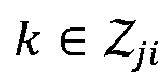
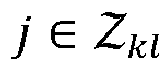
- the base station 131 may relax the above constraints by considering as candidate resources those resources that fulfill the following requirements: the UE ( i ) 101 is sufficiently far away from all UEs ( l ) 231 scheduled to receive on the given radio resource, excluding those toward which it can form nulls, i.e., l ⁇ Z ij , as well as those which can form nulls toward UE ( i ) 101, i.e., i ⁇ Z lk ; the UE ( j ) 203 is sufficiently far away from all UEs ( k ) 233 scheduled to transmit on the given radio resource, excluding those toward which it can form nulls, i.e., k ⁇ Z ji , as well as those which can form nulls toward UE ( j ) 203
- the UE ( i ) 101 can form a null toward the UE ( m ) 205a when transmitting to the UE ( j ) 203, i.e., m ⁇ Z ij .
- the UE ( i ) 101 may be allowed to transmit on a resource on which the UE ( m ) 205a is receiving, without causing interference to the UE ( m ) 205a.
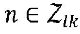
- the UE ( l ) 231 can form a null toward the UE ( n ) 235a when receiving from the UE ( k ) 233, i.e., n ⁇ Z lk .
- the UE ( l ) 231 may be allowed to receive on a resource on which the UE ( n ) 235a is transmitting, without suffering interference from the UE ( n ) 235a.
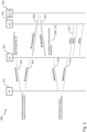
- Figure 3 shows a schematic diagram summarizing a procedure 300 for allocating sidelink radio resources according to an embodiment.
- the procedure 300 shown in figure 3 comprises the following steps.
- the UE ( i ) 101 reports a list of neighbor (i.e., strongest detected) UEs ( M i ) to its serving base station 131. Together with the IDs of the UEs, location information and signal strengths observed from these UEs can also be reported if available at the UE ( i ) 101.
- the UE ( i ) 101 receives instructions from the base station 131 about the RS scheme to use, which includes RS symbols and their allocation in time, frequency, beam and/or antenna.
- RS reference signal
- a third step 305, 307 of RS transmission and/or reception the UE ( i ) 101 transmits or receives RSs based on the assigned RS scheme.
- the UE ( i ) 101 can estimate the MIMO channel matrix H ij to UE ( j ) 331, as well as the MIMO channel matrix H im to each UE ( m ) of a subset ( N i ) 333 of active neighbor UEs ( m ⁇ N i ⁇ M i ), based on the RS sequences received from UE ( j ) 331, and the RS sequences received from each UE ( m ) of the subset ( N i ) 333 of active neighbor UEs. If the UEs support beamforming, this phase also includes the selection of the best set of beams.
- the UE ( i ) 101 determines a nulling set Z ij for UE ( j ) 331, as well as a nulling set Z im for each UE ( m ) of the subset ( N i ) 333 of active neighbor UEs. This can be implemented via beamforming and/or MIMO precoding/postcoding in both transmitting and/or receiving direction by the UE ( i ) 101.
- the UE ( i ) 101 reports its nulling sets ( Z ij and Z im , m ⁇ N i ) to its serving base station 131.
- This information includes the user IDs, time, frequency and spatial resources to which interference mitigation applies and may also include information about the expected interference level (including beamforming and/or precoding/postcoding), channel measurements (complex-valued or power levels), etc. In case UEs are served by different base stations, this information needs to be exchanged between the base stations (e.g., over the backhaul network).
- the sidelink scheduler i.e., the base station 131, uses the reported nulling sets when determining candidate resources for link scheduling.
- the scheduling decision is transmitted to the UE ( i ) 101 via a sidelink grant.
- the UE ( i ) 101 transmits the sidelink data to the UE ( j ) 331 using beamforming/MIMO processing.
- W ji R denotes the beamforming/postcoding matrix (digital, analog, or hybrid) used by the UE ( j ) 331 to receive data from the
- the first term inside the brackets is the desired signal
- the second term represents interference from other transmitters ( k )
- the third term represents interference caused by transmissions from the UE ( i ) 101 to other UEs ( m ).
- the procedure shown in figure 3 is described from the perspective of the UE ( i ) 101, meaning that this is the UE measuring and reporting information to the network entity 131 and receiving instructions from the network entity 131 for transmission to another UE ( j ) 331.
- the same procedure of measurement reporting is followed by the UE ( j ) 331 and other UEs as well, so that RS assignments and sidelink grants are assigned by the network entity 131 on the basis of the information provided by all involved UEs.
- the instructions of the network entity 131 can be provided in the following form according to an embodiment: "RS group index", determining the group (family) of RS sets to which the UE ( i ) 101 and its own RS scheme belongs; and/or "RS user index", defining the particular RS scheme of the UE ( i ) 101 within the group.
- the UE ( i ) 101 has full information about its own RS scheme, as well as the RS schemes of neighbor UEs, whose channel it needs to estimate. These are implicitly given by the remaining user indices of the RS schemes defined by the group index.
- the subset of active neighbor UEs (corresponding to the channels to be detected by the UE) is denoted by N i N i ⁇ M i .
- the RS index must include a sufficiently large number of different RS schemes, allowing for the estimation of a sufficiently large number of channels to different UEs. Out of these UEs, the particular UEs which will be included into the final beamforming/MIMO transmission or reception group will be selected.
- the same RS group index should be used only in sufficiently separated geographical areas. However, the areas in which different RS group indices are simultaneously used can be under certain conditions also overlapping. This implies that RSs defined by (some of the) RS group indices may coexist, e.g., if they are separated in time, frequency, beam, antenna or code.
- the UE can use the instructed RS scheme until it receives a new instruction by the base station.
- the decision updates of the base station are based on measurements ( M i ) and location information provided by the UE and all other UEs to the base station.
- RS assignments can be jointly agreed by base stations before being provided to UEs.
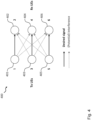
- Figure 4 illustrates an exemplary communication network 400 comprising three links (transmitter/receiver pairs), wherein the communication network 400 comprises three vehicles 401, 403, 405 as transmitters and three vehicles 402, 404, 406 as receivers and wherein each vehicle comprises three antennas.
- the same radio resource can be allocated to links (1,2) and (3,4), or to links (3,4) and (5,6), but not to links (1,2) and (5,6), since the vehicle (1) 401 is unable to null the vehicle (6) 406 and vice versa.
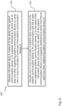
- Figure 5 shows a diagram illustrating a corresponding method 500 for operating a sidelink communication device ( i ) 101, according to an embodiment, which is configured to communicate with at least one neighboring sidelink communication device ( j ).
- the method 500 comprises the following steps: determining 501, in particular on the basis of one or more sidelink reference signals exchanged between the sidelink communication device ( i ) 101 and at least one other neighboring sidelink communication device ( k ), a measure for the ability of the sidelink communication device ( i ) 101 to suppress interference to and/or from the at least one other neighboring sidelink communication device ( k ) using one or more of a plurality of antennas of the sidelink communication device ( i ) 101; transmitting 503 to a network entity 131, in particular a base station, information about the measure for the ability of the sidelink communication device ( i ) 101 to suppress interference to and/or from the at least one other neighboring sidelink communication device ( k ); and communicating 505 using one or more of the plurality of antennas with the at least one neighboring sidelink communication device ( j ) using one or more sidelink radio resources of a plurality of sidelink radio resources allocated by the network entity 131.
- Figure 6 shows a diagram illustrating a corresponding method 600 for allocating sidelink radio resources for sidelink communication between a sidelink communication device ( i ) 101 and at least one neighboring sidelink communication device ( j ).
- the method 600 comprises the following steps: receiving 601 information about a measure for the ability of the sidelink communication device ( i ) 101 to suppress interference to and/or from at least one other neighboring sidelink communication device ( k ) using one or more of a plurality of antennas of the sidelink communication device ( i ) 101; and allocating 603 one or more of a plurality of sidelink radio resources to the sidelink communication device ( i ) 101 for communication with the at least one neighboring sidelink communication device ( j ) on the basis of the information about the measure for the ability of the sidelink communication device ( i ) 101 to suppress interference to and/or from the at least one other neighboring sidelink communication device ( k ).
Landscapes
- Engineering & Computer Science (AREA)
- Computer Networks & Wireless Communication (AREA)
- Signal Processing (AREA)
- Quality & Reliability (AREA)
- Mobile Radio Communication Systems (AREA)
Description
- In general, the present invention relates to the field of wireless communication. More specifically, the present invention relates to devices and methods for multi-antenna sidelink scheduling in a V2X communication network, in particular a sidelink communication device and a network entity for allocating sidelink radio resources as well as corresponding methods.
- V2X (Vehicle-to-Everything) services can be provided directly via a so-called PC5 interface (also known as sidelink or D2D communication) and/or indirectly via an LTE-Uu interface (also known as uplink/downlink), as specified in 3GPP TS 36.300 V14.2.0, "LTE; Evolved Universal Terrestrial Radio Access (E-UTRA) and Evolved Universal Terrestrial Radio Access Network (E-UTRAN); Overall description; ". Support of V2X services via the PC5 interface is provided by V2X sidelink communication, which is a communication mode in which User Equipments (UEs) such as vehicles can communicate with each other directly via the PC5 interface. This communication mode is supported when the UE is served by E-UTRAN and when the UE is outside of E-UTRA coverage.
- A UE supporting V2X sidelink communication can operate in two modes for sidelink radio resource allocation: in a first mode, known as scheduled resource allocation, a UE requests radio resources from a base station, and the base station allocates dedicated radio resources to the UE. In a second mode, known as autonomous resource selection, the UE on its own selects radio resources from (pre)configured resource pools.
- In the scheduled resource allocation mode, the UEs report their locations to the base station. Having no sidelink channel knowledge, the sidelink scheduler (e.g., a base station) is forced to allocate orthogonal resources (in time and/or frequency) to nearby UEs, in order to prevent mutual interference.
- However, transmissions from nearby UEs may not need to be orthogonalized by the sidelink scheduler if the UEs have multiple antennas. In other words, a radio resource can be reused by nearby transmissions if the UEs can make use of multi-antenna transmission techniques to mitigate interference.
- In light of the above, there is a need for improved devices and methods for multi-antenna sidelink communication, allowing for more spectrally efficient scheduling of sidelink transmissions.
-
GB2500392 -
WO2017/218782 describes high order multiple input, multiple output (MIMO) operations in which a user equipment (UE), configured with at least one normal performance receiver chain and at least one low-performance, low-complexity diversity receiver chain, signals a capabilities indicator identifying existence of the low-performance diversity receivers.WO2012/162788 describes devices and methods are provided for device-assisted interference management in heterogeneous wireless network environments. - The present invention is defined in the appended claims. It is an object of the invention to provide improved devices and methods for multi-antenna sidelink communication, allowing for more spectrally efficient scheduling of sidelink transmissions.
- The foregoing and other objects are achieved by the subject matter of the independent claims. Further implementation forms are apparent from the dependent claims, the description and the figures.
- The invention can be implemented in hardware and/or software.
- Further embodiments of the invention will be described with respect to the following figures, wherein:
-
Figure 1 shows a schematic diagram illustrating a sidelink communication device with a network entity; -
Figure 2 shows a schematic diagram illustrating a transmit nulling set and a receive nulling set formed by a sidelink communication device; -
Figure 3 shows a schematic diagram summarizing a procedure for allocating sidelink radio resources; -
Figure 4 shows a schematic diagram illustrating an exemplary communication network; -
Figure 5 shows a diagram illustrating a method for operating a sidelink communication device; and -
Figure 6 shows a diagram illustrating a method for allocating sidelink resources for sidelink communication. - In the various figures, identical reference signs will be used for identical or at least functionally equivalent features.
- In the following description, reference is made to the accompanying drawings, which form part of the disclosure, and in which are shown, by way of illustration, specific aspects in which the present invention may be placed. It will be appreciated that other aspects may be utilized and structural or logical changes may be made without departing from the scope of the present invention. The following detailed description, therefore, is not to be taken in a limiting sense, as the scope of the present invention is defined by the appended claims. Embodiments and examples not falling within the scope of the claims are for illustrative purposes and considered useful for understanding the invention.
- For instance, it will be appreciated that a disclosure in connection with a described method may also hold true for a corresponding device or system configured to perform the method and vice versa. For example, if a specific method step is described, a corresponding device may include a unit to perform the described method step, even if such unit is not explicitly described or illustrated in the figures.
- Moreover, in the following detailed description as well as in the claims, embodiments with different functional blocks or processing units are described, which are connected with each other or exchange signals. It will be appreciated that the present invention covers embodiments as well, which include additional functional blocks or processing units that are arranged between the functional blocks or processing units of the embodiments described below.
- Finally, it is understood that the features of the various exemplary aspects described herein may be combined with each other, unless specifically noted otherwise.
- As will be described in more detail in the following, embodiments of the invention relate to a V2X communication network comprising a sidelink communication device and a network entity, which allow for a significant increase in sidelink radio resource reuse.
- Multi-antenna transmission techniques, such as beamforming or MIMO (Multiple-Input Multiple-Output), are powerful tools for interference mitigation and SINR (Signal-to-Interference-plus-Noise Ratio) enhancement. The potential of MIMO processing (e.g., through data precoding and/or postcoding) scales with the number of available antennas: compared to single-antenna transmission, SINR gains of above 20 dB can be achieved by using, e.g., up to 16 transmitting and receiving antennas. Furthermore, depending on the particular precoding and/or postcoding scheme, available antennas can be used for interference mitigation, diversity and/or data multiplexing gains.
- The embodiments of the present invention can combine beamforming and/or MIMO schemes with sidelink scheduling decisions taken by a network entity in the form of a sidelink scheduler: given two (or more) sidelink communication devices for data transmission, e.g., User Equipments (UEs), a sidelink scheduler such as a base station can determine whether the same radio resource (i.e., time and/or frequency channel) may be used by both UEs. Instead of reporting the full Channel State Information (CSI) to the base station, which would incur considerable control signaling overhead, the UEs can report information about their ability to use multi-antenna transmission/reception to cancel interference to/from nearby UEs, as will be described in more detail in the following.
-
Figure 1 shows a schematic diagram illustrating acommunication network 100 comprising a sidelink communication device (i) 101, in particular a multi-antenna sidelink communication device, according to an embodiment, and anetwork entity 131, according to an embodiment. The sidelink communication device (i) 101 is configured to communicate with neighboring sidelink communication devices (not shown infigure 1 ) via a sidelink communication channel, and with thenetwork entity 131 via an uplink/downlink communication channel. - In the embodiment shown in
figure 1 , the sidelink communication device (i) 101 could be implemented in the form of a user entity such as a mobile phone or a vehicle or a communication module of a vehicle. However, it will be appreciated that embodiments of the invention apply to sidelink communication devices other than mobile phones or vehicles as well. In an exemplary embodiment, thenetwork entity 131 can be, for instance, a base station. - As illustrated in
figure 1 , the sidelink communication device (i) 101 comprises atransceiver 103 comprising a plurality of antennas and configured to communicate with at least one neighboring sidelink communication device (j) using one or more sidelink radio resources of a plurality of sidelink radio resources allocated by thenetwork entity 131. - Furthermore, the sidelink communication device (i) 101 comprises a
processor 105. As will be described in more detail in the context offigure 2 , theprocessor 105 is configured to determine a measure for the ability of the sidelink communication device (i) 101 to suppress interference to and/or from at least one other neighboring sidelink communication device (k) using one or more of the plurality of antennas. - As can be taken from
figure 1 , thenetwork entity 131 comprises atransceiver 133 configured to receive information about the measure for the ability of the sidelink communication device (i) 101 to suppress interference to and/or from at least one other neighboring sidelink communication device (k) using one or more of a plurality of antennas of the sidelink communication device (i) 101. - The
network entity 131 further comprises aprocessor 135 configured to allocate one or more of a plurality of sidelink radio resources to the sidelink communication device (i) 101 for communication with the at least one neighboring sidelink communication device (j) on the basis of the information about the measure for the ability of the sidelink communication device (i) 101 to suppress interference to and/or from the at least one other neighboring sidelink communication device (k). - More details about sidelink radio resource allocation for sidelink communication between the sidelink communication device (i) 101 and at least one neighboring sidelink communication device (j) will be described in the following.
- First, the
transceiver 133 of thenetwork entity 131 is configured to receive information about an identity, a signal strength and/or a location of the at least one other neighboring sidelink communication device (k) from the sidelink communication device (i) 101. - After the reception, the
processor 135 of thenetwork entity 131 is configured to determine one or more sidelink reference signals and/or allocate one or more sidelink radio resources for exchanging the one or more sidelink reference signals on the basis of the identity, the signal strength and/or the location of the at least one other neighboring sidelink communication device (k), and thetransceiver 133 is further configured to transmit to the sidelink communication device (i) 101 information about the one or more sidelink reference signals and/or information about the one or more sidelink radio resources for exchanging the one or more sidelink reference signals with the at least one other neighboring sidelink communication device (k). - The
transceiver 103 of thesidelink communication device 101 is configured to receive from thenetwork entity 131 information about the one or more sidelink reference signals and/or information about one or more sidelink radio resources for exchanging the one or more sidelink reference signals with the at least one other neighboring sidelink communication device (k). More details about the reference signal assignment will be further discussed in the following embodiments. - Furthermore, the
transceiver 103 of thesidelink communication device 101 is configured to transmit the one or more sidelink reference signals on the basis of the information received from thenetwork entity 131 to the at least one other neighboring sidelink communication device (k). Thetransceiver 103 is also configured to receive the one or more sidelink reference signals from the at least one other neighboring sidelink communication device (k). - On the basis of the one or more sidelink reference signals exchanged with the at least one other neighboring sidelink communication device (k), the
processor 105 of the sidelink communication device (i) 101 determines one or more physical properties of the sidelink communication channel between at least one of the plurality of antennas of the sidelink communication device (i) 101 and at least one of a plurality of antennas of the at least one other neighboring sidelink communication device (k). - As already mentioned above, the
processor 105 is configured to determine a measure for the ability of the sidelink communication device (i) 101 to suppress interference to and/or from the at least one other neighboring sidelink communication device (k) on the basis of the one or more physical properties of the sidelink communication channel, in particular by means of signal processing of one or more signals from the plurality of antennas of the sidelink communication device (i) 101. - After the above determination by the
processor 105, thetransceiver 103 of the sidelink communication device (i) 101 can transmit to thenetwork entity 131 information about the measure for the ability of the sidelink communication device (i) 101 to suppress interference, in particular for allocation of the one or more sidelink radio resources by thenetwork entity 131. - Upon receiving the information, the
network entity 131 can allocate one or more of the plurality of sidelink radio resources to the sidelink communication device (i) 101 for communication with the at least one neighboring sidelink communication device (j) on the basis of the information about the measure for the ability of the sidelink communication device (i) 101 to suppress interference to and/or from the at least one other neighboring sidelink communication device (k). - As already mentioned, the sidelink communication device (i) 101 can determine a measure for its ability to suppress interference to and/or from at least one other neighboring sidelink communication device (k) using one or more of the plurality of antennas and then transmit this measure to the
network entity 131 for the purpose of sidelink radio resource allocation. As will be illustrated under further reference tofigure 2 , the measure for the ability to suppress interference can correspond to a set of one or more neighboring sidelink communication devices toward which the sidelink communication device (i) 101 can form "nulls" (e.g., in its radiation pattern) when transmitting to and/or receiving from the sidelink communication device (j). This set of one or more neighboring sidelink communication devices is referred to herein as a "nulling set". - More specifically, in an embodiment, the sidelink communication device (i) 101 (herein also referred to as user equipment or UE) can inform the network entity 131 (herein also referred to as base station) about a set of one or more nearby UEs (m) 205a-d toward which it can form nulls when transmitting to a UE (j) 203. Such a set is referred to as transmit nulling set

- Similarly, a sidelink communication device or a UE (l) 231 can inform the
network entity 131, i.e., the base station, about a set of one or more nearby UEs (n) 235a-d toward which it can form nulls when receiving from a UE (k) 233. Such a set is referred to as receive nulling set


figure 2 . - In general, the sets


- To minimize interference, the
base station 131, acting as sidelink scheduler, can ensure sufficient physical separation between UEs transmitting/receiving on any given radio resource. Thus, upon receiving a request for resources from UE (i) 101 to transmit to UE (j) 203 on link (i,j), thebase station 131 may consider a set of candidate resources, wherein each candidate resource fulfills the following requirements: the UE (i) 101 is sufficiently far away from all UEs (l) 231 scheduled to receive on the given radio resource; the UE (j) 203 is sufficiently far away from all UEs (k) 233 scheduled to transmit on the given radio resource. - In such case, however, the
base station 131 does not take advantage of the ability of the UEs to mitigate interference by means of multi-antenna transmission/reception, which may thus result in a small set of candidate resources, especially when the network is under high load. - On the other hand, if the sidelink scheduler (i.e., base station) 131 is aware of the nulling sets

base station 131 may relax the above constraints by considering as candidate resources those resources that fulfill the following requirements: the UE (i) 101 is sufficiently far away from all UEs (l) 231 scheduled to receive on the given radio resource, excluding those toward which it can form nulls, i.e.,

- As shown in
figure 2 , the UE (i) 101 can form a null toward the UE (m) 205a when transmitting to the UE (j) 203, i.e.,
- Similarly, the UE (l) 231 can form a null toward the UE (n) 235a when receiving from the UE (k) 233, i.e.,
-
Figure 3 shows a schematic diagram summarizing aprocedure 300 for allocating sidelink radio resources according to an embodiment. Theprocedure 300 shown infigure 3 comprises the following steps. - In a
first step 301 of measurement reporting, based on own measurements, the UE (i) 101 reports a list of neighbor (i.e., strongest detected) UEs (
serving base station 131. Together with the IDs of the UEs, location information and signal strengths observed from these UEs can also be reported if available at the UE (i) 101. - In a
second step 303 of reference signal (RS) assignment, the UE (i) 101 receives instructions from thebase station 131 about the RS scheme to use, which includes RS symbols and their allocation in time, frequency, beam and/or antenna. - In a
third step - In a fourth step 309 of channel estimation, the UE (i) 101 can estimate the MIMO channel matrix H ij to UE (j) 331, as well as the MIMO channel matrix H im to each UE (m) of a subset (


- In a fifth step 311 of nulling set determination, based on these measurements and -if provided- knowledge of locations of the UEs, the UE (i) 101 determines a nulling set


- In a
sixth step 313 of nulling set reporting, the UE (i) 101 reports its nulling sets (

serving base station 131. This information includes the user IDs, time, frequency and spatial resources to which interference mitigation applies and may also include information about the expected interference level (including beamforming and/or precoding/postcoding), channel measurements (complex-valued or power levels), etc. In case UEs are served by different base stations, this information needs to be exchanged between the base stations (e.g., over the backhaul network). - In a
seventh step 315 of sidelink resource allocation, the sidelink scheduler, i.e., thebase station 131, uses the reported nulling sets when determining candidate resources for link scheduling. The scheduling decision is transmitted to the UE (i) 101 via a sidelink grant. - In a
final step 317 of sidelink data transmission, the UE (i) 101 transmits the sidelink data to the UE (j) 331 using beamforming/MIMO processing. In the general case of transmit and receive side beamforming and MIMO processing, the MIMO signal (y j ) received by the UE (j) 331, which has been scheduled to receive a data symbol/vector (s ij ) from the UE (i) 101 on a particular radio resource, will be given by


- The first term inside the brackets is the desired signal, the second term represents interference from other transmitters (k), and the third term represents interference caused by transmissions from the UE (i) 101 to other UEs (m). By performing beamforming/MIMO processing, the interference (second and third terms) can be mitigated.
- The procedure shown in
figure 3 is described from the perspective of the UE (i) 101, meaning that this is the UE measuring and reporting information to thenetwork entity 131 and receiving instructions from thenetwork entity 131 for transmission to another UE (j) 331. The same procedure of measurement reporting is followed by the UE (j) 331 and other UEs as well, so that RS assignments and sidelink grants are assigned by thenetwork entity 131 on the basis of the information provided by all involved UEs. - In order for the UE (i) 101 to be informed about the RS schemes used by its nearby UEs (i.e., the channels it needs to estimate), the instructions of the
network entity 131 can be provided in the following form according to an embodiment: "RS group index", determining the group (family) of RS sets to which the UE (i) 101 and its own RS scheme belongs; and/or "RS user index", defining the particular RS scheme of the UE (i) 101 within the group. - Based on these two indices, the UE (i) 101 has full information about its own RS scheme, as well as the RS schemes of neighbor UEs, whose channel it needs to estimate. These are implicitly given by the remaining user indices of the RS schemes defined by the group index.
- Not all RS user indices need to be used by all neighbor UEs at all times. The subset of active neighbor UEs (corresponding to the channels to be detected by the UE) is denoted by

- Naturally, the number (and exact IDs) of the UEs which will form the beamforming/MIMO transmission or reception group is not known before or during channel estimation. Therefore, the RS index must include a sufficiently large number of different RS schemes, allowing for the estimation of a sufficiently large number of channels to different UEs. Out of these UEs, the particular UEs which will be included into the final beamforming/MIMO transmission or reception group will be selected.
- In order to avoid interference on RS symbols, the same RS group index should be used only in sufficiently separated geographical areas. However, the areas in which different RS group indices are simultaneously used can be under certain conditions also overlapping. This implies that RSs defined by (some of the) RS group indices may coexist, e.g., if they are separated in time, frequency, beam, antenna or code.
- The UE can use the instructed RS scheme until it receives a new instruction by the base station. The decision updates of the base station are based on measurements (

- In order to allow for channel estimation between UEs served by different base stations (cell edge), RS assignments can be jointly agreed by base stations before being provided to UEs.
-
Figure 4 illustrates anexemplary communication network 400 comprising three links (transmitter/receiver pairs), wherein thecommunication network 400 comprises threevehicles vehicles - The nulling sets between these vehicles are provided as follows:


- In this case, the same radio resource can be allocated to links (1,2) and (3,4), or to links (3,4) and (5,6), but not to links (1,2) and (5,6), since the vehicle (1) 401 is unable to null the vehicle (6) 406 and vice versa.
-
Figure 5 shows a diagram illustrating acorresponding method 500 for operating a sidelink communication device (i) 101, according to an embodiment, which is configured to communicate with at least one neighboring sidelink communication device (j). - The
method 500 comprises the following steps: determining 501, in particular on the basis of one or more sidelink reference signals exchanged between the sidelink communication device (i) 101 and at least one other neighboring sidelink communication device (k), a measure for the ability of the sidelink communication device (i) 101 to suppress interference to and/or from the at least one other neighboring sidelink communication device (k) using one or more of a plurality of antennas of the sidelink communication device (i) 101; transmitting 503 to anetwork entity 131, in particular a base station, information about the measure for the ability of the sidelink communication device (i) 101 to suppress interference to and/or from the at least one other neighboring sidelink communication device (k); and communicating 505 using one or more of the plurality of antennas with the at least one neighboring sidelink communication device (j) using one or more sidelink radio resources of a plurality of sidelink radio resources allocated by thenetwork entity 131. -
Figure 6 shows a diagram illustrating acorresponding method 600 for allocating sidelink radio resources for sidelink communication between a sidelink communication device (i) 101 and at least one neighboring sidelink communication device (j). - The
method 600 comprises the following steps: receiving 601 information about a measure for the ability of the sidelink communication device (i) 101 to suppress interference to and/or from at least one other neighboring sidelink communication device (k) using one or more of a plurality of antennas of the sidelink communication device (i) 101; and allocating 603 one or more of a plurality of sidelink radio resources to the sidelink communication device (i) 101 for communication with the at least one neighboring sidelink communication device (j) on the basis of the information about the measure for the ability of the sidelink communication device (i) 101 to suppress interference to and/or from the at least one other neighboring sidelink communication device (k). - While a particular feature or aspect of the disclosure may have been disclosed with respect to only one of several implementations or embodiments, such feature or aspect may be combined with one or more other features or aspects of the other implementations or embodiments as may be desired and advantageous for any given or particular application. Furthermore, to the extent that the terms "include", "have", "with", or other variants thereof are used in either the detailed description or the claims, such terms are intended to be inclusive in a manner similar to the term "comprise". Also, the terms "exemplary", "for example" and "e.g." are merely meant as an example, rather than the best or optimal. The terms "coupled" and "connected", along with derivatives may have been used. It should be understood that these terms may have been used to indicate that two elements cooperate or interact with each other regardless of whether they are in direct physical or electrical contact, or they are not in direct contact with each other.
- Although specific aspects have been illustrated and described herein, it will be appreciated by those of ordinary skill in the art that a variety of alternate and/or equivalent implementations may be substituted for the specific aspects shown and described without departing from the scope of the present disclosure. This application is intended to cover any adaptations or variations of the specific aspects discussed herein.
- Although the elements in the following claims are recited in a particular sequence with corresponding labeling, unless the claim recitations otherwise imply a particular sequence for implementing some or all of those elements, those elements are not necessarily intended to be limited to being implemented in that particular sequence.
- Many alternatives, modifications, and variations will be apparent to those skilled in the art in light of the above teachings. Of course, those skilled in the art readily recognize that there are numerous applications of the invention beyond those described herein. While the present invention has been described with reference to one or more particular embodiments, those skilled in the art recognize that many changes may be made thereto without departing from the scope of the present invention. It is therefore to be understood that within the scope of the appended claims and their equivalents, the invention may be practiced otherwise than as specifically described herein.
- The project leading to this application has received funding from the European Union's Horizon 2020 research and innovation programme under grant agreement No 761510.
Claims (7)
- A sidelink communication device (i, 101) comprising:a transceiver (103) comprising a plurality of antennas and configured to communicate using one or more of the plurality of antennas with at least one neighboring sidelink communication device (j) using one or more sidelink radio resources of a plurality of sidelink radio resources allocated by a network entity (131); anda processor (105) configured to determine a measure for the ability of the sidelink communication device (i, 101) to suppress at least one of interference to at least one other neighboring sidelink communication device (k) and interference from the at least one other neighboring sidelink communication device (k) using one or more of the plurality of antennas;wherein the transceiver (103) is further configured to transmit to the network entity (131) information about the measure for the ability of the sidelink communication device (i, 101) to suppress at least one of interference to the at least one other neighboring sidelink communication device (k) and interference from the at least one other neighboring sidelink communication device (k), for allocation of the one or more sidelink radio resources by the network entity (131);characterized in that the processor (105) is configured to determine, on the basis of the one or more sidelink reference signals exchanged between the sidelink communication device (i, 101) and the at least one other neighboring sidelink communication device (k), one or more physical properties of the sidelink communication channel between at least one of the plurality of antennas of the sidelink communication device (i, 101) and at least one of a plurality of antennas of the at least one other neighboring sidelink communication device (k); and wherein the processor (105) is further configured to determine the measure for the ability of the sidelink communication device (i, 101) to suppress at least one of interference to the at least one other neighboring sidelink communication device (k) and interference from the at least one other neighboring sidelink communication device (k) on the basis of the one or more physical properties of the sidelink communication channel.
- The sidelink communication device (i, 101) of claim 1, wherein the measure for the ability to suppress at least one of interference to the at least one other neighboring sidelink communication device (k) and interference from the at least one other neighboring sidelink communication device (k) is determined on the basis of one or more sidelink reference signals exchanged between the sidelink communication device (i, 101) and the at least one other neighboring sidelink communication device (k).
- The sidelink communication device (i, 101) of claim 1 or 2, wherein the transceiver (103) is further configured to transmit to the network entity (131) information about at least one of an identity, a signal strength and a location of the at least one other neighboring sidelink communication device (k).
- The sidelink communication device (i, 101) of any one of the preceding claims, wherein the transceiver (103) is further configured to receive from the network entity (131) at least one of information about the one or more sidelink reference signals and information about one or more sidelink radio resources for exchanging the one or more sidelink reference signals with the at least one other neighboring sidelink communication device (k).
- The sidelink communication device (i, 101) of claim 4, wherein the transceiver (103) is further configured to transmit to or receive from the at least one other neighboring sidelink communication device (k) the one or more sidelink reference signals on the basis of the information received from the network entity (131).
- The sidelink communication device (i, 101) of any one of the preceding claims, wherein the transceiver (103) is further configured to receive from the network entity (131) radio resource allocation information specifying one or more of the plurality of sidelink radio resources allocated by the network entity (131) for communicating with the at least one neighboring sidelink communication device (j), on the basis of the information about the measure for the ability of the sidelink communication device (i, 101) to suppress at least one of interference to the at least one other neighboring sidelink communication device (k) and interference from the at least one other neighboring sidelink communication device (k).
- A method (500) for operating a sidelink communication device (i, 101) configured to communicate with at least one neighboring sidelink communication device (j), wherein the method (500) comprises:determining (501), on the basis of one or more sidelink reference signals exchanged between the sidelink communication device (i, 101) and at least one other neighboring sidelink communication device (k), a measure for the ability of the sidelink communication device (i, 101) to suppress at least one of interference to the at least one other neighboring sidelink communication device (k) and interference from the at least one other neighboring sidelink communication device (k) using one or more of a plurality of antennas of the sidelink communication device (i, 101);transmitting (503) to a network entity (131), information about the measure for the ability of the sidelink communication device (i, 101) to suppress at least one of interference to the at least one other neighboring sidelink communication device (k) and interference from the at least one other neighboring sidelink communication device (k); andcommunicating (505) using one or more of the plurality of antennas with the at least one neighboring sidelink communication device (j) using one or more sidelink radio resources of a plurality of sidelink radio resources allocated by the network entity (131);characterized by:determining, on the basis of the one or more sidelink reference signals exchanged between the sidelink communication device (i, 101) and the at least one other neighboring sidelink communication device (k), one or more physical properties of the sidelink communication channel between at least one of the plurality of antennas of the sidelink communication device (i, 101) and at least one of a plurality of antennas of the at least one other neighboring sidelink communication device (k); anddetermining the measure for the ability of the sidelink communication device (i, 101) to suppress at least one of interference to the at least one other neighboring sidelink communication device (k) and interference from the at least one other neighboring sidelink communication device (k) on the basis of the one or more physical properties of the sidelink communication channel.
Applications Claiming Priority (1)
| Application Number | Priority Date | Filing Date | Title |
|---|---|---|---|
| PCT/EP2018/053565 WO2019158185A1 (en) | 2018-02-13 | 2018-02-13 | Devices and methods for multi-antenna sidelink scheduling |
Publications (2)
| Publication Number | Publication Date |
|---|---|
| EP3738368A1 EP3738368A1 (en) | 2020-11-18 |
| EP3738368B1 true EP3738368B1 (en) | 2024-04-10 |
Family
ID=61244580
Family Applications (1)
| Application Number | Title | Priority Date | Filing Date |
|---|---|---|---|
| EP18705875.5A Active EP3738368B1 (en) | 2018-02-13 | 2018-02-13 | Devices and methods for multi-antenna sidelink scheduling |
Country Status (3)
| Country | Link |
|---|---|
| US (1) | US11405928B2 (en) |
| EP (1) | EP3738368B1 (en) |
| WO (1) | WO2019158185A1 (en) |
Families Citing this family (4)
| Publication number | Priority date | Publication date | Assignee | Title |
|---|---|---|---|---|
| CN110138519A (en) | 2018-02-02 | 2019-08-16 | 索尼公司 | Device and method, computer readable storage medium in wireless communication system |
| CN116405902B (en) * | 2018-08-10 | 2026-06-26 | 中兴通讯股份有限公司 | Resource allocation method and device for direct links in vehicle-to-everything (V2X) |
| CN114827957A (en) * | 2021-01-27 | 2022-07-29 | 展讯通信(上海)有限公司 | Method and device for determining auxiliary equipment, electronic equipment and storage medium |
| EP4461073A4 (en) * | 2023-04-23 | 2025-03-12 | ZTE Corporation | Resource allocation schemes for sidelink communications |
Family Cites Families (5)
| Publication number | Priority date | Publication date | Assignee | Title |
|---|---|---|---|---|
| CA2837485C (en) * | 2011-05-31 | 2018-08-28 | Blackberry Limited | Access point for device-assisted interference management in heterogeneous wireless cellular systems |
| GB2500392B (en) * | 2012-03-19 | 2014-05-14 | Broadcom Corp | Filtering |
| US20180115873A1 (en) * | 2015-03-19 | 2018-04-26 | Nec Corporation | Apparatus and method for proximity-based service communication |
| WO2017176088A1 (en) * | 2016-04-08 | 2017-10-12 | 엘지전자 주식회사 | Method for setting resource for device-to-device communication in wireless communication system, and apparatus for same |
| WO2017218782A1 (en) * | 2016-06-16 | 2017-12-21 | Qualcomm Incorporated | Low complexity higher order mimo |
-
2018
- 2018-02-13 EP EP18705875.5A patent/EP3738368B1/en active Active
- 2018-02-13 WO PCT/EP2018/053565 patent/WO2019158185A1/en not_active Ceased
-
2020
- 2020-08-13 US US16/992,807 patent/US11405928B2/en active Active
Also Published As
| Publication number | Publication date |
|---|---|
| US11405928B2 (en) | 2022-08-02 |
| WO2019158185A1 (en) | 2019-08-22 |
| US20200374891A1 (en) | 2020-11-26 |
| EP3738368A1 (en) | 2020-11-18 |
Similar Documents
| Publication | Publication Date | Title |
|---|---|---|
| JP6798006B2 (en) | How to send an uplink | |
| EP3493427B1 (en) | Providing space division multiple access in a wireless network | |
| US10999872B2 (en) | Random access technique in mobile communication system using beamforming | |
| EP4319413A2 (en) | Over-the-air signal assisted interference cancellation or suppression | |
| US11405928B2 (en) | Devices and methods for multi-antenna sidelink scheduling | |
| EP2467965B1 (en) | A method for operating a radio station in a mobile network | |
| US7965785B2 (en) | Uplink multiple-input-multiple-output (MIMO) and cooperative MIMO transmissions | |
| KR101387532B1 (en) | Method of transmitting Feedback Information for performing Collaborative MIMO | |
| JP5536274B2 (en) | Method and apparatus for transmitting terminal data in distributed antenna system | |
| JP7022762B2 (en) | User equipment, base stations, wireless communication methods and systems | |
| CN105764151B (en) | Communication method and device | |
| CN109155656B (en) | Method, system and device for selecting wave beams | |
| EP4030675B1 (en) | Method of frequency resource allocation | |
| EP3314972B1 (en) | Method for accessing a network by using a virtual ue scheme and corresponding ue | |
| KR20110101033A (en) | Apparatus and method for controlling intercell interference | |
| WO2017136732A1 (en) | Beamforming common channels in 5g new radio | |
| KR20100057857A (en) | Method and apparatus for removing interference between signals received by several mobile stations | |
| WO2022079188A1 (en) | Iterative transmit refinement | |
| KR20150009045A (en) | method and apparatus for measurement of MU-MIMO interference in a cellular system | |
| WO2016059960A1 (en) | Apparatus | |
| US8649796B2 (en) | Method and device for determining a cooperation area | |
| JP6210158B2 (en) | Wireless communication system, base station, mobile station, transmission method and demodulation method | |
| WO2011042045A1 (en) | Reservation of common control channel elements for dedicated signalling | |
| KR102449735B1 (en) | Method and apparatus for transmitting pilot in multi-antenna communication system, and method and apparatus for allocating pilot in multi-antenna communication system | |
| KR101394608B1 (en) | Mobile communication system for supporting multiple input and multiple output and method for allocating precoding matrix in the same |
Legal Events
| Date | Code | Title | Description |
|---|---|---|---|
| STAA | Information on the status of an ep patent application or granted ep patent |
Free format text: STATUS: UNKNOWN |
|
| STAA | Information on the status of an ep patent application or granted ep patent |
Free format text: STATUS: THE INTERNATIONAL PUBLICATION HAS BEEN MADE |
|
| PUAI | Public reference made under article 153(3) epc to a published international application that has entered the european phase |
Free format text: ORIGINAL CODE: 0009012 |
|
| STAA | Information on the status of an ep patent application or granted ep patent |
Free format text: STATUS: REQUEST FOR EXAMINATION WAS MADE |
|
| 17P | Request for examination filed |
Effective date: 20200812 |
|
| AK | Designated contracting states |
Kind code of ref document: A1 Designated state(s): AL AT BE BG CH CY CZ DE DK EE ES FI FR GB GR HR HU IE IS IT LI LT LU LV MC MK MT NL NO PL PT RO RS SE SI SK SM TR |
|
| AX | Request for extension of the european patent |
Extension state: BA ME |
|
| DAV | Request for validation of the european patent (deleted) | ||
| DAX | Request for extension of the european patent (deleted) | ||
| STAA | Information on the status of an ep patent application or granted ep patent |
Free format text: STATUS: EXAMINATION IS IN PROGRESS |
|
| 17Q | First examination report despatched |
Effective date: 20220425 |
|
| REG | Reference to a national code |
Free format text: PREVIOUS MAIN CLASS: H04W0072040000 Ipc: H04W0072542000 Ref country code: DE Ref legal event code: R079 Ref document number: 602018067810 Country of ref document: DE Free format text: PREVIOUS MAIN CLASS: H04W0072040000 Ipc: H04W0072542000 |
|
| RIC1 | Information provided on ipc code assigned before grant |
Ipc: H04W 72/542 20230101AFI20230628BHEP |
|
| GRAP | Despatch of communication of intention to grant a patent |
Free format text: ORIGINAL CODE: EPIDOSNIGR1 |
|
| STAA | Information on the status of an ep patent application or granted ep patent |
Free format text: STATUS: GRANT OF PATENT IS INTENDED |
|
| INTG | Intention to grant announced |
Effective date: 20230904 |
|
| GRAS | Grant fee paid |
Free format text: ORIGINAL CODE: EPIDOSNIGR3 |
|
| GRAA | (expected) grant |
Free format text: ORIGINAL CODE: 0009210 |
|
| STAA | Information on the status of an ep patent application or granted ep patent |
Free format text: STATUS: THE PATENT HAS BEEN GRANTED |
|
| AK | Designated contracting states |
Kind code of ref document: B1 Designated state(s): AL AT BE BG CH CY CZ DE DK EE ES FI FR GB GR HR HU IE IS IT LI LT LU LV MC MK MT NL NO PL PT RO RS SE SI SK SM TR |
|
| REG | Reference to a national code |
Ref country code: GB Ref legal event code: FG4D |
|
| REG | Reference to a national code |
Ref country code: CH Ref legal event code: EP |
|
| REG | Reference to a national code |
Ref country code: DE Ref legal event code: R096 Ref document number: 602018067810 Country of ref document: DE |
|
| REG | Reference to a national code |
Ref country code: IE Ref legal event code: FG4D |
|
| REG | Reference to a national code |
Ref country code: LT Ref legal event code: MG9D |
|
| REG | Reference to a national code |
Ref country code: NL Ref legal event code: MP Effective date: 20240410 |
|
| REG | Reference to a national code |
Ref country code: AT Ref legal event code: MK05 Ref document number: 1676188 Country of ref document: AT Kind code of ref document: T Effective date: 20240410 |
|
| PG25 | Lapsed in a contracting state [announced via postgrant information from national office to epo] |
Ref country code: NL Free format text: LAPSE BECAUSE OF FAILURE TO SUBMIT A TRANSLATION OF THE DESCRIPTION OR TO PAY THE FEE WITHIN THE PRESCRIBED TIME-LIMIT Effective date: 20240410 |
|
| PG25 | Lapsed in a contracting state [announced via postgrant information from national office to epo] |
Ref country code: NL Free format text: LAPSE BECAUSE OF FAILURE TO SUBMIT A TRANSLATION OF THE DESCRIPTION OR TO PAY THE FEE WITHIN THE PRESCRIBED TIME-LIMIT Effective date: 20240410 |
|
| PG25 | Lapsed in a contracting state [announced via postgrant information from national office to epo] |
Ref country code: IS Free format text: LAPSE BECAUSE OF FAILURE TO SUBMIT A TRANSLATION OF THE DESCRIPTION OR TO PAY THE FEE WITHIN THE PRESCRIBED TIME-LIMIT Effective date: 20240810 |
|
| PG25 | Lapsed in a contracting state [announced via postgrant information from national office to epo] |
Ref country code: BG Free format text: LAPSE BECAUSE OF FAILURE TO SUBMIT A TRANSLATION OF THE DESCRIPTION OR TO PAY THE FEE WITHIN THE PRESCRIBED TIME-LIMIT Effective date: 20240410 |
|
| PG25 | Lapsed in a contracting state [announced via postgrant information from national office to epo] |
Ref country code: HR Free format text: LAPSE BECAUSE OF FAILURE TO SUBMIT A TRANSLATION OF THE DESCRIPTION OR TO PAY THE FEE WITHIN THE PRESCRIBED TIME-LIMIT Effective date: 20240410 Ref country code: FI Free format text: LAPSE BECAUSE OF FAILURE TO SUBMIT A TRANSLATION OF THE DESCRIPTION OR TO PAY THE FEE WITHIN THE PRESCRIBED TIME-LIMIT Effective date: 20240410 |
|
| PG25 | Lapsed in a contracting state [announced via postgrant information from national office to epo] |
Ref country code: GR Free format text: LAPSE BECAUSE OF FAILURE TO SUBMIT A TRANSLATION OF THE DESCRIPTION OR TO PAY THE FEE WITHIN THE PRESCRIBED TIME-LIMIT Effective date: 20240711 |
|
| PG25 | Lapsed in a contracting state [announced via postgrant information from national office to epo] |
Ref country code: PT Free format text: LAPSE BECAUSE OF FAILURE TO SUBMIT A TRANSLATION OF THE DESCRIPTION OR TO PAY THE FEE WITHIN THE PRESCRIBED TIME-LIMIT Effective date: 20240812 |
|
| PG25 | Lapsed in a contracting state [announced via postgrant information from national office to epo] |
Ref country code: ES Free format text: LAPSE BECAUSE OF FAILURE TO SUBMIT A TRANSLATION OF THE DESCRIPTION OR TO PAY THE FEE WITHIN THE PRESCRIBED TIME-LIMIT Effective date: 20240410 |
|
| PG25 | Lapsed in a contracting state [announced via postgrant information from national office to epo] |
Ref country code: AT Free format text: LAPSE BECAUSE OF FAILURE TO SUBMIT A TRANSLATION OF THE DESCRIPTION OR TO PAY THE FEE WITHIN THE PRESCRIBED TIME-LIMIT Effective date: 20240410 |
|
| PG25 | Lapsed in a contracting state [announced via postgrant information from national office to epo] |
Ref country code: PL Free format text: LAPSE BECAUSE OF FAILURE TO SUBMIT A TRANSLATION OF THE DESCRIPTION OR TO PAY THE FEE WITHIN THE PRESCRIBED TIME-LIMIT Effective date: 20240410 |
|
| PG25 | Lapsed in a contracting state [announced via postgrant information from national office to epo] |
Ref country code: LV Free format text: LAPSE BECAUSE OF FAILURE TO SUBMIT A TRANSLATION OF THE DESCRIPTION OR TO PAY THE FEE WITHIN THE PRESCRIBED TIME-LIMIT Effective date: 20240410 |
|
| PG25 | Lapsed in a contracting state [announced via postgrant information from national office to epo] |
Ref country code: FI Free format text: LAPSE BECAUSE OF FAILURE TO SUBMIT A TRANSLATION OF THE DESCRIPTION OR TO PAY THE FEE WITHIN THE PRESCRIBED TIME-LIMIT Effective date: 20240410 Ref country code: ES Free format text: LAPSE BECAUSE OF FAILURE TO SUBMIT A TRANSLATION OF THE DESCRIPTION OR TO PAY THE FEE WITHIN THE PRESCRIBED TIME-LIMIT Effective date: 20240410 Ref country code: BG Free format text: LAPSE BECAUSE OF FAILURE TO SUBMIT A TRANSLATION OF THE DESCRIPTION OR TO PAY THE FEE WITHIN THE PRESCRIBED TIME-LIMIT Effective date: 20240410 Ref country code: AT Free format text: LAPSE BECAUSE OF FAILURE TO SUBMIT A TRANSLATION OF THE DESCRIPTION OR TO PAY THE FEE WITHIN THE PRESCRIBED TIME-LIMIT Effective date: 20240410 Ref country code: PT Free format text: LAPSE BECAUSE OF FAILURE TO SUBMIT A TRANSLATION OF THE DESCRIPTION OR TO PAY THE FEE WITHIN THE PRESCRIBED TIME-LIMIT Effective date: 20240812 Ref country code: PL Free format text: LAPSE BECAUSE OF FAILURE TO SUBMIT A TRANSLATION OF THE DESCRIPTION OR TO PAY THE FEE WITHIN THE PRESCRIBED TIME-LIMIT Effective date: 20240410 Ref country code: NO Free format text: LAPSE BECAUSE OF FAILURE TO SUBMIT A TRANSLATION OF THE DESCRIPTION OR TO PAY THE FEE WITHIN THE PRESCRIBED TIME-LIMIT Effective date: 20240710 Ref country code: LV Free format text: LAPSE BECAUSE OF FAILURE TO SUBMIT A TRANSLATION OF THE DESCRIPTION OR TO PAY THE FEE WITHIN THE PRESCRIBED TIME-LIMIT Effective date: 20240410 Ref country code: IS Free format text: LAPSE BECAUSE OF FAILURE TO SUBMIT A TRANSLATION OF THE DESCRIPTION OR TO PAY THE FEE WITHIN THE PRESCRIBED TIME-LIMIT Effective date: 20240810 Ref country code: HR Free format text: LAPSE BECAUSE OF FAILURE TO SUBMIT A TRANSLATION OF THE DESCRIPTION OR TO PAY THE FEE WITHIN THE PRESCRIBED TIME-LIMIT Effective date: 20240410 Ref country code: GR Free format text: LAPSE BECAUSE OF FAILURE TO SUBMIT A TRANSLATION OF THE DESCRIPTION OR TO PAY THE FEE WITHIN THE PRESCRIBED TIME-LIMIT Effective date: 20240711 Ref country code: RS Free format text: LAPSE BECAUSE OF FAILURE TO SUBMIT A TRANSLATION OF THE DESCRIPTION OR TO PAY THE FEE WITHIN THE PRESCRIBED TIME-LIMIT Effective date: 20240710 |
|
| REG | Reference to a national code |
Ref country code: DE Ref legal event code: R097 Ref document number: 602018067810 Country of ref document: DE |
|
| PG25 | Lapsed in a contracting state [announced via postgrant information from national office to epo] |
Ref country code: DK Free format text: LAPSE BECAUSE OF FAILURE TO SUBMIT A TRANSLATION OF THE DESCRIPTION OR TO PAY THE FEE WITHIN THE PRESCRIBED TIME-LIMIT Effective date: 20240410 |
|
| PG25 | Lapsed in a contracting state [announced via postgrant information from national office to epo] |
Ref country code: EE Free format text: LAPSE BECAUSE OF FAILURE TO SUBMIT A TRANSLATION OF THE DESCRIPTION OR TO PAY THE FEE WITHIN THE PRESCRIBED TIME-LIMIT Effective date: 20240410 |
|
| PG25 | Lapsed in a contracting state [announced via postgrant information from national office to epo] |
Ref country code: CZ Free format text: LAPSE BECAUSE OF FAILURE TO SUBMIT A TRANSLATION OF THE DESCRIPTION OR TO PAY THE FEE WITHIN THE PRESCRIBED TIME-LIMIT Effective date: 20240410 |
|
| PG25 | Lapsed in a contracting state [announced via postgrant information from national office to epo] |
Ref country code: SK Free format text: LAPSE BECAUSE OF FAILURE TO SUBMIT A TRANSLATION OF THE DESCRIPTION OR TO PAY THE FEE WITHIN THE PRESCRIBED TIME-LIMIT Effective date: 20240410 Ref country code: RO Free format text: LAPSE BECAUSE OF FAILURE TO SUBMIT A TRANSLATION OF THE DESCRIPTION OR TO PAY THE FEE WITHIN THE PRESCRIBED TIME-LIMIT Effective date: 20240410 |
|
| PG25 | Lapsed in a contracting state [announced via postgrant information from national office to epo] |
Ref country code: SM Free format text: LAPSE BECAUSE OF FAILURE TO SUBMIT A TRANSLATION OF THE DESCRIPTION OR TO PAY THE FEE WITHIN THE PRESCRIBED TIME-LIMIT Effective date: 20240410 |
|
| PG25 | Lapsed in a contracting state [announced via postgrant information from national office to epo] |
Ref country code: SM Free format text: LAPSE BECAUSE OF FAILURE TO SUBMIT A TRANSLATION OF THE DESCRIPTION OR TO PAY THE FEE WITHIN THE PRESCRIBED TIME-LIMIT Effective date: 20240410 Ref country code: SK Free format text: LAPSE BECAUSE OF FAILURE TO SUBMIT A TRANSLATION OF THE DESCRIPTION OR TO PAY THE FEE WITHIN THE PRESCRIBED TIME-LIMIT Effective date: 20240410 Ref country code: RO Free format text: LAPSE BECAUSE OF FAILURE TO SUBMIT A TRANSLATION OF THE DESCRIPTION OR TO PAY THE FEE WITHIN THE PRESCRIBED TIME-LIMIT Effective date: 20240410 Ref country code: EE Free format text: LAPSE BECAUSE OF FAILURE TO SUBMIT A TRANSLATION OF THE DESCRIPTION OR TO PAY THE FEE WITHIN THE PRESCRIBED TIME-LIMIT Effective date: 20240410 Ref country code: DK Free format text: LAPSE BECAUSE OF FAILURE TO SUBMIT A TRANSLATION OF THE DESCRIPTION OR TO PAY THE FEE WITHIN THE PRESCRIBED TIME-LIMIT Effective date: 20240410 Ref country code: CZ Free format text: LAPSE BECAUSE OF FAILURE TO SUBMIT A TRANSLATION OF THE DESCRIPTION OR TO PAY THE FEE WITHIN THE PRESCRIBED TIME-LIMIT Effective date: 20240410 |
|
| PG25 | Lapsed in a contracting state [announced via postgrant information from national office to epo] |
Ref country code: IT Free format text: LAPSE BECAUSE OF FAILURE TO SUBMIT A TRANSLATION OF THE DESCRIPTION OR TO PAY THE FEE WITHIN THE PRESCRIBED TIME-LIMIT Effective date: 20240410 |
|
| PLBE | No opposition filed within time limit |
Free format text: ORIGINAL CODE: 0009261 |
|
| STAA | Information on the status of an ep patent application or granted ep patent |
Free format text: STATUS: NO OPPOSITION FILED WITHIN TIME LIMIT |
|
| 26N | No opposition filed |
Effective date: 20250113 |
|
| PG25 | Lapsed in a contracting state [announced via postgrant information from national office to epo] |
Ref country code: SI Free format text: LAPSE BECAUSE OF FAILURE TO SUBMIT A TRANSLATION OF THE DESCRIPTION OR TO PAY THE FEE WITHIN THE PRESCRIBED TIME-LIMIT Effective date: 20240410 |
|
| PG25 | Lapsed in a contracting state [announced via postgrant information from national office to epo] |
Ref country code: SE Free format text: LAPSE BECAUSE OF FAILURE TO SUBMIT A TRANSLATION OF THE DESCRIPTION OR TO PAY THE FEE WITHIN THE PRESCRIBED TIME-LIMIT Effective date: 20240410 |
|
| PG25 | Lapsed in a contracting state [announced via postgrant information from national office to epo] |
Ref country code: MC Free format text: LAPSE BECAUSE OF FAILURE TO SUBMIT A TRANSLATION OF THE DESCRIPTION OR TO PAY THE FEE WITHIN THE PRESCRIBED TIME-LIMIT Effective date: 20240410 |
|
| REG | Reference to a national code |
Ref country code: CH Ref legal event code: PL |
|
| PG25 | Lapsed in a contracting state [announced via postgrant information from national office to epo] |
Ref country code: LU Free format text: LAPSE BECAUSE OF NON-PAYMENT OF DUE FEES Effective date: 20250213 |
|
| PG25 | Lapsed in a contracting state [announced via postgrant information from national office to epo] |
Ref country code: CH Free format text: LAPSE BECAUSE OF NON-PAYMENT OF DUE FEES Effective date: 20250228 |
|
| REG | Reference to a national code |
Ref country code: BE Ref legal event code: MM Effective date: 20250228 |
|
| PG25 | Lapsed in a contracting state [announced via postgrant information from national office to epo] |
Ref country code: FR Free format text: LAPSE BECAUSE OF NON-PAYMENT OF DUE FEES Effective date: 20250228 |
|
| PG25 | Lapsed in a contracting state [announced via postgrant information from national office to epo] |
Ref country code: BE Free format text: LAPSE BECAUSE OF NON-PAYMENT OF DUE FEES Effective date: 20250228 |
|
| PG25 | Lapsed in a contracting state [announced via postgrant information from national office to epo] |
Ref country code: IE Free format text: LAPSE BECAUSE OF NON-PAYMENT OF DUE FEES Effective date: 20250213 |
|
| PGFP | Annual fee paid to national office [announced via postgrant information from national office to epo] |
Ref country code: GB Payment date: 20260106 Year of fee payment: 9 |
|
| PGFP | Annual fee paid to national office [announced via postgrant information from national office to epo] |
Ref country code: DE Payment date: 20251230 Year of fee payment: 9 |
|
| PG25 | Lapsed in a contracting state [announced via postgrant information from national office to epo] |
Ref country code: CY Free format text: LAPSE BECAUSE OF FAILURE TO SUBMIT A TRANSLATION OF THE DESCRIPTION OR TO PAY THE FEE WITHIN THE PRESCRIBED TIME-LIMIT Effective date: 20240410 |
|
| PG25 | Lapsed in a contracting state [announced via postgrant information from national office to epo] |
Ref country code: LT Free format text: LAPSE BECAUSE OF FAILURE TO SUBMIT A TRANSLATION OF THE DESCRIPTION OR TO PAY THE FEE WITHIN THE PRESCRIBED TIME-LIMIT Effective date: 20240410 |
|
| PG25 | Lapsed in a contracting state [announced via postgrant information from national office to epo] |
Ref country code: TR Free format text: LAPSE BECAUSE OF FAILURE TO SUBMIT A TRANSLATION OF THE DESCRIPTION OR TO PAY THE FEE WITHIN THE PRESCRIBED TIME-LIMIT Effective date: 20240410 |