EP3737578B1 - Method for controlling a vehicle - Google Patents
Method for controlling a vehicle Download PDFInfo
- Publication number
- EP3737578B1 EP3737578B1 EP18709768.8A EP18709768A EP3737578B1 EP 3737578 B1 EP3737578 B1 EP 3737578B1 EP 18709768 A EP18709768 A EP 18709768A EP 3737578 B1 EP3737578 B1 EP 3737578B1
- Authority
- EP
- European Patent Office
- Prior art keywords
- vehicle
- distance
- previous
- emergency braking
- obstacle
- Prior art date
- Legal status (The legal status is an assumption and is not a legal conclusion. Google has not performed a legal analysis and makes no representation as to the accuracy of the status listed.)
- Active
Links
Images


Classifications
-
- B—PERFORMING OPERATIONS; TRANSPORTING
- B60—VEHICLES IN GENERAL
- B60K—ARRANGEMENT OR MOUNTING OF PROPULSION UNITS OR OF TRANSMISSIONS IN VEHICLES; ARRANGEMENT OR MOUNTING OF PLURAL DIVERSE PRIME-MOVERS IN VEHICLES; AUXILIARY DRIVES FOR VEHICLES; INSTRUMENTATION OR DASHBOARDS FOR VEHICLES; ARRANGEMENTS IN CONNECTION WITH COOLING, AIR INTAKE, GAS EXHAUST OR FUEL SUPPLY OF PROPULSION UNITS IN VEHICLES
- B60K28/00—Safety devices for propulsion-unit control, specially adapted for, or arranged in, vehicles, e.g. preventing fuel supply or ignition in the event of potentially dangerous conditions
- B60K28/10—Safety devices for propulsion-unit control, specially adapted for, or arranged in, vehicles, e.g. preventing fuel supply or ignition in the event of potentially dangerous conditions responsive to conditions relating to the vehicle
- B60K28/14—Safety devices for propulsion-unit control, specially adapted for, or arranged in, vehicles, e.g. preventing fuel supply or ignition in the event of potentially dangerous conditions responsive to conditions relating to the vehicle responsive to accident or emergency, e.g. deceleration, tilt of vehicle
-
- B—PERFORMING OPERATIONS; TRANSPORTING
- B60—VEHICLES IN GENERAL
- B60W—CONJOINT CONTROL OF VEHICLE SUB-UNITS OF DIFFERENT TYPE OR DIFFERENT FUNCTION; CONTROL SYSTEMS SPECIALLY ADAPTED FOR HYBRID VEHICLES; ROAD VEHICLE DRIVE CONTROL SYSTEMS FOR PURPOSES NOT RELATED TO THE CONTROL OF A PARTICULAR SUB-UNIT
- B60W10/00—Conjoint control of vehicle sub-units of different type or different function
- B60W10/04—Conjoint control of vehicle sub-units of different type or different function including control of propulsion units
-
- B—PERFORMING OPERATIONS; TRANSPORTING
- B60—VEHICLES IN GENERAL
- B60W—CONJOINT CONTROL OF VEHICLE SUB-UNITS OF DIFFERENT TYPE OR DIFFERENT FUNCTION; CONTROL SYSTEMS SPECIALLY ADAPTED FOR HYBRID VEHICLES; ROAD VEHICLE DRIVE CONTROL SYSTEMS FOR PURPOSES NOT RELATED TO THE CONTROL OF A PARTICULAR SUB-UNIT
- B60W10/00—Conjoint control of vehicle sub-units of different type or different function
- B60W10/18—Conjoint control of vehicle sub-units of different type or different function including control of braking systems
-
- B—PERFORMING OPERATIONS; TRANSPORTING
- B60—VEHICLES IN GENERAL
- B60W—CONJOINT CONTROL OF VEHICLE SUB-UNITS OF DIFFERENT TYPE OR DIFFERENT FUNCTION; CONTROL SYSTEMS SPECIALLY ADAPTED FOR HYBRID VEHICLES; ROAD VEHICLE DRIVE CONTROL SYSTEMS FOR PURPOSES NOT RELATED TO THE CONTROL OF A PARTICULAR SUB-UNIT
- B60W10/00—Conjoint control of vehicle sub-units of different type or different function
- B60W10/18—Conjoint control of vehicle sub-units of different type or different function including control of braking systems
- B60W10/184—Conjoint control of vehicle sub-units of different type or different function including control of braking systems with wheel brakes
-
- B—PERFORMING OPERATIONS; TRANSPORTING
- B60—VEHICLES IN GENERAL
- B60W—CONJOINT CONTROL OF VEHICLE SUB-UNITS OF DIFFERENT TYPE OR DIFFERENT FUNCTION; CONTROL SYSTEMS SPECIALLY ADAPTED FOR HYBRID VEHICLES; ROAD VEHICLE DRIVE CONTROL SYSTEMS FOR PURPOSES NOT RELATED TO THE CONTROL OF A PARTICULAR SUB-UNIT
- B60W10/00—Conjoint control of vehicle sub-units of different type or different function
- B60W10/30—Conjoint control of vehicle sub-units of different type or different function including control of auxiliary equipment, e.g. air-conditioning compressors or oil pumps
-
- B—PERFORMING OPERATIONS; TRANSPORTING
- B60—VEHICLES IN GENERAL
- B60W—CONJOINT CONTROL OF VEHICLE SUB-UNITS OF DIFFERENT TYPE OR DIFFERENT FUNCTION; CONTROL SYSTEMS SPECIALLY ADAPTED FOR HYBRID VEHICLES; ROAD VEHICLE DRIVE CONTROL SYSTEMS FOR PURPOSES NOT RELATED TO THE CONTROL OF A PARTICULAR SUB-UNIT
- B60W30/00—Purposes of road vehicle drive control systems not related to the control of a particular sub-unit, e.g. of systems using conjoint control of vehicle sub-units
- B60W30/08—Active safety systems predicting or avoiding probable or impending collision or attempting to minimise its consequences
- B60W30/09—Taking automatic action to avoid collision, e.g. braking and steering
-
- B—PERFORMING OPERATIONS; TRANSPORTING
- B60—VEHICLES IN GENERAL
- B60W—CONJOINT CONTROL OF VEHICLE SUB-UNITS OF DIFFERENT TYPE OR DIFFERENT FUNCTION; CONTROL SYSTEMS SPECIALLY ADAPTED FOR HYBRID VEHICLES; ROAD VEHICLE DRIVE CONTROL SYSTEMS FOR PURPOSES NOT RELATED TO THE CONTROL OF A PARTICULAR SUB-UNIT
- B60W30/00—Purposes of road vehicle drive control systems not related to the control of a particular sub-unit, e.g. of systems using conjoint control of vehicle sub-units
- B60W30/14—Adaptive cruise control
- B60W30/16—Control of distance between vehicles, e.g. keeping a distance to preceding vehicle
-
- B—PERFORMING OPERATIONS; TRANSPORTING
- B60—VEHICLES IN GENERAL
- B60W—CONJOINT CONTROL OF VEHICLE SUB-UNITS OF DIFFERENT TYPE OR DIFFERENT FUNCTION; CONTROL SYSTEMS SPECIALLY ADAPTED FOR HYBRID VEHICLES; ROAD VEHICLE DRIVE CONTROL SYSTEMS FOR PURPOSES NOT RELATED TO THE CONTROL OF A PARTICULAR SUB-UNIT
- B60W60/00—Drive control systems specially adapted for autonomous road vehicles
- B60W60/001—Planning or execution of driving tasks
- B60W60/0015—Planning or execution of driving tasks specially adapted for safety
- B60W60/0016—Planning or execution of driving tasks specially adapted for safety of the vehicle or its occupants
-
- G—PHYSICS
- G08—SIGNALLING
- G08G—TRAFFIC CONTROL SYSTEMS
- G08G1/00—Traffic control systems for road vehicles
- G08G1/22—Platooning, i.e. convoy of communicating vehicles
-
- B—PERFORMING OPERATIONS; TRANSPORTING
- B60—VEHICLES IN GENERAL
- B60W—CONJOINT CONTROL OF VEHICLE SUB-UNITS OF DIFFERENT TYPE OR DIFFERENT FUNCTION; CONTROL SYSTEMS SPECIALLY ADAPTED FOR HYBRID VEHICLES; ROAD VEHICLE DRIVE CONTROL SYSTEMS FOR PURPOSES NOT RELATED TO THE CONTROL OF A PARTICULAR SUB-UNIT
- B60W30/00—Purposes of road vehicle drive control systems not related to the control of a particular sub-unit, e.g. of systems using conjoint control of vehicle sub-units
- B60W30/08—Active safety systems predicting or avoiding probable or impending collision or attempting to minimise its consequences
- B60W2030/082—Vehicle operation after collision
-
- B—PERFORMING OPERATIONS; TRANSPORTING
- B60—VEHICLES IN GENERAL
- B60W—CONJOINT CONTROL OF VEHICLE SUB-UNITS OF DIFFERENT TYPE OR DIFFERENT FUNCTION; CONTROL SYSTEMS SPECIALLY ADAPTED FOR HYBRID VEHICLES; ROAD VEHICLE DRIVE CONTROL SYSTEMS FOR PURPOSES NOT RELATED TO THE CONTROL OF A PARTICULAR SUB-UNIT
- B60W2520/00—Input parameters relating to overall vehicle dynamics
- B60W2520/10—Longitudinal speed
- B60W2520/105—Longitudinal acceleration
-
- B—PERFORMING OPERATIONS; TRANSPORTING
- B60—VEHICLES IN GENERAL
- B60W—CONJOINT CONTROL OF VEHICLE SUB-UNITS OF DIFFERENT TYPE OR DIFFERENT FUNCTION; CONTROL SYSTEMS SPECIALLY ADAPTED FOR HYBRID VEHICLES; ROAD VEHICLE DRIVE CONTROL SYSTEMS FOR PURPOSES NOT RELATED TO THE CONTROL OF A PARTICULAR SUB-UNIT
- B60W2552/00—Input parameters relating to infrastructure
- B60W2552/53—Road markings, e.g. lane marker or crosswalk
-
- B—PERFORMING OPERATIONS; TRANSPORTING
- B60—VEHICLES IN GENERAL
- B60W—CONJOINT CONTROL OF VEHICLE SUB-UNITS OF DIFFERENT TYPE OR DIFFERENT FUNCTION; CONTROL SYSTEMS SPECIALLY ADAPTED FOR HYBRID VEHICLES; ROAD VEHICLE DRIVE CONTROL SYSTEMS FOR PURPOSES NOT RELATED TO THE CONTROL OF A PARTICULAR SUB-UNIT
- B60W2554/00—Input parameters relating to objects
-
- B—PERFORMING OPERATIONS; TRANSPORTING
- B60—VEHICLES IN GENERAL
- B60W—CONJOINT CONTROL OF VEHICLE SUB-UNITS OF DIFFERENT TYPE OR DIFFERENT FUNCTION; CONTROL SYSTEMS SPECIALLY ADAPTED FOR HYBRID VEHICLES; ROAD VEHICLE DRIVE CONTROL SYSTEMS FOR PURPOSES NOT RELATED TO THE CONTROL OF A PARTICULAR SUB-UNIT
- B60W2554/00—Input parameters relating to objects
- B60W2554/80—Spatial relation or speed relative to objects
-
- B—PERFORMING OPERATIONS; TRANSPORTING
- B60—VEHICLES IN GENERAL
- B60W—CONJOINT CONTROL OF VEHICLE SUB-UNITS OF DIFFERENT TYPE OR DIFFERENT FUNCTION; CONTROL SYSTEMS SPECIALLY ADAPTED FOR HYBRID VEHICLES; ROAD VEHICLE DRIVE CONTROL SYSTEMS FOR PURPOSES NOT RELATED TO THE CONTROL OF A PARTICULAR SUB-UNIT
- B60W2554/00—Input parameters relating to objects
- B60W2554/80—Spatial relation or speed relative to objects
- B60W2554/801—Lateral distance
-
- B—PERFORMING OPERATIONS; TRANSPORTING
- B60—VEHICLES IN GENERAL
- B60W—CONJOINT CONTROL OF VEHICLE SUB-UNITS OF DIFFERENT TYPE OR DIFFERENT FUNCTION; CONTROL SYSTEMS SPECIALLY ADAPTED FOR HYBRID VEHICLES; ROAD VEHICLE DRIVE CONTROL SYSTEMS FOR PURPOSES NOT RELATED TO THE CONTROL OF A PARTICULAR SUB-UNIT
- B60W2554/00—Input parameters relating to objects
- B60W2554/80—Spatial relation or speed relative to objects
- B60W2554/802—Longitudinal distance
-
- B—PERFORMING OPERATIONS; TRANSPORTING
- B60—VEHICLES IN GENERAL
- B60W—CONJOINT CONTROL OF VEHICLE SUB-UNITS OF DIFFERENT TYPE OR DIFFERENT FUNCTION; CONTROL SYSTEMS SPECIALLY ADAPTED FOR HYBRID VEHICLES; ROAD VEHICLE DRIVE CONTROL SYSTEMS FOR PURPOSES NOT RELATED TO THE CONTROL OF A PARTICULAR SUB-UNIT
- B60W30/00—Purposes of road vehicle drive control systems not related to the control of a particular sub-unit, e.g. of systems using conjoint control of vehicle sub-units
- B60W30/14—Adaptive cruise control
- B60W30/16—Control of distance between vehicles, e.g. keeping a distance to preceding vehicle
- B60W30/17—Control of distance between vehicles, e.g. keeping a distance to preceding vehicle with provision for special action when the preceding vehicle comes to a halt, e.g. stop and go
Definitions
- the present invention concerns a method for controlling a vehicle.
- AEBS Advanced Emergency Braking system
- ACC Adaptive Cruise Control
- Stop and Go Stop and Go system
- an automated function involves strong braking of the vehicle. This is for example the case of the AEBS function, whose purpose is to avoid or mitigate a collision with a front obstacle. Such function results in an automatic application of the brakes at the maximum effort. Strong braking may also occur in the other above-listed automated functions.
- the automated function is usually aborted when the vehicle is at standstill and the driver has to take over to move the vehicle forward again.
- the driver circumvents the obstacle or moves forward again if there is no more obstacle. Indeed, when the obstacle is a crossing vehicle/pedestrian/animal, it opposes the passage of the vehicle only for a few seconds.
- the obstacle is an upfront vehicle placed on the same lane, that upfront vehicle can sometimes accelerate again.
- the problem is that, taking into account the reaction time of the driver, the vehicle may rest at standstill on the lane for a few seconds, and there is a risk of collision with the vehicle(s) travelling behind, which may not have sufficient time or distance to slow down.
- the objective of the invention is then to provide a new method for controlling a vehicle, which enables limiting the risk of collision with vehicle(s) travelling behind after a strong automatic braking has occurred.
- the invention concerns a method according to claim 1.
- US 2016/229397 discloses a particular system that is capable of sensing that the vehicle is about to collide with a vehicle approaching from behind and of maneuvering the vehicle to use available space in front of the vehicle to increase the distance with the rear end vehicle.
- the system is also capable of sensing a collision with a front obstacle and of automatically braking the vehicle to avoid or mitigate such collision.
- DE 10 2006 059915 A1 discloses a particular method to regulate the speed of a vehicle in a traffic situation, i.e. between a preceding vehicle and a following vehicle. This document discloses accelerating at a sufficient safety distance in front of the vehicle in order to avoid an accident with a following vehicle travelling at an excessively short distance and/or at a too high speed. This method is then an extension of the ACC function (which takes generally into account only the safety distance with preceding vehicle).
- US 2017/106858 discloses a process wherein the preliminary step is to receive an information relative to the driver fatigue. Then, the vehicle speed is automatically increased or decreased, depending on the situation. For example, the vehicle may be automatically accelerated if the distance between the vehicle and another vehicle approaching from behind is inferior to a safety distance.
- US 9 514 647 discloses another control method, providing automatic braking or steering of a vehicle in order to avoid collision(s) with a preceding vehicle or a following vehicle.
- this document fails to disclose a step of automatically accelerating the vehicle to avoid a collision with a following vehicle.
- EP 1 703 482 A1 discloses an ACC system with a stop function that enables to stop a vehicle when the front vehicle comes to a stop itself, while maintaining a safe distance from the front vehicle.
- stop function which is different from an emergency braking function, does not involve strong braking.
- DE 10 2011 108870 A1 discloses a method wherein the lane guidance device is automatically activated for autonomous driving of the vehicle in the event of an accident. By activating the lane guidance device, the vehicle is automatically guided within the lane by the lane guidance device.
- the lane guidance system of the lane guidance device influences a steering system of the vehicle.
- US 2008/266052 A1 discloses stopping the vehicle during a stop and go automated function. When the vehicle is stopped, it is reaccelerated if no objects are detected within the range of sensors.
- the method of the invention achieves reaccelerating automatically the vehicle after an automated function, involving strong braking, has occurred.
- This and the above objects are addressed with the method of claim 1. Accordingly, the driver does not have to take over to move the vehicle forward, as it is automatically performed. There is then a gain of time of a few seconds, given that the reacceleration does not depend on the reaction time of the driver. Accordingly, the automatic reacceleration helps increasing the safety distance with the vehicle approaching from behind, and provides the vehicle(s) behind more time and/or distance to slow down.
- the method works only if, after strong braking has occurred, there is sufficient space in front of the vehicle to move forward. The method then involves checking for available room (or space) in front of the vehicle.
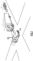
- Figure 1 represents schematically a situation of potential collision between a vehicle 1 and an obstacle 3.
- the vehicle 1 is a truck moving on a straight road (See arrow F1).
- the invention is obviously applicable to any other type of vehicle.
- the obstacle 3 is, for the example, a crossing vehicle (See arrow F3), more precisely a vehicle having passed by a red light at an intersection. More generally, it can be any up front vehicle with an important speed gap with our current vehicle.
- the truck 1 is a semi-autonomous vehicle, meaning that this vehicle cannot be driven without driver on board, but that the vehicle integrates one or more automated functions which, when they are activated (automatically) change the dynamic conditions of the vehicle (speed and/or trajectory).
- the invention is also applicable when the vehicle is fully autonomous, i.e. when the vehicle can be driven without driver on board.
- the truck 1 includes a controller (not represented) capable of activating an automated function, involving strong braking of the vehicle 1.
- said automated function is an advanced emergency braking function that is performed by an Advanced Emergency braking system integrated in the controller.
- the invention is also applicable to any other automated function involving strong braking.
- other systems such as the Adaptive Cruise Control systems, Queue assistance systems, Automotive distance control systems and Stop and go systems may involve strong braking when they are activated.
- advanced emergency braking function is activated to avoid a collision with the vehicle 3 crossing the road in front of the vehicle 1, meaning that strong braking of the truck 1 automatically occurs.
- the method of the invention then includes a first step 100 consisting in, after said automated function is complete, collecting information relative to the space in front of the vehicle 1. More precisely, this consists, as shown in figure 2 , in measuring the distance d to the nearest obstacle 4 in front of the vehicle 1.
- such information can be collected by a radar 10 or any other detection device arranged at the front (longitudinal) end of the vehicle and transmitted to the controller of the truck 1.
- the radar 10 may be replaced by an ultrasonic sensor, a laser sensor, a Lidar sensor, a camera or any sensor being able to give an indication about the distance with an upfront obstacle.
- the distance information can also be collected by any other vehicle to vehicle communication means giving the exact position of each and single vehicle in the surrounding, etc.
- the radar 10 or any comparable measuring means has a measurement field which extends in front of the vehicle, i.e. in the longitudinal direction of the vehicle.
- this measurement field is represented as a detection cone. Accordingly, the measurement field extends across the entire width of the vehicle, meaning that the measuring means is able to detect any obstacle in front of the vehicle 1.
- the radar 10 assesses the presence of obstacle(s) in the measurement field. It is then possible to determine which obstacle is the nearest one from the vehicle and at which distance is this obstacle from the vehicle 1.
- step 102 it is determined, at a step 102 whether the space in front of the vehicle 1 is sufficient to enable the vehicle 1 to move forward. More precisely, it is determined whether the distance d is sufficient to enable the vehicle 1 to reaccelerate.
- step 102 consists in comparing the measured distance d with said threshold value.
- Step 102 is performed by the controller of the truck itself, which preferably includes a processing unit capable of processing the information.
- the method consists, at a step 110, in reaccelerating only if the space in front of the vehicle is sufficient, i.e. only if said distance d is sufficient.
- the condition of having sufficient space in front of the vehicle is necessary for allowing the vehicle to move forward. This means that if the distance d is not sufficient to enable the vehicle 1 to reaccelerate, then there is no automatic reacceleration and the method is ended (Step 108).
- the gap with the upfront vehicle can be closed to a tiny distance like a few dozens of cm (e.g. 30cm).
- the method includes another step 104 prior to step 110, consisting in checking, after said automated function is complete, whether the vehicle is in proper working condition. Then, at step 110, the vehicle 1 is reaccelerated only if the vehicle is in proper working condition.
- an electronic control unit constantly receives measurements from at least one sensor, in particular from at least one accelerometer.
- This sensor is designed for measuring the acceleration (and deceleration) of the vehicle in the forward (longitudinal) direction.
- a collision algorithm integrated in the controller, includes a step of calculating one or more physical criteria. In particular, if the measured deceleration is higher than a specific threshold, then it is determined that the vehicle has been involved in an accident. Accordingly, the step of reacceleration is not computed.
- This kind of algorithm is known as such, as it is already implemented for triggering the activation of the air bags.
- Step 108 when a collision has occurred, it may be determined that the vehicle is no more in proper condition to move forward again. More precisely, when the measured deceleration is higher than said specific threshold, a signal can be sent to the controller for informing the controller of an accident. Accordingly, there is no automatic reacceleration (Step 108). In this specific situation, the driver must regain control to move the vehicle forward again, provided that the vehicle is still in conditions to move. If the truck has collided with the upfront vehicle, we do not execute the automatic reacceleration as it would be hard to monitor the basic vehicle functions availability (Acceleration, breaking, direction, upfront distance calculation means etc).
- the method includes another step 106 prior to step 110, consisting in checking, after said automated function is complete, whether the vehicle is between the lane markers L1 and L2 of the road. Then, at step c), the vehicle is reaccelerated only if the vehicle is still between the lane markers L1 and L2.
- a camera 12 may be mounted in the front (longitudinal) end of the vehicle to detect the lanes L1 and L2 of the road. The images captured by the camera 12 can then be processed to determine if the vehicle is between the lanes L1 and L2 or across the road. Obviously, if after the strong automatic braking, the vehicle 1 comes across the road (as in the configuration of figure 3 ), there is no reacceleration (Step 108).
- Steps 100 to 110 are automated steps, i.e. steps that are executed by the vehicle controller. In other words, these steps are not manually executed by the driver or any other person.
- the vehicle is capable of moving in a platooning mode wherein the vehicle moves with other vehicles within a platoon of vehicles and the method described above is implemented only when the vehicle is in platooning mode.
Landscapes
- Engineering & Computer Science (AREA)
- Transportation (AREA)
- Mechanical Engineering (AREA)
- Chemical & Material Sciences (AREA)
- Combustion & Propulsion (AREA)
- Automation & Control Theory (AREA)
- Physics & Mathematics (AREA)
- General Physics & Mathematics (AREA)
- Human Computer Interaction (AREA)
- Control Of Driving Devices And Active Controlling Of Vehicle (AREA)
- Traffic Control Systems (AREA)
Description
- The present invention concerns a method for controlling a vehicle.
- In the automotive industry, modern vehicles now integrate a plurality of automated systems, such as Advanced Emergency Braking system (AEBS), Adaptive Cruise Control (ACC) system, queue assistance system, Stop and Go system, etc. Each one of these systems is part of a controller of the vehicle, and there is an associated automated function to each system.
- In some situations, an automated function involves strong braking of the vehicle. This is for example the case of the AEBS function, whose purpose is to avoid or mitigate a collision with a front obstacle. Such function results in an automatic application of the brakes at the maximum effort. Strong braking may also occur in the other above-listed automated functions.
- When a strong braking (or emergency braking) occurs, the automated function is usually aborted when the vehicle is at standstill and the driver has to take over to move the vehicle forward again. In practice, the driver circumvents the obstacle or moves forward again if there is no more obstacle. Indeed, when the obstacle is a crossing vehicle/pedestrian/animal, it opposes the passage of the vehicle only for a few seconds. When the obstacle is an upfront vehicle placed on the same lane, that upfront vehicle can sometimes accelerate again. The problem is that, taking into account the reaction time of the driver, the vehicle may rest at standstill on the lane for a few seconds, and there is a risk of collision with the vehicle(s) travelling behind, which may not have sufficient time or distance to slow down.
- The objective of the invention is then to provide a new method for controlling a vehicle, which enables limiting the risk of collision with vehicle(s) travelling behind after a strong automatic braking has occurred.
- With this respect, the invention concerns a method according to
claim 1. -
US 2016/229397 discloses a particular system that is capable of sensing that the vehicle is about to collide with a vehicle approaching from behind and of maneuvering the vehicle to use available space in front of the vehicle to increase the distance with the rear end vehicle. The system is also capable of sensing a collision with a front obstacle and of automatically braking the vehicle to avoid or mitigate such collision. -
DE 10 2006 059915 A1 -
US 2017/106858 discloses a process wherein the preliminary step is to receive an information relative to the driver fatigue. Then, the vehicle speed is automatically increased or decreased, depending on the situation. For example, the vehicle may be automatically accelerated if the distance between the vehicle and another vehicle approaching from behind is inferior to a safety distance. -
US 9 514 647 -
EP 1 703 482 A1 -
DE 10 2011 108870 A1 discloses a method wherein the lane guidance device is automatically activated for autonomous driving of the vehicle in the event of an accident. By activating the lane guidance device, the vehicle is automatically guided within the lane by the lane guidance device. In one version, the lane guidance system of the lane guidance device influences a steering system of the vehicle. -
US 2008/266052 A1 discloses stopping the vehicle during a stop and go automated function. When the vehicle is stopped, it is reaccelerated if no objects are detected within the range of sensors. - The above-mentioned prior art documents teach that, on one side, it is known to automatically decelerate a vehicle to avoid a collision with a front obstacle and that, on the other side, it is known to automatically accelerate a vehicle when the safety distance with a following vehicle is too short. However, none of these prior art documents discloses the possibility of reaccelerating the vehicle just after a strong automatic braking action has occurred.
- The method of the invention achieves reaccelerating automatically the vehicle after an automated function, involving strong braking, has occurred. This and the above objects are addressed with the method of
claim 1. Accordingly, the driver does not have to take over to move the vehicle forward, as it is automatically performed. There is then a gain of time of a few seconds, given that the reacceleration does not depend on the reaction time of the driver. Accordingly, the automatic reacceleration helps increasing the safety distance with the vehicle approaching from behind, and provides the vehicle(s) behind more time and/or distance to slow down. Obviously, the method works only if, after strong braking has occurred, there is sufficient space in front of the vehicle to move forward. The method then involves checking for available room (or space) in front of the vehicle. - Advantageous, but not compulsory features, of the method are defined in the
claims 2 to 7. - The invention will be better understood from reading the following description, given solely by way of several non-limiting examples and with reference to the appended drawings, in which:
-
Figure 1 represents a situation wherein an automated function is performed to apply strong braking; -
Figure 2 represents a view from above after said automated function is complete; -
Figure 3 represents another view from above after said automated function is complete, in a configuration other than that offigure 2 ; -
Figure 4 is a diagram representing the main steps of the method according to the invention. -
Figure 1 represents schematically a situation of potential collision between avehicle 1 and anobstacle 3. In the example, thevehicle 1 is a truck moving on a straight road (See arrow F1). However, the invention is obviously applicable to any other type of vehicle. Also, theobstacle 3 is, for the example, a crossing vehicle (See arrow F3), more precisely a vehicle having passed by a red light at an intersection. More generally, it can be any up front vehicle with an important speed gap with our current vehicle. - There is also another
vehicle 2, approaching thetruck 1 from behind (See arrow F2). - In the example, the
truck 1 is a semi-autonomous vehicle, meaning that this vehicle cannot be driven without driver on board, but that the vehicle integrates one or more automated functions which, when they are activated (automatically) change the dynamic conditions of the vehicle (speed and/or trajectory). Obviously, the invention is also applicable when the vehicle is fully autonomous, i.e. when the vehicle can be driven without driver on board. - Typically, the
truck 1 includes a controller (not represented) capable of activating an automated function, involving strong braking of thevehicle 1. in a preferred embodiment, said automated function is an advanced emergency braking function that is performed by an Advanced Emergency braking system integrated in the controller. However, in alternative embodiments, the invention is also applicable to any other automated function involving strong braking. In particular, other systems, such as the Adaptive Cruise Control systems, Queue assistance systems, Automotive distance control systems and Stop and go systems may involve strong braking when they are activated. - In the situation of
figure 1 , advanced emergency braking function is activated to avoid a collision with thevehicle 3 crossing the road in front of thevehicle 1, meaning that strong braking of thetruck 1 automatically occurs. - With respect to
figure 4 , the method of the invention then includes afirst step 100 consisting in, after said automated function is complete, collecting information relative to the space in front of thevehicle 1. More precisely, this consists, as shown infigure 2 , in measuring the distance d to thenearest obstacle 4 in front of thevehicle 1. - Typically, such information can be collected by a
radar 10 or any other detection device arranged at the front (longitudinal) end of the vehicle and transmitted to the controller of thetruck 1. Alternatively, theradar 10 may be replaced by an ultrasonic sensor, a laser sensor, a Lidar sensor, a camera or any sensor being able to give an indication about the distance with an upfront obstacle. The distance information can also be collected by any other vehicle to vehicle communication means giving the exact position of each and single vehicle in the surrounding, etc. - The
radar 10 or any comparable measuring means, has a measurement field which extends in front of the vehicle, i.e. in the longitudinal direction of the vehicle. Advantageously, in the example, this measurement field is represented as a detection cone. Accordingly, the measurement field extends across the entire width of the vehicle, meaning that the measuring means is able to detect any obstacle in front of thevehicle 1. - The radar 10 (or any comparable measuring means in replacement) assesses the presence of obstacle(s) in the measurement field. It is then possible to determine which obstacle is the nearest one from the vehicle and at which distance is this obstacle from the
vehicle 1. - Then, it is determined, at a
step 102 whether the space in front of thevehicle 1 is sufficient to enable thevehicle 1 to move forward. More precisely, it is determined whether the distance d is sufficient to enable thevehicle 1 to reaccelerate. - In practice, the distance d to the
nearest obstacle 4 in front of thevehicle 1 is considered as being sufficient to enable thevehicle 1 to reaccelerate if such distance d is superior to a threshold value, for example superior to 5 meters. Accordingly,step 102 consists in comparing the measured distance d with said threshold value. - Step 102 is performed by the controller of the truck itself, which preferably includes a processing unit capable of processing the information.
- Afterwards, the method consists, at a
step 110, in reaccelerating only if the space in front of the vehicle is sufficient, i.e. only if said distance d is sufficient. One then understands that the condition of having sufficient space in front of the vehicle is necessary for allowing the vehicle to move forward. This means that if the distance d is not sufficient to enable thevehicle 1 to reaccelerate, then there is no automatic reacceleration and the method is ended (Step 108). - Preferably, when the vehicle has decided to reaccelerate, the gap with the upfront vehicle can be closed to a tiny distance like a few dozens of cm (e.g. 30cm).
- Preferably, the method includes another
step 104 prior to step 110, consisting in checking, after said automated function is complete, whether the vehicle is in proper working condition. Then, atstep 110, thevehicle 1 is reaccelerated only if the vehicle is in proper working condition. - In practice, an electronic control unit (ECU) constantly receives measurements from at least one sensor, in particular from at least one accelerometer. This sensor is designed for measuring the acceleration (and deceleration) of the vehicle in the forward (longitudinal) direction.
- A collision algorithm, integrated in the controller, includes a step of calculating one or more physical criteria. In particular, if the measured deceleration is higher than a specific threshold, then it is determined that the vehicle has been involved in an accident. Accordingly, the step of reacceleration is not computed. This kind of algorithm is known as such, as it is already implemented for triggering the activation of the air bags.
- For example, when a collision has occurred, it may be determined that the vehicle is no more in proper condition to move forward again. More precisely, when the measured deceleration is higher than said specific threshold, a signal can be sent to the controller for informing the controller of an accident. Accordingly, there is no automatic reacceleration (Step 108). In this specific situation, the driver must regain control to move the vehicle forward again, provided that the vehicle is still in conditions to move. If the truck has collided with the upfront vehicle, we do not execute the automatic reacceleration as it would be hard to monitor the basic vehicle functions availability (Acceleration, breaking, direction, upfront distance calculation means etc...).
- Advantageously, and as represented on
figure 3 , the method includes anotherstep 106 prior to step 110, consisting in checking, after said automated function is complete, whether the vehicle is between the lane markers L1 and L2 of the road. Then, at step c), the vehicle is reaccelerated only if the vehicle is still between the lane markers L1 and L2. Typically, and in known manner, acamera 12 may be mounted in the front (longitudinal) end of the vehicle to detect the lanes L1 and L2 of the road. The images captured by thecamera 12 can then be processed to determine if the vehicle is between the lanes L1 and L2 or across the road. Obviously, if after the strong automatic braking, thevehicle 1 comes across the road (as in the configuration offigure 3 ), there is no reacceleration (Step 108). -
Steps 100 to 110 are automated steps, i.e. steps that are executed by the vehicle controller. In other words, these steps are not manually executed by the driver or any other person. - In an alternative embodiment, the vehicle is capable of moving in a platooning mode wherein the vehicle moves with other vehicles within a platoon of vehicles and the method described above is implemented only when the vehicle is in platooning mode.
Claims (7)
- Method for controlling a vehicle (1) moving on a road, the method comprising automated steps performed by a controller of the vehicle and consisting in:a) activating an emergency braking function involving an emergency braking of the vehicle to avoid a collision,b) after said emergency braking is complete, measuring (100) the distance (d) to the nearest obstacle (4) in front of the vehicle (1);c) determining (102) whether said distance (d) is superior to a threshold value; andd) only if said distance is superior to said threshold value, reaccelerating (110) the vehicle.
- Method according to claim 1, further comprising other steps prior to step d) and consisting in:- measuring the deceleration of the vehicle during the period of activation of said emergency braking function, and- comparing the measured deceleration with a specific threshold,and in that, at step d), the vehicle (1) is reaccelerated (110) only if the measured deceleration is below the specific threshold.
- Method according to previous claim, characterized in that the specific threshold is identical to that used for activating air bag(s) of the vehicle.
- Method according to any previous claim, characterized in that, at step d), the vehicle (1) is reaccelerated (110) only if the vehicle (1) is between lane markers (L1, L2) of the road.
- Method according to any previous claim, characterized in that the vehicle (1) is an autonomous vehicle.
- Method according to any previous claim, characterized in that the vehicle (1) is a semi-autonomous vehicle.
- Method according to any previous claim, characterized in that the vehicle (1) is capable of moving in a platooning mode wherein the vehicle (1) moves with other vehicles within a platoon of vehicles, and in that the method is implemented when the vehicle (1) is in platooning mode.
Applications Claiming Priority (1)
| Application Number | Priority Date | Filing Date | Title |
|---|---|---|---|
| PCT/IB2018/000131 WO2019138262A1 (en) | 2018-01-09 | 2018-01-09 | Method for controlling a vehicle |
Publications (3)
| Publication Number | Publication Date |
|---|---|
| EP3737578A1 EP3737578A1 (en) | 2020-11-18 |
| EP3737578C0 EP3737578C0 (en) | 2024-09-18 |
| EP3737578B1 true EP3737578B1 (en) | 2024-09-18 |
Family
ID=61599528
Family Applications (1)
| Application Number | Title | Priority Date | Filing Date |
|---|---|---|---|
| EP18709768.8A Active EP3737578B1 (en) | 2018-01-09 | 2018-01-09 | Method for controlling a vehicle |
Country Status (4)
| Country | Link |
|---|---|
| US (1) | US11912127B2 (en) |
| EP (1) | EP3737578B1 (en) |
| CN (1) | CN111565961A (en) |
| WO (1) | WO2019138262A1 (en) |
Families Citing this family (3)
| Publication number | Priority date | Publication date | Assignee | Title |
|---|---|---|---|---|
| KR102794170B1 (en) * | 2019-11-18 | 2025-04-09 | 현대모비스 주식회사 | Rear cross collision detecting system and method |
| JP7540385B2 (en) * | 2021-04-13 | 2024-08-27 | 株式会社デンソー | Vehicle control device |
| CN115923787B (en) * | 2022-12-20 | 2026-03-20 | 浙江零跑科技股份有限公司 | A cruise control method, device and storage medium |
Citations (1)
| Publication number | Priority date | Publication date | Assignee | Title |
|---|---|---|---|---|
| US20120166058A1 (en) * | 2010-12-28 | 2012-06-28 | GM Global Technology Operations LLC | Method and monitoring device for monitoring a starting maneuver of a motor vehicle |
Family Cites Families (21)
| Publication number | Priority date | Publication date | Assignee | Title |
|---|---|---|---|---|
| DE102005009702A1 (en) | 2005-03-03 | 2006-09-07 | Robert Bosch Gmbh | Distance measuring device and method for functional testing of a distance measurement |
| JP2006259895A (en) * | 2005-03-15 | 2006-09-28 | Omron Corp | Moving body start control device |
| JP2008121583A (en) * | 2006-11-13 | 2008-05-29 | Toyota Motor Corp | Vehicle control device |
| DE102006059915A1 (en) | 2006-12-19 | 2008-07-03 | Adc Automotive Distance Control Systems Gmbh | Motor vehicle e.g. truck, guidance determining method for driver assisting system, involves automatically determining vehicle situation adapted to traffic situation under consideration of determined speed or distance adapted to situation |
| DE102009057836B4 (en) * | 2009-12-10 | 2013-02-21 | Continental Teves Ag & Co. Ohg | Emergency braking assistance system to assist a driver of a vehicle when starting |
| US9514647B2 (en) | 2010-10-20 | 2016-12-06 | GM Global Technology Operations LLC | Optimal acceleration profile for enhanced collision avoidance |
| DE102011108870A1 (en) | 2011-07-28 | 2012-04-12 | Daimler Ag | Method for influencing movement of vehicle i.e. motor car, during accident, involves automatically deactivating track guide device for autonomous operation of vehicle when accident of vehicle is detected |
| DE102011114072C5 (en) * | 2011-09-22 | 2021-04-22 | Knorr-Bremse Systeme für Nutzfahrzeuge GmbH | Driver assistance system with autonomous braking to a standstill |
| WO2015040634A2 (en) * | 2013-09-18 | 2015-03-26 | Muthukumar Prasad | Smart active adaptive autonomous short distance manoeuvring & directional warning system with optimal acceleration for avoiding or mitigating imminent & inevitable side impact and rear end collision |
| US20170001636A1 (en) * | 2015-07-01 | 2017-01-05 | Delphi Technologies, Inc. | Automated Vehicle Response To Imminent Rear-End Collision |
| KR102374735B1 (en) * | 2015-09-14 | 2022-03-15 | 주식회사 만도모빌리티솔루션즈 | Driving assistant apparatus and driving assistant method |
| CN105894734A (en) | 2015-10-19 | 2016-08-24 | 乐卡汽车智能科技(北京)有限公司 | Fatigue driving early warning method and system applied to traffic tool |
| DE102016216745A1 (en) * | 2015-12-18 | 2017-06-22 | Ford Global Technologies, Llc | Method for operating a motor vehicle |
| DE102016203727A1 (en) * | 2016-03-08 | 2017-09-14 | Robert Bosch Gmbh | A method for avoiding a collision between a first vehicle and a second vehicle and control device |
| US9701307B1 (en) * | 2016-04-11 | 2017-07-11 | David E. Newman | Systems and methods for hazard mitigation |
| KR101834351B1 (en) * | 2016-07-14 | 2018-03-05 | 엘지전자 주식회사 | Driving assistance Apparatus for Vehicle |
| FR3054191B1 (en) * | 2016-07-21 | 2019-09-20 | Peugeot Citroen Automobiles Sa | DEVICE FOR SECURING A STOP VEHICLE IN THE PRESENCE OF A RISK OF REAR COLLISION |
| US20180354507A1 (en) * | 2017-06-08 | 2018-12-13 | Continental Automotive Systems, Inc. | Rear collision reduction by torque override |
| JP7049808B2 (en) * | 2017-11-08 | 2022-04-07 | 株式会社デンソー | Braking control device |
| DE102017223480A1 (en) * | 2017-12-20 | 2019-06-27 | Robert Bosch Gmbh | Method and device for automatically controlling the longitudinal dynamics of a vehicle |
| US10467907B2 (en) * | 2017-12-28 | 2019-11-05 | Bendix Commercial Vehicle Systems Llc | Initialization and safety maintenance strategy for platooning vehicles |
-
2018
- 2018-01-09 WO PCT/IB2018/000131 patent/WO2019138262A1/en not_active Ceased
- 2018-01-09 CN CN201880085988.2A patent/CN111565961A/en active Pending
- 2018-01-09 US US16/960,826 patent/US11912127B2/en active Active
- 2018-01-09 EP EP18709768.8A patent/EP3737578B1/en active Active
Patent Citations (1)
| Publication number | Priority date | Publication date | Assignee | Title |
|---|---|---|---|---|
| US20120166058A1 (en) * | 2010-12-28 | 2012-06-28 | GM Global Technology Operations LLC | Method and monitoring device for monitoring a starting maneuver of a motor vehicle |
Also Published As
| Publication number | Publication date |
|---|---|
| US20200361490A1 (en) | 2020-11-19 |
| US11912127B2 (en) | 2024-02-27 |
| EP3737578C0 (en) | 2024-09-18 |
| EP3737578A1 (en) | 2020-11-18 |
| CN111565961A (en) | 2020-08-21 |
| WO2019138262A1 (en) | 2019-07-18 |
Similar Documents
| Publication | Publication Date | Title |
|---|---|---|
| US8457359B2 (en) | Method and assistance system for detecting objects in the surrounding area of a vehicle | |
| EP3196089B1 (en) | Vehicle safety assist system, vehicle comprising a vehicle safety assist system and a method for providing driver warning or performing autonomous braking | |
| US9783169B2 (en) | Method for assisting a driver of a motor vehicle | |
| EP2902291B1 (en) | Method for minimizing automatic braking intrusion based on collision confidence | |
| EP2902290B1 (en) | System for accommodating a pedestrian during autonomous vehicle operation | |
| US8150583B2 (en) | Method and apparatus for avoiding or mitigating vehicle collisions | |
| US6624747B1 (en) | Method for preventing the collision of a vehicle with an obstacle located in front of the vehicle and braking device | |
| EP2878507B1 (en) | Drive assist device | |
| EP2451682B1 (en) | Method for correctly carrying out autonomous emergency braking in a road vehicle | |
| EP3078515A1 (en) | Collision avoidance based on front wheel off tracking during reverse operation | |
| EP3539837B1 (en) | A vehicle radar system for detecting preceding vehicles | |
| KR20160023193A (en) | Method and Apparatus of Predicting Collision Emergency for Omnidirectional Application in Emergency Brake System | |
| US11753013B2 (en) | Method for operating a driving assistance system, and driving assistance system | |
| US10557935B2 (en) | Determining a state of a vehicle and assisting a driver in driving the vehicle | |
| JP5163991B2 (en) | Vehicle speed control method in complex traffic situations | |
| JP2008516851A (en) | How to check related objects | |
| EP3597511B1 (en) | Method and system for providing a steering guidance to a driver of a host vehicle | |
| EP3471077B1 (en) | Automated vehicle safety system that protects pedestrians | |
| US9855946B2 (en) | Method and device for avoiding a collision of a motor vehicle with at least one other object which approaches the motor vehicle in such a way that a collision between the motor vehicle and the approaching object is imminent | |
| US20180043889A1 (en) | Object tracking prior to and during a collision | |
| CN114104003B (en) | Vehicle control method | |
| EP2756992A1 (en) | Motor vehicle safety arrangement and method | |
| EP3737578B1 (en) | Method for controlling a vehicle | |
| US12411231B2 (en) | Vehicle radar system for detecting preceding objects | |
| CN117545673A (en) | Method for operating a vehicle |
Legal Events
| Date | Code | Title | Description |
|---|---|---|---|
| STAA | Information on the status of an ep patent application or granted ep patent |
Free format text: STATUS: UNKNOWN |
|
| STAA | Information on the status of an ep patent application or granted ep patent |
Free format text: STATUS: THE INTERNATIONAL PUBLICATION HAS BEEN MADE |
|
| PUAI | Public reference made under article 153(3) epc to a published international application that has entered the european phase |
Free format text: ORIGINAL CODE: 0009012 |
|
| STAA | Information on the status of an ep patent application or granted ep patent |
Free format text: STATUS: REQUEST FOR EXAMINATION WAS MADE |
|
| 17P | Request for examination filed |
Effective date: 20200703 |
|
| AK | Designated contracting states |
Kind code of ref document: A1 Designated state(s): AL AT BE BG CH CY CZ DE DK EE ES FI FR GB GR HR HU IE IS IT LI LT LU LV MC MK MT NL NO PL PT RO RS SE SI SK SM TR |
|
| AX | Request for extension of the european patent |
Extension state: BA ME |
|
| DAV | Request for validation of the european patent (deleted) | ||
| DAX | Request for extension of the european patent (deleted) | ||
| STAA | Information on the status of an ep patent application or granted ep patent |
Free format text: STATUS: EXAMINATION IS IN PROGRESS |
|
| 17Q | First examination report despatched |
Effective date: 20220802 |
|
| RAP1 | Party data changed (applicant data changed or rights of an application transferred) |
Owner name: VOLVO AUTONOMOUS SOLUTIONS AB |
|
| GRAP | Despatch of communication of intention to grant a patent |
Free format text: ORIGINAL CODE: EPIDOSNIGR1 |
|
| GRAP | Despatch of communication of intention to grant a patent |
Free format text: ORIGINAL CODE: EPIDOSNIGR1 |
|
| STAA | Information on the status of an ep patent application or granted ep patent |
Free format text: STATUS: GRANT OF PATENT IS INTENDED |
|
| INTG | Intention to grant announced |
Effective date: 20240614 |
|
| RAP3 | Party data changed (applicant data changed or rights of an application transferred) |
Owner name: VOLVO AUTONOMOUS SOLUTIONS AB |
|
| GRAS | Grant fee paid |
Free format text: ORIGINAL CODE: EPIDOSNIGR3 |
|
| GRAA | (expected) grant |
Free format text: ORIGINAL CODE: 0009210 |
|
| STAA | Information on the status of an ep patent application or granted ep patent |
Free format text: STATUS: THE PATENT HAS BEEN GRANTED |
|
| AK | Designated contracting states |
Kind code of ref document: B1 Designated state(s): AL AT BE BG CH CY CZ DE DK EE ES FI FR GB GR HR HU IE IS IT LI LT LU LV MC MK MT NL NO PL PT RO RS SE SI SK SM TR |
|
| REG | Reference to a national code |
Ref country code: GB Ref legal event code: FG4D |
|
| REG | Reference to a national code |
Ref country code: CH Ref legal event code: EP |
|
| REG | Reference to a national code |
Ref country code: DE Ref legal event code: R096 Ref document number: 602018074466 Country of ref document: DE |
|
| REG | Reference to a national code |
Ref country code: IE Ref legal event code: FG4D |
|
| U01 | Request for unitary effect filed |
Effective date: 20240924 |
|
| U07 | Unitary effect registered |
Designated state(s): AT BE BG DE DK EE FI FR IT LT LU LV MT NL PT RO SE SI Effective date: 20241017 |
|
| PG25 | Lapsed in a contracting state [announced via postgrant information from national office to epo] |
Ref country code: NO Free format text: LAPSE BECAUSE OF FAILURE TO SUBMIT A TRANSLATION OF THE DESCRIPTION OR TO PAY THE FEE WITHIN THE PRESCRIBED TIME-LIMIT Effective date: 20241218 |
|
| PG25 | Lapsed in a contracting state [announced via postgrant information from national office to epo] |
Ref country code: GR Free format text: LAPSE BECAUSE OF FAILURE TO SUBMIT A TRANSLATION OF THE DESCRIPTION OR TO PAY THE FEE WITHIN THE PRESCRIBED TIME-LIMIT Effective date: 20241219 |
|
| PG25 | Lapsed in a contracting state [announced via postgrant information from national office to epo] |
Ref country code: HR Free format text: LAPSE BECAUSE OF FAILURE TO SUBMIT A TRANSLATION OF THE DESCRIPTION OR TO PAY THE FEE WITHIN THE PRESCRIBED TIME-LIMIT Effective date: 20240918 |
|
| PG25 | Lapsed in a contracting state [announced via postgrant information from national office to epo] |
Ref country code: RS Free format text: LAPSE BECAUSE OF FAILURE TO SUBMIT A TRANSLATION OF THE DESCRIPTION OR TO PAY THE FEE WITHIN THE PRESCRIBED TIME-LIMIT Effective date: 20241218 |
|
| PG25 | Lapsed in a contracting state [announced via postgrant information from national office to epo] |
Ref country code: RS Free format text: LAPSE BECAUSE OF FAILURE TO SUBMIT A TRANSLATION OF THE DESCRIPTION OR TO PAY THE FEE WITHIN THE PRESCRIBED TIME-LIMIT Effective date: 20241218 Ref country code: NO Free format text: LAPSE BECAUSE OF FAILURE TO SUBMIT A TRANSLATION OF THE DESCRIPTION OR TO PAY THE FEE WITHIN THE PRESCRIBED TIME-LIMIT Effective date: 20241218 Ref country code: HR Free format text: LAPSE BECAUSE OF FAILURE TO SUBMIT A TRANSLATION OF THE DESCRIPTION OR TO PAY THE FEE WITHIN THE PRESCRIBED TIME-LIMIT Effective date: 20240918 Ref country code: GR Free format text: LAPSE BECAUSE OF FAILURE TO SUBMIT A TRANSLATION OF THE DESCRIPTION OR TO PAY THE FEE WITHIN THE PRESCRIBED TIME-LIMIT Effective date: 20241219 |
|
| U20 | Renewal fee for the european patent with unitary effect paid |
Year of fee payment: 8 Effective date: 20250127 |
|
| PG25 | Lapsed in a contracting state [announced via postgrant information from national office to epo] |
Ref country code: IS Free format text: LAPSE BECAUSE OF FAILURE TO SUBMIT A TRANSLATION OF THE DESCRIPTION OR TO PAY THE FEE WITHIN THE PRESCRIBED TIME-LIMIT Effective date: 20250118 |
|
| PG25 | Lapsed in a contracting state [announced via postgrant information from national office to epo] |
Ref country code: SM Free format text: LAPSE BECAUSE OF FAILURE TO SUBMIT A TRANSLATION OF THE DESCRIPTION OR TO PAY THE FEE WITHIN THE PRESCRIBED TIME-LIMIT Effective date: 20240918 |
|
| PG25 | Lapsed in a contracting state [announced via postgrant information from national office to epo] |
Ref country code: ES Free format text: LAPSE BECAUSE OF FAILURE TO SUBMIT A TRANSLATION OF THE DESCRIPTION OR TO PAY THE FEE WITHIN THE PRESCRIBED TIME-LIMIT Effective date: 20240918 |
|
| PG25 | Lapsed in a contracting state [announced via postgrant information from national office to epo] |
Ref country code: PL Free format text: LAPSE BECAUSE OF FAILURE TO SUBMIT A TRANSLATION OF THE DESCRIPTION OR TO PAY THE FEE WITHIN THE PRESCRIBED TIME-LIMIT Effective date: 20240918 Ref country code: CZ Free format text: LAPSE BECAUSE OF FAILURE TO SUBMIT A TRANSLATION OF THE DESCRIPTION OR TO PAY THE FEE WITHIN THE PRESCRIBED TIME-LIMIT Effective date: 20240918 |
|
| PG25 | Lapsed in a contracting state [announced via postgrant information from national office to epo] |
Ref country code: SK Free format text: LAPSE BECAUSE OF FAILURE TO SUBMIT A TRANSLATION OF THE DESCRIPTION OR TO PAY THE FEE WITHIN THE PRESCRIBED TIME-LIMIT Effective date: 20240918 |
|
| PLBE | No opposition filed within time limit |
Free format text: ORIGINAL CODE: 0009261 |
|
| STAA | Information on the status of an ep patent application or granted ep patent |
Free format text: STATUS: NO OPPOSITION FILED WITHIN TIME LIMIT |
|
| 26N | No opposition filed |
Effective date: 20250619 |
|
| REG | Reference to a national code |
Ref country code: CH Ref legal event code: PL |
|
| PG25 | Lapsed in a contracting state [announced via postgrant information from national office to epo] |
Ref country code: MC Free format text: LAPSE BECAUSE OF FAILURE TO SUBMIT A TRANSLATION OF THE DESCRIPTION OR TO PAY THE FEE WITHIN THE PRESCRIBED TIME-LIMIT Effective date: 20240918 |
|
| GBPC | Gb: european patent ceased through non-payment of renewal fee |
Effective date: 20250109 |
|
| PG25 | Lapsed in a contracting state [announced via postgrant information from national office to epo] |
Ref country code: GB Free format text: LAPSE BECAUSE OF NON-PAYMENT OF DUE FEES Effective date: 20250109 |
|
| PG25 | Lapsed in a contracting state [announced via postgrant information from national office to epo] |
Ref country code: CH Free format text: LAPSE BECAUSE OF NON-PAYMENT OF DUE FEES Effective date: 20250131 |
|
| PG25 | Lapsed in a contracting state [announced via postgrant information from national office to epo] |
Ref country code: IE Free format text: LAPSE BECAUSE OF NON-PAYMENT OF DUE FEES Effective date: 20250109 |