EP3737342B1 - Sensor system - Google Patents
Sensor system Download PDFInfo
- Publication number
- EP3737342B1 EP3737342B1 EP19785931.7A EP19785931A EP3737342B1 EP 3737342 B1 EP3737342 B1 EP 3737342B1 EP 19785931 A EP19785931 A EP 19785931A EP 3737342 B1 EP3737342 B1 EP 3737342B1
- Authority
- EP
- European Patent Office
- Prior art keywords
- receiver
- wireless data
- power
- transmitter
- wireless
- Prior art date
- Legal status (The legal status is an assumption and is not a legal conclusion. Google has not performed a legal analysis and makes no representation as to the accuracy of the status listed.)
- Active
Links
Images

Classifications
-
- A—HUMAN NECESSITIES
- A61—MEDICAL OR VETERINARY SCIENCE; HYGIENE
- A61F—FILTERS IMPLANTABLE INTO BLOOD VESSELS; PROSTHESES; DEVICES PROVIDING PATENCY TO, OR PREVENTING COLLAPSING OF, TUBULAR STRUCTURES OF THE BODY, e.g. STENTS; ORTHOPAEDIC, NURSING OR CONTRACEPTIVE DEVICES; FOMENTATION; TREATMENT OR PROTECTION OF EYES OR EARS; BANDAGES, DRESSINGS OR ABSORBENT PADS; FIRST-AID KITS
- A61F2/00—Filters implantable into blood vessels; Prostheses, i.e. artificial substitutes or replacements for parts of the body; Appliances for connecting them with the body; Devices providing patency to, or preventing collapsing of, tubular structures of the body, e.g. stents
- A61F2/50—Prostheses not implantable in the body
- A61F2/68—Operating or control means
- A61F2/70—Operating or control means electrical
- A61F2/72—Bioelectric control, e.g. myoelectric
-
- A—HUMAN NECESSITIES
- A61—MEDICAL OR VETERINARY SCIENCE; HYGIENE
- A61B—DIAGNOSIS; SURGERY; IDENTIFICATION
- A61B5/00—Measuring for diagnostic purposes; Identification of persons
- A61B5/0002—Remote monitoring of patients using telemetry, e.g. transmission of vital signals via a communication network
- A61B5/0015—Remote monitoring of patients using telemetry, e.g. transmission of vital signals via a communication network characterised by features of the telemetry system
- A61B5/0017—Remote monitoring of patients using telemetry, e.g. transmission of vital signals via a communication network characterised by features of the telemetry system transmitting optical signals
-
- A—HUMAN NECESSITIES
- A61—MEDICAL OR VETERINARY SCIENCE; HYGIENE
- A61B—DIAGNOSIS; SURGERY; IDENTIFICATION
- A61B5/00—Measuring for diagnostic purposes; Identification of persons
- A61B5/0002—Remote monitoring of patients using telemetry, e.g. transmission of vital signals via a communication network
- A61B5/0031—Implanted circuitry
-
- A—HUMAN NECESSITIES
- A61—MEDICAL OR VETERINARY SCIENCE; HYGIENE
- A61B—DIAGNOSIS; SURGERY; IDENTIFICATION
- A61B5/00—Measuring for diagnostic purposes; Identification of persons
- A61B5/24—Detecting, measuring or recording bioelectric or biomagnetic signals of the body or parts thereof
- A61B5/25—Bioelectric electrodes therefor
- A61B5/279—Bioelectric electrodes therefor specially adapted for particular uses
- A61B5/296—Bioelectric electrodes therefor specially adapted for particular uses for electromyography [EMG]
-
- A—HUMAN NECESSITIES
- A61—MEDICAL OR VETERINARY SCIENCE; HYGIENE
- A61B—DIAGNOSIS; SURGERY; IDENTIFICATION
- A61B5/00—Measuring for diagnostic purposes; Identification of persons
- A61B5/48—Other medical applications
- A61B5/4851—Prosthesis assessment or monitoring
-
- A—HUMAN NECESSITIES
- A61—MEDICAL OR VETERINARY SCIENCE; HYGIENE
- A61B—DIAGNOSIS; SURGERY; IDENTIFICATION
- A61B2560/00—Constructional details of operational features of apparatus; Accessories for medical measuring apparatus
- A61B2560/02—Operational features
- A61B2560/0204—Operational features of power management
- A61B2560/0214—Operational features of power management of power generation or supply
-
- A—HUMAN NECESSITIES
- A61—MEDICAL OR VETERINARY SCIENCE; HYGIENE
- A61B—DIAGNOSIS; SURGERY; IDENTIFICATION
- A61B2560/00—Constructional details of operational features of apparatus; Accessories for medical measuring apparatus
- A61B2560/02—Operational features
- A61B2560/0204—Operational features of power management
- A61B2560/0214—Operational features of power management of power generation or supply
- A61B2560/0219—Operational features of power management of power generation or supply of externally powered implanted units
-
- A—HUMAN NECESSITIES
- A61—MEDICAL OR VETERINARY SCIENCE; HYGIENE
- A61F—FILTERS IMPLANTABLE INTO BLOOD VESSELS; PROSTHESES; DEVICES PROVIDING PATENCY TO, OR PREVENTING COLLAPSING OF, TUBULAR STRUCTURES OF THE BODY, e.g. STENTS; ORTHOPAEDIC, NURSING OR CONTRACEPTIVE DEVICES; FOMENTATION; TREATMENT OR PROTECTION OF EYES OR EARS; BANDAGES, DRESSINGS OR ABSORBENT PADS; FIRST-AID KITS
- A61F2/00—Filters implantable into blood vessels; Prostheses, i.e. artificial substitutes or replacements for parts of the body; Appliances for connecting them with the body; Devices providing patency to, or preventing collapsing of, tubular structures of the body, e.g. stents
- A61F2/50—Prostheses not implantable in the body
- A61F2/68—Operating or control means
- A61F2/70—Operating or control means electrical
- A61F2002/705—Electromagnetic data transfer
Definitions
- This disclosure relates to systems and methods for obtaining biopotential signals from a plurality of electrodes in communication with existing muscles or nerves of a patient. More particularly, but not exclusively, such systems may be used to control external devices, such as a prosthesis.
- US 2011/237921 discloses systems and methods for producing and using electrodes, which may be flexible and/or stretchable, and interconnection structures that can be used both externally and/or implanted within the body
- US 2014/343691 discloses systems and methods for control of external devices, such as a prosthesis, using biopotential signals from electrodes in communication with existing muscles or nerves of a patient.
- the systems and methods disclosed herein may be utilized to control prosthetic devices.
- a prosthetic device may be controlled using existing muscle groups in the residual limb that the user may be able to voluntarily activate. By connecting sensors to these muscles, the patient may be able to control the prosthetic device by activating the remaining muscles.
- the sensors may be connected to amplification and acquisition circuitry and a processor to control movement in a prosthetic device.
- myoelectric prosthesis refers to devices that use biopotential signals or potentials from voluntarily activated muscles to control the movements of a prosthesis.
- biopotential signals may be collected via an electrode, lead, or sensor.
- Leads are structures that contain one or more electrodes or sensors that are individually placed, or placed in conjunction with other leads.
- Biopotential channels are electrical differences recorded between one or more electrodes. Electrodes/leads/sensors may be placed on or near the surface of the muscle or implanted into the muscle.
- a biopotential-signal-receiving device may also be implanted and may connect with an external transceiver via a wireless communication channel.
- systems and methods consistent with the present disclosure may include a wireless multichannel myoelectric implant.
- a wireless multichannel implant may be used to acquire biopotential signals from implanted electrodes. Representations of the acquired biopotential signals may be transmitted wirelessly to a system outside the body configured to receive, processes, and utilize the signals to control a myoelectric prosthesis.
- an array of electrodes may be implanted on a plurality of leads to ensure broad coverage of the muscles in the implant area. Signals from the array of electrodes may be analyzed following implantation and processed to make one or more "virtual pairs" of electrodes, which may be selected for use in controlling a prosthesis.
- the array of electrodes may be utilized in a flexible configuration that allows for selection of one or more "virtual pairs" that best correspond to a desired biopotential signal used to control a prosthesis.
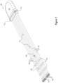
- FIG. 1 illustrates one embodiment of an implantable component 100 of a myoelectric sensor system having a plurality of leads 102 and a plurality of electrodes 104 disposed on each lead consistent with embodiments of the present disclosure.
- the plurality of leads 102 may each connect to a hermetic feedthrough on a housing 114.
- the housing 114 may be formed of a bio-compatible material and may be hermetically sealed to allow for implantation in a patient.
- the housing 114 may be formed of ceramic.
- a plurality of suture holes 112 may be disposed on the housing 114 and may allow the housing to be secured to adjacent tissue.
- the housing 114 may comprise electronics to receive signals from the plurality of electrodes 104 and to communicate with an associated device.
- At least one of the plurality of leads 102 comprises a flexible lead configured to be independently positioned within one or more muscle groups with respect to at least one other of the plurality of leads.
- the leads may be wire, helically wound wire or of other constructions including a biostable polymer comprising a plurality of distinct conductive particles.
- implantable component 100 includes eight full length leads 102, each of which includes four electrodes 104.
- a reference lead 108 may include a plurality of reference electrodes 110.
- a reference electrode 110 may provide a stable electrical potential against which the electrical potential of other electrodes 104 may be amplified and acquired.
- the system may be referred to as a "single-ended" reference.
- the “single-ended” reference may allow for the generation of "virtual pairs" in digital signal processing, rather than using analog amplifiers.
- "virtual pairs" of electrodes may also be generated after acquisition by a comparison the signal from any electrodes 104 to the signal from any other electrode.
- a "virtual pair” may be created by comparison of the signals received by the two electrodes identified by reference number 116.
- a "virtual pair” may be generated as a difference between one of the plurality of electrodes and any other of the plurality of electrodes.
- a “virtual pair” may be generated from multiple signals from electrodes located on one lead or on separate leads. The ability to create a "virtual pair” based on two or more electrode signals provides a wide array of possible combinations. The large number of possible combinations may be analyzed to identify the specific combinations to achieve a specific result (e.g., utilization of a muscle group to control a prosthesis).
- An anchor 106 may be disposed at the end of each lead 102 and reference lead 108.
- the anchors may be configured to hold the leads 102, 108 in place.
- a plurality of flanges 118 may oppose motion in the direction of the housing 114.
- the flanges may be pressed inward and offer little resistance.
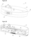
- FIG. 2A illustrates a perspective view of an external transceiver assembly 200 configured to power and communicate with an implantable electronics package consistent with embodiments of the present disclosure.
- external transceiver assembly 200 may be used with implantable component 100 illustrated in Figure 1 .
- the external transceiver assembly may be positioned above the implantable component, and in some embodiments, may be housed within a prosthesis controlled by using biopotential signals received from the implantable component.
- External transceiver assembly 200 may comprise a housing 202 configured to contain electronics for communicating with an implantable component.
- a connector 206 may provide an interface for controlling a prosthesis or other device. Power may also be provided via connector 206 for both the external transceiver assembly 200 and an associated implanted component.
- a plurality of light sources 204 may be disposed on the surface of external transceiver assembly 200. The plurality of light sources 204 may provide information regarding the status of the external transceiver assembly 200 and/or an associated implantable component.
- the external transceiver may include switched or buttons to control operation on the device, including turning off power to the implanted device, changing decode processing parameters such as gain, or switching processing algorithms.
- the plurality of light sources 204 may be used in connection with a corresponding plurality of buttons that may be used to provide input to the external transceiver assembly 200.
- the external transceiver may have a tunable element, such as a trimmable capacitor, to optimize the power transfer efficiency for individual implants or relative placement of the external transceiver and implanted device.
- a tunable element such as a trimmable capacitor
- FIG. 2B illustrates a cross-sectional view of the external transceiver assembly 200 of FIG. 2A taken along line 2B-2B consistent with embodiments of the present disclosure.
- Housing 202 includes a printed circuit board (PCB) 220 to which a plurality of electronics may be mounted.
- the electronics may be configured to enable communication with an implantable component via a receiver 228.
- the receiver may comprise an infrared receiver.
- the electronics may have components to communicate to the implant by means of amplitude modulation of the inductive powering signal.
- Communication from an implantable component may be performed with a receiver 228.
- the receiver 228 may comprise an infrared receiver.
- the infrared frequency range may be well suited to transcutaneous transmission; however, the transceiver may operate using other frequencies in the electromagnetic spectrum.
- a lens 226 may be configured to focus electromagnetic energy received from an implantable component to the receiver 228.
- a lens cover 230 may be disposed at the opening of an aperture in which the lens 226 and receiver 228 are disposed.
- a second electromagnetic shield 234 may be disposed over the receiver to shield the receiver from noise from the power transmitter. In some embodiments, the second electromagnetic shield 234 may be formed of metal.
- An inductive coil 222 may be disposed about a portion of the outer surface of housing 202 nearest to the implantable component.
- the inductive coil 222 may be configured to wirelessly provide electrical power to the implantable component.
- the inductive coil 222 may be inductively coupled with the implantable component to deliver electrical power.
- the wireless electrical power delivered to the implant may be amplitude modulated to provide communication from the external transceiver to the implant.
- a shield 224 may separate the transceiver 226 from the inductive coil 222.
- the shield 224 may be formed of a ferrous material.
- the shield 224 may be formed in a disk shape around an aperture in which the transceiver 228, lens 226, and lens cover 230 are disposed.
- the shield 224 may be formed such that the inductive coil 222 may be received within the shield 224.
- the shield may be a ferrite designed to shape the electromagnetic field to increase the coupling between the external transceiver and the implanted device.
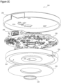
- FIG. 2C illustrates a partially exploded view of the external transceiver assembly of FIG. 2A consistent with embodiments of the present disclosure.
- the bottom portion of housing 202 is omitted to avoid obscuring details of the disclosure.
- the connector 206 and transceiver 228 are disposed on PCB 220.
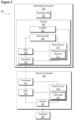
- FIG. 3 illustrates a functional block diagram of an implantable sensor system 300 consistent with embodiments of the present disclosure.
- System 300 includes an electrode array 302, an implantable component 324, an external component 326, and a prosthesis 322 consistent with certain embodiments disclosed herein.
- electrode array 302 and/or housing 328 may be implanted.
- Housing 328 may have features designed to hold implanted structures in place, including but not limited to: screw points, suture holes, anchor points, and special films. Certain features may be reinforced by supplemental materials such as metal rings or polymer fibers to prevent tearing.
- the device may have terminal fixation points that may penetrate intramuscularly and be safely left in the body after explantation.
- Implantable component 324 may have electronics hermetically sealed in a small implantable enclosure.
- implantable component 324 may comprise an amplifier 304, which may be capable of multiple channels of bioamplification.
- Amplifier 304 may exhibit a relatively fast settle time to permit concurrent stimulation and recording with electrodes in close proximity.
- Implantable component 324 may further comprise an A/D converter 306 that is configured to convert the biopotential signals received from amplifier 304 to digital signals.
- a microcontroller unit (MCU) 308 may perform signal processing operations and/or implement other functions.
- MCU 308 may comprise a microcontroller, microprocessor, programmable logic device, or any system used to perform signal processing and perform other functions described herein. Additional signal processing capabilities may be performed by external component 326. As illustrated in Figure 3 , external component 326 may also contain an MCU 316. Still further, additional processing may, according to some embodiments, be implemented using an external device 334 (e.g., a computer, a PDA, a tablet, a phone, or a remote control) connected via wireless communication interface 332. In one embodiment the wireless communication interface 332 may be embodied as a Bluetooth chipset.
- Implantable component 324 may comprise an enclosure made of ceramic, metal, epoxy, polymeric material, or any combination thereof. Hermetic enclosures provide gas-tight areas that are created by metal, glass and ceramic enclosures, or epoxy. Implantable component 324 may include a hermetic enclosure to encapsulate portions of the implant components. Additional surgical materials, such as films, screws, etc., may be implanted to improve the tolerance, biocompatibility, or fixture of implantable component and/or health of skin or other tissues over or near implantable component 324. The device may include features such as tapers or edges to facilitate easier tunneling through tissue during surgical placement. Implantable component 324 may include non-stick or non-adhesive coatings on surfaces to make explantation easier.
- electrode array 302 may be configured to extract biopotential signals from extramuscular and/or intramuscular sites. Electrode array 302 may, for example, be placed in the chest and/or shoulders, arms, hands, pelvic muscle, legs (upper and lower), or any other extramuscular or intramuscular site that may be used along with muscle decoding algorithms for control of prosthetic devices, computers, wheelchairs, robotic exoskeleton, and/or any other internal or external device.
- a power source 310 may be located internally or externally to implantable component 324.
- Power source 310 may be embodied as an inductive device (i.e., an inductive coil for receiving power), such as wireless power receiver 311 or any other suitable system used for providing power to implantable component 324, or in some embodiments may include a battery and battery charging circuitry.
- power may be provided inductively by the wireless power transmitter 319 in external component 326.
- Transceiver 312 may communicate using a variety of technologies.
- transceiver 314 may transmit signals by infrared transmission, reflected impedance transmission, amplitude modulation, and/or any applicable data transmission system. According to some embodiments, transmitted or received data may be recorded.
- External component 326 may be in communication with prosthesis 322 via an interface 320. Signals received from electrode array 302 may be transmitted to prosthesis 322 to induce a desired action or movement. In some embodiments, external component 326 may be configured to be received within or integrated with prosthesis 322.
- a power source 318 may comprise a wireless power transmitter 319 configured to transfer power to a wireless power receiver 311 associated with power source 310.
- wireless power transmitter 319 may be embodied as an inductive coil 222, as illustrated in Figure 2B .
- power source 318 may receive power from prosthesis 322 via interface 320.
- FIG 4 illustrates an exemplary flow chart of a method 400 for controlling a prosthetic device using a system consistent with embodiments disclosed herein.
- an electrode array may be implanted.
- the electrode array be comprised by the implantable component 100 illustrated in Figure 1 .
- the electrode array may be configured in a variety of ways (e.g., in a grid configuration).
- one or more "virtual pairs" in the electrode array corresponding with a biopotential signal may be identified.
- the processing of signals from various electrodes may analyze inputs from a plurality of electrodes in the electrode array and identify one or more "virtual pairs" with desirable characteristics (e.g., a high signal-to-noise ratio).
- desirable characteristics e.g., a high signal-to-noise ratio
- an array comprising a plurality of electrodes may be implanted and later analyzed to identify the electrode signals or composite signals from two or more signals that are best situated for a particular task (e.g., use of a muscle group on a residual limb for control of a prosthesis).
- a plurality of biopotential signals may be associated with a plurality of voluntary motions, and the biopotential signals may be detected using multiple "virtual pairs".
- a first signal associated with a grasping motion may be detected using a first "virtual pair" in the electrode array
- a second signal associated with a pointing motion may be detected using a second "virtual pair”.
- the actions at 402-406 may be associated with a commissioning or training, while the actions at 408-412 may be associated with use of the device. Such training or commissioning may allow for a plurality of motions to be associated with a plurality of biopotential signals.
Landscapes
- Health & Medical Sciences (AREA)
- Life Sciences & Earth Sciences (AREA)
- Engineering & Computer Science (AREA)
- Animal Behavior & Ethology (AREA)
- Veterinary Medicine (AREA)
- Public Health (AREA)
- General Health & Medical Sciences (AREA)
- Biomedical Technology (AREA)
- Heart & Thoracic Surgery (AREA)
- Biophysics (AREA)
- Molecular Biology (AREA)
- Surgery (AREA)
- Medical Informatics (AREA)
- Pathology (AREA)
- Physics & Mathematics (AREA)
- Computer Networks & Wireless Communication (AREA)
- Transplantation (AREA)
- Cardiology (AREA)
- Oral & Maxillofacial Surgery (AREA)
- Vascular Medicine (AREA)
- Prostheses (AREA)
- Measurement Of Length, Angles, Or The Like Using Electric Or Magnetic Means (AREA)
Description
- This disclosure relates to systems and methods for obtaining biopotential signals from a plurality of electrodes in communication with existing muscles or nerves of a patient. More particularly, but not exclusively, such systems may be used to control external devices, such as a prosthesis.
-
US 2011/237921 discloses systems and methods for producing and using electrodes, which may be flexible and/or stretchable, and interconnection structures that can be used both externally and/or implanted within the body -
US 2014/343691 discloses systems and methods for control of external devices, such as a prosthesis, using biopotential signals from electrodes in communication with existing muscles or nerves of a patient. - The invention is set out in the appended set of claims.
-
-
FIG. 1 illustrates one embodiment of an implantable component of a myoelectric sensor system having a plurality of leads and a plurality of electrodes disposed on each lead consistent with embodiments of the present disclosure. -
FIG. 2A illustrates a perspective view of an external transceiver assembly configured to power and communicate with an implantable electrode consistent with embodiments of the present disclosure. -
FIG. 2B illustrates a cross-sectional view of the external transceiver assembly ofFIG. 2A taken along line 2B-2B consistent with embodiments of the present disclosure. -
FIG. 2C illustrates a partially exploded view of the transceiver ofFIG. 2A consistent with embodiments of the present disclosure. -
FIG. 3 illustrates a functional block diagram of an implantable sensor system consistent with embodiments of the present disclosure. -
FIG. 4 illustrates a flow chart of a method of using an implantable myoelectric sensor system consistent with the present disclosure. - Disclosed herein are systems and methods for an implantable myoelectric sensor system that may be utilized in a variety of applications. In some embodiments consistent with the present disclosure, the systems and methods disclosed herein may be utilized to control prosthetic devices. A prosthetic device may be controlled using existing muscle groups in the residual limb that the user may be able to voluntarily activate. By connecting sensors to these muscles, the patient may be able to control the prosthetic device by activating the remaining muscles. The sensors may be connected to amplification and acquisition circuitry and a processor to control movement in a prosthetic device. As used in the present disclosure, the term myoelectric prosthesis refers to devices that use biopotential signals or potentials from voluntarily activated muscles to control the movements of a prosthesis.
- In connection with a myoelectric prosthesis, biopotential signals may be collected via an electrode, lead, or sensor. Leads are structures that contain one or more electrodes or sensors that are individually placed, or placed in conjunction with other leads. Biopotential channels are electrical differences recorded between one or more electrodes. Electrodes/leads/sensors may be placed on or near the surface of the muscle or implanted into the muscle. A biopotential-signal-receiving device may also be implanted and may connect with an external transceiver via a wireless communication channel.
- According to various embodiments, systems and methods consistent with the present disclosure may include a wireless multichannel myoelectric implant. In some embodiments, a wireless multichannel implant may be used to acquire biopotential signals from implanted electrodes. Representations of the acquired biopotential signals may be transmitted wirelessly to a system outside the body configured to receive, processes, and utilize the signals to control a myoelectric prosthesis.
- It may be difficult during a surgery to implant an electrode to determine whether the electrode receives a specific biopotential signal. Accordingly, in various embodiments consistent with the present disclosure, an array of electrodes may be implanted on a plurality of leads to ensure broad coverage of the muscles in the implant area. Signals from the array of electrodes may be analyzed following implantation and processed to make one or more "virtual pairs" of electrodes, which may be selected for use in controlling a prosthesis. In other words, the array of electrodes may be utilized in a flexible configuration that allows for selection of one or more "virtual pairs" that best correspond to a desired biopotential signal used to control a prosthesis.
- The embodiments of the disclosure will be best understood by reference to the drawings, wherein like parts may be designated by like numerals. The components of the disclosed embodiments, as generally described and illustrated in the figures herein, could be arranged and designed in a wide variety of different configurations. Thus, the following detailed description of the embodiments of the systems and methods of the disclosure is not intended to limit the scope of the disclosure, as claimed, but is merely representative of possible embodiments of the disclosure. In addition, the steps of a method do not necessarily need to be executed in any specific order, or even sequentially, nor need the steps be executed only once, unless otherwise specified.
-
FIG. 1 illustrates one embodiment of animplantable component 100 of a myoelectric sensor system having a plurality ofleads 102 and a plurality ofelectrodes 104 disposed on each lead consistent with embodiments of the present disclosure. The plurality ofleads 102 may each connect to a hermetic feedthrough on ahousing 114. In various embodiments, thehousing 114 may be formed of a bio-compatible material and may be hermetically sealed to allow for implantation in a patient. In one specific embodiment, thehousing 114 may be formed of ceramic. A plurality ofsuture holes 112 may be disposed on thehousing 114 and may allow the housing to be secured to adjacent tissue. As discussed in greater detail below, thehousing 114 may comprise electronics to receive signals from the plurality ofelectrodes 104 and to communicate with an associated device. - At least one of the plurality of
leads 102 comprises a flexible lead configured to be independently positioned within one or more muscle groups with respect to at least one other of the plurality of leads. The leads may be wire, helically wound wire or of other constructions including a biostable polymer comprising a plurality of distinct conductive particles. In the illustrated embodiment,implantable component 100 includes eight full length leads 102, each of which includes fourelectrodes 104. - A
reference lead 108 may include a plurality ofreference electrodes 110. Areference electrode 110 may provide a stable electrical potential against which the electrical potential ofother electrodes 104 may be amplified and acquired. The system may be referred to as a "single-ended" reference. The "single-ended" reference may allow for the generation of "virtual pairs" in digital signal processing, rather than using analog amplifiers. - In additional to creating differential pairs between
reference electrodes 110 andelectrodes 104, "virtual pairs" of electrodes may also be generated after acquisition by a comparison the signal from anyelectrodes 104 to the signal from any other electrode. For example, a "virtual pair" may be created by comparison of the signals received by the two electrodes identified byreference number 116. In other words, a "virtual pair" may be generated as a difference between one of the plurality of electrodes and any other of the plurality of electrodes. A "virtual pair" may be generated from multiple signals from electrodes located on one lead or on separate leads. The ability to create a "virtual pair" based on two or more electrode signals provides a wide array of possible combinations. The large number of possible combinations may be analyzed to identify the specific combinations to achieve a specific result (e.g., utilization of a muscle group to control a prosthesis). - An
anchor 106 may be disposed at the end of eachlead 102 andreference lead 108. The anchors may be configured to hold theleads flanges 118 may oppose motion in the direction of thehousing 114. In contrast, when the leads 102, 108 are inserted, the flanges may be pressed inward and offer little resistance. -
FIG. 2A illustrates a perspective view of anexternal transceiver assembly 200 configured to power and communicate with an implantable electronics package consistent with embodiments of the present disclosure. In various embodiments,external transceiver assembly 200 may be used withimplantable component 100 illustrated inFigure 1 . The external transceiver assembly may be positioned above the implantable component, and in some embodiments, may be housed within a prosthesis controlled by using biopotential signals received from the implantable component. -
External transceiver assembly 200 may comprise ahousing 202 configured to contain electronics for communicating with an implantable component. Aconnector 206 may provide an interface for controlling a prosthesis or other device. Power may also be provided viaconnector 206 for both theexternal transceiver assembly 200 and an associated implanted component. A plurality oflight sources 204 may be disposed on the surface ofexternal transceiver assembly 200. The plurality oflight sources 204 may provide information regarding the status of theexternal transceiver assembly 200 and/or an associated implantable component. In some embodiments, the external transceiver may include switched or buttons to control operation on the device, including turning off power to the implanted device, changing decode processing parameters such as gain, or switching processing algorithms. In some embodiments, the plurality oflight sources 204 may be used in connection with a corresponding plurality of buttons that may be used to provide input to theexternal transceiver assembly 200. - The external transceiver may have a tunable element, such as a trimmable capacitor, to optimize the power transfer efficiency for individual implants or relative placement of the external transceiver and implanted device.
-
FIG. 2B illustrates a cross-sectional view of theexternal transceiver assembly 200 ofFIG. 2A taken along line 2B-2B consistent with embodiments of the present disclosure.Housing 202 includes a printed circuit board (PCB) 220 to which a plurality of electronics may be mounted. The electronics may be configured to enable communication with an implantable component via areceiver 228. In some embodiments, the receiver may comprise an infrared receiver. The electronics may have components to communicate to the implant by means of amplitude modulation of the inductive powering signal. - Communication from an implantable component may be performed with a
receiver 228. In some embodiments, thereceiver 228 may comprise an infrared receiver. The infrared frequency range may be well suited to transcutaneous transmission; however, the transceiver may operate using other frequencies in the electromagnetic spectrum. Alens 226 may be configured to focus electromagnetic energy received from an implantable component to thereceiver 228. A lens cover 230 may be disposed at the opening of an aperture in which thelens 226 andreceiver 228 are disposed. A secondelectromagnetic shield 234 may be disposed over the receiver to shield the receiver from noise from the power transmitter. In some embodiments, the secondelectromagnetic shield 234 may be formed of metal. - An
inductive coil 222 may be disposed about a portion of the outer surface ofhousing 202 nearest to the implantable component. Theinductive coil 222 may be configured to wirelessly provide electrical power to the implantable component. Theinductive coil 222 may be inductively coupled with the implantable component to deliver electrical power. In some embodiments, the wireless electrical power delivered to the implant may be amplitude modulated to provide communication from the external transceiver to the implant. - A
shield 224 may separate thetransceiver 226 from theinductive coil 222. In some embodiments, theshield 224 may be formed of a ferrous material. Theshield 224 may be formed in a disk shape around an aperture in which thetransceiver 228,lens 226, and lens cover 230 are disposed. In some embodiments, theshield 224 may be formed such that theinductive coil 222 may be received within theshield 224. The shield may be a ferrite designed to shape the electromagnetic field to increase the coupling between the external transceiver and the implanted device. -
FIG. 2C illustrates a partially exploded view of the external transceiver assembly ofFIG. 2A consistent with embodiments of the present disclosure. The bottom portion ofhousing 202 is omitted to avoid obscuring details of the disclosure. Theconnector 206 andtransceiver 228 are disposed onPCB 220. -
Shield 224 is formed in a disk shape with anaperture 232 in the center. Theaperture 232 may receive thelens 226. Thelens cover 228 may closeaperture 232 in the lower portion of the housing. Achannel 234 is formed around the lower perimeter of theshield 224. Thecoil 222 may be received within theshield 224. -
FIG. 3 illustrates a functional block diagram of animplantable sensor system 300 consistent with embodiments of the present disclosure.System 300 includes anelectrode array 302, animplantable component 324, an external component 326, and aprosthesis 322 consistent with certain embodiments disclosed herein. According to various embodiments,electrode array 302 and/or housing 328 may be implanted. Housing 328 may have features designed to hold implanted structures in place, including but not limited to: screw points, suture holes, anchor points, and special films. Certain features may be reinforced by supplemental materials such as metal rings or polymer fibers to prevent tearing. The device may have terminal fixation points that may penetrate intramuscularly and be safely left in the body after explantation. -
Implantable component 324, for example, may have electronics hermetically sealed in a small implantable enclosure. According to various embodiments,implantable component 324 may comprise anamplifier 304, which may be capable of multiple channels of bioamplification.Amplifier 304 may exhibit a relatively fast settle time to permit concurrent stimulation and recording with electrodes in close proximity. -
Implantable component 324 may further comprise an A/D converter 306 that is configured to convert the biopotential signals received fromamplifier 304 to digital signals. - A microcontroller unit (MCU) 308 may perform signal processing operations and/or implement other functions.
MCU 308 may comprise a microcontroller, microprocessor, programmable logic device, or any system used to perform signal processing and perform other functions described herein. Additional signal processing capabilities may be performed by external component 326. As illustrated inFigure 3 , external component 326 may also contain an MCU 316. Still further, additional processing may, according to some embodiments, be implemented using an external device 334 (e.g., a computer, a PDA, a tablet, a phone, or a remote control) connected via wireless communication interface 332. In one embodiment the wireless communication interface 332 may be embodied as a Bluetooth chipset. -
Implantable component 324 may comprise an enclosure made of ceramic, metal, epoxy, polymeric material, or any combination thereof. Hermetic enclosures provide gas-tight areas that are created by metal, glass and ceramic enclosures, or epoxy.Implantable component 324 may include a hermetic enclosure to encapsulate portions of the implant components. Additional surgical materials, such as films, screws, etc., may be implanted to improve the tolerance, biocompatibility, or fixture of implantable component and/or health of skin or other tissues over or nearimplantable component 324. The device may include features such as tapers or edges to facilitate easier tunneling through tissue during surgical placement.Implantable component 324 may include non-stick or non-adhesive coatings on surfaces to make explantation easier. - In certain embodiments,
electrode array 302 may be configured to extract biopotential signals from extramuscular and/or intramuscular sites.Electrode array 302 may, for example, be placed in the chest and/or shoulders, arms, hands, pelvic muscle, legs (upper and lower), or any other extramuscular or intramuscular site that may be used along with muscle decoding algorithms for control of prosthetic devices, computers, wheelchairs, robotic exoskeleton, and/or any other internal or external device. - A
power source 310 may be located internally or externally toimplantable component 324.Power source 310 may be embodied as an inductive device (i.e., an inductive coil for receiving power), such as wireless power receiver 311 or any other suitable system used for providing power toimplantable component 324, or in some embodiments may include a battery and battery charging circuitry. In the illustrated embodiment, power may be provided inductively by the wireless power transmitter 319 in external component 326. -
Transceiver 312 may communicate using a variety of technologies. In one embodiment,transceiver 314 may transmit signals by infrared transmission, reflected impedance transmission, amplitude modulation, and/or any applicable data transmission system. According to some embodiments, transmitted or received data may be recorded. - External component 326 may be in communication with
prosthesis 322 via aninterface 320. Signals received fromelectrode array 302 may be transmitted toprosthesis 322 to induce a desired action or movement. In some embodiments, external component 326 may be configured to be received within or integrated withprosthesis 322. - A power source 318 may comprise a wireless power transmitter 319 configured to transfer power to a wireless power receiver 311 associated with
power source 310. In one specific embodiment, wireless power transmitter 319 may be embodied as aninductive coil 222, as illustrated inFigure 2B . In some embodiments, power source 318 may receive power fromprosthesis 322 viainterface 320. -
Figure 4 illustrates an exemplary flow chart of amethod 400 for controlling a prosthetic device using a system consistent with embodiments disclosed herein. At 402, an electrode array may be implanted. In one specific embodiment, the electrode array be comprised by theimplantable component 100 illustrated inFigure 1 . In other embodiments, the electrode array may be configured in a variety of ways (e.g., in a grid configuration). - At 404, one or more "virtual pairs" in the electrode array corresponding with a biopotential signal may be identified. In various embodiments the processing of signals from various electrodes may analyze inputs from a plurality of electrodes in the electrode array and identify one or more "virtual pairs" with desirable characteristics (e.g., a high signal-to-noise ratio). As noted above, it may be difficult to place electrodes within living tissue and to acquire desired biopotential signals (i.e., the nerve impulses that cause muscle voluntary muscle contraction or the muscle activity itself). Accordingly, in various embodiments consistent with the present disclosure, an array comprising a plurality of electrodes may be implanted and later analyzed to identify the electrode signals or composite signals from two or more signals that are best situated for a particular task (e.g., use of a muscle group on a residual limb for control of a prosthesis).
- At 406, an identified biopotential signal may be associated via signal processing with a voluntary motion. In some embodiments, a signal "virtual pair" signal may be associated with one or more actions. For example, an identified signal may be associated with a motion to grasp an object with a prosthetic hand. The motion of grasping an object may include a plurality of motions associated with each finger, in addition to positioning the thumb. In some embodiments, all the associated motions may be triggered.
- A plurality of biopotential signals may be associated with a plurality of voluntary motions, and the biopotential signals may be detected using multiple "virtual pairs". In one example, a first signal associated with a grasping motion may be detected using a first "virtual pair" in the electrode array, and a second signal associated with a pointing motion may be detected using a second "virtual pair". In some embodiments, the actions at 402-406 may be associated with a commissioning or training, while the actions at 408-412 may be associated with use of the device. Such training or commissioning may allow for a plurality of motions to be associated with a plurality of biopotential signals.
- Many changes may be made to the details of the above-described embodiments without departing from the underlying principles of the invention. The scope of the present invention should, therefore, be determined only by the following claims.
Claims (14)
- A sensor system, comprising:an implantable component (100, 324), comprising:an electrode array (302) disposed on a plurality of leads (102), each lead comprising a plurality of electrodes (104) coupled to the implantable component and configured to receive a plurality of biopotential signals;a housing (114, 324), comprisinga power source (310) comprising a wireless power receiver configured to wirelessly receive electrical power;an analog to digital converter (306) configured to generate a plurality of digital representations of the biopotential signals;a wireless data transmitter (312) configured to transmit the plurality of digital representations of the biopotential signals; andan external component (326), comprising:a wireless data receiver (314) configured to receive the plurality of digital representations of the biopotential signals;a power source (318) comprising a wireless power transmitter configured to wirelessly transmit electrical power to the implantable component;a shielding component (224) configured to shield the wireless data receiver from the wireless power transmitter; andan interface (320) configured to communicate with a prosthesis and configured to cause the prosthesis to implement a voluntary motion based on the plurality of digital representations of the biopotential signals,wherein at least one of the plurality of leads comprises a flexible lead configured to be independently positioned within a muscle group with respect to at least one other of the plurality of leads.
- The system of claim 1, wherein the wireless data transmitter comprises an infrared transmitter and the wireless data receiver comprises an infrared receiver.
- The system of claim 1, wherein the wireless power transmitter and the wireless power receiver are configured to transfer power using inductive coupling.
- The system of claim 3, wherein the shielding component comprises an aperture and the wireless data receiver is disposed in the aperture.
- The system of claim 1 or claim 2, wherein the external component further comprises a lens disposed between the wireless data receiver and the wireless data transmitter and configured to focus a signal transmitted by the wireless data transmitter on the wireless data receiver.
- The system of claim 5, wherein the shielding component comprises a recess configured to receive the wireless power transmitter.
- The system of any one of the preceding claims, wherein the external component is configured to receive power from the prosthesis.
- The system of any one of the preceding claims, wherein each of the plurality of biopotential signals comprise a representation of a difference between a reference electrode in the electrode array and any other electrode in the electrode array.
- The system of any one of the preceding claims, wherein two of the plurality of biopotential signals from two electrodes in the electrode array are combined to generate a virtual pair.
- The system of any one of the preceding claims, wherein the housing is hermetically sealed.
- The system of any one of the preceding claims, wherein the housing comprises a plurality of anchor points configured to anchor the housing to adjacent tissue.
- The system of any one of the preceding claims, wherein the plurality of biopotential signals comprise myoelectric signals.
- The system of any one of the preceding claims, further comprising a second electromagnetic shield disposed over the receiver to shield the receiver from noise from the power transmitter.
- The system of any one of the preceding claims, wherein the wireless power transmitter comprises a tunable element configured to adjust a power transfer efficiency.
Applications Claiming Priority (2)
| Application Number | Priority Date | Filing Date | Title |
|---|---|---|---|
| US15/870,362 US10729564B2 (en) | 2018-01-12 | 2018-01-12 | Sensor system |
| PCT/US2019/013157 WO2019199364A1 (en) | 2018-01-12 | 2019-01-11 | Sensor system |
Publications (4)
| Publication Number | Publication Date |
|---|---|
| EP3737342A1 EP3737342A1 (en) | 2020-11-18 |
| EP3737342A4 EP3737342A4 (en) | 2021-03-10 |
| EP3737342B1 true EP3737342B1 (en) | 2023-06-07 |
| EP3737342C0 EP3737342C0 (en) | 2023-06-07 |
Family
ID=67213415
Family Applications (1)
| Application Number | Title | Priority Date | Filing Date |
|---|---|---|---|
| EP19785931.7A Active EP3737342B1 (en) | 2018-01-12 | 2019-01-11 | Sensor system |
Country Status (3)
| Country | Link |
|---|---|
| US (2) | US10729564B2 (en) |
| EP (1) | EP3737342B1 (en) |
| WO (1) | WO2019199364A1 (en) |
Families Citing this family (15)
| Publication number | Priority date | Publication date | Assignee | Title |
|---|---|---|---|---|
| US12554325B2 (en) | 2016-07-25 | 2026-02-17 | Meta Platforms Technologies, Llc | Methods and apparatuses for low latency body state prediction based on neuromuscular data |
| EP3697297A4 (en) | 2017-10-19 | 2020-12-16 | Facebook Technologies, Inc. | SYSTEMS AND METHODS FOR IDENTIFYING BIOLOGICAL STRUCTURES ASSOCIATED WITH NEUROMUSCULAR SOURCE SIGNALS |
| US10729564B2 (en) | 2018-01-12 | 2020-08-04 | Ripple Llc | Sensor system |
| US11481030B2 (en) | 2019-03-29 | 2022-10-25 | Meta Platforms Technologies, Llc | Methods and apparatus for gesture detection and classification |
| US11907423B2 (en) | 2019-11-25 | 2024-02-20 | Meta Platforms Technologies, Llc | Systems and methods for contextualized interactions with an environment |
| US11493993B2 (en) | 2019-09-04 | 2022-11-08 | Meta Platforms Technologies, Llc | Systems, methods, and interfaces for performing inputs based on neuromuscular control |
| US12579768B2 (en) | 2018-01-25 | 2026-03-17 | Meta Platforms Technologies, Llc | Wearable electronic devices, extended reality systems including neuromuscular sensors, and methods for generating text from speech input and modifying the generated text based on neuromuscular data |
| US11961494B1 (en) | 2019-03-29 | 2024-04-16 | Meta Platforms Technologies, Llc | Electromagnetic interference reduction in extended reality environments |
| US11150730B1 (en) * | 2019-04-30 | 2021-10-19 | Facebook Technologies, Llc | Devices, systems, and methods for controlling computing devices via neuromuscular signals of users |
| EP3853698A4 (en) | 2018-09-20 | 2021-11-17 | Facebook Technologies, LLC | NEUROMUSCULAR TEXT, WRITING AND DRAWING ENTRY IN AUGMENTED REALITY SYSTEMS |
| CN113423341B (en) * | 2018-11-27 | 2024-12-03 | 元平台技术有限公司 | Method and apparatus for automatic calibration of wearable electrode sensor systems |
| WO2020160290A1 (en) * | 2019-01-31 | 2020-08-06 | Mobile Tech, Inc. | Methods and apparatuses for wireless and non-conductive power and data transfers with electronic devices |
| FR3100440B1 (en) * | 2019-09-09 | 2024-05-31 | Naox Tech | Device for determining the electrical potential of the brain |
| AU2023413106A1 (en) * | 2022-12-22 | 2025-07-03 | Phantom Neuro Inc. | Methods and systems for prosthesis control |
| CN116159244B (en) * | 2023-03-17 | 2024-02-20 | 上海杉翎医疗科技有限公司 | Injection type miniature nerve stimulator and nerve stimulation system |
Family Cites Families (85)
| Publication number | Priority date | Publication date | Assignee | Title |
|---|---|---|---|---|
| US4566464A (en) | 1981-07-27 | 1986-01-28 | Piccone Vincent A | Implantable epilepsy monitor apparatus |
| US4735208B1 (en) | 1987-01-09 | 1995-07-04 | Ad Tech Medical Instr Corp | Subdural strip electrode for determining epileptogenic foci |
| US4850359A (en) | 1987-10-16 | 1989-07-25 | Ad-Tech Medical Instrument Corporation | Electrical brain-contact devices |
| US4903702A (en) | 1988-10-17 | 1990-02-27 | Ad-Tech Medical Instrument Corporation | Brain-contact for sensing epileptogenic foci with improved accuracy |
| US5097835A (en) | 1990-04-09 | 1992-03-24 | Ad-Tech Medical Instrument Corporation | Subdural electrode with improved lead connection |
| US5456254A (en) | 1991-02-15 | 1995-10-10 | Cardiac Pathways Corp | Flexible strip assembly having insulating layer with conductive pads exposed through insulating layer and device utilizing the same |
| AU652494B2 (en) | 1991-11-15 | 1994-08-25 | Minnesota Mining And Manufacturing Company | Solid state conductive polymer compositions, biomedical electrodes containing such compositions, and method of preparing same |
| US5279305A (en) | 1992-08-06 | 1994-01-18 | Pedifutures, Inc. | Electroencephalograph incorporating at least one wireless link |
| US5400782A (en) | 1992-10-07 | 1995-03-28 | Graphic Controls Corporation | Integral medical electrode including a fusible conductive substrate |
| SE502620C2 (en) | 1993-02-26 | 1995-11-27 | Leif Nilsson | urinary catheter |
| US5433742A (en) | 1993-11-19 | 1995-07-18 | Willis; Allan | Conductive adhesive band for cathether electrode |
| US5895369A (en) | 1994-09-30 | 1999-04-20 | Becton Dickinson And Company | Iontophoresis patch/controller interconnection using a conductive elastomer to provide noise-free electrical contact between patch and controller |
| US5681514A (en) | 1995-06-07 | 1997-10-28 | Sulzer Intermedics Inc. | Method for making an implantable conductive lead for use with a cardiac stimulator |
| US6480743B1 (en) | 2000-04-05 | 2002-11-12 | Neuropace, Inc. | System and method for adaptive brain stimulation |
| US6095148A (en) | 1995-11-03 | 2000-08-01 | Children's Medical Center Corporation | Neuronal stimulation using electrically conducting polymers |
| US5868136A (en) | 1996-02-20 | 1999-02-09 | Axelgaard Manufacturing Co. Ltd. | Medical electrode |
| US5924983A (en) | 1996-04-29 | 1999-07-20 | Minnesota Mining And Manufacturing Company | Electrical conductor for biomedical electrodes and biomedical electrodes prepared therefrom |
| US5904712A (en) | 1997-06-12 | 1999-05-18 | Axelgaard Manufacturing Co., Ltd. | Current-controlling electrode |
| US5843155A (en) | 1997-06-12 | 1998-12-01 | Axelgaard Manufacturing Company, Ltd. | Current-controlling electrode system |
| US6024702A (en) | 1997-09-03 | 2000-02-15 | Pmt Corporation | Implantable electrode manufactured with flexible printed circuit |
| US6259937B1 (en) | 1997-09-12 | 2001-07-10 | Alfred E. Mann Foundation | Implantable substrate sensor |
| US6134461A (en) | 1998-03-04 | 2000-10-17 | E. Heller & Company | Electrochemical analyte |
| US6175752B1 (en) | 1998-04-30 | 2001-01-16 | Therasense, Inc. | Analyte monitoring device and methods of use |
| US6091979A (en) | 1998-07-07 | 2000-07-18 | Children's Medical Center Corporation | Subdural electrode arrays for monitoring cortical electrical activity |
| US6048919A (en) | 1999-01-29 | 2000-04-11 | Chip Coolers, Inc. | Thermally conductive composite material |
| US6304784B1 (en) | 1999-06-15 | 2001-10-16 | Arizona Board Of Regents, Acting For And On Behalf Of Arizona State University | Flexible probing device and methods for manufacturing the same |
| US7346391B1 (en) | 1999-10-12 | 2008-03-18 | Flint Hills Scientific Llc | Cerebral or organ interface system |
| US6973342B1 (en) | 2000-03-02 | 2005-12-06 | Advanced Neuromodulation Systems, Inc. | Flexible bio-probe assembly |
| US6829498B2 (en) | 2000-03-29 | 2004-12-07 | Arizona Board Of Regents | Device for creating a neural interface and method for making same |
| FI20001482A7 (en) | 2000-06-21 | 2001-12-22 | Instr Oyj | Conductor |
| JP2004506530A (en) | 2000-08-24 | 2004-03-04 | ウィリアム・マーシュ・ライス・ユニバーシティ | Polymer wrapped single-walled carbon nanotubes |
| US6862479B1 (en) | 2000-08-30 | 2005-03-01 | Advanced Bionics Corporation | Spinal cord stimulation as a therapy for sexual dysfunction |
| US6624510B1 (en) | 2000-09-28 | 2003-09-23 | University Of Iowa Research Foundation | Electrode array having a thin, flexible substrate |
| US6529774B1 (en) | 2000-11-09 | 2003-03-04 | Neuropace, Inc. | Extradural leads, neurostimulator assemblies, and processes of using them for somatosensory and brain stimulation |
| US6813475B1 (en) * | 2000-11-09 | 2004-11-02 | David G. Worthy | Interference attenuating remote audience survey system and method |
| ATE336279T1 (en) | 2000-11-16 | 2006-09-15 | Polyvalor Sec | ELECTRONIC BODY IMPLANT AND ARTIFICIAL VISION SYSTEM |
| US6636769B2 (en) * | 2000-12-18 | 2003-10-21 | Biosense, Inc. | Telemetric medical system and method |
| US6696575B2 (en) | 2001-03-27 | 2004-02-24 | Board Of Regents, The University Of Texas System | Biodegradable, electrically conducting polymer for tissue engineering applications |
| CA2448912C (en) | 2001-05-30 | 2012-01-03 | Innersa Technology | Implantable devices having a liquid crystal polymer substrate |
| US6792314B2 (en) | 2001-06-18 | 2004-09-14 | Alfred E. Mann Foundation For Scientific Research | Miniature implantable array and stimulation system suitable for eyelid stimulation |
| US7190989B1 (en) | 2001-06-21 | 2007-03-13 | Advanced Neuromodulation Systems, Inc. | Multi-channel flexible bio-probe and method of making the same |
| US6993392B2 (en) | 2002-03-14 | 2006-01-31 | Duke University | Miniaturized high-density multichannel electrode array for long-term neuronal recordings |
| EP1383364A3 (en) | 2002-05-23 | 2006-01-04 | Nashua Corporation | Circuit elements having an ink receptive coating and a conductive trace and methods of manufacture |
| US6907299B2 (en) | 2002-05-24 | 2005-06-14 | Shu-Chang Han | Electrodes for a transcutaneous electrical nerve stimulator |
| US7006859B1 (en) | 2002-07-20 | 2006-02-28 | Flint Hills Scientific, L.L.C. | Unitized electrode with three-dimensional multi-site, multi-modal capabilities for detection and control of brain state changes |
| US7231259B2 (en) | 2002-10-04 | 2007-06-12 | Pacesetter, Inc. | Body implantable lead comprising electrically conductive polymer conductors |
| US7212851B2 (en) | 2002-10-24 | 2007-05-01 | Brown University Research Foundation | Microstructured arrays for cortex interaction and related methods of manufacture and use |
| US7162308B2 (en) | 2002-11-26 | 2007-01-09 | Wilson Greatbatch Technologies, Inc. | Nanotube coatings for implantable electrodes |
| US7337012B2 (en) | 2003-04-30 | 2008-02-26 | Lawrence Livermore National Security, Llc | Stretchable polymer-based electronic device |
| US7444184B2 (en) | 2003-05-11 | 2008-10-28 | Neuro And Cardial Technologies, Llc | Method and system for providing therapy for bulimia/eating disorders by providing electrical pulses to vagus nerve(s) |
| US7234225B2 (en) | 2003-09-22 | 2007-06-26 | St. Jude Medical, Atrial Fibrillation Division, Inc. | Method for manufacturing medical device having embedded traces and formed electrodes |
| US7229437B2 (en) | 2003-09-22 | 2007-06-12 | St. Jude Medical, Atrial Fibrillation Division, Inc. | Medical device having integral traces and formed electrodes |
| US7347826B1 (en) | 2003-10-16 | 2008-03-25 | Pacesetter, Inc. | Packaging sensors for long term implant |
| WO2005039696A1 (en) | 2003-10-21 | 2005-05-06 | The Regents Of The University Of Michigan | Intracranial neural interface system |
| US7236834B2 (en) | 2003-12-19 | 2007-06-26 | Medtronic, Inc. | Electrical lead body including an in-line hermetic electronic package and implantable medical device using the same |
| US7107097B2 (en) | 2004-01-14 | 2006-09-12 | Northstar Neuroscience, Inc. | Articulated neural electrode assembly |
| US7580756B2 (en) | 2004-02-13 | 2009-08-25 | Medtronic, Inc. | Methods and apparatus for securing a therapy delivery device within a burr hole |
| US8195304B2 (en) * | 2004-06-10 | 2012-06-05 | Medtronic Urinary Solutions, Inc. | Implantable systems and methods for acquisition and processing of electrical signals |
| US20060058627A1 (en) | 2004-08-13 | 2006-03-16 | Flaherty J C | Biological interface systems with wireless connection and related methods |
| US20060129056A1 (en) | 2004-12-10 | 2006-06-15 | Washington University | Electrocorticography telemitter |
| TWI246914B (en) | 2004-12-30 | 2006-01-11 | Ind Tech Res Inst | Flexible implantable electrical stimulator array |
| US7330756B2 (en) | 2005-03-18 | 2008-02-12 | Advanced Bionics Corporation | Implantable microstimulator with conductive plastic electrode and methods of manufacture and use |
| US7774053B2 (en) | 2005-03-31 | 2010-08-10 | Wisconsin Alumni Research Foundation | Neural probe array |
| US7536215B2 (en) | 2005-05-19 | 2009-05-19 | Ad-Tech Medical Instrument Corp. | Cortical sensing device with pads |
| US8032210B2 (en) * | 2005-10-06 | 2011-10-04 | Spinematrix, Inc. | EMG diagnostic system and method |
| US20070123963A1 (en) | 2005-11-29 | 2007-05-31 | Peter Krulevitch | Method for producing flexible, stretchable, and implantable high-density microelectrode arrays |
| US7603153B2 (en) | 2005-12-12 | 2009-10-13 | Sterling Investments Lc | Multi-element probe array |
| AU2007261319B2 (en) | 2006-06-21 | 2012-02-09 | Second Sight Medical Products, Inc. | Flexible circuit electrode array with at least one tack opening |
| AU2008275911A1 (en) | 2007-07-19 | 2009-01-22 | Arizona Board of Regents, a body corporate acting for and on behalf of Arizona State University | Self- anchoring MEMS intrafascicular neural electrode |
| US8165684B2 (en) | 2007-08-01 | 2012-04-24 | Yale University | Wireless system for epilepsy monitoring and measurement |
| US20090254134A1 (en) | 2008-02-04 | 2009-10-08 | Medtrode Inc. | Hybrid ultrasound/electrode device for neural stimulation and recording |
| US20160043571A1 (en) * | 2008-09-27 | 2016-02-11 | Witricity Corporation | Resonator enclosure |
| US8467844B2 (en) | 2009-09-21 | 2013-06-18 | Neurovision Medical Products, Inc. | Electrode for prolonged monitoring of laryngeal electromyography |
| US9061134B2 (en) * | 2009-09-23 | 2015-06-23 | Ripple Llc | Systems and methods for flexible electrodes |
| US8832585B2 (en) * | 2009-09-25 | 2014-09-09 | Apple Inc. | Device, method, and graphical user interface for manipulating workspace views |
| US8352676B2 (en) * | 2010-10-26 | 2013-01-08 | Hitachi, Ltd. | Apparatus and method to store a plurality of data having a common pattern and guarantee codes associated therewith in a single page |
| WO2012126003A1 (en) * | 2011-03-17 | 2012-09-20 | Brown University | Implantable wireless neural device |
| US9037434B2 (en) * | 2012-01-03 | 2015-05-19 | General Electric Company | Method and apparatus for obtaining discrete axial clearance data using radial clearance sensors |
| WO2013192083A2 (en) * | 2012-06-18 | 2013-12-27 | Axion Biosystems, Inc. | 3d microelectrode device for live tissue applications |
| US20140343691A1 (en) * | 2013-05-17 | 2014-11-20 | Ripple Llc | Systems and Methods for a Wireless Myoelectric Implant |
| EP3174454B1 (en) * | 2014-07-30 | 2019-02-20 | The Alfred E. Mann Foundation for Scientific Research | Wireless power transfer and communications |
| WO2016172057A1 (en) * | 2015-04-20 | 2016-10-27 | Össur Iceland Ehf | Electromyography with prosthetic or orthotic devices |
| EP3405255B1 (en) * | 2016-01-20 | 2025-12-31 | Setpoint Medical Corporation | IMPLANTABLE MICROSIMULATORS AND INDUCTIVE CHARGING SYSTEMS |
| EP3592217B1 (en) * | 2017-03-07 | 2023-07-19 | The Alfred E. Mann Foundation for Scientific Research | Multiple implant communications with adjustable load modulation using modulation indices |
| US10729564B2 (en) | 2018-01-12 | 2020-08-04 | Ripple Llc | Sensor system |
-
2018
- 2018-01-12 US US15/870,362 patent/US10729564B2/en active Active
-
2019
- 2019-01-11 EP EP19785931.7A patent/EP3737342B1/en active Active
- 2019-01-11 WO PCT/US2019/013157 patent/WO2019199364A1/en not_active Ceased
-
2020
- 2020-05-07 US US16/869,248 patent/US11642232B2/en active Active
Also Published As
| Publication number | Publication date |
|---|---|
| US11642232B2 (en) | 2023-05-09 |
| US20200276031A1 (en) | 2020-09-03 |
| US20190216619A1 (en) | 2019-07-18 |
| WO2019199364A8 (en) | 2020-02-06 |
| EP3737342A4 (en) | 2021-03-10 |
| EP3737342A1 (en) | 2020-11-18 |
| EP3737342C0 (en) | 2023-06-07 |
| US10729564B2 (en) | 2020-08-04 |
| WO2019199364A1 (en) | 2019-10-17 |
Similar Documents
| Publication | Publication Date | Title |
|---|---|---|
| US11642232B2 (en) | Sensor system | |
| Lee et al. | An inductively-powered wireless neural recording and stimulation system for freely-behaving animals | |
| Jegadeesan et al. | Enabling wireless powering and telemetry for peripheral nerve implants | |
| Merrill et al. | Development of an implantable myoelectric sensor for advanced prosthesis control | |
| US8989857B2 (en) | Control system and apparatus utilizing signals originating in the periauricular neuromuscular system | |
| An et al. | Design for a simplified cochlear implant system | |
| Wang et al. | A dual band wireless power and data telemetry for retinal prosthesis | |
| Bhadra et al. | Implanted stimulators for restoration of function in spinal cord injury | |
| Adeeb et al. | An Inductive Link‐Based Wireless Power Transfer System for Biomedical Applications | |
| US11737896B2 (en) | Wirelessly-powered implantable EMG recording system | |
| US20140163641A1 (en) | Muscle stimulation system | |
| Loeb et al. | RF-powered BIONs/spl trade/for stimulation and sensing | |
| US20230181340A1 (en) | System and method for implantable muscle interface | |
| Xu et al. | Fascicle-selective ultrasound-powered bidirectional wireless peripheral nerve interface IC | |
| EP3812002A1 (en) | Neurostimulation device with recording patch | |
| Lambrecht et al. | A distributed, high-channel-count, implanted bidirectional system for restoration of somatosensation and myoelectric control | |
| US20140343691A1 (en) | Systems and Methods for a Wireless Myoelectric Implant | |
| WO2013150298A1 (en) | Control of transcutaneous prosthetic devices | |
| US12434064B2 (en) | Inductive charging coil configuration for an implantable medical device | |
| Bercich et al. | Enhancing the versatility of wireless biopotential acquisition for myoelectric prosthetic control | |
| EP4637558A1 (en) | Methods and systems for prosthesis control | |
| Lichter et al. | Rechargeable wireless EMG sensor for prosthetic control | |
| Wotherspoon et al. | Implantable wireless body area networks | |
| Kilgore et al. | An implanted upper extremity neuroprosthesis utilizing myoelectric control | |
| Kilgore | Hand grasp and reach in spinal cord injury |
Legal Events
| Date | Code | Title | Description |
|---|---|---|---|
| STAA | Information on the status of an ep patent application or granted ep patent |
Free format text: STATUS: THE INTERNATIONAL PUBLICATION HAS BEEN MADE |
|
| PUAI | Public reference made under article 153(3) epc to a published international application that has entered the european phase |
Free format text: ORIGINAL CODE: 0009012 |
|
| STAA | Information on the status of an ep patent application or granted ep patent |
Free format text: STATUS: REQUEST FOR EXAMINATION WAS MADE |
|
| 17P | Request for examination filed |
Effective date: 20200803 |
|
| AK | Designated contracting states |
Kind code of ref document: A1 Designated state(s): AL AT BE BG CH CY CZ DE DK EE ES FI FR GB GR HR HU IE IS IT LI LT LU LV MC MK MT NL NO PL PT RO RS SE SI SK SM TR |
|
| AX | Request for extension of the european patent |
Extension state: BA ME |
|
| A4 | Supplementary search report drawn up and despatched |
Effective date: 20210210 |
|
| RIC1 | Information provided on ipc code assigned before grant |
Ipc: A61B 5/389 20210101ALI20210204BHEP Ipc: A61B 5/00 20060101ALI20210204BHEP Ipc: A61F 2/72 20060101AFI20210204BHEP |
|
| DAV | Request for validation of the european patent (deleted) | ||
| DAX | Request for extension of the european patent (deleted) | ||
| STAA | Information on the status of an ep patent application or granted ep patent |
Free format text: STATUS: EXAMINATION IS IN PROGRESS |
|
| 17Q | First examination report despatched |
Effective date: 20211201 |
|
| GRAP | Despatch of communication of intention to grant a patent |
Free format text: ORIGINAL CODE: EPIDOSNIGR1 |
|
| STAA | Information on the status of an ep patent application or granted ep patent |
Free format text: STATUS: GRANT OF PATENT IS INTENDED |
|
| INTG | Intention to grant announced |
Effective date: 20220614 |
|
| GRAJ | Information related to disapproval of communication of intention to grant by the applicant or resumption of examination proceedings by the epo deleted |
Free format text: ORIGINAL CODE: EPIDOSDIGR1 |
|
| STAA | Information on the status of an ep patent application or granted ep patent |
Free format text: STATUS: EXAMINATION IS IN PROGRESS |
|
| INTC | Intention to grant announced (deleted) | ||
| GRAP | Despatch of communication of intention to grant a patent |
Free format text: ORIGINAL CODE: EPIDOSNIGR1 |
|
| STAA | Information on the status of an ep patent application or granted ep patent |
Free format text: STATUS: GRANT OF PATENT IS INTENDED |
|
| INTG | Intention to grant announced |
Effective date: 20221129 |
|
| GRAS | Grant fee paid |
Free format text: ORIGINAL CODE: EPIDOSNIGR3 |
|
| GRAA | (expected) grant |
Free format text: ORIGINAL CODE: 0009210 |
|
| STAA | Information on the status of an ep patent application or granted ep patent |
Free format text: STATUS: THE PATENT HAS BEEN GRANTED |
|
| AK | Designated contracting states |
Kind code of ref document: B1 Designated state(s): AL AT BE BG CH CY CZ DE DK EE ES FI FR GB GR HR HU IE IS IT LI LT LU LV MC MK MT NL NO PL PT RO RS SE SI SK SM TR |
|
| REG | Reference to a national code |
Ref country code: GB Ref legal event code: FG4D |
|
| REG | Reference to a national code |
Ref country code: CH Ref legal event code: EP Ref country code: AT Ref legal event code: REF Ref document number: 1572603 Country of ref document: AT Kind code of ref document: T Effective date: 20230615 Ref country code: DE Ref legal event code: R096 Ref document number: 602019030478 Country of ref document: DE |
|
| U01 | Request for unitary effect filed |
Effective date: 20230607 |
|
| U07 | Unitary effect registered |
Designated state(s): AT BE BG DE DK EE FI FR IT LT LU LV MT NL PT SE SI Effective date: 20230612 |
|
| REG | Reference to a national code |
Ref country code: LT Ref legal event code: MG9D |
|
| PG25 | Lapsed in a contracting state [announced via postgrant information from national office to epo] |
Ref country code: NO Free format text: LAPSE BECAUSE OF FAILURE TO SUBMIT A TRANSLATION OF THE DESCRIPTION OR TO PAY THE FEE WITHIN THE PRESCRIBED TIME-LIMIT Effective date: 20230907 Ref country code: ES Free format text: LAPSE BECAUSE OF FAILURE TO SUBMIT A TRANSLATION OF THE DESCRIPTION OR TO PAY THE FEE WITHIN THE PRESCRIBED TIME-LIMIT Effective date: 20230607 |
|
| PG25 | Lapsed in a contracting state [announced via postgrant information from national office to epo] |
Ref country code: RS Free format text: LAPSE BECAUSE OF FAILURE TO SUBMIT A TRANSLATION OF THE DESCRIPTION OR TO PAY THE FEE WITHIN THE PRESCRIBED TIME-LIMIT Effective date: 20230607 Ref country code: HR Free format text: LAPSE BECAUSE OF FAILURE TO SUBMIT A TRANSLATION OF THE DESCRIPTION OR TO PAY THE FEE WITHIN THE PRESCRIBED TIME-LIMIT Effective date: 20230607 Ref country code: GR Free format text: LAPSE BECAUSE OF FAILURE TO SUBMIT A TRANSLATION OF THE DESCRIPTION OR TO PAY THE FEE WITHIN THE PRESCRIBED TIME-LIMIT Effective date: 20230908 |
|
| PG25 | Lapsed in a contracting state [announced via postgrant information from national office to epo] |
Ref country code: SK Free format text: LAPSE BECAUSE OF FAILURE TO SUBMIT A TRANSLATION OF THE DESCRIPTION OR TO PAY THE FEE WITHIN THE PRESCRIBED TIME-LIMIT Effective date: 20230607 |
|
| PG25 | Lapsed in a contracting state [announced via postgrant information from national office to epo] |
Ref country code: IS Free format text: LAPSE BECAUSE OF FAILURE TO SUBMIT A TRANSLATION OF THE DESCRIPTION OR TO PAY THE FEE WITHIN THE PRESCRIBED TIME-LIMIT Effective date: 20231007 |
|
| PG25 | Lapsed in a contracting state [announced via postgrant information from national office to epo] |
Ref country code: SM Free format text: LAPSE BECAUSE OF FAILURE TO SUBMIT A TRANSLATION OF THE DESCRIPTION OR TO PAY THE FEE WITHIN THE PRESCRIBED TIME-LIMIT Effective date: 20230607 Ref country code: SK Free format text: LAPSE BECAUSE OF FAILURE TO SUBMIT A TRANSLATION OF THE DESCRIPTION OR TO PAY THE FEE WITHIN THE PRESCRIBED TIME-LIMIT Effective date: 20230607 Ref country code: RO Free format text: LAPSE BECAUSE OF FAILURE TO SUBMIT A TRANSLATION OF THE DESCRIPTION OR TO PAY THE FEE WITHIN THE PRESCRIBED TIME-LIMIT Effective date: 20230607 Ref country code: IS Free format text: LAPSE BECAUSE OF FAILURE TO SUBMIT A TRANSLATION OF THE DESCRIPTION OR TO PAY THE FEE WITHIN THE PRESCRIBED TIME-LIMIT Effective date: 20231007 Ref country code: CZ Free format text: LAPSE BECAUSE OF FAILURE TO SUBMIT A TRANSLATION OF THE DESCRIPTION OR TO PAY THE FEE WITHIN THE PRESCRIBED TIME-LIMIT Effective date: 20230607 |
|
| U20 | Renewal fee for the european patent with unitary effect paid |
Year of fee payment: 6 Effective date: 20240125 |
|
| PG25 | Lapsed in a contracting state [announced via postgrant information from national office to epo] |
Ref country code: PL Free format text: LAPSE BECAUSE OF FAILURE TO SUBMIT A TRANSLATION OF THE DESCRIPTION OR TO PAY THE FEE WITHIN THE PRESCRIBED TIME-LIMIT Effective date: 20230607 |
|
| REG | Reference to a national code |
Ref country code: DE Ref legal event code: R097 Ref document number: 602019030478 Country of ref document: DE |
|
| PLBE | No opposition filed within time limit |
Free format text: ORIGINAL CODE: 0009261 |
|
| STAA | Information on the status of an ep patent application or granted ep patent |
Free format text: STATUS: NO OPPOSITION FILED WITHIN TIME LIMIT |
|
| 26N | No opposition filed |
Effective date: 20240308 |
|
| PG25 | Lapsed in a contracting state [announced via postgrant information from national office to epo] |
Ref country code: MC Free format text: LAPSE BECAUSE OF FAILURE TO SUBMIT A TRANSLATION OF THE DESCRIPTION OR TO PAY THE FEE WITHIN THE PRESCRIBED TIME-LIMIT Effective date: 20230607 |
|
| PG25 | Lapsed in a contracting state [announced via postgrant information from national office to epo] |
Ref country code: MC Free format text: LAPSE BECAUSE OF FAILURE TO SUBMIT A TRANSLATION OF THE DESCRIPTION OR TO PAY THE FEE WITHIN THE PRESCRIBED TIME-LIMIT Effective date: 20230607 |
|
| REG | Reference to a national code |
Ref country code: CH Ref legal event code: PL |
|
| GBPC | Gb: european patent ceased through non-payment of renewal fee |
Effective date: 20240111 |
|
| PG25 | Lapsed in a contracting state [announced via postgrant information from national office to epo] |
Ref country code: GB Free format text: LAPSE BECAUSE OF NON-PAYMENT OF DUE FEES Effective date: 20240111 |
|
| PG25 | Lapsed in a contracting state [announced via postgrant information from national office to epo] |
Ref country code: CH Free format text: LAPSE BECAUSE OF NON-PAYMENT OF DUE FEES Effective date: 20240131 |
|
| PG25 | Lapsed in a contracting state [announced via postgrant information from national office to epo] |
Ref country code: GB Free format text: LAPSE BECAUSE OF NON-PAYMENT OF DUE FEES Effective date: 20240111 Ref country code: CH Free format text: LAPSE BECAUSE OF NON-PAYMENT OF DUE FEES Effective date: 20240131 |
|
| PG25 | Lapsed in a contracting state [announced via postgrant information from national office to epo] |
Ref country code: IE Free format text: LAPSE BECAUSE OF NON-PAYMENT OF DUE FEES Effective date: 20240111 |
|
| PG25 | Lapsed in a contracting state [announced via postgrant information from national office to epo] |
Ref country code: IE Free format text: LAPSE BECAUSE OF NON-PAYMENT OF DUE FEES Effective date: 20240111 |
|
| U20 | Renewal fee for the european patent with unitary effect paid |
Year of fee payment: 7 Effective date: 20250127 |
|
| PG25 | Lapsed in a contracting state [announced via postgrant information from national office to epo] |
Ref country code: CY Free format text: LAPSE BECAUSE OF FAILURE TO SUBMIT A TRANSLATION OF THE DESCRIPTION OR TO PAY THE FEE WITHIN THE PRESCRIBED TIME-LIMIT; INVALID AB INITIO Effective date: 20190111 |
|
| PG25 | Lapsed in a contracting state [announced via postgrant information from national office to epo] |
Ref country code: HU Free format text: LAPSE BECAUSE OF FAILURE TO SUBMIT A TRANSLATION OF THE DESCRIPTION OR TO PAY THE FEE WITHIN THE PRESCRIBED TIME-LIMIT; INVALID AB INITIO Effective date: 20190111 |
|
| U20 | Renewal fee for the european patent with unitary effect paid |
Year of fee payment: 8 Effective date: 20251104 |
|
| PG25 | Lapsed in a contracting state [announced via postgrant information from national office to epo] |
Ref country code: TR Free format text: LAPSE BECAUSE OF FAILURE TO SUBMIT A TRANSLATION OF THE DESCRIPTION OR TO PAY THE FEE WITHIN THE PRESCRIBED TIME-LIMIT Effective date: 20230607 |