EP3737081A1 - Electronic device - Google Patents
Electronic device Download PDFInfo
- Publication number
- EP3737081A1 EP3737081A1 EP19214368.3A EP19214368A EP3737081A1 EP 3737081 A1 EP3737081 A1 EP 3737081A1 EP 19214368 A EP19214368 A EP 19214368A EP 3737081 A1 EP3737081 A1 EP 3737081A1
- Authority
- EP
- European Patent Office
- Prior art keywords
- camera module
- orientation
- camera
- electronic device
- cameras
- Prior art date
- Legal status (The legal status is an assumption and is not a legal conclusion. Google has not performed a legal analysis and makes no representation as to the accuracy of the status listed.)
- Granted
Links
Images



Classifications
-
- H—ELECTRICITY
- H04—ELECTRIC COMMUNICATION TECHNIQUE
- H04M—TELEPHONIC COMMUNICATION
- H04M1/00—Substation equipment, e.g. for use by subscribers
- H04M1/02—Constructional features of telephone sets
- H04M1/0202—Portable telephone sets, e.g. cordless phones, mobile phones or bar type handsets
- H04M1/026—Details of the structure or mounting of specific components
- H04M1/0264—Details of the structure or mounting of specific components for a camera module assembly
-
- G—PHYSICS
- G03—PHOTOGRAPHY; CINEMATOGRAPHY; ANALOGOUS TECHNIQUES USING WAVES OTHER THAN OPTICAL WAVES; ELECTROGRAPHY; HOLOGRAPHY
- G03B—APPARATUS OR ARRANGEMENTS FOR TAKING PHOTOGRAPHS OR FOR PROJECTING OR VIEWING THEM; APPARATUS OR ARRANGEMENTS EMPLOYING ANALOGOUS TECHNIQUES USING WAVES OTHER THAN OPTICAL WAVES; ACCESSORIES THEREFOR
- G03B37/00—Panoramic or wide-screen photography; Photographing extended surfaces, e.g. for surveying; Photographing internal surfaces, e.g. of pipe
- G03B37/04—Panoramic or wide-screen photography; Photographing extended surfaces, e.g. for surveying; Photographing internal surfaces, e.g. of pipe with cameras or projectors providing touching or overlapping fields of view
-
- H—ELECTRICITY
- H04—ELECTRIC COMMUNICATION TECHNIQUE
- H04N—PICTORIAL COMMUNICATION, e.g. TELEVISION
- H04N23/00—Cameras or camera modules comprising electronic image sensors; Control thereof
- H04N23/50—Constructional details
- H04N23/52—Elements optimising image sensor operation, e.g. for electromagnetic interference [EMI] protection or temperature control by heat transfer or cooling elements
-
- H—ELECTRICITY
- H04—ELECTRIC COMMUNICATION TECHNIQUE
- H04N—PICTORIAL COMMUNICATION, e.g. TELEVISION
- H04N23/00—Cameras or camera modules comprising electronic image sensors; Control thereof
- H04N23/50—Constructional details
- H04N23/51—Housings
-
- H—ELECTRICITY
- H04—ELECTRIC COMMUNICATION TECHNIQUE
- H04N—PICTORIAL COMMUNICATION, e.g. TELEVISION
- H04N23/00—Cameras or camera modules comprising electronic image sensors; Control thereof
- H04N23/57—Mechanical or electrical details of cameras or camera modules specially adapted for being embedded in other devices
-
- H—ELECTRICITY
- H04—ELECTRIC COMMUNICATION TECHNIQUE
- H04N—PICTORIAL COMMUNICATION, e.g. TELEVISION
- H04N23/00—Cameras or camera modules comprising electronic image sensors; Control thereof
- H04N23/60—Control of cameras or camera modules
- H04N23/698—Control of cameras or camera modules for achieving an enlarged field of view, e.g. panoramic image capture
-
- H—ELECTRICITY
- H04—ELECTRIC COMMUNICATION TECHNIQUE
- H04N—PICTORIAL COMMUNICATION, e.g. TELEVISION
- H04N23/00—Cameras or camera modules comprising electronic image sensors; Control thereof
- H04N23/90—Arrangement of cameras or camera modules, e.g. multiple cameras in TV studios or sports stadiums
-
- H—ELECTRICITY
- H04—ELECTRIC COMMUNICATION TECHNIQUE
- H04N—PICTORIAL COMMUNICATION, e.g. TELEVISION
- H04N23/00—Cameras or camera modules comprising electronic image sensors; Control thereof
- H04N23/95—Computational photography systems, e.g. light-field imaging systems
- H04N23/957—Light-field or plenoptic cameras or camera modules
-
- G—PHYSICS
- G03—PHOTOGRAPHY; CINEMATOGRAPHY; ANALOGOUS TECHNIQUES USING WAVES OTHER THAN OPTICAL WAVES; ELECTROGRAPHY; HOLOGRAPHY
- G03B—APPARATUS OR ARRANGEMENTS FOR TAKING PHOTOGRAPHS OR FOR PROJECTING OR VIEWING THEM; APPARATUS OR ARRANGEMENTS EMPLOYING ANALOGOUS TECHNIQUES USING WAVES OTHER THAN OPTICAL WAVES; ACCESSORIES THEREFOR
- G03B2217/00—Details of cameras or camera bodies; Accessories therefor
- G03B2217/002—Details of arrangement of components in or on camera body
Definitions
- the present disclosure relates to a field of camera technology, and more particularly, to an electronic device.
- More and more image capturing functions are realized by electronic devices.
- an electronic device such as a mobile phone can use a more powerful camera to support more image capturing functions.
- the number of the cameras used by the electronic device has increased from an original single one, to two, three or even more, referred to as a multi-camera solution.
- the present disclosure provides an electronic device for overcoming defects in the related art.
- an electronic device including: a device body defining an accommodating space therein; a camera module arranged on the device body, and configured to be positioned in a first orientation and a second orientation, the camera module being configured to be located at the accommodating space of the device body and have a first photographing range at the first orientation, and to have a second photographing range at the second orientation; and an adjusting module arranged on the device body, and configured to drive the camera module at the first orientation to move outwards from the accommodating space, to move at least a part of the camera module outside the device body, and further to allow the camera module to be inclined to the second orientation.
- the camera module comprises one camera.
- the camera module comprises a plurality of cameras.
- field-of-view angles of the plurality of cameras coincide or substantially coincide with each other under the first orientation, and correspond to the first photographing range.
- field-of-view angles of the plurality of cameras are spliced into a combined field-of-view angle at the second orientation, the combined field-of-view angle is larger than a field-of-view angle of each camera, and the combined field-of-view angle corresponds to the second photographing range.
- the plurality of cameras are arranged in parallel.
- the plurality of cameras are centrosymmetrically arranged around a central point.
- an end of each camera close to the central point moves in a direction running away from the central point.
- an end of each camera far from the center point moves in a direction approaching the central point.
- one end of each camera close to the central point moves in a direction running away from the central point, and the other end of each camera far from the center point moves in a direction approaching the central point.
- a part of the plurality of cameras or all of the plurality of cameras are inclined.
- the camera module comprises a camera
- the camera comprises a photographing portion and a fixing portion connected with the photographing portion
- the photographing portion is provided with a first group of protrusions protruding along a first axis
- the first axis divides the photographing portion into a first part far from the fixing portion and a second part close to the fixing portion
- the fixing portion is provided with a second group of protrusions protruding along a second axis
- the second axis divides the fixing portion into a third part close to the photographing portion and a fourth part far from the photographing portion.
- the adjusting module comprises: a lifting part configured to reciprocate along a vertical direction and fitted with the first part of the photographing portion; a lifting limit part comprising a vertical sliding slot fitted with the second group of protrusions, the second group of protrusions being configured to rise from a bottom of the vertical sliding slot to a top thereof during a process of the lifting part rising from a lowest point to an intermediate point; and an inclining limit part fixedly arranged on the lifting part and comprising a horizontal sliding slot fitted with the first group of protrusions, the first group of protrusions being configured to rise along with the lifting part during the process of the lifting part rising from the lowest point to the intermediate point, and further configured to rotate in the horizontal sliding slot and move from a first end of the horizontal sliding slot far from the fixing portion to a second end of the horizontal sliding slot close to the fixing portion during a process of the lifting part rising from the middle point to a highest point, such that the photographing portion is inclined around the first axis.
- the fixing portion comprises a flexible flat cable protruding outwards from the photographing portion.
- the lifting part is arranged at a bottom of the photographing portion.
- the camera module comprises a plurality of cameras, and one lifting part is provided and arranged among the plurality of cameras of the camera module to be fitted with the photographing portions of the plurality of cameras simultaneously; or the camera module comprises a plurality of cameras, a plurality of lifting parts are provided, and each lifting part is fitted with the photographing portion of at least one of the plurality of cameras.
- the present disclosure can adjust the orientation of the camera module by providing the adjusting module fitted with the camera module, such that the camera module can achieve different photographing ranges in different orientations, thus expanding application scenes of the camera module, such as a wide angle image capturing or an ultra-wide angle image capturing by means of an ordinary lens.
- the adjusting module moves at least a part of the camera module out of the device body, the space in the device body occupied by the camera module can be reduced, when the camera module is inclined.
- the structure optimization and the space optimization among components inside the device body are facilitated.
- a too large gap is prevented from being formed around the camera module, thus optimizing the waterproof and dustproof performance of the electronic device.
- first, second and third are used herein for describing various kinds of information, such information should not be limited to these terms. These terms are only used for distinguishing the same type of information from each other.
- a first information may also be called as a second information, and similarly, the second information may also be called as the first information.
- the term “if' may be construed to mean “when” or “upon” or “in response to determining”.
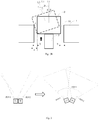
- Fig. 1 is a schematic view of a camera module controlled to incline in a related art.
- an electronic device may include a device body 1 and a camera module 2 arranged on the device body 1.
- the camera module 2 is inclined leftwards at an angle ⁇ .
- the device body 1 is provided with an accommodating space 10 for arranging the camera module 2 therein, and wherein a gap between the camera module 2 and a left inner wall of the accommodating space 10 should be no less than a, in order to meet an inclination requirement of the camera module 2.
- the camera module 2 cannot be inclined or cannot be inclined at the angle ⁇ under an impediment of the left inner wall. Similarly, if the camera module 2 is intended to be inclined rightwards at an angle ⁇ , a gap between the camera module 2 and a right inner wall of the accommodating space 10 should also be no less than a. Cases in other directions are similar, and will not be repeated herein.
- the gap between the camera module 2 and the accommodating space 10 is too large, the large gap will affect the aesthetics of the electronic device, and also facilitates foreign matters to enter easily, thus increasing difficulties of dustproof and waterproof, and hence reducing the reliability of the electronic device.
- FIG. 2A and Fig. 2B are schematic views of a camera module controlled to incline according to some embodiments of the present disclosure.
- an electronic device of the present disclosure includes a device body 1, a camera module 2 and an adjusting module 3.
- the device body 1 is provided with an accommodating space 10, and the camera module 2 is received and arranged in the accommodating space 10.
- the adjusting module 3 may be fitted with the camera module 2 to control the camera module 2 to switch between a first orientation and a second orientation, that is, from the first orientation to the second orientation, or from the second to the first orientation.
- the camera module 2 When the camera module 2 is at the first orientation, the camera module 2 is located in the accommodating space 10.
- the camera module 2 may be located at a bottom of the accommodating space 10, as illustrated in Fig. 2A , and in this case, a lens of the camera module 2 is oriented in a direction L1. Supposing the direction L1 is 0 degree, a direction on a right side of the direction L1 is a positive direction and a direction on a left side of the direction L1 is a negative direction, when a field-of-view (FOV) angle of the camera module 2 is 2 ⁇ , a first photographing range of the camera module 2 may be considered as [- ⁇ , ⁇ ].
- FOV field-of-view
- the adjusting module 3 may move the camera module 2 from the first orientation outwards from the accommodating space 10, thus moving at least a part of the camera module 2 outside the device body 1, such as a position illustrated in Fig. 2B . Furthermore, the adjusting module 3 may incline the camera module 2 (for example, inclined leftwards at an angle ⁇ ), such that the camera module 2 is switched to a second orientation represented with a dotted line in Fig. 2B . In this case, the lens of the camera module 2 is orientated in a L2 direction instead of the L1 direction, and the camera module 2 has a second photographing range at the second orientation, which may be denoted as [-( ⁇ + ⁇ ), ⁇ - ⁇ ]. Therefore, through the adjusting module 3 controlling the camera module 2 to switch between the first orientation and the second orientation, the photographing range provided by the camera module 2 may be changed, so as to meet a user's image capturing requirements.
- the adjusting module 2 first drives the at least part of the camera module 2 to move outside the device body 1 and then controls the camera module 2 to incline. Compared with directly controlling the camera module 2 to incline as illustrated in Fig. 1 , under the case of the same inclination with the angle ⁇ , a gap between the camera module 2 and the accommodating space 10 is reduced from a to b in the embodiment illustrated in Fig. 2B , and thus a width decrease of 2(a-b) in total along a left and right direction is achieved, because the gap illustrated in Fig. 1 needs to be fitted with the whole side wall of the camera module 2, while the gap illustrated in Fig. 2B only needs to be fitted with a part of the side wall of the camera module 2. If the adjusting module 2 even can move the camera module 2 completely out of the accommodating space 10, there may be nearly no gap between the camera module 2 and the accommodating space 10 (the gap may be as small as possible, as long as a movement of the camera module 2 is not hindered).
- the camera module 2 may include only one camera, or a plurality of cameras configured to move synchronously, and references may be made to the embodiment illustrated in Figs. 2A-2B .
- the inclination of the camera module 2 may change the photographing range, so as to meet the user's image capturing requirements in some scenes.
- a panoramic image capturing is realized by means of controlling the camera module 2 to move. The user only needs to concern how to keep the electronic device stationary without moving the electronic device, which helps to improve an image capturing stability and an image capturing quality.
- the camera module 2 may include a plurality of cameras, and the adjusting module 3 may drive some or all of the plurality of cameras to move, respectively.
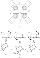
- Fig. 3 is a schematic view of controlling the plurality of cameras to move according to some embodiments of the present disclosure. As illustrated in Fig. 3 , assuming that the camera module 2 includes a camera 2A and a camera 2B, a left portion of Fig. 3 illustrates a case that the camera module 2 is at the first orientation, and a right portion of Fig.3 illustrates a case that the camera module 2 is at the second orientation.
- the lens of the camera 2A and the camera 2B both face forwards (i.e. upwards in Fig. 3 ), and a FOV1 of the camera 2A coincides with or substantially coincides with a FOV2 of the camera 2B (for example, a coincidence degree reaches a preset ratio), so as to achieve an image capturing effect such as a portrait with bokeh.
- the camera module 2 is at the second orientation, the camera 2A is inclined leftwards and the camera 2B is inclined rightwards, such that the FOV1 of the camera 2A deviates from the FOV2 of the camera 2B, and finally the FOV1 and the FOV2 are in an adjacent state or a partially overlapped state.
- the FOV1 and the FOV2 can form a combined field-of-view angle FOV3. That is, the combined field-of-view angle FOV3 may be formed after the camera 2A and camera 2B are inclined, respectively, and the FOV3 is larger than the single FOV1 or FOV2. It may be seen that the second photographing range of the camera module 2 at the second orientation is obviously larger than the first photographing range at the first orientation, so as to meet a wide-angle image capturing requirement of the user.
- only a part of the plurality of cameras included in the camera module 2 may only be inclined.
- the camera module 2 includes the camera 2A and the camera 2B mentioned above, only the camera 2A can be inclined leftwards and the camera 2B cannot be inclined, such that a relatively large combined field-of-view angle can be still formed by means of the inclination of the camera 2A.
- the plurality of cameras may be arranged in parallel, that is, arranged in sequence along a straight line.
- the camera module 2 includes three cameras, the three cameras may be arranged in sequence along an edge of the electronic device, such as a transverse edge or a longitudinal edge, which is not limited in the present disclosure.
- the plurality of cameras included in camera module 2 may be centrosymmetrically arranged around a central point.
- Fig. 4 is a schematic view illustrating a centrosymmetric arrangement of a plurality of cameras according to some embodiments of the present disclosure.
- the four cameras 2C-2F may be centrosymmetrically arranged around a central point O.
- the camera module 2 is switched from the first orientation to the second orientation, one end of each camera close to the central point O moves in a direction running away from the central point O and/or the other end of each camera far from the center point O moves in a direction approaching the central point O.
- Fig. 5 is a schematic view of an inclination of a camera according to some embodiments of the present disclosure.
- the camera 2C in Fig. 4 includes a right end close to the central point O, and the right end has a point A; the camera 2C includes a left end far from the central point O, and the left end has a point B; and the camera 2C also includes a point C located between the point A and the point B.
- panel (a) i.e., the left side portion of Fig.
- the camera 2C may rotate around an axis at the point B, such that the right end of the camera 2C close to the central point O moves leftwards, that is, in a direction running away from the central point O, and when inclined to a preset angle, the camera 2C occupies a space of a width a1 on the left side.
- panel (b) i.e., the middle portion of Fig.
- the camera 2C may rotate around an axis at the point A, such that the left end of the camera 2C far from the central point O moves rightwards, that is, in a direction approaching the central point O, and when inclined to the preset angle, the camera 2C occupies a space of a width a2 on the left side.
- panel (c) i.e., the right side portion of Fig.
- the camera 2C may rotate around an axis at the point C, such that the right end of the camera 2C close to the central point O moves leftwards, that is, in the direction running away from the central point O, while the left end of the camera 2C far from the central point O moves rightwards, that is, in the direction approaching the central point O.
- the camera 2C occupies a space of a width a3 on the left side.
- the space on the left side occupied by the camera 2C has a relationship: a2 ⁇ a3 ⁇ a1.
- the camera 2C occupies the largest space on the left side in Fig. 5 , panel (a) and the smallest space on the left in Fig. 5 , panel (b)
- the camera 2C does not occupy a bottom space in Fig. 5 , panel (a)
- the electronic device does not need to provide a corresponding reserved space for the camera 2C in a vertical direction.
- the camera 2C needs to occupy the bottom space in Fig. 5 , panel (b), such that the electronic device needs to provide the camera 2C with the corresponding reserved space in the vertical direction.
- the camera 2C needs to occupy a certain bottom space in Fig. 5 , panel (c), but the occupancy is better than that of the embodiment illustrated in Fig. 5 , panel (b).
- the adjusting module 3 in the present disclosure may first push at least a part of the camera module 2 out of the accommodating space 10 of the device body 1, such that the electronic device may form an available space in the vertical direction at the bottom of camera module 2, even if the electronic device does not provide the reserved space or only provides less reserved space, so as to meet a requirement of the camera module 2C occupying the space in the vertical direction, as described above.
- the camera module 2 may only be inclined according to the case in Fig. 5 , panel (a), thus causing a large lateral space occupation (the left side in Fig.
- the corresponding space in the vertical direction can be provided for the camera module 2, such that the camera module 2 can be inclined according to the case in Fig. 5 , panel (b) or panel 5(c), thus resulting in a small lateral space occupation.
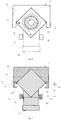
- Fig. 6 is an assembly view of a camera and an adjusting module according to some embodiments of the present disclosure.
- Fig. 7 is a sectional view corresponding to Fig. 6 .
- the camera 2C includes a photographing portion 21 and a fixing portion 22 connected with the photographing portion 21.
- the fixing portion 22 may be a flexible flat cable protruding outwards from the photographing portion 21.
- the photographing portion 21 is provided with a first group of protrusions 211 protruding along a first axis L3.
- the first axis L3 divides the photographing portion 21 into a first part (that is, a portion below the first axis L3 in Fig. 7 ) close to the fixing portion 22, and a second part (that is, a portion above the first axis L3 is Fig. 7 ) far from the fixing portion 22.
- the fixing portion 22 is provided with a second group of protrusions 221 protruding along a second axis L4.
- the second axis L4 divides the fixing portion 22 into a third part (that is, a portion above the second axis L4 in Fig. 7 ) close to the photographing portion 21, and a fourth part (that is, a portion below the second axis L4 is Fig.
- the adjusting module 3 includes a lifting part 31 configured to reciprocate along the vertical direction and fitted with the first part of the photographing portion 21, a lifting limit part 32 including a vertical sliding slot 321 fitted with the second group of protrusions 221, and an inclining limit part 33 fixedly arranged on the lifting part 31 and including a horizontal sliding slot 331 fitted with the first group of protrusions 211.
- Figs. 8-10 are schematic views of an adjusting module driving a camera to move according to some embodiments of the present disclosure.
- the camera module 2 is at the first orientation in the embodiment illustrated in Fig. 8 .
- the lifting part 31 is located at the lowest point
- the second group of protrusions 221 are located at a bottom of the vertical sliding slot 321
- the first group of protrusions 211 are located at a first end (that is, a right end in Figs. 8-10 ) of the horizontal sliding slot 331 far from the fixing portion 22.
- a movement of the camera 2C may be divided into following two stages.
- the lifting part 31 rises from the lowest point to an intermediate point (that is, a point between the lowest point and the highest point, but not necessarily a midpoint therebetween).
- the lifting part 31 directly pushes the first part of the photographing portion 21 to rise, and the photographing portion 21 further drives the fixing portion 22 to rise until the second group of protrusions 221 of the fixing portion 22 rise from the bottom of the vertical sliding slot 321 to a top thereof. Then, the fixing portion 22 is prevented from further rising under a limiting effect of the vertical sliding slot 321.
- the lifting part 31 continues rising from the intermediate point to the highest point.
- the lifting part 31 exerts an upward lifting force on the first part of the photographing portion 21, the photographing portion 21 is restrained by the fixing portion 22 and cannot continue rising, such that the first group of protrusions 211 rotate in the horizontal sliding slot 331 and move from the first end (that is, the right end in Figs. 8-10 ) of the horizontal sliding slot 331 far from the fixing portion 22 to a second end (that is, a left end in Figs. 8-10 ) of the horizontal sliding slot 331 close to the fixing portion 22.
- the photographing portion 21 is inclined leftwards around the first axis L3. It can be seen that, a fitting face between the lifting part 31 and the photographing portion 21 should not be beyond the first part, so as to ensure that the photographing portion 21 can be inclined around the first axis L3 in the second stage.
- the adjusting module 3 may include a plurality of the lifting parts 31 as illustrated in Figs. 6-10 , so as to be fitted with the plurality of cameras, respectively, such that the adjusting module 3 can control any one or more cameras to incline according to requirements, thus providing a high flexibility.
- the adjusting module 3 may include one lifting part 31 as illustrated in Fig. 11 , which is located among the plurality of cameras 2C ⁇ 2F included in the camera module 2, so as to be fitted with the photographing portions of the plurality of cameras 2C ⁇ 2F at the same time, thereby synchronously controlling all the cameras 2C ⁇ 2F to incline.
- a driving force may be provided to the adjusting module 3 in various ways.
- the driving force can be provided by a stepping motor.
- the electronic device may be provided with a driving member for the adjusting module 3, such that the user may exert an external force through the driving member so as to provide the driving force, or other ways may be used, which is not limited by the present disclosure.
- the stepping motor in order to reduce the occupancy of the vertical space in the electronic device and avoid increasing a thickness of the electronic device, the stepping motor may be arranged horizontally, such that a rotating shaft of the stepping motor is perpendicular to a lifting direction of the camera module 2.
- a driving direction of the rotating shaft may be converted to be parallel to the lifting direction by means of a worm structure or a helical gear, and then the rotating shaft is fitted with a lead screw.
- the lead screw may be fitted with a threaded hole 310 provided in the lifting part 31 as illustrated in Fig. 11 , so as to drive the lifting part 31 to reciprocate along the vertical direction.
- the fit between the first group of protrusions 211 and the horizontal sliding slot 331 as well as the fit between the second group of protrusions 221 and the vertical sliding slot 321 may also be replaced by other forms based on a fit between a sliding piece and a guide rail, a roller fit or a gear engagement and so on, which is not limited in the present disclosure.
- modules, circuits, device components, units, blocks, or portions may have modular configurations, or are composed of discrete components, but nonetheless can be referred to as "units,” “modules,” or “portions” in general.
- the "modules,” “circuits,” “components,” “blocks,” “portions,” or “units” referred to herein may or may not be in modular forms.
- the terms “one embodiment,” “some embodiments,” “example,” “specific example,” or “some examples,” and the like can indicate a specific feature described in connection with the embodiment or example, a structure, a material or feature included in at least one embodiment or example.
- the schematic representation of the above terms is not necessarily directed to the same embodiment or example.
Landscapes
- Engineering & Computer Science (AREA)
- Signal Processing (AREA)
- Multimedia (AREA)
- Physics & Mathematics (AREA)
- General Physics & Mathematics (AREA)
- Computing Systems (AREA)
- Theoretical Computer Science (AREA)
- Electromagnetism (AREA)
- Studio Devices (AREA)
- Accessories Of Cameras (AREA)
Abstract
Description
- The present disclosure relates to a field of camera technology, and more particularly, to an electronic device.
- More and more image capturing functions are realized by electronic devices. In some applications, an electronic device such as a mobile phone can use a more powerful camera to support more image capturing functions. In some applications, the number of the cameras used by the electronic device has increased from an original single one, to two, three or even more, referred to as a multi-camera solution.
- The present disclosure provides an electronic device for overcoming defects in the related art.
- According to embodiments of the present disclosure, there is provided an electronic device, including: a device body defining an accommodating space therein; a camera module arranged on the device body, and configured to be positioned in a first orientation and a second orientation, the camera module being configured to be located at the accommodating space of the device body and have a first photographing range at the first orientation, and to have a second photographing range at the second orientation; and an adjusting module arranged on the device body, and configured to drive the camera module at the first orientation to move outwards from the accommodating space, to move at least a part of the camera module outside the device body, and further to allow the camera module to be inclined to the second orientation.
- In some embodiments, the camera module comprises one camera.
- In some embodiments, the camera module comprises a plurality of cameras.
- In some embodiments, field-of-view angles of the plurality of cameras coincide or substantially coincide with each other under the first orientation, and correspond to the first photographing range.
- In some embodiments, field-of-view angles of the plurality of cameras are spliced into a combined field-of-view angle at the second orientation, the combined field-of-view angle is larger than a field-of-view angle of each camera, and the combined field-of-view angle corresponds to the second photographing range.
- In some embodiments, the plurality of cameras are arranged in parallel.
- In some embodiments, the plurality of cameras are centrosymmetrically arranged around a central point.
- In some embodiments, when the camera module is switched from the first orientation to the second orientation, an end of each camera close to the central point moves in a direction running away from the central point.
- In some embodiments, when the camera module is switched from the first orientation to the second orientation, an end of each camera far from the center point moves in a direction approaching the central point.
- In some embodiments, when the camera module is switched from the first orientation to the second orientation, one end of each camera close to the central point moves in a direction running away from the central point, and the other end of each camera far from the center point moves in a direction approaching the central point.
- In some embodiments, when the camera module is switched from the first orientation to the second orientation, a part of the plurality of cameras or all of the plurality of cameras are inclined.
- In some embodiments, the camera module comprises a camera, the camera comprises a photographing portion and a fixing portion connected with the photographing portion, the photographing portion is provided with a first group of protrusions protruding along a first axis, the first axis divides the photographing portion into a first part far from the fixing portion and a second part close to the fixing portion, the fixing portion is provided with a second group of protrusions protruding along a second axis, and the second axis divides the fixing portion into a third part close to the photographing portion and a fourth part far from the photographing portion. The adjusting module comprises: a lifting part configured to reciprocate along a vertical direction and fitted with the first part of the photographing portion; a lifting limit part comprising a vertical sliding slot fitted with the second group of protrusions, the second group of protrusions being configured to rise from a bottom of the vertical sliding slot to a top thereof during a process of the lifting part rising from a lowest point to an intermediate point; and an inclining limit part fixedly arranged on the lifting part and comprising a horizontal sliding slot fitted with the first group of protrusions, the first group of protrusions being configured to rise along with the lifting part during the process of the lifting part rising from the lowest point to the intermediate point, and further configured to rotate in the horizontal sliding slot and move from a first end of the horizontal sliding slot far from the fixing portion to a second end of the horizontal sliding slot close to the fixing portion during a process of the lifting part rising from the middle point to a highest point, such that the photographing portion is inclined around the first axis.
- In some embodiments, the fixing portion comprises a flexible flat cable protruding outwards from the photographing portion.
- In some embodiments, the lifting part is arranged at a bottom of the photographing portion.
- In some embodiments, the camera module comprises a plurality of cameras, and one lifting part is provided and arranged among the plurality of cameras of the camera module to be fitted with the photographing portions of the plurality of cameras simultaneously; or the camera module comprises a plurality of cameras, a plurality of lifting parts are provided, and each lifting part is fitted with the photographing portion of at least one of the plurality of cameras.
- The technical solution provided by embodiments of the present disclosure may include the following beneficial effects.
- The present disclosure can adjust the orientation of the camera module by providing the adjusting module fitted with the camera module, such that the camera module can achieve different photographing ranges in different orientations, thus expanding application scenes of the camera module, such as a wide angle image capturing or an ultra-wide angle image capturing by means of an ordinary lens. Moreover, in the process of the orientation adjustment, since the adjusting module moves at least a part of the camera module out of the device body, the space in the device body occupied by the camera module can be reduced, when the camera module is inclined. On one hand, the structure optimization and the space optimization among components inside the device body are facilitated. On the other hand, a too large gap is prevented from being formed around the camera module, thus optimizing the waterproof and dustproof performance of the electronic device.
- It is to be understood that both the foregoing general description and the following detailed description are exemplary and explanatory only and are not restrictive of the present disclosure, as claimed.
- The accompanying drawings, which are incorporated in and constitute a part of this specification, illustrate embodiments consistent with the present disclosure and, together with the description, serve to explain the principles of the present disclosure.
-
Fig. 1 is a schematic view of controlling a camera module to be inclined in a related art. -
Fig. 2A is a first schematic view of controlling a camera module to be inclined according to some embodiments of the present disclosure. -
Fig. 2B is a second schematic view of controlling a camera module to be inclined according to some embodiments of the present disclosure. -
Fig. 3 is a schematic view of controlling a plurality of cameras to move according to some embodiments of the present disclosure. -
Fig. 4 is a schematic view of a plurality of cameras centrosymmetrically arranged according to some embodiments of the present disclosure. -
Fig. 5 is a schematic view illustrating an inclination of a camera according to some embodiments of the present disclosure, in which three different cases are illustrated in panel (a), panel (b) and panel (c), respectively. -
Fig. 6 is an assembly view of a camera and an adjusting module according to some embodiments of the present disclosure. -
Fig. 7 is a sectional view corresponding toFig. 6 . -
Fig. 8 is a first schematic view of an adjusting module driving a camera to move according to some embodiments of the present disclosure. -
Fig. 9 is a second schematic view of an adjusting module driving a camera to move according to some embodiments of the present disclosure. -
Fig. 10 is a third schematic view of an adjusting module driving a camera to move according to some embodiments of the present disclosure. -
Fig. 11 is a schematic view of an adjusting module controlling a plurality of cameras to move according to some embodiments of the present disclosure. - References will now be made in detail to exemplary embodiments, examples of which are illustrated in the accompanying drawings. The following description refers to the accompanying drawings in which the same numbers in different drawings represent the same or similar elements, unless specified otherwise. The implementations set forth in the following description of the exemplary embodiments do not represent all implementations consistent with the present disclosure. Instead, they are merely examples of apparatuses and methods consistent with several aspects of the present disclosure as recited in the appended claims.
- Terms used in the present disclosure are only for the purpose of describing specific embodiments, and should not be construed to limit the present disclosure. As used in the present disclosure and the appended claims, "a" and "the" in a singular form intend to include a plural form, unless clearly indicated in the context otherwise. It should also be understood that, as used herein, the term "and/or" represents and contains any or all possible combinations of one or more associated listed items.
- It should be understood that, although terms such as first, second and third are used herein for describing various kinds of information, such information should not be limited to these terms. These terms are only used for distinguishing the same type of information from each other. For example, without departing from the scope of the present disclosure, a first information may also be called as a second information, and similarly, the second information may also be called as the first information. Depending on the context, the term "if' may be construed to mean "when" or "upon" or "in response to determining".
-
Fig. 1 is a schematic view of a camera module controlled to incline in a related art. As illustrated inFig. 1 , an electronic device may include adevice body 1 and acamera module 2 arranged on thedevice body 1. In some scenes, it is desirable to adjust and control thecamera module 2 such that thecamera module 2 can be inclined at a certain angle. For example, as illustrated inFig. 1 , thecamera module 2 is inclined leftwards at an angle α. Assuming that thedevice body 1 is provided with anaccommodating space 10 for arranging thecamera module 2 therein, and wherein a gap between thecamera module 2 and a left inner wall of theaccommodating space 10 should be no less than a, in order to meet an inclination requirement of thecamera module 2. Otherwise, thecamera module 2 cannot be inclined or cannot be inclined at the angle α under an impediment of the left inner wall. Similarly, if thecamera module 2 is intended to be inclined rightwards at an angle α, a gap between thecamera module 2 and a right inner wall of theaccommodating space 10 should also be no less than a. Cases in other directions are similar, and will not be repeated herein. - However, when the gap between the
camera module 2 and theaccommodating space 10 is too large, the large gap will affect the aesthetics of the electronic device, and also facilitates foreign matters to enter easily, thus increasing difficulties of dustproof and waterproof, and hence reducing the reliability of the electronic device. - Therefore, according to the inclination requirement of the
camera module 2, various embodiments of the present disclosure provide corresponding structural improvements to solve the problem of the excessive gap in the related art. Detailed descriptions will be made in combination with embodiments as follows. -
Fig. 2A andFig. 2B are schematic views of a camera module controlled to incline according to some embodiments of the present disclosure. As illustrated inFig. 2A andFig. 2B , an electronic device of the present disclosure includes adevice body 1, acamera module 2 and anadjusting module 3. Thedevice body 1 is provided with anaccommodating space 10, and thecamera module 2 is received and arranged in theaccommodating space 10. The adjustingmodule 3 may be fitted with thecamera module 2 to control thecamera module 2 to switch between a first orientation and a second orientation, that is, from the first orientation to the second orientation, or from the second to the first orientation. - When the
camera module 2 is at the first orientation, thecamera module 2 is located in theaccommodating space 10. For example, thecamera module 2 may be located at a bottom of theaccommodating space 10, as illustrated inFig. 2A , and in this case, a lens of thecamera module 2 is oriented in a direction L1. Supposing the direction L1 is 0 degree, a direction on a right side of the direction L1 is a positive direction and a direction on a left side of the direction L1 is a negative direction, when a field-of-view (FOV) angle of thecamera module 2 is 2β, a first photographing range of thecamera module 2 may be considered as [-β, β]. - The adjusting
module 3 may move thecamera module 2 from the first orientation outwards from theaccommodating space 10, thus moving at least a part of thecamera module 2 outside thedevice body 1, such as a position illustrated inFig. 2B . Furthermore, the adjustingmodule 3 may incline the camera module 2 (for example, inclined leftwards at an angle α), such that thecamera module 2 is switched to a second orientation represented with a dotted line inFig. 2B . In this case, the lens of thecamera module 2 is orientated in a L2 direction instead of the L1 direction, and thecamera module 2 has a second photographing range at the second orientation, which may be denoted as [-(β+α), β-α]. Therefore, through the adjustingmodule 3 controlling thecamera module 2 to switch between the first orientation and the second orientation, the photographing range provided by thecamera module 2 may be changed, so as to meet a user's image capturing requirements. - The adjusting
module 2 first drives the at least part of thecamera module 2 to move outside thedevice body 1 and then controls thecamera module 2 to incline. Compared with directly controlling thecamera module 2 to incline as illustrated inFig. 1 , under the case of the same inclination with the angle α, a gap between thecamera module 2 and theaccommodating space 10 is reduced from a to b in the embodiment illustrated inFig. 2B , and thus a width decrease of 2(a-b) in total along a left and right direction is achieved, because the gap illustrated inFig. 1 needs to be fitted with the whole side wall of thecamera module 2, while the gap illustrated inFig. 2B only needs to be fitted with a part of the side wall of thecamera module 2. If theadjusting module 2 even can move thecamera module 2 completely out of theaccommodating space 10, there may be nearly no gap between thecamera module 2 and the accommodating space 10 (the gap may be as small as possible, as long as a movement of thecamera module 2 is not hindered). - In some embodiments, the
camera module 2 may include only one camera, or a plurality of cameras configured to move synchronously, and references may be made to the embodiment illustrated inFigs. 2A-2B . In this case, although a size of the FOV formed by a single camera or a size of a combined FOV formed by the plurality of cameras of thecamera module 2 remains unchanged, the inclination of thecamera module 2 may change the photographing range, so as to meet the user's image capturing requirements in some scenes. For example, under the case that the electronic device does not move, a panoramic image capturing is realized by means of controlling thecamera module 2 to move. The user only needs to concern how to keep the electronic device stationary without moving the electronic device, which helps to improve an image capturing stability and an image capturing quality. - In some embodiments, the
camera module 2 may include a plurality of cameras, and theadjusting module 3 may drive some or all of the plurality of cameras to move, respectively. For example,Fig. 3 is a schematic view of controlling the plurality of cameras to move according to some embodiments of the present disclosure. As illustrated inFig. 3 , assuming that thecamera module 2 includes acamera 2A and acamera 2B, a left portion ofFig. 3 illustrates a case that thecamera module 2 is at the first orientation, and a right portion ofFig.3 illustrates a case that thecamera module 2 is at the second orientation. - When the
camera module 2 is at the first orientation, the lens of thecamera 2A and thecamera 2B both face forwards (i.e. upwards inFig. 3 ), and a FOV1 of thecamera 2A coincides with or substantially coincides with a FOV2 of thecamera 2B (for example, a coincidence degree reaches a preset ratio), so as to achieve an image capturing effect such as a portrait with bokeh. When thecamera module 2 is at the second orientation, thecamera 2A is inclined leftwards and thecamera 2B is inclined rightwards, such that the FOV1 of thecamera 2A deviates from the FOV2 of thecamera 2B, and finally the FOV1 and the FOV2 are in an adjacent state or a partially overlapped state. Therefore, the FOV1 and the FOV2 can form a combined field-of-view angle FOV3. That is, the combined field-of-view angle FOV3 may be formed after thecamera 2A andcamera 2B are inclined, respectively, and the FOV3 is larger than the single FOV1 or FOV2. It may be seen that the second photographing range of thecamera module 2 at the second orientation is obviously larger than the first photographing range at the first orientation, so as to meet a wide-angle image capturing requirement of the user. - As mentioned above, only a part of the plurality of cameras included in the
camera module 2 may only be inclined. For example, when thecamera module 2 includes thecamera 2A and thecamera 2B mentioned above, only thecamera 2A can be inclined leftwards and thecamera 2B cannot be inclined, such that a relatively large combined field-of-view angle can be still formed by means of the inclination of thecamera 2A. - When the number of the cameras included in the
camera module 2 is larger than two, the plurality of cameras may be arranged in parallel, that is, arranged in sequence along a straight line. For example, when thecamera module 2 includes three cameras, the three cameras may be arranged in sequence along an edge of the electronic device, such as a transverse edge or a longitudinal edge, which is not limited in the present disclosure. - In some embodiments, the plurality of cameras included in
camera module 2 may be centrosymmetrically arranged around a central point. For example,Fig. 4 is a schematic view illustrating a centrosymmetric arrangement of a plurality of cameras according to some embodiments of the present disclosure. As illustrated inFig. 4 , when thecamera module 2 includescameras cameras 2C-2F may be centrosymmetrically arranged around a central point O. Thus, when thecamera module 2 is switched from the first orientation to the second orientation, one end of each camera close to the central point O moves in a direction running away from the central point O and/or the other end of each camera far from the center point O moves in a direction approaching the central point O. -
Fig. 5 is a schematic view of an inclination of a camera according to some embodiments of the present disclosure. Taking thecamera 2C inFig. 4 as an example, thecamera 2C includes a right end close to the central point O, and the right end has a point A; thecamera 2C includes a left end far from the central point O, and the left end has a point B; and thecamera 2C also includes a point C located between the point A and the point B. InFig. 5 , panel (a) (i.e., the left side portion ofFig. 5 ), thecamera 2C may rotate around an axis at the point B, such that the right end of thecamera 2C close to the central point O moves leftwards, that is, in a direction running away from the central point O, and when inclined to a preset angle, thecamera 2C occupies a space of a width a1 on the left side. InFig. 5 , panel (b) (i.e., the middle portion ofFig. 5 ), thecamera 2C may rotate around an axis at the point A, such that the left end of thecamera 2C far from the central point O moves rightwards, that is, in a direction approaching the central point O, and when inclined to the preset angle, thecamera 2C occupies a space of a width a2 on the left side. InFig. 5 , panel (c) (i.e., the right side portion ofFig. 5 ), thecamera 2C may rotate around an axis at the point C, such that the right end of thecamera 2C close to the central point O moves leftwards, that is, in the direction running away from the central point O, while the left end of thecamera 2C far from the central point O moves rightwards, that is, in the direction approaching the central point O. When inclined to the preset angle, thecamera 2C occupies a space of a width a3 on the left side. - In the three cases illustrated in
Fig. 5 , the space on the left side occupied by thecamera 2C has a relationship: a2 < a3 < a1. Although thecamera 2C occupies the largest space on the left side inFig. 5 , panel (a) and the smallest space on the left inFig. 5 , panel (b), thecamera 2C does not occupy a bottom space inFig. 5 , panel (a), so the electronic device does not need to provide a corresponding reserved space for thecamera 2C in a vertical direction. However, thecamera 2C needs to occupy the bottom space inFig. 5 , panel (b), such that the electronic device needs to provide thecamera 2C with the corresponding reserved space in the vertical direction. Thecamera 2C needs to occupy a certain bottom space inFig. 5 , panel (c), but the occupancy is better than that of the embodiment illustrated inFig. 5 , panel (b). - Certainly, the adjusting
module 3 in the present disclosure may first push at least a part of thecamera module 2 out of theaccommodating space 10 of thedevice body 1, such that the electronic device may form an available space in the vertical direction at the bottom ofcamera module 2, even if the electronic device does not provide the reserved space or only provides less reserved space, so as to meet a requirement of thecamera module 2C occupying the space in the vertical direction, as described above. In other words, when the electronic device does not provide the reserved space in the vertical direction, if the at least part of thecamera module 2 is not pushed out of theaccommodating space 10 by the adjustingmodule 3, thecamera module 2 may only be inclined according to the case inFig. 5 , panel (a), thus causing a large lateral space occupation (the left side inFig. 5 ). However, if the at least part of thecamera module 2 is pushed out of theaccommodating space 10 is by the adjustingmodule 3, the corresponding space in the vertical direction can be provided for thecamera module 2, such that thecamera module 2 can be inclined according to the case inFig. 5 , panel (b) or panel 5(c), thus resulting in a small lateral space occupation. -
Fig. 6 is an assembly view of a camera and an adjusting module according to some embodiments of the present disclosure.Fig. 7 is a sectional view corresponding toFig. 6 . Still taking thecamera 2C included in thecamera module 2 as an example, as illustrated inFigs. 6-7 , thecamera 2C includes a photographingportion 21 and a fixingportion 22 connected with the photographingportion 21. For example, the fixingportion 22 may be a flexible flat cable protruding outwards from the photographingportion 21. The photographingportion 21 is provided with a first group ofprotrusions 211 protruding along a first axis L3. The first axis L3 divides the photographingportion 21 into a first part (that is, a portion below the first axis L3 inFig. 7 ) close to the fixingportion 22, and a second part (that is, a portion above the first axis L3 isFig. 7 ) far from the fixingportion 22. The fixingportion 22 is provided with a second group ofprotrusions 221 protruding along a second axis L4. The second axis L4 divides the fixingportion 22 into a third part (that is, a portion above the second axis L4 inFig. 7 ) close to the photographingportion 21, and a fourth part (that is, a portion below the second axis L4 isFig. 7 ) far from the photographingportion 21. The adjustingmodule 3 includes a liftingpart 31 configured to reciprocate along the vertical direction and fitted with the first part of the photographingportion 21, alifting limit part 32 including a vertical slidingslot 321 fitted with the second group ofprotrusions 221, and aninclining limit part 33 fixedly arranged on the liftingpart 31 and including a horizontal slidingslot 331 fitted with the first group ofprotrusions 211. - Accordingly,
Figs. 8-10 are schematic views of an adjusting module driving a camera to move according to some embodiments of the present disclosure. Thecamera module 2 is at the first orientation in the embodiment illustrated inFig. 8 . In this case, the liftingpart 31 is located at the lowest point, the second group ofprotrusions 221 are located at a bottom of the vertical slidingslot 321, and the first group ofprotrusions 211 are located at a first end (that is, a right end inFigs. 8-10 ) of the horizontal slidingslot 331 far from the fixingportion 22. Driven by the adjustingmodule 3, a movement of thecamera 2C may be divided into following two stages. - As illustrated in
Figs. 8-9 , in a first stage, the liftingpart 31 rises from the lowest point to an intermediate point (that is, a point between the lowest point and the highest point, but not necessarily a midpoint therebetween). During this process, the liftingpart 31 directly pushes the first part of the photographingportion 21 to rise, and the photographingportion 21 further drives the fixingportion 22 to rise until the second group ofprotrusions 221 of the fixingportion 22 rise from the bottom of the vertical slidingslot 321 to a top thereof. Then, the fixingportion 22 is prevented from further rising under a limiting effect of the vertical slidingslot 321. - As illustrated in
Figs. 9-10 , in a second stage, the liftingpart 31 continues rising from the intermediate point to the highest point. Although the liftingpart 31 exerts an upward lifting force on the first part of the photographingportion 21, the photographingportion 21 is restrained by the fixingportion 22 and cannot continue rising, such that the first group ofprotrusions 211 rotate in the horizontal slidingslot 331 and move from the first end (that is, the right end inFigs. 8-10 ) of the horizontal slidingslot 331 far from the fixingportion 22 to a second end (that is, a left end inFigs. 8-10 ) of the horizontal slidingslot 331 close to the fixingportion 22. During this process, the photographingportion 21 is inclined leftwards around the first axis L3. It can be seen that, a fitting face between the liftingpart 31 and the photographingportion 21 should not be beyond the first part, so as to ensure that the photographingportion 21 can be inclined around the first axis L3 in the second stage. - In some embodiments, when the
camera module 2 includes a plurality of cameras, the adjustingmodule 3 may include a plurality of the liftingparts 31 as illustrated inFigs. 6-10 , so as to be fitted with the plurality of cameras, respectively, such that theadjusting module 3 can control any one or more cameras to incline according to requirements, thus providing a high flexibility. - In some embodiments, when the
camera module 2 includes a plurality of cameras, the adjustingmodule 3 may include one liftingpart 31 as illustrated inFig. 11 , which is located among the plurality ofcameras 2C∼2F included in thecamera module 2, so as to be fitted with the photographing portions of the plurality ofcameras 2C∼2F at the same time, thereby synchronously controlling all thecameras 2C∼2F to incline. - In a technical solution of the present disclosure, a driving force may be provided to the
adjusting module 3 in various ways. For example, the driving force can be provided by a stepping motor. For another example, the electronic device may be provided with a driving member for theadjusting module 3, such that the user may exert an external force through the driving member so as to provide the driving force, or other ways may be used, which is not limited by the present disclosure. When the stepping motor is used, in order to reduce the occupancy of the vertical space in the electronic device and avoid increasing a thickness of the electronic device, the stepping motor may be arranged horizontally, such that a rotating shaft of the stepping motor is perpendicular to a lifting direction of thecamera module 2. Moreover, a driving direction of the rotating shaft may be converted to be parallel to the lifting direction by means of a worm structure or a helical gear, and then the rotating shaft is fitted with a lead screw. The lead screw may be fitted with a threadedhole 310 provided in the liftingpart 31 as illustrated inFig. 11 , so as to drive the liftingpart 31 to reciprocate along the vertical direction. - In addition, it is easy to understand that, the fit between the first group of
protrusions 211 and the horizontal slidingslot 331 as well as the fit between the second group ofprotrusions 221 and the vertical slidingslot 321 may also be replaced by other forms based on a fit between a sliding piece and a guide rail, a roller fit or a gear engagement and so on, which is not limited in the present disclosure. - It will be understood that when an element such as a layer, region, or other structure is referred to as being "on" or extending "onto" another element, it can be directly on or extend directly onto the other element or intervening elements can also be present. In contrast, when an element is referred to as being "directly on" or extending "directly onto" another element, there are no intervening elements present.
- Likewise, it will be understood that when an element such as a layer, region, or substrate is referred to as being "over" or extending "over" another element, it can be directly over or extend directly over the other element or intervening elements can also be present. In contrast, when an element is referred to as being "directly over" or extending "directly over" another element, there are no intervening elements present. It will also be understood that when an element is referred to as being "connected" or "coupled" to another element, it can be directly connected or coupled to the other element or intervening elements can be present. In contrast, when an element is referred to as being "directly connected" or "directly coupled" to another element, there are no intervening elements present.
- Relative terms such as "below" or "above" or "upper" or "lower" or "vertical" or "horizontal" can be used herein to describe a relationship of one element, layer, or region to another element, layer, or region as illustrated in the drawings. It will be understood that these terms and those discussed above are intended to encompass different orientations of the device in addition to the orientation depicted in the drawings.
- Unless otherwise defined, all terms (including technical and scientific terms) used herein have the same meaning as commonly understood by one of ordinary skill in the art to which this disclosure belongs. It will be further understood that terms used herein should be interpreted as having a meaning that is consistent with their meaning in the context of this specification and the relevant art and will not be interpreted in an idealized or overly formal sense unless expressly so defined herein.
- The various modules, circuits, device components, units, blocks, or portions may have modular configurations, or are composed of discrete components, but nonetheless can be referred to as "units," "modules," or "portions" in general. In other words, the "modules," "circuits," "components," "blocks," "portions," or "units" referred to herein may or may not be in modular forms.
- Other implementation solutions of the present disclosure will be apparent to those skilled in the art from consideration of the specification and practice of the present disclosure. This disclosure is intended to cover any variations, uses, or adaptations of the present disclosure following the general principles thereof and including such departures from the present disclosure as come within known or customary practice in the art. It is intended that the specification and examples be considered as some only, with a true scope of the present disclosure being indicated by the following claims.
- In the description of the present disclosure, the terms "one embodiment," "some embodiments," "example," "specific example," or "some examples," and the like can indicate a specific feature described in connection with the embodiment or example, a structure, a material or feature included in at least one embodiment or example. In the present disclosure, the schematic representation of the above terms is not necessarily directed to the same embodiment or example.
- Moreover, the particular features, structures, materials, or characteristics described can be combined in a suitable manner in any one or more embodiments or examples. In addition, various embodiments or examples described in the specification, as well as features of various embodiments or examples, can be combined and reorganized.
- While this specification contains many specific implementation details, these should not be construed as limitations on the scope of any claims, but rather as descriptions of features specific to particular implementations. Certain features that are described in this specification in the context of separate implementations can also be implemented in combination in a single implementation. Conversely, various features that are described in the context of a single implementation can also be implemented in multiple implementations separately or in any suitable subcombination.
- Moreover, although features can be described above as acting in certain combinations and even initially claimed as such, one or more features from a claimed combination can in some cases be excised from the combination, and the claimed combination can be directed to a subcombination or variation of a subcombination.
- Similarly, while operations are depicted in the drawings in a particular order, this should not be understood as requiring that such operations be performed in the particular order shown or in sequential order, or that all illustrated operations be performed, to achieve desirable results. In certain circumstances, multitasking and parallel processing can be advantageous. Moreover, the separation of various system components in the implementations described above should not be understood as requiring such separation in all implementations, and it should be understood that the described program components and systems can generally be integrated together in a single software product or packaged into multiple software products.
- As such, particular implementations of the subject matter have been described. Other implementations are within the scope of the following claims. In some cases, the actions recited in the claims can be performed in a different order and still achieve desirable results. In addition, the processes depicted in the accompanying figures do not necessarily require the particular order shown, or sequential order, to achieve desirable results. In certain implementations, multitasking or parallel processing can be utilized.
- It is intended that the specification and embodiments be considered as examples only. Some other embodiments of the present disclosure can be available to those skilled in the art upon consideration of the specification and practice of the various embodiments disclosed herein. The present application is intended to cover any variations, uses, or adaptations of the present disclosure following general principles of the present disclosure and include the common general knowledge or conventional technical means in the art without departing from the present disclosure. The specification and examples can be shown as illustrative only, and the true scope of the disclosure are indicated by the following claims.
Claims (15)
- An electronic device, comprising:a device body (1) defining an accommodating space (10) therein;a camera module (2) arranged on the device body (1), and configured to be positioned to be a first orientation and a second orientation, the camera module (2) being configured to be located at the accommodating space (10) of the device body (1) and have a first photographing range at the first orientation, and to have a second photographing range at the second orientation; andan adjusting module (3) arranged on the device body (1), and configured to drive the camera module (2) at the first orientation to move outwards from the accommodating space (10), to move at least a part of the camera module (2) outside the device body (1), and further to allow the camera module (2) to be inclined to the second orientation.
- The electronic device according to claim 1, wherein the camera module (2) comprises one camera.
- The electronic device according to claim 1, wherein the camera module (2) comprises a plurality of cameras.
- The electronic device according to claim 3, wherein field-of-view angles of the plurality of cameras coincide or substantially coincide with each other under the first orientation, and correspond to the first photographing range.
- The electronic device according to claim 3 or 4, wherein field-of-view angles of the plurality of cameras are spliced into a combined field-of-view angle at the second orientation, the combined field-of-view angle is larger than a field-of-view angle of each camera, and the combined field-of-view angle corresponds to the second photographing range.
- The electronic device according to anyone of claims 3 to 5, wherein the plurality of cameras are arranged in parallel.
- The electronic device according to anyone of claims 3 to 6, wherein the plurality of cameras are centrosymmetrically arranged around a central point (O).
- The electronic device according to claim 7, wherein when the camera module (2) is switched from the first orientation to the second orientation, an end of each camera close to the central point (O) moves in a direction running away from the central point (O).
- The electronic device according to claim 7 or 8, wherein when the camera module (2) is switched from the first orientation to the second orientation, an end of each camera far from the central point (O) moves in a direction approaching the central point (O).
- The electronic device according to anyone of claims 7 to 9, wherein when the camera module (2) is switched from the first orientation to the second orientation, one end of each camera close to the central point (O) moves in a direction running away from the central point (O), and the other end of each camera far from the central point (O) moves in a direction approaching the central point (O).
- The electronic device according to anyone of claims 3 to 10, wherein when the camera module (2) is switched from the first orientation to the second orientation, a part of the plurality of cameras or all the plurality of cameras are inclined.
- The electronic device according to claim 1, wherein,
the camera module (2) comprises a camera, the camera comprises a photographing portion (21) and a fixing portion (22) connected with the photographing portion (21), the photographing portion (21) is provided with a first group of protrusions (211) protruding along a first axis (L3), the first axis (L3) divides the photographing portion (21) into a first part far from the fixing portion (22) and a second part close to the fixing portion (22), the fixing portion (22) is provided with a second group of protrusions (221) protruding along a second axis (L4), and the second axis (L4) divides the fixing portion (22) into a third part close to the photographing portion (21) and a fourth part far from the photographing portion (21);
the adjusting module (3) comprises:a lifting part (31) configured to reciprocate along a vertical direction and fitted with the first part of the photographing portion (21);a lifting limit part (32) comprising a vertical sliding slot (321) fitted with the second group of protrusions (221), the second group of protrusions (221) being configured to rise from a bottom of the vertical sliding slot (321) to a top thereof during a process of the lifting part (31) rising from a lowest point to an intermediate point; andan inclining limit part (33) fixedly arranged on the lifting part (31) and comprising a horizontal sliding slot (331) fitted with the first group of protrusions (211), the first group of protrusions (211) being configured to rise along with the lifting part (31) during the process of the lifting part (31) rising from the lowest point to the intermediate point, and further configured to rotate in the horizontal sliding slot (331) and move from a first end of the horizontal sliding slot (331) far from the fixing portion (22) to a second end of the horizontal sliding slot (331) close to the fixing portion (22) during a process of the lifting part (31) rising from the middle point to a highest point, such that the photographing portion (21) is inclined around the first axis (L3). - The electronic device according to claim 12, wherein the fixing portion (22) comprises a flexible flat cable protruding outwards from the photographing portion (21).
- The electronic device according to claim 12 or 13, wherein the lifting part (31) is arranged at a bottom of the photographing portion (21).
- The electronic device according to anyone of claims 12 to 14, wherein the camera module (2) comprises a plurality of cameras, and one lifting part (31) is provided and arranged among the plurality of cameras of the camera module (2) to be fitted with the photographing portions (21) of the plurality of cameras simultaneously; or
wherein the camera module (2) comprises a plurality of cameras, a plurality of lifting parts (31) are provided, and each lifting part (31) is fitted with the photographing portion (21) of at least one of the plurality of cameras.
Applications Claiming Priority (1)
| Application Number | Priority Date | Filing Date | Title |
|---|---|---|---|
| CN201910388533.4A CN111917945B (en) | 2019-05-10 | 2019-05-10 | electronic devices |
Publications (2)
| Publication Number | Publication Date |
|---|---|
| EP3737081A1 true EP3737081A1 (en) | 2020-11-11 |
| EP3737081B1 EP3737081B1 (en) | 2022-09-14 |
Family
ID=68835092
Family Applications (1)
| Application Number | Title | Priority Date | Filing Date |
|---|---|---|---|
| EP19214368.3A Active EP3737081B1 (en) | 2019-05-10 | 2019-12-09 | Electronic device |
Country Status (3)
| Country | Link |
|---|---|
| US (1) | US10944854B2 (en) |
| EP (1) | EP3737081B1 (en) |
| CN (1) | CN111917945B (en) |
Citations (3)
| Publication number | Priority date | Publication date | Assignee | Title |
|---|---|---|---|---|
| EP1085769A2 (en) * | 1999-09-15 | 2001-03-21 | Sharp Kabushiki Kaisha | Stereoscopic image pickup apparatus |
| US20130033584A1 (en) * | 2010-04-12 | 2013-02-07 | Ja-Won Seo | Stereo camera module apparatus and method |
| US20170026634A1 (en) * | 2014-03-12 | 2017-01-26 | Ram Srikanth Mirlay | Multi-planar camera apparatus |
Family Cites Families (18)
| Publication number | Priority date | Publication date | Assignee | Title |
|---|---|---|---|---|
| US7352387B2 (en) * | 2001-04-05 | 2008-04-01 | Scaler Corporation | Camera with positioning device used to capture magnified and demagnified images |
| JP2004157357A (en) * | 2002-11-07 | 2004-06-03 | Matsushita Electric Ind Co Ltd | Imaging device |
| DE102015117775A1 (en) * | 2015-04-30 | 2016-11-03 | Huf Hülsbeck & Fürst Gmbh & Co. Kg | Camera device for motor vehicles |
| KR101672491B1 (en) * | 2015-09-24 | 2016-11-03 | (주) 씨앤피 | Portable electronic image magnifier |
| CN105430131B (en) * | 2015-12-23 | 2018-11-02 | 惠州Tcl移动通信有限公司 | A kind of the adjustable-angle CCD camera assembly and mobile phone of mobile phone |
| CN205232326U (en) * | 2015-12-25 | 2016-05-11 | 威海新北洋数码科技股份有限公司 | Camera subassembly and use self -service equipment of this subassembly |
| CN105791650B (en) * | 2016-03-30 | 2018-12-25 | 广州力富视频科技有限公司 | Wireless comprehensive recording apparatus of finding a view |
| CN205545610U (en) * | 2016-04-27 | 2016-08-31 | 零度智控(北京)智能科技有限公司 | Angularly adjustable camera and unmanned aerial vehicle |
| WO2018026951A1 (en) * | 2016-08-02 | 2018-02-08 | Parto Inc. | Rapid real-time large depth of field, whole body, multi-spectral optical imaging for skin surveillance and photography |
| CN205987111U (en) * | 2016-08-30 | 2017-02-22 | 江山海维科技有限公司 | But height -adjusting's surveillance camera head |
| WO2018082061A1 (en) * | 2016-11-04 | 2018-05-11 | 东莞佩斯讯光电技术有限公司 | Camera module and control method on the basis of lens tilting controllable motor and fast focus sensor |
| CN106982314B (en) * | 2017-03-30 | 2020-03-20 | 联想(北京)有限公司 | Shooting adjusting device and adjusting method thereof |
| CN109656311A (en) * | 2017-10-10 | 2019-04-19 | 陈旭 | Another tablet computer |
| CN108388314A (en) * | 2018-04-04 | 2018-08-10 | 深圳天珑无线科技有限公司 | A kind of electronic equipment and its CCD camera assembly |
| CN108679405B (en) * | 2018-08-09 | 2024-07-26 | 杭州国迈电子科技有限公司 | Camera adjustment mechanism on display screen |
| CN208797996U (en) * | 2018-09-07 | 2019-04-26 | Oppo广东移动通信有限公司 | mobile terminal |
| CN109654340A (en) * | 2019-01-08 | 2019-04-19 | 陕西理工大学 | A kind of angle adjustment device for photography and vedio recording |
| CN209642809U (en) * | 2019-05-10 | 2019-11-15 | 北京小米移动软件有限公司 | Electronic equipment |
-
2019
- 2019-05-10 CN CN201910388533.4A patent/CN111917945B/en active Active
- 2019-11-29 US US16/699,257 patent/US10944854B2/en active Active
- 2019-12-09 EP EP19214368.3A patent/EP3737081B1/en active Active
Patent Citations (3)
| Publication number | Priority date | Publication date | Assignee | Title |
|---|---|---|---|---|
| EP1085769A2 (en) * | 1999-09-15 | 2001-03-21 | Sharp Kabushiki Kaisha | Stereoscopic image pickup apparatus |
| US20130033584A1 (en) * | 2010-04-12 | 2013-02-07 | Ja-Won Seo | Stereo camera module apparatus and method |
| US20170026634A1 (en) * | 2014-03-12 | 2017-01-26 | Ram Srikanth Mirlay | Multi-planar camera apparatus |
Also Published As
| Publication number | Publication date |
|---|---|
| US10944854B2 (en) | 2021-03-09 |
| CN111917945A (en) | 2020-11-10 |
| EP3737081B1 (en) | 2022-09-14 |
| US20200358889A1 (en) | 2020-11-12 |
| CN111917945B (en) | 2025-08-05 |
Similar Documents
| Publication | Publication Date | Title |
|---|---|---|
| CN101363957B (en) | Projection image display apparatus | |
| US9081260B2 (en) | Dome camera | |
| CN113572918B (en) | Periscopic continuous light-variable module and corresponding multi-camera module | |
| KR102367554B1 (en) | Apparatus for driving zoom lens | |
| KR102799350B1 (en) | Lens assembly and Camera module comprising the same | |
| US20060164540A1 (en) | Zoom lens system and camera having the same | |
| US9055199B2 (en) | Autofocus camera system and control method thereof | |
| US20060056063A1 (en) | Image pickup apparatus | |
| KR20190121953A (en) | Camera module and flat-type coil for long stroke | |
| CN209642809U (en) | Electronic equipment | |
| KR101594301B1 (en) | Apparatus for driving lens | |
| CN101419328A (en) | Lens module, camera module and portable electronic products | |
| EP3737081A1 (en) | Electronic device | |
| US8373934B2 (en) | Lens barrel | |
| CN204925578U (en) | Two light filter cutaway seats | |
| US20070086772A1 (en) | Image capturing apparatus | |
| CN115461679B (en) | Camera module and mobile terminal | |
| KR102590894B1 (en) | Ghost reduction device, imaging device equipped with the same, ghost reduction method, and imaging optical device | |
| JP2008026712A (en) | Imaging apparatus with a plurality of optical systems | |
| US11175474B2 (en) | Lens barrel | |
| KR20210081385A (en) | imaging module | |
| US20240353659A1 (en) | Camera module and electronic device | |
| CN101688965B (en) | Single motor and clutch unit for independently adjusting two lens assemblies | |
| WO2023016276A1 (en) | Camera module | |
| CN117008396A (en) | Telescopic lens and camera module with same |
Legal Events
| Date | Code | Title | Description |
|---|---|---|---|
| PUAI | Public reference made under article 153(3) epc to a published international application that has entered the european phase |
Free format text: ORIGINAL CODE: 0009012 |
|
| STAA | Information on the status of an ep patent application or granted ep patent |
Free format text: STATUS: THE APPLICATION HAS BEEN PUBLISHED |
|
| AK | Designated contracting states |
Kind code of ref document: A1 Designated state(s): AL AT BE BG CH CY CZ DE DK EE ES FI FR GB GR HR HU IE IS IT LI LT LU LV MC MK MT NL NO PL PT RO RS SE SI SK SM TR |
|
| AX | Request for extension of the european patent |
Extension state: BA ME |
|
| STAA | Information on the status of an ep patent application or granted ep patent |
Free format text: STATUS: REQUEST FOR EXAMINATION WAS MADE |
|
| 17P | Request for examination filed |
Effective date: 20210429 |
|
| RBV | Designated contracting states (corrected) |
Designated state(s): AL AT BE BG CH CY CZ DE DK EE ES FI FR GB GR HR HU IE IS IT LI LT LU LV MC MK MT NL NO PL PT RO RS SE SI SK SM TR |
|
| GRAP | Despatch of communication of intention to grant a patent |
Free format text: ORIGINAL CODE: EPIDOSNIGR1 |
|
| STAA | Information on the status of an ep patent application or granted ep patent |
Free format text: STATUS: GRANT OF PATENT IS INTENDED |
|
| RIC1 | Information provided on ipc code assigned before grant |
Ipc: G03B 37/04 20060101ALI20220318BHEP Ipc: H04N 5/247 20060101ALI20220318BHEP Ipc: H04N 5/225 20060101AFI20220318BHEP |
|
| INTG | Intention to grant announced |
Effective date: 20220419 |
|
| GRAS | Grant fee paid |
Free format text: ORIGINAL CODE: EPIDOSNIGR3 |
|
| GRAA | (expected) grant |
Free format text: ORIGINAL CODE: 0009210 |
|
| STAA | Information on the status of an ep patent application or granted ep patent |
Free format text: STATUS: THE PATENT HAS BEEN GRANTED |
|
| AK | Designated contracting states |
Kind code of ref document: B1 Designated state(s): AL AT BE BG CH CY CZ DE DK EE ES FI FR GB GR HR HU IE IS IT LI LT LU LV MC MK MT NL NO PL PT RO RS SE SI SK SM TR |
|
| REG | Reference to a national code |
Ref country code: GB Ref legal event code: FG4D |
|
| REG | Reference to a national code |
Ref country code: CH Ref legal event code: EP |
|
| REG | Reference to a national code |
Ref country code: DE Ref legal event code: R096 Ref document number: 602019019547 Country of ref document: DE |
|
| REG | Reference to a national code |
Ref country code: IE Ref legal event code: FG4D |
|
| REG | Reference to a national code |
Ref country code: AT Ref legal event code: REF Ref document number: 1519405 Country of ref document: AT Kind code of ref document: T Effective date: 20221015 |
|
| REG | Reference to a national code |
Ref country code: DE Ref legal event code: R079 Ref document number: 602019019547 Country of ref document: DE Free format text: PREVIOUS MAIN CLASS: H04N0005225000 Ipc: H04N0023000000 |
|
| REG | Reference to a national code |
Ref country code: LT Ref legal event code: MG9D |
|
| REG | Reference to a national code |
Ref country code: NL Ref legal event code: MP Effective date: 20220914 |
|
| PG25 | Lapsed in a contracting state [announced via postgrant information from national office to epo] |
Ref country code: SE Free format text: LAPSE BECAUSE OF FAILURE TO SUBMIT A TRANSLATION OF THE DESCRIPTION OR TO PAY THE FEE WITHIN THE PRESCRIBED TIME-LIMIT Effective date: 20220914 Ref country code: RS Free format text: LAPSE BECAUSE OF FAILURE TO SUBMIT A TRANSLATION OF THE DESCRIPTION OR TO PAY THE FEE WITHIN THE PRESCRIBED TIME-LIMIT Effective date: 20220914 Ref country code: NO Free format text: LAPSE BECAUSE OF FAILURE TO SUBMIT A TRANSLATION OF THE DESCRIPTION OR TO PAY THE FEE WITHIN THE PRESCRIBED TIME-LIMIT Effective date: 20221214 Ref country code: LV Free format text: LAPSE BECAUSE OF FAILURE TO SUBMIT A TRANSLATION OF THE DESCRIPTION OR TO PAY THE FEE WITHIN THE PRESCRIBED TIME-LIMIT Effective date: 20220914 Ref country code: LT Free format text: LAPSE BECAUSE OF FAILURE TO SUBMIT A TRANSLATION OF THE DESCRIPTION OR TO PAY THE FEE WITHIN THE PRESCRIBED TIME-LIMIT Effective date: 20220914 Ref country code: FI Free format text: LAPSE BECAUSE OF FAILURE TO SUBMIT A TRANSLATION OF THE DESCRIPTION OR TO PAY THE FEE WITHIN THE PRESCRIBED TIME-LIMIT Effective date: 20220914 |
|
| REG | Reference to a national code |
Ref country code: AT Ref legal event code: MK05 Ref document number: 1519405 Country of ref document: AT Kind code of ref document: T Effective date: 20220914 |
|
| PG25 | Lapsed in a contracting state [announced via postgrant information from national office to epo] |
Ref country code: HR Free format text: LAPSE BECAUSE OF FAILURE TO SUBMIT A TRANSLATION OF THE DESCRIPTION OR TO PAY THE FEE WITHIN THE PRESCRIBED TIME-LIMIT Effective date: 20220914 Ref country code: GR Free format text: LAPSE BECAUSE OF FAILURE TO SUBMIT A TRANSLATION OF THE DESCRIPTION OR TO PAY THE FEE WITHIN THE PRESCRIBED TIME-LIMIT Effective date: 20221215 |
|
| PG25 | Lapsed in a contracting state [announced via postgrant information from national office to epo] |
Ref country code: SM Free format text: LAPSE BECAUSE OF FAILURE TO SUBMIT A TRANSLATION OF THE DESCRIPTION OR TO PAY THE FEE WITHIN THE PRESCRIBED TIME-LIMIT Effective date: 20220914 Ref country code: RO Free format text: LAPSE BECAUSE OF FAILURE TO SUBMIT A TRANSLATION OF THE DESCRIPTION OR TO PAY THE FEE WITHIN THE PRESCRIBED TIME-LIMIT Effective date: 20220914 Ref country code: PT Free format text: LAPSE BECAUSE OF FAILURE TO SUBMIT A TRANSLATION OF THE DESCRIPTION OR TO PAY THE FEE WITHIN THE PRESCRIBED TIME-LIMIT Effective date: 20230116 Ref country code: ES Free format text: LAPSE BECAUSE OF FAILURE TO SUBMIT A TRANSLATION OF THE DESCRIPTION OR TO PAY THE FEE WITHIN THE PRESCRIBED TIME-LIMIT Effective date: 20220914 Ref country code: CZ Free format text: LAPSE BECAUSE OF FAILURE TO SUBMIT A TRANSLATION OF THE DESCRIPTION OR TO PAY THE FEE WITHIN THE PRESCRIBED TIME-LIMIT Effective date: 20220914 Ref country code: AT Free format text: LAPSE BECAUSE OF FAILURE TO SUBMIT A TRANSLATION OF THE DESCRIPTION OR TO PAY THE FEE WITHIN THE PRESCRIBED TIME-LIMIT Effective date: 20220914 |
|
| PG25 | Lapsed in a contracting state [announced via postgrant information from national office to epo] |
Ref country code: SK Free format text: LAPSE BECAUSE OF FAILURE TO SUBMIT A TRANSLATION OF THE DESCRIPTION OR TO PAY THE FEE WITHIN THE PRESCRIBED TIME-LIMIT Effective date: 20220914 Ref country code: PL Free format text: LAPSE BECAUSE OF FAILURE TO SUBMIT A TRANSLATION OF THE DESCRIPTION OR TO PAY THE FEE WITHIN THE PRESCRIBED TIME-LIMIT Effective date: 20220914 Ref country code: IS Free format text: LAPSE BECAUSE OF FAILURE TO SUBMIT A TRANSLATION OF THE DESCRIPTION OR TO PAY THE FEE WITHIN THE PRESCRIBED TIME-LIMIT Effective date: 20230114 Ref country code: EE Free format text: LAPSE BECAUSE OF FAILURE TO SUBMIT A TRANSLATION OF THE DESCRIPTION OR TO PAY THE FEE WITHIN THE PRESCRIBED TIME-LIMIT Effective date: 20220914 |
|
| REG | Reference to a national code |
Ref country code: DE Ref legal event code: R097 Ref document number: 602019019547 Country of ref document: DE |
|
| P01 | Opt-out of the competence of the unified patent court (upc) registered |
Effective date: 20230523 |
|
| PG25 | Lapsed in a contracting state [announced via postgrant information from national office to epo] |
Ref country code: NL Free format text: LAPSE BECAUSE OF FAILURE TO SUBMIT A TRANSLATION OF THE DESCRIPTION OR TO PAY THE FEE WITHIN THE PRESCRIBED TIME-LIMIT Effective date: 20220914 Ref country code: AL Free format text: LAPSE BECAUSE OF FAILURE TO SUBMIT A TRANSLATION OF THE DESCRIPTION OR TO PAY THE FEE WITHIN THE PRESCRIBED TIME-LIMIT Effective date: 20220914 |
|
| PLBE | No opposition filed within time limit |
Free format text: ORIGINAL CODE: 0009261 |
|
| STAA | Information on the status of an ep patent application or granted ep patent |
Free format text: STATUS: NO OPPOSITION FILED WITHIN TIME LIMIT |
|
| PG25 | Lapsed in a contracting state [announced via postgrant information from national office to epo] |
Ref country code: DK Free format text: LAPSE BECAUSE OF FAILURE TO SUBMIT A TRANSLATION OF THE DESCRIPTION OR TO PAY THE FEE WITHIN THE PRESCRIBED TIME-LIMIT Effective date: 20220914 |
|
| REG | Reference to a national code |
Ref country code: CH Ref legal event code: PL |
|
| 26N | No opposition filed |
Effective date: 20230615 |
|
| REG | Reference to a national code |
Ref country code: BE Ref legal event code: MM Effective date: 20221231 |
|
| PG25 | Lapsed in a contracting state [announced via postgrant information from national office to epo] |
Ref country code: SI Free format text: LAPSE BECAUSE OF FAILURE TO SUBMIT A TRANSLATION OF THE DESCRIPTION OR TO PAY THE FEE WITHIN THE PRESCRIBED TIME-LIMIT Effective date: 20220914 Ref country code: LU Free format text: LAPSE BECAUSE OF NON-PAYMENT OF DUE FEES Effective date: 20221209 |
|
| PG25 | Lapsed in a contracting state [announced via postgrant information from national office to epo] |
Ref country code: LI Free format text: LAPSE BECAUSE OF NON-PAYMENT OF DUE FEES Effective date: 20221231 Ref country code: IE Free format text: LAPSE BECAUSE OF NON-PAYMENT OF DUE FEES Effective date: 20221209 Ref country code: CH Free format text: LAPSE BECAUSE OF NON-PAYMENT OF DUE FEES Effective date: 20221231 |
|
| PG25 | Lapsed in a contracting state [announced via postgrant information from national office to epo] |
Ref country code: BE Free format text: LAPSE BECAUSE OF NON-PAYMENT OF DUE FEES Effective date: 20221231 |
|
| PG25 | Lapsed in a contracting state [announced via postgrant information from national office to epo] |
Ref country code: CY Free format text: LAPSE BECAUSE OF FAILURE TO SUBMIT A TRANSLATION OF THE DESCRIPTION OR TO PAY THE FEE WITHIN THE PRESCRIBED TIME-LIMIT Effective date: 20220914 |
|
| PG25 | Lapsed in a contracting state [announced via postgrant information from national office to epo] |
Ref country code: MK Free format text: LAPSE BECAUSE OF FAILURE TO SUBMIT A TRANSLATION OF THE DESCRIPTION OR TO PAY THE FEE WITHIN THE PRESCRIBED TIME-LIMIT Effective date: 20220914 Ref country code: IT Free format text: LAPSE BECAUSE OF FAILURE TO SUBMIT A TRANSLATION OF THE DESCRIPTION OR TO PAY THE FEE WITHIN THE PRESCRIBED TIME-LIMIT Effective date: 20220914 Ref country code: HU Free format text: LAPSE BECAUSE OF FAILURE TO SUBMIT A TRANSLATION OF THE DESCRIPTION OR TO PAY THE FEE WITHIN THE PRESCRIBED TIME-LIMIT; INVALID AB INITIO Effective date: 20191209 |
|
| PG25 | Lapsed in a contracting state [announced via postgrant information from national office to epo] |
Ref country code: MC Free format text: LAPSE BECAUSE OF FAILURE TO SUBMIT A TRANSLATION OF THE DESCRIPTION OR TO PAY THE FEE WITHIN THE PRESCRIBED TIME-LIMIT Effective date: 20220914 |
|
| PG25 | Lapsed in a contracting state [announced via postgrant information from national office to epo] |
Ref country code: TR Free format text: LAPSE BECAUSE OF FAILURE TO SUBMIT A TRANSLATION OF THE DESCRIPTION OR TO PAY THE FEE WITHIN THE PRESCRIBED TIME-LIMIT Effective date: 20220914 Ref country code: MC Free format text: LAPSE BECAUSE OF FAILURE TO SUBMIT A TRANSLATION OF THE DESCRIPTION OR TO PAY THE FEE WITHIN THE PRESCRIBED TIME-LIMIT Effective date: 20220914 |
|
| PG25 | Lapsed in a contracting state [announced via postgrant information from national office to epo] |
Ref country code: BG Free format text: LAPSE BECAUSE OF FAILURE TO SUBMIT A TRANSLATION OF THE DESCRIPTION OR TO PAY THE FEE WITHIN THE PRESCRIBED TIME-LIMIT Effective date: 20220914 |
|
| PG25 | Lapsed in a contracting state [announced via postgrant information from national office to epo] |
Ref country code: MT Free format text: LAPSE BECAUSE OF FAILURE TO SUBMIT A TRANSLATION OF THE DESCRIPTION OR TO PAY THE FEE WITHIN THE PRESCRIBED TIME-LIMIT Effective date: 20220914 |
|
| PGFP | Annual fee paid to national office [announced via postgrant information from national office to epo] |
Ref country code: DE Payment date: 20251126 Year of fee payment: 7 |
|
| PGFP | Annual fee paid to national office [announced via postgrant information from national office to epo] |
Ref country code: GB Payment date: 20251127 Year of fee payment: 7 |
|
| PGFP | Annual fee paid to national office [announced via postgrant information from national office to epo] |
Ref country code: FR Payment date: 20251124 Year of fee payment: 7 |