EP3737036B1 - Firewall configuration and message sending method and device - Google Patents
Firewall configuration and message sending method and device Download PDFInfo
- Publication number
- EP3737036B1 EP3737036B1 EP18903293.1A EP18903293A EP3737036B1 EP 3737036 B1 EP3737036 B1 EP 3737036B1 EP 18903293 A EP18903293 A EP 18903293A EP 3737036 B1 EP3737036 B1 EP 3737036B1
- Authority
- EP
- European Patent Office
- Prior art keywords
- firewall
- subnet
- virtual machine
- policy information
- compute node
- Prior art date
- Legal status (The legal status is an assumption and is not a legal conclusion. Google has not performed a legal analysis and makes no representation as to the accuracy of the status listed.)
- Active
Links
Images




Classifications
-
- H—ELECTRICITY
- H04—ELECTRIC COMMUNICATION TECHNIQUE
- H04L—TRANSMISSION OF DIGITAL INFORMATION, e.g. TELEGRAPHIC COMMUNICATION
- H04L63/00—Network architectures or network communication protocols for network security
- H04L63/02—Network architectures or network communication protocols for network security for separating internal from external traffic, e.g. firewalls
- H04L63/0227—Filtering policies
-
- H—ELECTRICITY
- H04—ELECTRIC COMMUNICATION TECHNIQUE
- H04L—TRANSMISSION OF DIGITAL INFORMATION, e.g. TELEGRAPHIC COMMUNICATION
- H04L63/00—Network architectures or network communication protocols for network security
- H04L63/02—Network architectures or network communication protocols for network security for separating internal from external traffic, e.g. firewalls
- H04L63/0227—Filtering policies
- H04L63/0263—Rule management
-
- H—ELECTRICITY
- H04—ELECTRIC COMMUNICATION TECHNIQUE
- H04L—TRANSMISSION OF DIGITAL INFORMATION, e.g. TELEGRAPHIC COMMUNICATION
- H04L63/00—Network architectures or network communication protocols for network security
- H04L63/02—Network architectures or network communication protocols for network security for separating internal from external traffic, e.g. firewalls
- H04L63/0209—Architectural arrangements, e.g. perimeter networks or demilitarized zones
- H04L63/0218—Distributed architectures, e.g. distributed firewalls
-
- G—PHYSICS
- G06—COMPUTING OR CALCULATING; COUNTING
- G06F—ELECTRIC DIGITAL DATA PROCESSING
- G06F9/00—Arrangements for program control, e.g. control units
- G06F9/06—Arrangements for program control, e.g. control units using stored programs, i.e. using an internal store of processing equipment to receive or retain programs
- G06F9/44—Arrangements for executing specific programs
- G06F9/455—Emulation; Interpretation; Software simulation, e.g. virtualisation or emulation of application or operating system execution engines
- G06F9/45533—Hypervisors; Virtual machine monitors
- G06F9/45558—Hypervisor-specific management and integration aspects
-
- H—ELECTRICITY
- H04—ELECTRIC COMMUNICATION TECHNIQUE
- H04L—TRANSMISSION OF DIGITAL INFORMATION, e.g. TELEGRAPHIC COMMUNICATION
- H04L12/00—Data switching networks
- H04L12/28—Data switching networks characterised by path configuration, e.g. LAN [Local Area Networks] or WAN [Wide Area Networks]
- H04L12/46—Interconnection of networks
- H04L12/4604—LAN interconnection over a backbone network, e.g. Internet, Frame Relay
- H04L12/462—LAN interconnection over a bridge based backbone
-
- H—ELECTRICITY
- H04—ELECTRIC COMMUNICATION TECHNIQUE
- H04L—TRANSMISSION OF DIGITAL INFORMATION, e.g. TELEGRAPHIC COMMUNICATION
- H04L63/00—Network architectures or network communication protocols for network security
- H04L63/02—Network architectures or network communication protocols for network security for separating internal from external traffic, e.g. firewalls
-
- H—ELECTRICITY
- H04—ELECTRIC COMMUNICATION TECHNIQUE
- H04L—TRANSMISSION OF DIGITAL INFORMATION, e.g. TELEGRAPHIC COMMUNICATION
- H04L63/00—Network architectures or network communication protocols for network security
- H04L63/02—Network architectures or network communication protocols for network security for separating internal from external traffic, e.g. firewalls
- H04L63/0272—Virtual private networks
-
- H—ELECTRICITY
- H04—ELECTRIC COMMUNICATION TECHNIQUE
- H04L—TRANSMISSION OF DIGITAL INFORMATION, e.g. TELEGRAPHIC COMMUNICATION
- H04L63/00—Network architectures or network communication protocols for network security
- H04L63/10—Network architectures or network communication protocols for network security for controlling access to devices or network resources
- H04L63/101—Access control lists [ACL]
-
- G—PHYSICS
- G06—COMPUTING OR CALCULATING; COUNTING
- G06F—ELECTRIC DIGITAL DATA PROCESSING
- G06F9/00—Arrangements for program control, e.g. control units
- G06F9/06—Arrangements for program control, e.g. control units using stored programs, i.e. using an internal store of processing equipment to receive or retain programs
- G06F9/44—Arrangements for executing specific programs
- G06F9/455—Emulation; Interpretation; Software simulation, e.g. virtualisation or emulation of application or operating system execution engines
- G06F9/45533—Hypervisors; Virtual machine monitors
- G06F9/45558—Hypervisor-specific management and integration aspects
- G06F2009/45595—Network integration; Enabling network access in virtual machine instances
Definitions
- This application relates to network technologies, and in particular, to a firewall configuration method and apparatus and a packet sending method and apparatus.
- a cloud computing management platform (Openstack) is an open source project intended to provide software for construction and management of a virtual public cloud and a virtual private cloud (VPC), and relates to various aspects such as a network, virtualization, an operating system, and a server.
- the virtual public cloud and the VPC are constructed based on the cloud computing management platform, to fully use a large quantity of physical resources.
- Network architectures of the virtual public cloud and the VPC usually include several subnets having different access control policies.
- a centralized routing manner is usually used for routing between different subnets.
- an access control policy is usually implemented by using a firewall disposed on a router.
- An existing firewall is disposed in namespace of the router, and is implemented by using an iptables technology built in a linux operating system.
- DVR distributed virtual router
- FIG. 1 is a schematic diagram of an embodiment of an existing virtual network architecture.
- a firewall is deployed in namespace of an integrated bridge.
- packets between virtual machines that are of different subnets and that are across compute nodes have different round-trip communication paths.
- the firewall discards the request packet, cannot establish connection tracking of a flow to which the request packet belongs, and cannot implement access control. Therefore, a firewall in an existing centralized routing technology is not applicable to the network architecture in which distributed virtual routing is used.
- a method includes receiving a request for the network to apply a firewall policy rule to control traffic to a machine associated with the network, wherein the firewall policy rule comprises information that identifies a remote address from which the traffic can originate and a type of the traffic.
- the method further includes determining a remote address risk value representative of a first degree of security risk associated with allowing the traffic to access the machine in response to the traffic being determined to originate from the remote address; determining a traffic type risk value representative of a second degree of security risk associated with allowing the type of traffic to access the machine; and determining a total risk value based on a combination of the remote address risk value and the traffic type risk value.
- the "Amazon Virtual Private Cloud" User Guide provides instructions for a user how to work with Network ACLs.
- US 2015/103839 A1 discloses a system that includes a first set of virtual machines belonging to a first overlay network and a second set of virtual machines belonging to a second overlay network.
- the first and second sets of virtual machines operate in several host machines, each of which includes a managed physical routing element (MPRE) for routing data packet between virtual machines in different overlay networks.
- MPRE managed physical routing element
- a particular MPRE is configured as a bridge for routing packets between virtual machines that are in different overlay networks but in a same IP (internet protocol) subnet.
- a firewall configuration method is provided, and is applied to a compute node of a cloud computing management platform.
- the method includes: determining, by a compute node, a subnet associated with received firewall policy information; determining, by the compute node, that a virtual machine that belongs to the subnet is deployed on the compute node; and delivering, by the compute node, the firewall policy information to a network access control list corresponding to the subnet, where the network access control list and a local list of a virtual machine bridge of the virtual machine are in a jump relationship.
- the firewall policy information is delivered to a virtual machine bridge corresponding to each virtual machine included in the subnet, so that when the virtual machine sends a received packet by using the virtual machine bridge, an access packet and a response packet that belong to a same flow need to pass through a firewall deployed in the virtual machine bridge, to ensure that the firewall can implement packet access control.
- the firewall configuration method in this implementation is applicable to a distributed routing system.
- the compute node before the delivering, by the compute node, the firewall policy information to a network access control list corresponding to the subnet, when determining that there is no network access control list corresponding to the subnet, the compute node further creates the network access control list corresponding to the subnet.
- the compute node before the determining, by a compute node, a subnet associated with received firewall policy information, the compute node further receives the firewall policy information.
- the firewall configuration method further includes: determining, by the compute node, that the received firewall policy information is not associated with the subnet; and deleting, from all network access control lists in the compute node, a rule that is the same as a rule included in the firewall policy information.
- the firewall policy information When the firewall policy information is not associated with the subnet, the firewall policy information is deleted, so that excessive information interaction in a deletion process of the firewall policy information is avoided, and the deletion process of the firewall policy information is simplified.
- the compute node after the receiving, by the compute node, the firewall policy information, the compute node further determines that a firewall in the firewall policy information is associated with the subnet, and that an ingress or egress policy in the firewall policy information includes at least one rule.
- a packet sending method is provided.
- the method is applied to a virtual machine bridge, the virtual machine bridge is deployed on a compute node to which a corresponding virtual machine belongs, and the method includes: receiving, by the virtual machine bridge, a first request packet sent by the virtual machine corresponding to the virtual machine bridge; when there is no connection tracking of the first request packet in a firewall session table, determining whether the first request packet matches a firewall rule; when the first request packet matches the firewall rule, sending the first request packet to an integrated bridge; and when receiving a first response packet that is of the first request packet and that is sent by the integrated bridge, adding first connection tracking of the first request packet to the firewall session table, and sending the first response packet to the virtual machine.
- the firewall is deployed in the virtual machine bridge, to ensure that the firewall can receive both a request packet and a response packet that belong to a same flow, and that a connection tracking can be established. Therefore, it is ensured that the firewall works normally in a distributed network architecture.
- the virtual machine bridge further determines whether the first request packet matches a preset access control list rule. If the first request packet matches the preset access control list rule, the virtual machine bridge sends the first request packet to the integrated bridge.
- the preset access control list rule includes at least one of the following:
- the virtual machine bridge further receives a second request packet sent by the integrated bridge; when there is no connection tracking of the second request packet in the firewall session table, determines whether the second request packet matches the firewall rule; when the second request packet matches the firewall rule, sends the second request packet to the virtual machine; and when receiving a second response packet that is of the second request packet and that is sent by the virtual machine, adds second connection tracking of the second request packet to the session table, and sends the second response packet to the integrated bridge.
- a firewall configuration apparatus configured to perform the method in the first aspect or any possible implementation of the first aspect.
- the apparatus includes a module configured to perform the method according to the first aspect or any possible implementation of the first aspect.
- the firewall configuration apparatus is deployed on a compute node, and the apparatus includes:
- the network access control list and a local list of a virtual machine bridge of the virtual machine are in a jump relationship.
- the apparatus further includes: a network access control list creation module, configured to: when determining that there is no network access control list corresponding to the subnet, create the network access control list corresponding to the subnet.
- the apparatus further includes:
- the apparatus further includes: a firewall policy information check module, configured to determine that a firewall in the firewall policy information is associated with the subnet, and that an ingress or egress policy in the firewall policy information includes at least one rule.
- a firewall policy information check module configured to determine that a firewall in the firewall policy information is associated with the subnet, and that an ingress or egress policy in the firewall policy information includes at least one rule.
- a packet sending apparatus configured to perform the method according to the second aspect or any possible implementation of the second aspect.
- the apparatus includes a module configured to perform the method according to the second aspect or any possible implementation of the second aspect.
- the packet sending apparatus is deployed in a virtual machine bridge, the virtual machine bridge is deployed on a compute node to which a corresponding virtual machine belongs, and the apparatus includes:
- the matching module is further configured to determine whether the first request packet matches a preset access control list rule.
- the sending module is further configured to: when the matching module determines that the first request packet matches the preset access control list rule, send the first request packet to the integrated bridge.
- the preset access control list rule includes at least one of the following:
- the receiving module is further configured to receive a second request packet sent by the integrated bridge.
- the matching module is further configured to: when there is no connection tracking of the second request packet in the firewall session table, determine whether the second request packet matches the firewall rule.
- the sending module is further configured to: when the second request packet matches the firewall rule, send the second request packet to the virtual machine.
- the firewall session table updating module is further configured to: when a second response packet that is of the second request packet and that is sent by the virtual machine is received, add second connection tracking of the second request packet to the session table, and send the second response packet to the integrated bridge.
- a firewall configuration device includes a processor, a memory, a communications interface, and a bus. The processor, the memory, and the communications interface are connected by using the bus and communicate with each other.
- the memory is configured to store a computer executable instruction. When the device is run, the processor executes the computer executable instruction in the memory, to perform, by using a hardware resource in the device, the operation steps in the first aspect or any possible implementation of the first aspect.
- a packet sending device includes a processor, a memory, a communications interface, and a bus.
- the processor, the memory, and the communications interface are connected by using the bus and communicate with each other.
- the memory is configured to store a computer executable instruction.
- the processor executes the computer executable instruction in the memory to perform, by using a hardware resource in the device, the operation steps in the second aspect or any possible implementation of the second aspect.
- a computer-readable storage medium stores an instruction.
- the computer is enabled to perform the instruction in the method according to the first aspect or any possible implementation of the first aspect.
- a computer-readable medium stores an instruction.
- the computer is enabled to perform the instruction in the method according to the second aspect or any possible implementation of the second aspect.
- FIG. 2 is a schematic architectural diagram of a cloud computing management platform 100 to which an embodiment of this application is applicable.
- the cloud computing management platform 100 may include at least one compute node.
- the cloud computing management platform 100 may include a first compute node 101 and a second compute node 102.
- Each compute node provides computing, a memory, a network, and storage resources for running an instance.
- a plurality of cloud computing management platforms are usually combined into a cloud computing management system by using a cascading structure.
- the cloud computing management system has a relatively high elastic scaling capability. This facilitates large-scale deployment of a virtual public cloud and a virtual private cloud.
- the cloud computing management system includes a first cloud computing management platform at a cascaded layer and a second cloud computing management platform at a plurality of cascaded layers.
- the cloud computing management platform in this embodiment of this application may be the first cloud computing management platform or the second cloud computing management platform in the cloud computing management system.
- each compute node may include at least the following: an agent, a database, a virtual switch, and at least one virtual machine.
- the first compute node 101 includes a first agent 103, a first database 104, a first virtual switch 105, a first virtual machine 106, a second virtual machine 107, a first virtual machine bridge 108, and a second virtual machine bridge 109.
- the second compute node 102 includes a second agent 110, a second database 111, a second virtual switch 112, a third virtual machine 113, a fourth virtual machine 114, a third virtual machine bridge 115, and a fourth virtual machine bridge 116. Quantities of virtual machines deployed on the compute nodes may be the same or may be different.
- An agent and a database are set in each compute node.
- the agent is configured to manage deployment of a virtual machine in the compute node
- the database is configured to store configuration information of the virtual machine in the compute node.
- Virtual machines deployed on different compute nodes may belong to a same subnet or different subnets, and virtual machines in a same subnet are connected to a same virtual switch. Specifically, the virtual machines are connected to the virtual switch by using respective corresponding virtual machine bridges.
- the first virtual machine 106 and the second virtual machine 107 included in the first compute node 101 belong to a same subnet, which may be referred to as a first subnet.
- the third virtual machine 113 and the fourth virtual machine 114 included in the second compute node 102 belong to another subnet different from the first subnet, which may be referred to as a second subnet.
- the first compute node 101 may further include a virtual machine that belongs to another subnet different from the first subnet and the second subnet.
- Virtual machines in a same subnet have a same access control policy, and same firewall policy information may be used.
- a packet between the virtual machines that belong to the same subnet may be directly forwarded inside the virtual switch.
- firewall policy information is configured for the virtual machines in FIG. 2
- the firewall is deployed in namespace of an integrated bridge of the virtual switch, and an iptables technology built in a Linux operating system is used as a firewall to implement packet access control. Consequently, a problem that round-trip paths of a packet may be different, and packet access control cannot be implemented.
- FIG. 1 an example of a communication path of a request packet between virtual machines that are of different subnets and that are across compute nodes is shown by solid lines in FIG.
- An example of a path of a response packet corresponding to the request packet is shown by dashed lines in FIG. 1 :
- the virtual machine 2 ⁇ the virtual machine bridge ⁇ the integrated bridge ⁇ the namespace ⁇ the tunnel bridge ⁇ the switch ⁇ the tunnel bridge ⁇ the integrated bridge ⁇ the virtual machine bridge ⁇ the virtual machine 2. Therefore, the request packet and the response packet in a same flow do not pass through a firewall in a same namespace, and the request packets and the response packets have different paths. If the firewall cannot receive the response packet of the request packet, the firewall discards the request packet, and consequently, packet access control cannot be implemented. Therefore, a firewall configuration method in an existing centralized routing technology is not applicable to a network architecture in which distributed virtual routing is used.
- the embodiments of this application provide a firewall configuration method and apparatus and a packet sending method and apparatus.
- firewall configuration method and apparatus and the packet sending method and apparatus that are provided in the embodiments of this application.
- same or similar concepts or processes may not be described repeatedly in some embodiments.
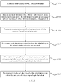
- FIG. 3 is a schematic flowchart of a firewall configuration method according to Embodiment 1 of this application.
- a compute node determines a subnet associated with received firewall policy information, and when determining that there is a virtual machine that belongs to the subnet in the compute node, delivers the firewall policy information to a network access control list that has a jump relationship with a local list of a virtual machine bridge corresponding to the virtual machine, so that the firewall policy information is deployed on a virtual machine bridge of each virtual machine.
- the firewall configuration method provided by this embodiment is applied to the cloud computing management platform shown in FIG. 2 , and the method may be performed by, for example, a proxy in a compute node.
- the firewall configuration method includes the following steps.
- the compute node determines a subnet associated with the received firewall policy information.
- a tenant may configure a preset network on a cloud computing management platform.
- the preset network includes at least one subnet, and each subnet includes at least one virtual machine. Each virtual machine may be distributed on any compute node on the cloud computing management platform.
- Different subnets are used to implement different functions, and a specific service function may be implemented through interconnection between a plurality of subnets.
- the preset network includes three subnets that are used as an interface layer, a service logic layer, and a data access layer, respectively.
- the interface layer is configured to receive an access request from a user.
- the service logic layer is configured to: determine specific service content based on the access request, and access the data access layer.
- the interface layer does not directly interact with the data access layer, but establishes a connection with the data access layer by using the service logical layer in the middle, and interacts with the data access layer by using the service logical layer.
- the cloud computing management platform receives firewall policy information entered by a tenant, and delivers the firewall policy information to each compute node included in the cloud computing management platform.
- the firewall policy information includes a subnet associated with a firewall, a firewall policy, and a rule included in the firewall policy. Because a subnet to which the virtual machine deployed on the compute node belongs may be different from the subnet associated with the firewall policy information, when receiving the firewall policy information, the compute node needs to determine the subnet associated with the firewall policy information.
- a manner in which the cloud computing management platform receives the firewall policy information may be specifically as follows:
- the cloud computing management platform receives the firewall policy information entered by the tenant in a command line interface or a web user interface. For example, after receiving the firewall policy information entered by the tenant, the cloud computing management platform checks validity of a parameter in the firewall policy information, and deletes invalid policy information from the firewall policy information.
- the firewall configuration method further includes the following step: S300.
- the compute node receives the firewall policy information.
- the firewall configuration method further includes the following step: S3001.
- the compute node determines that a firewall in the firewall policy information is associated with the subnet, and that an ingress or egress policy in the firewall policy information includes at least one rule.
- the compute node after receiving the firewall policy information, the compute node needs to determine specific content included in the firewall policy information. For example, the compute node needs to determine whether the firewall in the firewall policy information is associated with the subnet. When the firewall in the firewall policy information is not associated with the subnet, the compute node cannot determine the subnet associated with the firewall policy information, and therefore cannot determine a specific subnet to which the firewall policy information is delivered. When determining that the firewall in the firewall policy information is associated with the subnet, the compute node further determines whether the ingress or egress policy of the firewall includes at least one rule. When the ingress or egress policy of the firewall does not include a rule, the firewall is not activated. In this case, the compute node stops delivering the firewall policy information.
- the compute node determines that a virtual machine that belongs to the subnet is deployed on the compute node.
- the compute node needs to determine whether the virtual machine that belongs to the subnet is deployed on the compute node. Specifically, an agent in the compute node scans virtual machine ports in the compute node. Because virtual machines that belong to different subnets have different virtual machine ports, the compute node may determine, based on the virtual machine port in the compute node, whether the virtual machine that belongs to the subnet associated with the firewall policy information is deployed on the node. When no virtual machine that belongs to the subnet associated with the firewall policy information is deployed on the node, the compute node stops delivering the firewall policy information. When the virtual machine that belongs to the subnet associated with the firewall policy information is deployed on the node, the compute node continues to deliver the firewall policy information.
- the compute node delivers the firewall policy information to a network access control list corresponding to the subnet.
- the network access control list and a local list of a virtual machine bridge of the virtual machine are in a jump relationship.
- a specific delivery manner of the compute node is that the firewall policy information is delivered to a network access control list (ACL) corresponding to the subnet.
- ACL network access control list
- the compute node is provided with a database, the database may be used to store network an access control list corresponding to each subnet, and the network access control list includes the firewall policy information.
- a virtual machine bridge corresponding to each virtual machine deployed on the compute node corresponds to a respective local list, and the local list includes a jump rule.
- the jump rule instructs, based on the subnet to which the virtual machine belongs, the virtual machine bridge to jump, when a received packet is sent, from the local list to a network access control list that corresponds to the subnet to which the virtual machine belongs and that is stored in the database. For example, local lists corresponding to virtual machine bridges that belong to a same subnet jump to a same network access control list.
- firewall policy information of the subnet needs to be changed, only the firewall policy information of the network access control list stored in the database needs to be modified.
- the firewall configuration method further includes the following steps: S3021.
- the compute node creates the network access control list corresponding to the subnet.
- the compute node Before delivering the firewall policy information, the compute node needs to determine that there is a network access control list corresponding to a subnet corresponding to the firewall policy information in the compute node. Specifically, a name of each network access control list carries an identifier of a corresponding subnet. Therefore, the compute node may determine, by scanning the name of each network access control list in the database, whether there is a network access control list corresponding to the subnet corresponding to the firewall policy information. When there is no network access control list corresponding to the subnet corresponding to the firewall policy information, the compute node creates the network access control list corresponding to the subnet corresponding to the firewall policy information.
- a Linux iptables rule when the compute node delivers the firewall policy information to the network access control list, a Linux iptables rule, an OpenVSwitch flow table, and another firewall drive may be used to deliver the firewall policy information.
- the firewall configuration method provided in this embodiment of this application is applied to a cloud computing management platform.
- the method includes: determining, by the compute node, the subnet associated with the received firewall policy information; determining, by the compute node, that the virtual machine that belongs to the subnet is deployed on the compute node; and delivering, by the compute node, the firewall policy information to the network access control list corresponding to the subnet.
- the network access control list and the local list of the virtual machine bridge of the virtual machine are in the jump relationship.
- the firewall policy information is delivered to the virtual machine bridge corresponding to each virtual machine included in the subnet, so that when the virtual machine sends the received packet by using the virtual machine bridge, both an access packet and a response packet that belong to a same flow need to pass through a firewall deployed on the virtual machine bridge, to ensure that the firewalls can implement packet access control.
- the firewall configuration method in this embodiment is applicable to a distributed routing system.
- an embodiment of this application further provides a firewall configuration method. In this embodiment, deletion of firewall policy information in a firewall configuration is used as an example for description.
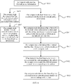
- FIG. 4 is a schematic flowchart of a firewall configuration method according to Embodiment 2 of this application. As shown in FIG. 4 , the firewall configuration method includes the following steps.
- a compute node determines that received firewall policy information is not associated with a subnet.
- the compute node determines whether the firewall policy information is associated with the subnet.
- a current firewall configuration process is to newly add or update the firewall policy information, and S301 to S303 in the embodiment shown in FIG. 3 may be performed.
- the current firewall configuration process is to delete the firewall policy information.
- the compute node deletes, from all network access control lists in the compute node, a rule that is the same as a rule included in the firewall policy information.
- the compute node determines that the firewall policy information is not associated with the subnet, the compute node checks all network access control lists stored in a database. When the rule included in the network access control list is the same as the rule included in the firewall policy information, the compute node deletes the same rule.
- the firewall configuration method provided in this embodiment includes: determining, by the compute node, that the received firewall policy information is not associated with the subnet; and deleting, by the compute node from all the network access control lists in the compute node, the rule that is the same as the rule included in the firewall policy information.
- the firewall policy information is deleted, so that excessive information interaction in a deletion process of the firewall policy information is avoided, and the deletion process of the firewall policy information is simplified.
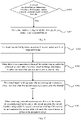
- FIG. 5 is a schematic flowchart of a packet sending method according to Embodiment 1 of this application. As shown in FIG. 5 , the packet sending method includes the following steps.
- a virtual machine bridge receives a first request packet sent by a virtual machine corresponding to the virtual machine bridge.
- the virtual machine when the virtual machine sends the first request packet to another virtual machine or an external network, the virtual machine sends the first request packet to a corresponding virtual machine bridge.
- a firewall is deployed in the virtual machine bridge.
- the virtual machine bridge determines whether the first request packet matches a firewall rule.
- the virtual machine bridge determines whether there is connection tracking of the first request packet in the firewall session table. For example, the virtual machine bridge determines, based on a 5-tuple of the first request packet, whether there is connection tracking of the first request packet in the firewall session table. When there is connection tracking of the first request packet in the firewall session table, the virtual machine bridge forwards the first request packet. When there is no connection tracking of the first request packet in the firewall session table, the virtual machine bridge determines whether the first request packet matches the firewall rule.
- the firewall rule is a network access control list configured for a user.
- the virtual machine bridge sends the first request packet to an integrated bridge when the first request packet matches the firewall rule.
- the virtual machine bridge sends the first request packet to the integrated bridge when the first request packet matches the firewall rule.
- the first request packet may be directly discarded.
- the virtual machine bridge When receiving a first response packet that is of the first request packet and that is sent by the integrated bridge, the virtual machine bridge adds first connection tracking of the first request packet to the firewall session table, and sends the first response packet to the virtual machine.
- the virtual machine bridge may add the first connection tracking of the first request packet to the firewall session table, and sends the first response packet to the virtual machine. Therefore, a request packet and a response packet that belong to a same flow as the first request packet may pass through the firewall. If the virtual machine bridge does not receive the first response packet of the first request packet within a preset time, the first request packet is discarded, and connection tracking cannot be established. Therefore, connection tracking cannot be established for a packet that does not match the firewall rule.
- the firewall is deployed in the virtual machine bridge, to ensure that the firewall can receive a request packet and a response packet that belong to a same flow, and that tracking connection can be established. Therefore, it is ensured that the firewall works normally in a distributed network architecture.
- an embodiment of this application further provides a packet sending method.
- a virtual machine bridge in addition to determining whether a first request packet matches a firewall rule, a virtual machine bridge further determines whether the first request packet matches a preset access control list rule.
- FIG. 6 is a schematic flowchart of a packet sending method according to Embodiment 2 of this application. As shown in FIG. 6 , the packet sending method further includes the following steps.
- a virtual machine bridge determines whether a first request packet matches a preset access control list rule. If the first request packet matches the preset access control list rule, S602 is performed.
- the virtual machine bridge sends the first request packet to an integrated bridge. For example, when receiving a first request packet sent by a virtual machine, the virtual machine bridge may first perform S601 to determine whether the first request packet matches the preset access control list rule. When the first request packet matches the preset access control list rule, S602 is performed to send the first request packet to the integrated bridge. When the first request packet does not match the preset access control list rule, S502 in the foregoing embodiment is performed.
- the virtual machine bridge may first perform S502 to determine whether the first request packet matches a firewall rule.
- S503 and S504 are performed.
- S601 may be performed.
- the first request packet may be discarded.
- the preset access control list rule includes at least one of the following:
- the first request packet is in a subnet to which the virtual machine belongs; or the first request packet is used to access a cloud-init service or an intrusion detection system IDS service; the first request packet is a broadcast packet; or the first request packet is a multicast packet.
- the virtual machine bridge when determining that the first request packet is in the subnet, is the broadcast packet, is the multicast packet, or is used to access the cloud-init service or the intrusion detection system IDS service, the virtual machine bridge sends the first request packet to the integrated bridge.
- the virtual machine bridge further determines whether the first request packet matches the preset access control list rule. When the first request packet matches the preset access control list rule, the virtual machine bridge directly sends the first request packet to the integrated bridge. This improves a packet sending rate.
- a working principle of a firewall deployed in the virtual machine bridge is similar to a working principle of the virtual machine externally sending the request packet. This application is described in detail with reference to the following embodiments.
- FIG. 7 is a schematic flowchart of a packet sending method according to Embodiment 3 of this application. As shown in FIG. 7 , the method includes the following steps.
- the virtual machine bridge receives a second request packet sent by an integrated bridge.
- the virtual machine bridge determines whether the second request packet matches a firewall rule.
- the virtual machine bridge determines whether there is connection tracking of the second request packet in the firewall session table. For example, the virtual machine bridge determines, based on a 5-tuple of the second request packet, whether there is connection tracking of the second request packet in the firewall session table. When there is connection tracking of the second request packet in the firewall session table, the virtual machine bridge sends the second request packet to the virtual machine. When there is no connection tracking of the second request packet in the firewall session table, the virtual machine bridge determines whether the second request packet matches the firewall rule.
- the virtual machine bridge sends the second request packet to the virtual machine when the second request packet matches the firewall rule.
- the second request packet matches the firewall rule
- the second request packet is sent to the virtual machine.
- the second request packet does not match the firewall rule, the second request packet may be directly discarded.
- the virtual machine bridge When receiving a second response packet that is of the second request packet and that is sent by the virtual machine, the virtual machine bridge adds the second connection tracking of the second request packet to the session table, and sends the second response packet to the integrated bridge.
- the virtual machine bridge may add the second connection tracking of the second request packet to the firewall session table, and forward the second response packet. Therefore, a request packet and a response packet that belong to a same flow as the second request packet may pass through a firewall. If the virtual machine bridge does not receive the second response packet of the second request packet within a preset time, the second request packet is discarded, and connection tracking cannot be established, to prevent the request packet that does not match the firewall rule from being sent to the virtual machine.
- the firewall is deployed on the virtual machine bridge, to ensure that a firewall can receive a request packet and a response packet that belong to a same flow, and that tracking connection can be established. Therefore, it is ensured that the firewall works normally in a distributed network architecture.
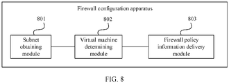
- FIG. 8 is a schematic structural diagram of a firewall configuration apparatus according to Embodiment 1 of this application.
- the apparatus is deployed on a compute node, may be the agent in the embodiment shown in FIG. 2 , and is configured to implement the firewall configuration method in the embodiment shown in FIG. 3 or FIG. 4 .
- the firewall configuration apparatus includes:
- the network access control list and a local list of a virtual machine bridge of the virtual machine are in a jump relationship.
- FIG. 9 is a schematic structural diagram of a firewall configuration apparatus according to Embodiment 2 of this application.
- the firewall configuration apparatus further includes: a network access control list creation module 804, configured to: when determining that there is no network access control list corresponding to the subnet, create the network access control list corresponding to the subnet.
- the firewall configuration apparatus further includes:
- the firewall configuration apparatus further includes: a firewall policy information check module 807, configured to determine that a firewall in the firewall policy information is associated with the subnet, and that an ingress or egress policy in the firewall policy information includes at least one rule.
- a firewall policy information check module 807 configured to determine that a firewall in the firewall policy information is associated with the subnet, and that an ingress or egress policy in the firewall policy information includes at least one rule.
- FIG. 10 is a schematic structural diagram of a packet sending apparatus according to Embodiment 1 of this application.
- the apparatus is deployed on a virtual machine bridge, and the virtual machine bridge is deployed on a compute node to which a corresponding virtual machine belongs.
- the apparatus may be the virtual machine bridge in the embodiment shown in FIG. 2 , and is configured to implement the packet sending method in the embodiments shown in FIG. 5 to FIG. 7 .
- the packet sending apparatus includes:
- the matching module 1002 is further configured to determine whether the first request packet matches a preset access control list rule.
- the sending module 1003 is further configured to: when the matching module 1002 determines that the first request packet matches the preset access control list rule, send the first request packet to the integrated bridge.
- the preset access control list rule includes at least one of the following:
- the receiving module 1001 is further configured to receive a second request packet sent by the integrated bridge.
- the matching module 1002 is further configured to: when there is no connection tracking of the second request packet in the firewall session table, determine whether the second request packet matches the firewall rule.
- the sending module 1003 is further configured to: when the second request packet matches the firewall rule, send the second request packet to the virtual machine.
- the firewall session table updating module 1004 is further configured to: when a second response packet that is of the second request packet and that is sent by the virtual machine is received, add second connection tracking of the second request packet to the session table, and send the second response packet to the integrated bridge.
- a firewall configuration device is further provided.
- FIG. 11 is a schematic structural diagram of a firewall configuration device according to Embodiment 1 of this application. As shown in FIG. 11 , the firewall configuration device includes a processor 1101, a memory 1102, a communications interface 1103, and a bus 1104.
- the processor 1101, the memory 1102, and the communications interface 1103 are connected by using the bus 1104 and communicate with each other.
- the memory 1102 is configured to store a computer executable instruction.
- the processor 1101 executes the computer executable instruction in the memory 1102 to perform, by using a hardware resource in the device, the steps in the firewall configuration method corresponding to FIG. 3 or FIG. 4 .
- FIG. 12 is a schematic structural diagram of a packet forwarding device according to Embodiment 1 of this application. As shown in FIG. 12 , the packet forwarding device includes a processor 1201, a memory 1202, a communications interface 1203, and a bus 1204.
- the processor 1201, the memory 1202, and the communications interface 1203 are connected by using the bus 1204 and communicate with each other.
- the memory 1202 is configured to store a computer executable instruction.
- the processor 1201 executes the computer executable instruction in the memory 1202 to perform, by using a hardware resource in the device, the steps in the packet sending methods corresponding to FIG. 5 to FIG. 7 .
- a computer-readable medium is further provided.
- the computer-readable storage medium stores an instruction.
- the computer is enabled to perform the instruction in the firewall configuration method corresponding to FIG. 3 or FIG. 4 .
- a computer-readable medium is further provided.
- the computer-readable storage medium stores an instruction.
- the computer is enabled to perform the instruction in the firewall configuration methods corresponding to FIG. 5 to FIG. 7 .
- All or some of the foregoing embodiments may be implemented by using software, hardware, firmware, or any combination thereof.
- software is used to implement the embodiments, all or some of the embodiments may be implemented in a form of a computer program product.
- the computer program product includes one or more computer instructions.
- the computer may be a general-purpose computer, a dedicated computer, a computer network, or another programmable apparatus.
- the computer instructions may be stored in a computer-readable storage medium or may be transmitted from a computer-readable storage medium to another computer-readable storage medium.
- the computer instructions may be transmitted from one website, computer, server, or data center to another website, computer, server, or data center in a wired (for example, a coaxial cable, an optical fiber, or a twisted pair) or wireless (for example, infrared, radio, or microwave) manner.
- the computer-readable storage medium may be any usable medium accessible by the computer, or a data storage device, such as a server or a data center, integrating one or more usable media.
- the usable medium may be a magnetic medium (for example, a floppy disk, a hard disk, or a magnetic tape), an optical medium (for example, an optical disc), or a non-transitory machine-readable medium such as a semiconductor medium (for example, a solid-state drive (SSD)) that can store program code.
- a magnetic medium for example, a floppy disk, a hard disk, or a magnetic tape
- an optical medium for example, an optical disc
- a non-transitory machine-readable medium such as a semiconductor medium (for example, a solid-state drive (SSD)) that can store program code.
- SSD solid-state drive
Landscapes
- Engineering & Computer Science (AREA)
- General Engineering & Computer Science (AREA)
- Signal Processing (AREA)
- Computer Networks & Wireless Communication (AREA)
- Computing Systems (AREA)
- Computer Security & Cryptography (AREA)
- Computer Hardware Design (AREA)
- Software Systems (AREA)
- Theoretical Computer Science (AREA)
- Business, Economics & Management (AREA)
- General Business, Economics & Management (AREA)
- Physics & Mathematics (AREA)
- General Physics & Mathematics (AREA)
- Data Exchanges In Wide-Area Networks (AREA)
Description
- This application relates to network technologies, and in particular, to a firewall configuration method and apparatus and a packet sending method and apparatus.
- A cloud computing management platform (Openstack) is an open source project intended to provide software for construction and management of a virtual public cloud and a virtual private cloud (VPC), and relates to various aspects such as a network, virtualization, an operating system, and a server. The virtual public cloud and the VPC are constructed based on the cloud computing management platform, to fully use a large quantity of physical resources.
- Network architectures of the virtual public cloud and the VPC usually include several subnets having different access control policies. A centralized routing manner is usually used for routing between different subnets. In the virtual network architecture in which centralized routing is used, an access control policy is usually implemented by using a firewall disposed on a router. An existing firewall is disposed in namespace of the router, and is implemented by using an iptables technology built in a linux operating system. As access traffic increases, a technology of a distributed virtual router (DVR,) starts to be increasingly used in the virtual network architecture, to overcome a problem that a network node has an insufficient processing capability in a centralized routing architecture.
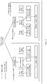
FIG. 1 is a schematic diagram of an embodiment of an existing virtual network architecture. Correspondingly, in a virtual network architecture in which distributed routing is used, a firewall is deployed in namespace of an integrated bridge. As shown inFIG. 1 , in a distributed routing technology, packets between virtual machines that are of different subnets and that are across compute nodes have different round-trip communication paths. However, according to a principle of an iptables technology, when the firewall does not receive a response packet of a request packet, the firewall discards the request packet, cannot establish connection tracking of a flow to which the request packet belongs, and cannot implement access control. Therefore, a firewall in an existing centralized routing technology is not applicable to the network architecture in which distributed virtual routing is used. -
US 2018/026944 A1 discloses techniques for assessing risk associated with firewall rules. In one implementation, a method includes receiving a request for the network to apply a firewall policy rule to control traffic to a machine associated with the network, wherein the firewall policy rule comprises information that identifies a remote address from which the traffic can originate and a type of the traffic. The method further includes determining a remote address risk value representative of a first degree of security risk associated with allowing the traffic to access the machine in response to the traffic being determined to originate from the remote address; determining a traffic type risk value representative of a second degree of security risk associated with allowing the type of traffic to access the machine; and determining a total risk value based on a combination of the remote address risk value and the traffic type risk value. The "Amazon Virtual Private Cloud" User Guide (API Version 2014-02-01) provides instructions for a user how to work with Network ACLs. -
US 2015/103839 A1 discloses a system that includes a first set of virtual machines belonging to a first overlay network and a second set of virtual machines belonging to a second overlay network. The first and second sets of virtual machines operate in several host machines, each of which includes a managed physical routing element (MPRE) for routing data packet between virtual machines in different overlay networks. A particular MPRE is configured as a bridge for routing packets between virtual machines that are in different overlay networks but in a same IP (internet protocol) subnet. - This application provides a firewall configuration method and apparatus, according to the attached claims, to resolve a problem that a firewall in an existing centralized routing technology is not applicable to a network architecture in which distributed virtual routing is used. In the following, parts of the description and drawings referring to embodiments which are not covered by the claims are not presented as embodiments of the invention, but as examples useful for understanding the invention.
- According to a first aspect of this application, a firewall configuration method is provided, and is applied to a compute node of a cloud computing management platform. The method includes:
determining, by a compute node, a subnet associated with received firewall policy information; determining, by the compute node, that a virtual machine that belongs to the subnet is deployed on the compute node; and delivering, by the compute node, the firewall policy information to a network access control list corresponding to the subnet, where the network access control list and a local list of a virtual machine bridge of the virtual machine are in a jump relationship. - The firewall policy information is delivered to a virtual machine bridge corresponding to each virtual machine included in the subnet, so that when the virtual machine sends a received packet by using the virtual machine bridge, an access packet and a response packet that belong to a same flow need to pass through a firewall deployed in the virtual machine bridge, to ensure that the firewall can implement packet access control. The firewall configuration method in this implementation is applicable to a distributed routing system.
- In a possible implementation of the first aspect, before the delivering, by the compute node, the firewall policy information to a network access control list corresponding to the subnet, when determining that there is no network access control list corresponding to the subnet, the compute node further creates the network access control list corresponding to the subnet.
- In a possible implementation of the first aspect, before the determining, by a compute node, a subnet associated with received firewall policy information, the compute node further receives the firewall policy information. The firewall configuration method further includes:
determining, by the compute node, that the received firewall policy information is not associated with the subnet; and deleting, from all network access control lists in the compute node, a rule that is the same as a rule included in the firewall policy information. - When the firewall policy information is not associated with the subnet, the firewall policy information is deleted, so that excessive information interaction in a deletion process of the firewall policy information is avoided, and the deletion process of the firewall policy information is simplified.
- In a possible implementation of the first aspect, after the receiving, by the compute node, the firewall policy information, the compute node further
determines that a firewall in the firewall policy information is associated with the subnet, and that an ingress or egress policy in the firewall policy information includes at least one rule. - According to a second aspect of this application, a packet sending method is provided. The method is applied to a virtual machine bridge, the virtual machine bridge is deployed on a compute node to which a corresponding virtual machine belongs, and the method includes:
receiving, by the virtual machine bridge, a first request packet sent by the virtual machine corresponding to the virtual machine bridge; when there is no connection tracking of the first request packet in a firewall session table, determining whether the first request packet matches a firewall rule; when the first request packet matches the firewall rule, sending the first request packet to an integrated bridge; and when receiving a first response packet that is of the first request packet and that is sent by the integrated bridge, adding first connection tracking of the first request packet to the firewall session table, and sending the first response packet to the virtual machine. - The firewall is deployed in the virtual machine bridge, to ensure that the firewall can receive both a request packet and a response packet that belong to a same flow, and that a connection tracking can be established. Therefore, it is ensured that the firewall works normally in a distributed network architecture.
- In a possible implementation of the second aspect, the virtual machine bridge further determines whether the first request packet matches a preset access control list rule. If the first request packet matches the preset access control list rule, the virtual machine bridge sends the first request packet to the integrated bridge.
- In a possible implementation of the second aspect, the preset access control list rule includes at least one of the following:
- the first request packet is in a subnet to which the virtual machine belongs;
- the first request packet is used to access a cloud-init service or an intrusion detection system IDS service;
- the first request packet is a broadcast packet; or
- the first request packet is a multicast packet.
- In a possible implementation of the second aspect, the virtual machine bridge further receives a second request packet sent by the integrated bridge; when there is no connection tracking of the second request packet in the firewall session table, determines whether the second request packet matches the firewall rule; when the second request packet matches the firewall rule, sends the second request packet to the virtual machine; and when receiving a second response packet that is of the second request packet and that is sent by the virtual machine, adds second connection tracking of the second request packet to the session table, and sends the second response packet to the integrated bridge.
- According to a third aspect of this application, a firewall configuration apparatus is provided. The apparatus is configured to perform the method in the first aspect or any possible implementation of the first aspect. Specifically, the apparatus includes a module configured to perform the method according to the first aspect or any possible implementation of the first aspect.
- In a possible implementation of the third aspect, the firewall configuration apparatus is deployed on a compute node, and the apparatus includes:
- a subnet obtaining module, configured to determine a subnet associated with received firewall policy information;
- a virtual machine determining module, configured to determine that a virtual machine that belongs to the subnet is deployed on the compute node; and
- a firewall policy information delivery module, configured to deliver the firewall policy information to a network access control list corresponding to the subnet.
- The network access control list and a local list of a virtual machine bridge of the virtual machine are in a jump relationship.
- In a first possible implementation of the third aspect, the apparatus further includes:
a network access control list creation module, configured to: when determining that there is no network access control list corresponding to the subnet, create the network access control list corresponding to the subnet. - In a first possible implementation of the third aspect, the apparatus further includes:
- a receiving module, configured to receive the firewall policy information; and
- a deletion module, configured to: when the subnet obtaining module determines that the received firewall policy information is not associated with the subnet, delete, from all network access control lists in the compute node, a rule that is the same as a rule included in the firewall policy information.
- In a first possible implementation of the third aspect, the apparatus further includes:
a firewall policy information check module, configured to determine that a firewall in the firewall policy information is associated with the subnet, and that an ingress or egress policy in the firewall policy information includes at least one rule. - According to a fourth aspect of this application, a packet sending apparatus is provided. The apparatus is configured to perform the method according to the second aspect or any possible implementation of the second aspect. Specifically, the apparatus includes a module configured to perform the method according to the second aspect or any possible implementation of the second aspect.
- In a possible implementation of the fourth aspect, the packet sending apparatus is deployed in a virtual machine bridge, the virtual machine bridge is deployed on a compute node to which a corresponding virtual machine belongs, and the apparatus includes:
- a receiving module, configured to receive a first request packet sent by the virtual machine corresponding to the virtual machine bridge;
- a matching module, configured to: when there is no connection tracking of the first request packet in a firewall session table, determine whether the first request packet matches a firewall rule;
- a sending module, configured to: when the first request packet matches the firewall rule, send the first request packet to an integrated bridge; and a firewall session table updating module, configured to: when receiving a first response packet that is of the first request packet and that is sent by the integrated bridge, add first connection tracking of the first request packet to the firewall session table, and send the first response packet to the virtual machine.
- In a possible implementation of the fourth aspect, the matching module is further configured to determine whether the first request packet matches a preset access control list rule.
- The sending module is further configured to: when the matching module determines that the first request packet matches the preset access control list rule, send the first request packet to the integrated bridge.
- In a possible implementation of the fourth aspect, the preset access control list rule includes at least one of the following:
- the first request packet is in a subnet to which the virtual machine belongs; the first request packet is used to access a cloud-init service or an intrusion detection system IDS service;
- the first request packet is a broadcast packet; or
- the first request packet is a multicast packet.
- In a possible implementation of the fourth aspect, the receiving module is further configured to receive a second request packet sent by the integrated bridge.
- The matching module is further configured to: when there is no connection tracking of the second request packet in the firewall session table, determine whether the second request packet matches the firewall rule.
- The sending module is further configured to: when the second request packet matches the firewall rule, send the second request packet to the virtual machine.
- The firewall session table updating module is further configured to: when a second response packet that is of the second request packet and that is sent by the virtual machine is received, add second connection tracking of the second request packet to the session table, and send the second response packet to the integrated bridge. According to a fifth aspect of this application, a firewall configuration device is provided, and includes a processor, a memory, a communications interface, and a bus. The processor, the memory, and the communications interface are connected by using the bus and communicate with each other. The memory is configured to store a computer executable instruction. When the device is run, the processor executes the computer executable instruction in the memory, to perform, by using a hardware resource in the device, the operation steps in the first aspect or any possible implementation of the first aspect.
- According to a sixth aspect of this application, a packet sending device is provided, and includes a processor, a memory, a communications interface, and a bus. The processor, the memory, and the communications interface are connected by using the bus and communicate with each other. The memory is configured to store a computer executable instruction. When the device is run, the processor executes the computer executable instruction in the memory to perform, by using a hardware resource in the device, the operation steps in the second aspect or any possible implementation of the second aspect.
- According to a seventh aspect of this application, a computer-readable storage medium is provided. The computer-readable storage medium stores an instruction. When the instruction is run on a computer, the computer is enabled to perform the instruction in the method according to the first aspect or any possible implementation of the first aspect.
- According to an eighth aspect of this application, a computer-readable medium is provided. The computer-readable storage medium stores an instruction. When the instruction is run on a computer, the computer is enabled to perform the instruction in the method according to the second aspect or any possible implementation of the second aspect.
- Based on the implementations provided in the foregoing aspects, the implementations may be further combined in this application to provide more implementations.
-
-
FIG. 1 is a schematic diagram of an embodiment of an existing virtual network architecture; -
FIG. 2 is a schematic architectural diagram of a cloud computing management platform to which an embodiment of this application is applicable; -
FIG. 3 is a schematic flowchart of a firewall configuration method according toEmbodiment 1 of this application; -
FIG. 4 is a schematic flowchart of a firewall configuration method according toEmbodiment 2 of this application; -
FIG. 5 is a schematic flowchart of a packet sending method according toEmbodiment 1 of this application; -
FIG. 6 is a schematic flowchart of a packet sending method according toEmbodiment 2 of this application; -
FIG. 7 is a schematic flowchart of a packet sending method according to Embodiment 3 of this application; -
FIG. 8 is a schematic structural diagram of a firewall configuration apparatus according toEmbodiment 1 of this application; -
FIG. 9 is a schematic structural diagram of a firewall configuration apparatus according toEmbodiment 2 of this application; -
FIG. 10 is a schematic structural diagram of a packet sending apparatus according toEmbodiment 1 of this application; -
FIG. 11 is a schematic structural diagram of a firewall configuration device according toEmbodiment 1 of this application; and -
FIG. 12 is a schematic structural diagram of a packet sending device according toEmbodiment 2 of this application. - The following describes the technical solutions in the embodiments of this application with reference to the accompanying drawings in the embodiments of this application.
FIG. 2 is a schematic architectural diagram of a cloud computing management platform 100 to which an embodiment of this application is applicable. As shown inFIG. 2 , the cloud computing management platform 100 may include at least one compute node. For example, as shown inFIG. 2 , the cloud computing management platform 100 may include a first compute node 101 and a second compute node 102. Each compute node provides computing, a memory, a network, and storage resources for running an instance. In consideration of a limited management capability of a single cloud computing management platform, a plurality of cloud computing management platforms are usually combined into a cloud computing management system by using a cascading structure. The cloud computing management system has a relatively high elastic scaling capability. This facilitates large-scale deployment of a virtual public cloud and a virtual private cloud. The cloud computing management system includes a first cloud computing management platform at a cascaded layer and a second cloud computing management platform at a plurality of cascaded layers. The cloud computing management platform in this embodiment of this application may be the first cloud computing management platform or the second cloud computing management platform in the cloud computing management system. - Specifically, each compute node may include at least the following: an agent, a database, a virtual switch, and at least one virtual machine. For example, the first compute node 101 includes a first agent 103, a first database 104, a first virtual switch 105, a first virtual machine 106, a second virtual machine 107, a first virtual machine bridge 108, and a second virtual machine bridge 109. The second compute node 102 includes a second agent 110, a second database 111, a second virtual switch 112, a third virtual machine 113, a fourth virtual machine 114, a third virtual machine bridge 115, and a fourth virtual machine bridge 116. Quantities of virtual machines deployed on the compute nodes may be the same or may be different. An agent and a database are set in each compute node. The agent is configured to manage deployment of a virtual machine in the compute node, and the database is configured to store configuration information of the virtual machine in the compute node. Virtual machines deployed on different compute nodes may belong to a same subnet or different subnets, and virtual machines in a same subnet are connected to a same virtual switch. Specifically, the virtual machines are connected to the virtual switch by using respective corresponding virtual machine bridges. In
FIG. 2 , the first virtual machine 106 and the second virtual machine 107 included in the first compute node 101 belong to a same subnet, which may be referred to as a first subnet. The third virtual machine 113 and the fourth virtual machine 114 included in the second compute node 102 belong to another subnet different from the first subnet, which may be referred to as a second subnet. Optionally, the first compute node 101 may further include a virtual machine that belongs to another subnet different from the first subnet and the second subnet. Virtual machines in a same subnet have a same access control policy, and same firewall policy information may be used. A packet between the virtual machines that belong to the same subnet may be directly forwarded inside the virtual switch. - For example, when the firewall policy information is configured for the virtual machines in
FIG. 2 , if a conventional firewall configuration method for a network architecture in which centralized routing is used is still used, the firewall is deployed in namespace of an integrated bridge of the virtual switch, and an iptables technology built in a Linux operating system is used as a firewall to implement packet access control. Consequently, a problem that round-trip paths of a packet may be different, and packet access control cannot be implemented. As shown inFIG. 1 , an example of a communication path of a request packet between virtual machines that are of different subnets and that are across compute nodes is shown by solid lines inFIG. 1 : Avirtual machine 1 → a virtual machine bridge → an integrated bridge → namespace → a tunnel bridge → a switch → a tunnel bridge → an integrated bridge → a virtual machine bridge → avirtual machine 2. An example of a path of a response packet corresponding to the request packet is shown by dashed lines inFIG. 1 : Thevirtual machine 2 → the virtual machine bridge → the integrated bridge → the namespace → the tunnel bridge → the switch → the tunnel bridge → the integrated bridge → the virtual machine bridge → thevirtual machine 2. Therefore, the request packet and the response packet in a same flow do not pass through a firewall in a same namespace, and the request packets and the response packets have different paths. If the firewall cannot receive the response packet of the request packet, the firewall discards the request packet, and consequently, packet access control cannot be implemented. Therefore, a firewall configuration method in an existing centralized routing technology is not applicable to a network architecture in which distributed virtual routing is used. - To resolve the foregoing problems, the embodiments of this application provide a firewall configuration method and apparatus and a packet sending method and apparatus.
- With reference to specific embodiments, the following describes in detail the firewall configuration method and apparatus and the packet sending method and apparatus that are provided in the embodiments of this application. In the following several specific embodiments, same or similar concepts or processes may not be described repeatedly in some embodiments.
- According to an aspect of the embodiments of this application, a firewall configuration method is provided.
FIG. 3 is a schematic flowchart of a firewall configuration method according toEmbodiment 1 of this application. In this embodiment, a compute node determines a subnet associated with received firewall policy information, and when determining that there is a virtual machine that belongs to the subnet in the compute node, delivers the firewall policy information to a network access control list that has a jump relationship with a local list of a virtual machine bridge corresponding to the virtual machine, so that the firewall policy information is deployed on a virtual machine bridge of each virtual machine. As shown inFIG. 3 , the firewall configuration method provided by this embodiment is applied to the cloud computing management platform shown inFIG. 2 , and the method may be performed by, for example, a proxy in a compute node. As shown inFIG. 3 , the firewall configuration method includes the following steps. - S301. The compute node determines a subnet associated with the received firewall policy information.
- For example, a tenant may configure a preset network on a cloud computing management platform. The preset network includes at least one subnet, and each subnet includes at least one virtual machine. Each virtual machine may be distributed on any compute node on the cloud computing management platform. Different subnets are used to implement different functions, and a specific service function may be implemented through interconnection between a plurality of subnets. For example, the preset network includes three subnets that are used as an interface layer, a service logic layer, and a data access layer, respectively. The interface layer is configured to receive an access request from a user. The service logic layer is configured to: determine specific service content based on the access request, and access the data access layer. The interface layer does not directly interact with the data access layer, but establishes a connection with the data access layer by using the service logical layer in the middle, and interacts with the data access layer by using the service logical layer. There are different access control policies in the three subnets, to ensure data security.
- For example, the cloud computing management platform receives firewall policy information entered by a tenant, and delivers the firewall policy information to each compute node included in the cloud computing management platform. The firewall policy information includes a subnet associated with a firewall, a firewall policy, and a rule included in the firewall policy. Because a subnet to which the virtual machine deployed on the compute node belongs may be different from the subnet associated with the firewall policy information, when receiving the firewall policy information, the compute node needs to determine the subnet associated with the firewall policy information.
- Optionally, a manner in which the cloud computing management platform receives the firewall policy information may be specifically as follows: The cloud computing management platform receives the firewall policy information entered by the tenant in a command line interface or a web user interface. For example, after receiving the firewall policy information entered by the tenant, the cloud computing management platform checks validity of a parameter in the firewall policy information, and deletes invalid policy information from the firewall policy information.
- Optionally, before the compute node determines the subnet associated with the received firewall policy information, the firewall configuration method further includes the following step:
S300. The compute node receives the firewall policy information. - Optionally, after the compute node receives the firewall policy information, the firewall configuration method further includes the following step:
S3001. The compute node determines that a firewall in the firewall policy information is associated with the subnet, and that an ingress or egress policy in the firewall policy information includes at least one rule. - For example, after receiving the firewall policy information, the compute node needs to determine specific content included in the firewall policy information. For example, the compute node needs to determine whether the firewall in the firewall policy information is associated with the subnet. When the firewall in the firewall policy information is not associated with the subnet, the compute node cannot determine the subnet associated with the firewall policy information, and therefore cannot determine a specific subnet to which the firewall policy information is delivered. When determining that the firewall in the firewall policy information is associated with the subnet, the compute node further determines whether the ingress or egress policy of the firewall includes at least one rule. When the ingress or egress policy of the firewall does not include a rule, the firewall is not activated. In this case, the compute node stops delivering the firewall policy information.
- S302. The compute node determines that a virtual machine that belongs to the subnet is deployed on the compute node.
- For example, after determining the subnet associated with the firewall policy information, the compute node needs to determine whether the virtual machine that belongs to the subnet is deployed on the compute node. Specifically, an agent in the compute node scans virtual machine ports in the compute node. Because virtual machines that belong to different subnets have different virtual machine ports, the compute node may determine, based on the virtual machine port in the compute node, whether the virtual machine that belongs to the subnet associated with the firewall policy information is deployed on the node. When no virtual machine that belongs to the subnet associated with the firewall policy information is deployed on the node, the compute node stops delivering the firewall policy information. When the virtual machine that belongs to the subnet associated with the firewall policy information is deployed on the node, the compute node continues to deliver the firewall policy information.
- S303. The compute node delivers the firewall policy information to a network access control list corresponding to the subnet.
- The network access control list and a local list of a virtual machine bridge of the virtual machine are in a jump relationship.
- For example, when the compute node determines that the firewall policy information needs to continue to be delivered, a specific delivery manner of the compute node is that the firewall policy information is delivered to a network access control list (ACL) corresponding to the subnet. For example, the compute node is provided with a database, the database may be used to store network an access control list corresponding to each subnet, and the network access control list includes the firewall policy information. A virtual machine bridge corresponding to each virtual machine deployed on the compute node corresponds to a respective local list, and the local list includes a jump rule. The jump rule instructs, based on the subnet to which the virtual machine belongs, the virtual machine bridge to jump, when a received packet is sent, from the local list to a network access control list that corresponds to the subnet to which the virtual machine belongs and that is stored in the database. For example, local lists corresponding to virtual machine bridges that belong to a same subnet jump to a same network access control list. When firewall policy information of the subnet needs to be changed, only the firewall policy information of the network access control list stored in the database needs to be modified.
- Optionally, before the compute node delivers the firewall policy information, the firewall configuration method further includes the following steps:
S3021. When determining that there is no network access control list corresponding to the subnet, the compute node creates the network access control list corresponding to the subnet. - For example, before delivering the firewall policy information, the compute node needs to determine that there is a network access control list corresponding to a subnet corresponding to the firewall policy information in the compute node. Specifically, a name of each network access control list carries an identifier of a corresponding subnet. Therefore, the compute node may determine, by scanning the name of each network access control list in the database, whether there is a network access control list corresponding to the subnet corresponding to the firewall policy information. When there is no network access control list corresponding to the subnet corresponding to the firewall policy information, the compute node creates the network access control list corresponding to the subnet corresponding to the firewall policy information.
- Optionally, when the compute node delivers the firewall policy information to the network access control list, a Linux iptables rule, an OpenVSwitch flow table, and another firewall drive may be used to deliver the firewall policy information.
- The firewall configuration method provided in this embodiment of this application is applied to a cloud computing management platform. The method includes: determining, by the compute node, the subnet associated with the received firewall policy information; determining, by the compute node, that the virtual machine that belongs to the subnet is deployed on the compute node; and delivering, by the compute node, the firewall policy information to the network access control list corresponding to the subnet. The network access control list and the local list of the virtual machine bridge of the virtual machine are in the jump relationship. In the firewall configuration method provided in this embodiment of this application, the firewall policy information is delivered to the virtual machine bridge corresponding to each virtual machine included in the subnet, so that when the virtual machine sends the received packet by using the virtual machine bridge, both an access packet and a response packet that belong to a same flow need to pass through a firewall deployed on the virtual machine bridge, to ensure that the firewalls can implement packet access control. The firewall configuration method in this embodiment is applicable to a distributed routing system. Further, based on the embodiment shown in
FIG. 3 , an embodiment of this application further provides a firewall configuration method. In this embodiment, deletion of firewall policy information in a firewall configuration is used as an example for description.FIG. 4 is a schematic flowchart of a firewall configuration method according toEmbodiment 2 of this application. As shown inFIG. 4 , the firewall configuration method includes the following steps. - S401. A compute node determines that received firewall policy information is not associated with a subnet.
- For example, when receiving the firewall policy information, the compute node determines whether the firewall policy information is associated with the subnet. When the firewall policy information is associated with the subnet, a current firewall configuration process is to newly add or update the firewall policy information, and S301 to S303 in the embodiment shown in
FIG. 3 may be performed. When the firewall policy information is not associated with the subnet, the current firewall configuration process is to delete the firewall policy information. - S402. The compute node deletes, from all network access control lists in the compute node, a rule that is the same as a rule included in the firewall policy information.
- For example, when the compute node determines that the firewall policy information is not associated with the subnet, the compute node checks all network access control lists stored in a database. When the rule included in the network access control list is the same as the rule included in the firewall policy information, the compute node deletes the same rule.
- The firewall configuration method provided in this embodiment includes: determining, by the compute node, that the received firewall policy information is not associated with the subnet; and deleting, by the compute node from all the network access control lists in the compute node, the rule that is the same as the rule included in the firewall policy information. When the firewall policy information is not associated with the subnet, the firewall policy information is deleted, so that excessive information interaction in a deletion process of the firewall policy information is avoided, and the deletion process of the firewall policy information is simplified.
- For example, according to another aspect of the embodiments of this application, a packet sending method is further provided, and is applied to the cloud computing management platform in any one of the foregoing embodiments. This embodiment may be executed by a virtual machine bridge in the cloud computing management platform shown in
FIG. 2 .FIG. 5 is a schematic flowchart of a packet sending method according toEmbodiment 1 of this application. As shown inFIG. 5 , the packet sending method includes the following steps. - S501. A virtual machine bridge receives a first request packet sent by a virtual machine corresponding to the virtual machine bridge.
- For example, when the virtual machine sends the first request packet to another virtual machine or an external network, the virtual machine sends the first request packet to a corresponding virtual machine bridge. A firewall is deployed in the virtual machine bridge.
- S502. When there is no connection tracking of the first request packet in a firewall session table, the virtual machine bridge determines whether the first request packet matches a firewall rule.
- For example, after receiving the first request packet, the virtual machine bridge determines whether there is connection tracking of the first request packet in the firewall session table. For example, the virtual machine bridge determines, based on a 5-tuple of the first request packet, whether there is connection tracking of the first request packet in the firewall session table. When there is connection tracking of the first request packet in the firewall session table, the virtual machine bridge forwards the first request packet. When there is no connection tracking of the first request packet in the firewall session table, the virtual machine bridge determines whether the first request packet matches the firewall rule. For example, the firewall rule is a network access control list configured for a user.
- S503. The virtual machine bridge sends the first request packet to an integrated bridge when the first request packet matches the firewall rule.
- For example, the virtual machine bridge sends the first request packet to the integrated bridge when the first request packet matches the firewall rule. When the first request packet does not match the firewall rule, the first request packet may be directly discarded.
- S504. When receiving a first response packet that is of the first request packet and that is sent by the integrated bridge, the virtual machine bridge adds first connection tracking of the first request packet to the firewall session table, and sends the first response packet to the virtual machine.
- For example, when receiving the first response packet of the first request packet, the virtual machine bridge may add the first connection tracking of the first request packet to the firewall session table, and sends the first response packet to the virtual machine. Therefore, a request packet and a response packet that belong to a same flow as the first request packet may pass through the firewall. If the virtual machine bridge does not receive the first response packet of the first request packet within a preset time, the first request packet is discarded, and connection tracking cannot be established. Therefore, connection tracking cannot be established for a packet that does not match the firewall rule.
- According to the packet sending method provided in this embodiment of this application, the firewall is deployed in the virtual machine bridge, to ensure that the firewall can receive a request packet and a response packet that belong to a same flow, and that tracking connection can be established. Therefore, it is ensured that the firewall works normally in a distributed network architecture.
- Optionally, an embodiment of this application further provides a packet sending method. In this embodiment, in addition to determining whether a first request packet matches a firewall rule, a virtual machine bridge further determines whether the first request packet matches a preset access control list rule.
FIG. 6 is a schematic flowchart of a packet sending method according toEmbodiment 2 of this application. As shown inFIG. 6 , the packet sending method further includes the following steps. - S601. A virtual machine bridge determines whether a first request packet matches a preset access control list rule. If the first request packet matches the preset access control list rule, S602 is performed.
- S602. The virtual machine bridge sends the first request packet to an integrated bridge. For example, when receiving a first request packet sent by a virtual machine, the virtual machine bridge may first perform S601 to determine whether the first request packet matches the preset access control list rule. When the first request packet matches the preset access control list rule, S602 is performed to send the first request packet to the integrated bridge. When the first request packet does not match the preset access control list rule, S502 in the foregoing embodiment is performed.
- For example, when receiving the first request packet sent by the virtual machine, the virtual machine bridge may first perform S502 to determine whether the first request packet matches a firewall rule. When the first request packet matches the firewall rule, S503 and S504 are performed. When the first request packet does not match the firewall rule, S601 may be performed. In this case, when the first request packet does not match the preset access control list rule, the first request packet may be discarded.
- Optionally, the preset access control list rule includes at least one of the following: The first request packet is in a subnet to which the virtual machine belongs; or
the first request packet is used to access a cloud-init service or an intrusion detection system IDS service; the first request packet is a broadcast packet; or the first request packet is a multicast packet. - For example, when determining that the first request packet is in the subnet, is the broadcast packet, is the multicast packet, or is used to access the cloud-init service or the intrusion detection system IDS service, the virtual machine bridge sends the first request packet to the integrated bridge.
- In the packet sending method provided in this embodiment, the virtual machine bridge further determines whether the first request packet matches the preset access control list rule. When the first request packet matches the preset access control list rule, the virtual machine bridge directly sends the first request packet to the integrated bridge. This improves a packet sending rate.
- For example, referring to the embodiment shown in
FIG. 5 , when the virtual machine receives a request packet, a working principle of a firewall deployed in the virtual machine bridge is similar to a working principle of the virtual machine externally sending the request packet. This application is described in detail with reference to the following embodiments. - According to still another aspect of the embodiments of this application, a packet sending method is further provided.
FIG. 7 is a schematic flowchart of a packet sending method according to Embodiment 3 of this application. As shown inFIG. 7 , the method includes the following steps. - 5701. The virtual machine bridge receives a second request packet sent by an integrated bridge.
- S702. When there is no connection tracking of the second request packet in a firewall session table, the virtual machine bridge determines whether the second request packet matches a firewall rule.
- For example, after receiving the second request packet, the virtual machine bridge determines whether there is connection tracking of the second request packet in the firewall session table. For example, the virtual machine bridge determines, based on a 5-tuple of the second request packet, whether there is connection tracking of the second request packet in the firewall session table. When there is connection tracking of the second request packet in the firewall session table, the virtual machine bridge sends the second request packet to the virtual machine. When there is no connection tracking of the second request packet in the firewall session table, the virtual machine bridge determines whether the second request packet matches the firewall rule.
- S703. The virtual machine bridge sends the second request packet to the virtual machine when the second request packet matches the firewall rule.
- For example, when the second request packet matches the firewall rule, the second request packet is sent to the virtual machine. When the second request packet does not match the firewall rule, the second request packet may be directly discarded.
- S704. When receiving a second response packet that is of the second request packet and that is sent by the virtual machine, the virtual machine bridge adds the second connection tracking of the second request packet to the session table, and sends the second response packet to the integrated bridge.
- For example, when receiving the second response packet of the second request packet, the virtual machine bridge may add the second connection tracking of the second request packet to the firewall session table, and forward the second response packet. Therefore, a request packet and a response packet that belong to a same flow as the second request packet may pass through a firewall. If the virtual machine bridge does not receive the second response packet of the second request packet within a preset time, the second request packet is discarded, and connection tracking cannot be established, to prevent the request packet that does not match the firewall rule from being sent to the virtual machine.
- According to the packet sending method provided in this embodiment of this application, the firewall is deployed on the virtual machine bridge, to ensure that a firewall can receive a request packet and a response packet that belong to a same flow, and that tracking connection can be established. Therefore, it is ensured that the firewall works normally in a distributed network architecture.
- According to yet another aspect of the embodiments of this application, a firewall configuration apparatus is further provided.
FIG. 8 is a schematic structural diagram of a firewall configuration apparatus according toEmbodiment 1 of this application. The apparatus is deployed on a compute node, may be the agent in the embodiment shown inFIG. 2 , and is configured to implement the firewall configuration method in the embodiment shown inFIG. 3 orFIG. 4 . As shown inFIG. 8 , the firewall configuration apparatus includes: - a
subnet obtaining module 801, configured to determine a subnet associated with received firewall policy information; - a virtual
machine determining module 802, configured to determine that a virtual machine that belongs to a subnet is deployed on the compute node; and - a firewall policy
information delivery module 803, configured to deliver the firewall policy information to a network access control list corresponding to the subnet. - The network access control list and a local list of a virtual machine bridge of the virtual machine are in a jump relationship.
- For example, based on the embodiment shown in
FIG. 8 ,FIG. 9 is a schematic structural diagram of a firewall configuration apparatus according toEmbodiment 2 of this application. As shown inFIG. 9 , the firewall configuration apparatus further includes:
a network access controllist creation module 804, configured to: when determining that there is no network access control list corresponding to the subnet, create the network access control list corresponding to the subnet. - Optionally, as shown in
FIG. 9 , the firewall configuration apparatus further includes: - a
receiving module 805, configured to receive the firewall policy information; and - a
deletion module 806, configured to: when thesubnet obtaining module 801 determines that the received firewall policy information is not associated with the subnet, delete, from all network access control lists in the compute node, a rule that is the same as a rule included in the firewall policy information. - Optionally, as shown in
FIG. 9 , the firewall configuration apparatus further includes:
a firewall policyinformation check module 807, configured to determine that a firewall in the firewall policy information is associated with the subnet, and that an ingress or egress policy in the firewall policy information includes at least one rule. - According to still yet another aspect of the embodiment of this application, a packet sending apparatus is further provided.
FIG. 10 is a schematic structural diagram of a packet sending apparatus according toEmbodiment 1 of this application. The apparatus is deployed on a virtual machine bridge, and the virtual machine bridge is deployed on a compute node to which a corresponding virtual machine belongs. The apparatus may be the virtual machine bridge in the embodiment shown inFIG. 2 , and is configured to implement the packet sending method in the embodiments shown inFIG. 5 to FIG. 7 . As shown inFIG. 10 , the packet sending apparatus includes: - a
receiving module 1001, configured to receive a first request packet sent by a virtual machine corresponding to the virtual machine bridge; - a
matching module 1002, configured to: when there is no connection tracking of the first request packet in a firewall session table, determine whether the first request packet matches a firewall rule; - a
sending module 1003, configured to: when the first request packet matches the firewall rule, send the first request packet to an integrated bridge; and - a firewall session
table updating module 1004, configured to: when receiving a first response packet that is of the first request packet and that is sent by the integrated bridge, add first connection tracking of the first request packet to the firewall session table, and send the first response packet to the virtual machine. - Optionally, the
matching module 1002 is further configured to determine whether the first request packet matches a preset access control list rule. - The sending
module 1003 is further configured to: when thematching module 1002 determines that the first request packet matches the preset access control list rule, send the first request packet to the integrated bridge. - Optionally, the preset access control list rule includes at least one of the following:
- the first request packet is in a subnet to which the virtual machine belongs;
- the first request packet is used to access a cloud-init service or an intrusion detection system IDS service;
- the first request packet is a broadcast packet; or
- the first request packet is a multicast packet.
- Optionally, the
receiving module 1001 is further configured to receive a second request packet sent by the integrated bridge. - The
matching module 1002 is further configured to: when there is no connection tracking of the second request packet in the firewall session table, determine whether the second request packet matches the firewall rule. - The sending
module 1003 is further configured to: when the second request packet matches the firewall rule, send the second request packet to the virtual machine. - The firewall session
table updating module 1004 is further configured to: when a second response packet that is of the second request packet and that is sent by the virtual machine is received, add second connection tracking of the second request packet to the session table, and send the second response packet to the integrated bridge. According to a further aspect of the embodiment of this application, a firewall configuration device is further provided.FIG. 11 is a schematic structural diagram of a firewall configuration device according toEmbodiment 1 of this application. As shown inFIG. 11 , the firewall configuration device includes a processor 1101, amemory 1102, acommunications interface 1103, and abus 1104. - The processor 1101, the
memory 1102, and thecommunications interface 1103 are connected by using thebus 1104 and communicate with each other. Thememory 1102 is configured to store a computer executable instruction. When the device is run, the processor 1101 executes the computer executable instruction in thememory 1102 to perform, by using a hardware resource in the device, the steps in the firewall configuration method corresponding toFIG. 3 orFIG. 4 . - According to a still further aspect of the embodiment of this application, a packet sending device is further provided.
FIG. 12 is a schematic structural diagram of a packet forwarding device according toEmbodiment 1 of this application. As shown inFIG. 12 , the packet forwarding device includes aprocessor 1201, a memory 1202, a communications interface 1203, and abus 1204. - The
processor 1201, the memory 1202, and the communications interface 1203 are connected by using thebus 1204 and communicate with each other. The memory 1202 is configured to store a computer executable instruction. When the device is run, theprocessor 1201 executes the computer executable instruction in the memory 1202 to perform, by using a hardware resource in the device, the steps in the packet sending methods corresponding toFIG. 5 to FIG. 7 . - According to a yet further aspect of the embodiment of this application, a computer-readable medium is further provided. The computer-readable storage medium stores an instruction. When the instruction is run on a computer, the computer is enabled to perform the instruction in the firewall configuration method corresponding to
FIG. 3 orFIG. 4 . - According to a still yet further aspect of the embodiment of this application, a computer-readable medium is further provided. The computer-readable storage medium stores an instruction. When the instruction is run on a computer, the computer is enabled to perform the instruction in the firewall configuration methods corresponding to
FIG. 5 to FIG. 7 . - A person of ordinary skill in the art may be aware that in combination with the examples described in the embodiments disclosed in this specification, methods and steps may be implemented by electronic hardware or a combination of computer software and electronic hardware. Whether the functions are performed by hardware or software depends on particular applications and design constraint conditions of technical solutions. A person skilled in the art may use different methods to implement the described functions for each particular application, but it should not be considered that the implementation goes beyond the scope of this application.
- All or some of the foregoing embodiments may be implemented by using software, hardware, firmware, or any combination thereof. When software is used to implement the embodiments, all or some of the embodiments may be implemented in a form of a computer program product. The computer program product includes one or more computer instructions. When the computer program instructions are loaded and executed on a computer, the procedures or functions according to the embodiments of this application are completely or partially generated. The computer may be a general-purpose computer, a dedicated computer, a computer network, or another programmable apparatus. The computer instructions may be stored in a computer-readable storage medium or may be transmitted from a computer-readable storage medium to another computer-readable storage medium. For example, the computer instructions may be transmitted from one website, computer, server, or data center to another website, computer, server, or data center in a wired (for example, a coaxial cable, an optical fiber, or a twisted pair) or wireless (for example, infrared, radio, or microwave) manner. The computer-readable storage medium may be any usable medium accessible by the computer, or a data storage device, such as a server or a data center, integrating one or more usable media. The usable medium may be a magnetic medium (for example, a floppy disk, a hard disk, or a magnetic tape), an optical medium (for example, an optical disc), or a non-transitory machine-readable medium such as a semiconductor medium (for example, a solid-state drive (SSD)) that can store program code.
- It should be noted that the embodiments provided in this application are merely examples. A person skilled in the art may be clearly aware that for convenience and conciseness of description, in the foregoing embodiments, the embodiments emphasize different aspects, and for a part not described in detail in one embodiment, refer to related description of another embodiment. The embodiments of this application and the features disclosed in the accompanying drawings may independently exist, or may exist in a combination manner. Features described in a hardware form in the embodiments of this application may be executed by software, and vice versa. This is not limited herein.
Claims (8)
- A firewall configuration method, wherein the method comprises:determining (S301), by a compute node, a subnet associated with firewall policy information received (S300) by the compute node;determining (S302), by the compute node, that a virtual machine that belongs to the subnet is deployed on the compute node; anddelivering (S303), by the compute node, the firewall policy information to a network access control list corresponding to the subnet, whereinthe network access control list and a local list of a virtual machine bridge of the virtual machine are in a jump relationship, wherein the jump relationship means that the local list includes a jump rule,the jump rule instructs, based on the subnet to which the virtual machine belongs, the virtual machine bridge to jump, when a received packet is sent, from the local list to the network access control list.
- The method according to claim 1, wherein before the delivering (S303), by the compute node, the firewall policy information to a network access control list corresponding to the subnet, the method further comprises:
creating (S3021), by the compute node, the network access control list corresponding to the subnet when determining that there is no network access control list corresponding to the subnet. - The method according to claim 1 or 2, wherein before the determining (S301), by a compute node, a subnet associated with received firewall policy information, the method further comprises:receiving (S300), by the compute node, the firewall policy information; andthe method further comprises:determining (S401), by the compute node, that the received firewall policy information is not associated with the subnet; anddeleting (S402), by the compute node from all network access control lists in the compute node, a rule that is the same as a rule comprised in the firewall policy information.
- The method according to claim 3, wherein after the receiving (S300), by the compute node, the firewall policy information, the method further comprises:
determining (S3001), by the compute node, that a firewall in the firewall policy information is associated with the subnet, and that an ingress or egress policy in the firewall policy information comprises at least one rule. - A firewall configuration apparatus, wherein the apparatus is deployed on a compute node, and the apparatus comprises:a subnet obtaining module (801), configured to determine a subnet associated with firewall policy information received (S300) by the compute node;a virtual machine determining module (802), configured to determine that a virtual machine that belongs to the subnet is deployed on the compute node; anda firewall policy information delivery module (803), configured to deliver the firewall policy information to a network access control list corresponding to the subnet, whereinthe network access control list and a local list of a virtual machine bridge of the virtual machine are in a jump relationship, wherein the jump relationship means that the local list includes a jump rule,the jump rule is configured to instruct, based on the subnet to which the virtual machine belongs, the virtual machine bridge to jump, when a received packet is sent, from the local list to the network access control list.
- The apparatus according to claim 5, wherein the apparatus further comprises:
a network access control list creation module (804), configured to: when determining that there is no network access control list corresponding to the subnet, create the network access control list corresponding to the subnet. - The apparatus according to claim 5, wherein the apparatus further comprises:a receiving module (805), configured to receive the firewall policy information; anda deletion module (806), configured to: when the subnet obtaining module (801) determines that the received firewall policy information is not associated with the subnet, delete, from all network access control lists in the compute node, a rule that is the same as a rule comprised in the firewall policy information.
- A firewall configuration device, comprising a processor, a memory, a communications interface, and a bus, wherein the processor, the memory, and the communications interface are connected by using the bus and communicate with each other, the memory is configured to store a computer executable instruction, and when the device is run, the processor executes the computer executable instruction in the memory, to perform, by using a hardware resource in the device, the operation steps in the method according to any one of claims 1 to 4.
Applications Claiming Priority (2)
| Application Number | Priority Date | Filing Date | Title |
|---|---|---|---|
| CN201810099188.8A CN108471397B (en) | 2018-01-31 | 2018-01-31 | Firewall configuration, message sending method and device |
| PCT/CN2018/104307 WO2019148839A1 (en) | 2018-01-31 | 2018-09-06 | Firewall configuration and message sending method and device |
Publications (3)
| Publication Number | Publication Date |
|---|---|
| EP3737036A1 EP3737036A1 (en) | 2020-11-11 |
| EP3737036A4 EP3737036A4 (en) | 2021-04-14 |
| EP3737036B1 true EP3737036B1 (en) | 2023-01-18 |
Family
ID=63266315
Family Applications (1)
| Application Number | Title | Priority Date | Filing Date |
|---|---|---|---|
| EP18903293.1A Active EP3737036B1 (en) | 2018-01-31 | 2018-09-06 | Firewall configuration and message sending method and device |
Country Status (4)
| Country | Link |
|---|---|
| US (1) | US12095733B2 (en) |
| EP (1) | EP3737036B1 (en) |
| CN (1) | CN108471397B (en) |
| WO (1) | WO2019148839A1 (en) |
Families Citing this family (23)
| Publication number | Priority date | Publication date | Assignee | Title |
|---|---|---|---|---|
| CN108471397B (en) * | 2018-01-31 | 2020-12-15 | 华为技术有限公司 | Firewall configuration, message sending method and device |
| CN109040125A (en) * | 2018-09-18 | 2018-12-18 | 郑州云海信息技术有限公司 | Message filtering method and device in virtual machine |
| US11494212B2 (en) * | 2018-09-27 | 2022-11-08 | Intel Corporation | Technologies for adaptive platform resource assignment |
| CN109088886B (en) * | 2018-09-29 | 2021-10-01 | 郑州云海信息技术有限公司 | Management method and device for monitoring policy on firewall |
| CN109743326B (en) * | 2019-01-10 | 2021-09-07 | 新华三云计算技术有限公司 | Traffic transmission method and device |
| CN109617920B (en) * | 2019-01-23 | 2021-07-20 | 新华三信息安全技术有限公司 | Message processing method and device, router and firewall equipment |
| CN109962914B (en) * | 2019-03-12 | 2021-07-23 | 杭州迪普科技股份有限公司 | Firewall configuration method and device |
| CN109756520B (en) * | 2019-03-19 | 2021-05-11 | 全链通有限公司 | Dynamic access control method, device and computer-readable storage medium |
| CN110336730B (en) * | 2019-07-09 | 2022-01-18 | 腾讯科技(深圳)有限公司 | Network system and data transmission method |
| CN113709052B (en) * | 2020-05-21 | 2024-02-27 | 中移(苏州)软件技术有限公司 | A network message processing method, device, electronic equipment and storage medium |
| CN113765858A (en) * | 2020-06-05 | 2021-12-07 | 中创为(成都)量子通信技术有限公司 | Method and device for realizing high-performance state firewall |
| CN112217689B (en) * | 2020-09-11 | 2022-05-31 | 苏州浪潮智能科技有限公司 | Network message tracking method and system based on OpenStack |
| CN114679290B (en) * | 2021-05-20 | 2023-03-24 | 腾讯云计算(北京)有限责任公司 | A network security management method and electronic equipment |
| CN113595802B (en) * | 2021-08-09 | 2024-07-02 | 山石网科通信技术股份有限公司 | Upgrading method and device for distributed firewall |
| CN113612807B (en) * | 2021-10-09 | 2021-12-03 | 苏州浪潮智能科技有限公司 | Distributed firewall definition method and system |
| CN116266809A (en) * | 2021-12-16 | 2023-06-20 | 中国科学院深圳先进技术研究院 | Gateway node configuration method and system, gateway node, server cluster |
| CN116264518B (en) * | 2022-08-31 | 2026-02-24 | 中移(苏州)软件技术有限公司 | Cloud service mutual access method, system, network node and medium based on cloud private line |
| CN115622808B (en) * | 2022-12-13 | 2023-05-23 | 北京市大数据中心 | Method for secure isolation, electronic device, computer readable medium |
| CN115664870B (en) * | 2022-12-28 | 2023-04-07 | 北京志翔科技股份有限公司 | Cross-distributed-node desktop access method, device and system and electronic equipment |
| CN119172086A (en) * | 2023-06-13 | 2024-12-20 | 中兴通讯股份有限公司 | Firewall configuration method, NFVO, server and storage medium |
| CN116668164B (en) * | 2023-06-26 | 2024-01-02 | 中国电子信息产业集团有限公司第六研究所 | Industrial firewall security isolation detection and processing methods, systems and storage media |
| CN117938699A (en) * | 2023-12-13 | 2024-04-26 | 天翼云科技有限公司 | Internet surfing behavior management method and system |
| CN119382992A (en) * | 2024-11-05 | 2025-01-28 | 贵州电网有限责任公司 | A network access control method and system based on domestic server |
Family Cites Families (15)
| Publication number | Priority date | Publication date | Assignee | Title |
|---|---|---|---|---|
| CN100451974C (en) * | 2007-02-12 | 2009-01-14 | 杭州华三通信技术有限公司 | Method and apparatus for managing session table |
| JP4488077B2 (en) * | 2008-02-29 | 2010-06-23 | 日本電気株式会社 | Virtualization system, virtualization method, and virtualization program |
| US8893274B2 (en) * | 2011-08-03 | 2014-11-18 | Trend Micro, Inc. | Cross-VM network filtering |
| WO2013126442A1 (en) * | 2012-02-20 | 2013-08-29 | Virtustream Canada Holdings, Inc. | Systems involving firewall of virtual machine traffic and methods of processing information associated with same |
| US9967111B2 (en) * | 2013-03-15 | 2018-05-08 | Rackspace Us, Inc. | Software-defined multinetwork bridge |
| US9785455B2 (en) * | 2013-10-13 | 2017-10-10 | Nicira, Inc. | Logical router |
| US9860117B2 (en) * | 2014-02-03 | 2018-01-02 | Sprint Communications Company, L.P. | Automatically generated virtual network elements for virtualized packet networks |
| CN104023011B (en) * | 2014-05-30 | 2017-04-26 | 国云科技股份有限公司 | Network firewall realization method suitable for virtual machine |
| US9692727B2 (en) * | 2014-12-02 | 2017-06-27 | Nicira, Inc. | Context-aware distributed firewall |
| CN105471662B (en) * | 2015-12-30 | 2019-02-26 | 中电长城网际系统应用有限公司 | Cloud Server, virtual network strategy centralized control system and method |
| US10142163B2 (en) * | 2016-03-07 | 2018-11-27 | Cisco Technology, Inc | BFD over VxLAN on vPC uplinks |
| CN107517119B (en) * | 2016-06-17 | 2021-02-26 | 阿里巴巴集团控股有限公司 | Virtual network detection method and device in VPC environment |
| US10237240B2 (en) * | 2016-07-21 | 2019-03-19 | AT&T Global Network Services (U.K.) B.V. | Assessing risk associated with firewall rules |
| CN106453333B (en) * | 2016-10-19 | 2019-08-30 | 深信服科技股份有限公司 | The firewall rule creation method and device of virtual platform |
| CN108471397B (en) * | 2018-01-31 | 2020-12-15 | 华为技术有限公司 | Firewall configuration, message sending method and device |
-
2018
- 2018-01-31 CN CN201810099188.8A patent/CN108471397B/en active Active
- 2018-09-06 WO PCT/CN2018/104307 patent/WO2019148839A1/en not_active Ceased
- 2018-09-06 EP EP18903293.1A patent/EP3737036B1/en active Active
-
2020
- 2020-07-30 US US16/943,264 patent/US12095733B2/en active Active
Also Published As
| Publication number | Publication date |
|---|---|
| WO2019148839A1 (en) | 2019-08-08 |
| EP3737036A1 (en) | 2020-11-11 |
| US20200358745A1 (en) | 2020-11-12 |
| EP3737036A4 (en) | 2021-04-14 |
| CN108471397A (en) | 2018-08-31 |
| CN108471397B (en) | 2020-12-15 |
| US12095733B2 (en) | 2024-09-17 |
Similar Documents
| Publication | Publication Date | Title |
|---|---|---|
| US12095733B2 (en) | Firewall configuration method and apparatus and packet sending method and apparatus | |
| US20220239701A1 (en) | Control access to domains, servers, and content | |
| CN110120934B (en) | Method of applying firewall policy, software-defined network controller and media | |
| EP2806601B1 (en) | Tunnels between virtual machines | |
| EP3883217A1 (en) | Data transmission method and computer system | |
| CN114978567B (en) | A method for topology discovery | |
| US10608841B2 (en) | Autonomous system bridge connecting in a telecommunications network | |
| CN105227541A (en) | A kind of security strategy dynamic migration method and device | |
| WO2023056722A1 (en) | Distributed firewall definition method and system | |
| US7730294B2 (en) | System for geographically distributed virtual routing | |
| CN112671811B (en) | Network access method and equipment | |
| CN106357443B (en) | A kind of method and apparatus of network configuration | |
| US12563057B2 (en) | Method and a system for traffic tunneling in a distributed network for malware detection | |
| CN112968879A (en) | A method and device for implementing firewall management | |
| US10257087B2 (en) | Communication device and communication method | |
| CN111884863A (en) | VPC service chain implementation method and system for cloud computing environment | |
| CN109417513B (en) | System and method for dynamically detecting opposite terminal in software defined network | |
| CN112994928A (en) | Virtual machine management method, device and system | |
| CN118842726A (en) | Message transmission method, device and system | |
| US12432555B2 (en) | Multi AP microbranch deployment configuration based on optimized packet forwarding | |
| CN113098856B (en) | Implementation method and security device of a virtual private network VPN in a transparent mode | |
| KR102136923B1 (en) | System and method for providing security service of road traffic network using software defined networking and network function virtualization | |
| Carthern et al. | Data Center and NX-OS | |
| CN117222995A (en) | Systems and methods for restricting communications between virtual private cloud networks through security domains | |
| CN116980196A (en) | Safety protection method and device and electronic equipment |
Legal Events
| Date | Code | Title | Description |
|---|---|---|---|
| STAA | Information on the status of an ep patent application or granted ep patent |
Free format text: STATUS: THE INTERNATIONAL PUBLICATION HAS BEEN MADE |
|
| PUAI | Public reference made under article 153(3) epc to a published international application that has entered the european phase |
Free format text: ORIGINAL CODE: 0009012 |
|
| STAA | Information on the status of an ep patent application or granted ep patent |
Free format text: STATUS: REQUEST FOR EXAMINATION WAS MADE |
|
| 17P | Request for examination filed |
Effective date: 20200807 |
|
| AK | Designated contracting states |
Kind code of ref document: A1 Designated state(s): AL AT BE BG CH CY CZ DE DK EE ES FI FR GB GR HR HU IE IS IT LI LT LU LV MC MK MT NL NO PL PT RO RS SE SI SK SM TR |
|
| AX | Request for extension of the european patent |
Extension state: BA ME |
|
| RIC1 | Information provided on ipc code assigned before grant |
Ipc: H04L 12/46 20060101ALI20201207BHEP Ipc: H04L 29/06 20060101ALI20201207BHEP Ipc: H04L 12/22 20060101AFI20201207BHEP |
|
| A4 | Supplementary search report drawn up and despatched |
Effective date: 20210315 |
|
| RIC1 | Information provided on ipc code assigned before grant |
Ipc: H04L 12/22 20060101AFI20210309BHEP Ipc: H04L 12/46 20060101ALI20210309BHEP Ipc: H04L 29/06 20060101ALI20210309BHEP |
|
| DAV | Request for validation of the european patent (deleted) | ||
| DAX | Request for extension of the european patent (deleted) | ||
| RAP1 | Party data changed (applicant data changed or rights of an application transferred) |
Owner name: HUAWEI CLOUD COMPUTING TECHNOLOGIES CO., LTD. |
|
| REG | Reference to a national code |
Ref country code: DE Ref legal event code: R079 Ref document number: 602018045628 Country of ref document: DE Free format text: PREVIOUS MAIN CLASS: H04L0012220000 Ipc: H04L0009400000 |
|
| GRAP | Despatch of communication of intention to grant a patent |
Free format text: ORIGINAL CODE: EPIDOSNIGR1 |
|
| STAA | Information on the status of an ep patent application or granted ep patent |
Free format text: STATUS: GRANT OF PATENT IS INTENDED |
|
| RIC1 | Information provided on ipc code assigned before grant |
Ipc: H04L 12/22 20060101ALI20220629BHEP Ipc: H04L 12/46 20060101ALI20220629BHEP Ipc: H04L 9/40 20220101AFI20220629BHEP |
|
| INTG | Intention to grant announced |
Effective date: 20220803 |
|
| GRAS | Grant fee paid |
Free format text: ORIGINAL CODE: EPIDOSNIGR3 |
|
| GRAA | (expected) grant |
Free format text: ORIGINAL CODE: 0009210 |
|
| STAA | Information on the status of an ep patent application or granted ep patent |
Free format text: STATUS: THE PATENT HAS BEEN GRANTED |
|
| AK | Designated contracting states |
Kind code of ref document: B1 Designated state(s): AL AT BE BG CH CY CZ DE DK EE ES FI FR GB GR HR HU IE IS IT LI LT LU LV MC MK MT NL NO PL PT RO RS SE SI SK SM TR |
|
| REG | Reference to a national code |
Ref country code: GB Ref legal event code: FG4D |
|
| REG | Reference to a national code |
Ref country code: CH Ref legal event code: EP |
|
| REG | Reference to a national code |
Ref country code: DE Ref legal event code: R096 Ref document number: 602018045628 Country of ref document: DE |
|
| REG | Reference to a national code |
Ref country code: AT Ref legal event code: REF Ref document number: 1545260 Country of ref document: AT Kind code of ref document: T Effective date: 20230215 Ref country code: IE Ref legal event code: FG4D |
|
| REG | Reference to a national code |
Ref country code: LT Ref legal event code: MG9D |
|
| REG | Reference to a national code |
Ref country code: NL Ref legal event code: MP Effective date: 20230118 |
|
| REG | Reference to a national code |
Ref country code: AT Ref legal event code: MK05 Ref document number: 1545260 Country of ref document: AT Kind code of ref document: T Effective date: 20230118 |
|
| P01 | Opt-out of the competence of the unified patent court (upc) registered |
Effective date: 20230524 |
|
| PG25 | Lapsed in a contracting state [announced via postgrant information from national office to epo] |
Ref country code: NL Free format text: LAPSE BECAUSE OF FAILURE TO SUBMIT A TRANSLATION OF THE DESCRIPTION OR TO PAY THE FEE WITHIN THE PRESCRIBED TIME-LIMIT Effective date: 20230118 |
|
| PG25 | Lapsed in a contracting state [announced via postgrant information from national office to epo] |
Ref country code: RS Free format text: LAPSE BECAUSE OF FAILURE TO SUBMIT A TRANSLATION OF THE DESCRIPTION OR TO PAY THE FEE WITHIN THE PRESCRIBED TIME-LIMIT Effective date: 20230118 Ref country code: PT Free format text: LAPSE BECAUSE OF FAILURE TO SUBMIT A TRANSLATION OF THE DESCRIPTION OR TO PAY THE FEE WITHIN THE PRESCRIBED TIME-LIMIT Effective date: 20230518 Ref country code: NO Free format text: LAPSE BECAUSE OF FAILURE TO SUBMIT A TRANSLATION OF THE DESCRIPTION OR TO PAY THE FEE WITHIN THE PRESCRIBED TIME-LIMIT Effective date: 20230418 Ref country code: LV Free format text: LAPSE BECAUSE OF FAILURE TO SUBMIT A TRANSLATION OF THE DESCRIPTION OR TO PAY THE FEE WITHIN THE PRESCRIBED TIME-LIMIT Effective date: 20230118 Ref country code: LT Free format text: LAPSE BECAUSE OF FAILURE TO SUBMIT A TRANSLATION OF THE DESCRIPTION OR TO PAY THE FEE WITHIN THE PRESCRIBED TIME-LIMIT Effective date: 20230118 Ref country code: HR Free format text: LAPSE BECAUSE OF FAILURE TO SUBMIT A TRANSLATION OF THE DESCRIPTION OR TO PAY THE FEE WITHIN THE PRESCRIBED TIME-LIMIT Effective date: 20230118 Ref country code: ES Free format text: LAPSE BECAUSE OF FAILURE TO SUBMIT A TRANSLATION OF THE DESCRIPTION OR TO PAY THE FEE WITHIN THE PRESCRIBED TIME-LIMIT Effective date: 20230118 Ref country code: AT Free format text: LAPSE BECAUSE OF FAILURE TO SUBMIT A TRANSLATION OF THE DESCRIPTION OR TO PAY THE FEE WITHIN THE PRESCRIBED TIME-LIMIT Effective date: 20230118 |
|
| PG25 | Lapsed in a contracting state [announced via postgrant information from national office to epo] |
Ref country code: SE Free format text: LAPSE BECAUSE OF FAILURE TO SUBMIT A TRANSLATION OF THE DESCRIPTION OR TO PAY THE FEE WITHIN THE PRESCRIBED TIME-LIMIT Effective date: 20230118 Ref country code: PL Free format text: LAPSE BECAUSE OF FAILURE TO SUBMIT A TRANSLATION OF THE DESCRIPTION OR TO PAY THE FEE WITHIN THE PRESCRIBED TIME-LIMIT Effective date: 20230118 Ref country code: IS Free format text: LAPSE BECAUSE OF FAILURE TO SUBMIT A TRANSLATION OF THE DESCRIPTION OR TO PAY THE FEE WITHIN THE PRESCRIBED TIME-LIMIT Effective date: 20230518 Ref country code: GR Free format text: LAPSE BECAUSE OF FAILURE TO SUBMIT A TRANSLATION OF THE DESCRIPTION OR TO PAY THE FEE WITHIN THE PRESCRIBED TIME-LIMIT Effective date: 20230419 Ref country code: FI Free format text: LAPSE BECAUSE OF FAILURE TO SUBMIT A TRANSLATION OF THE DESCRIPTION OR TO PAY THE FEE WITHIN THE PRESCRIBED TIME-LIMIT Effective date: 20230118 |
|
| REG | Reference to a national code |
Ref country code: DE Ref legal event code: R097 Ref document number: 602018045628 Country of ref document: DE |
|
| PG25 | Lapsed in a contracting state [announced via postgrant information from national office to epo] |
Ref country code: SM Free format text: LAPSE BECAUSE OF FAILURE TO SUBMIT A TRANSLATION OF THE DESCRIPTION OR TO PAY THE FEE WITHIN THE PRESCRIBED TIME-LIMIT Effective date: 20230118 Ref country code: RO Free format text: LAPSE BECAUSE OF FAILURE TO SUBMIT A TRANSLATION OF THE DESCRIPTION OR TO PAY THE FEE WITHIN THE PRESCRIBED TIME-LIMIT Effective date: 20230118 Ref country code: EE Free format text: LAPSE BECAUSE OF FAILURE TO SUBMIT A TRANSLATION OF THE DESCRIPTION OR TO PAY THE FEE WITHIN THE PRESCRIBED TIME-LIMIT Effective date: 20230118 Ref country code: DK Free format text: LAPSE BECAUSE OF FAILURE TO SUBMIT A TRANSLATION OF THE DESCRIPTION OR TO PAY THE FEE WITHIN THE PRESCRIBED TIME-LIMIT Effective date: 20230118 Ref country code: CZ Free format text: LAPSE BECAUSE OF FAILURE TO SUBMIT A TRANSLATION OF THE DESCRIPTION OR TO PAY THE FEE WITHIN THE PRESCRIBED TIME-LIMIT Effective date: 20230118 |
|
| PLBE | No opposition filed within time limit |
Free format text: ORIGINAL CODE: 0009261 |
|
| STAA | Information on the status of an ep patent application or granted ep patent |
Free format text: STATUS: NO OPPOSITION FILED WITHIN TIME LIMIT |
|
| PG25 | Lapsed in a contracting state [announced via postgrant information from national office to epo] |
Ref country code: SK Free format text: LAPSE BECAUSE OF FAILURE TO SUBMIT A TRANSLATION OF THE DESCRIPTION OR TO PAY THE FEE WITHIN THE PRESCRIBED TIME-LIMIT Effective date: 20230118 |
|
| 26N | No opposition filed |
Effective date: 20231019 |
|
| PG25 | Lapsed in a contracting state [announced via postgrant information from national office to epo] |
Ref country code: SI Free format text: LAPSE BECAUSE OF FAILURE TO SUBMIT A TRANSLATION OF THE DESCRIPTION OR TO PAY THE FEE WITHIN THE PRESCRIBED TIME-LIMIT Effective date: 20230118 |
|
| REG | Reference to a national code |
Ref country code: CH Ref legal event code: PL |
|
| PG25 | Lapsed in a contracting state [announced via postgrant information from national office to epo] |
Ref country code: LU Free format text: LAPSE BECAUSE OF NON-PAYMENT OF DUE FEES Effective date: 20230906 |
|
| REG | Reference to a national code |
Ref country code: BE Ref legal event code: MM Effective date: 20230930 |
|
| PG25 | Lapsed in a contracting state [announced via postgrant information from national office to epo] |
Ref country code: LU Free format text: LAPSE BECAUSE OF NON-PAYMENT OF DUE FEES Effective date: 20230906 Ref country code: IT Free format text: LAPSE BECAUSE OF FAILURE TO SUBMIT A TRANSLATION OF THE DESCRIPTION OR TO PAY THE FEE WITHIN THE PRESCRIBED TIME-LIMIT Effective date: 20230118 Ref country code: MC Free format text: LAPSE BECAUSE OF FAILURE TO SUBMIT A TRANSLATION OF THE DESCRIPTION OR TO PAY THE FEE WITHIN THE PRESCRIBED TIME-LIMIT Effective date: 20230118 |
|
| REG | Reference to a national code |
Ref country code: IE Ref legal event code: MM4A |
|
| PG25 | Lapsed in a contracting state [announced via postgrant information from national office to epo] |
Ref country code: IE Free format text: LAPSE BECAUSE OF NON-PAYMENT OF DUE FEES Effective date: 20230906 |
|
| PG25 | Lapsed in a contracting state [announced via postgrant information from national office to epo] |
Ref country code: CH Free format text: LAPSE BECAUSE OF NON-PAYMENT OF DUE FEES Effective date: 20230930 |
|
| PG25 | Lapsed in a contracting state [announced via postgrant information from national office to epo] |
Ref country code: IE Free format text: LAPSE BECAUSE OF NON-PAYMENT OF DUE FEES Effective date: 20230906 Ref country code: CH Free format text: LAPSE BECAUSE OF NON-PAYMENT OF DUE FEES Effective date: 20230930 |
|
| PG25 | Lapsed in a contracting state [announced via postgrant information from national office to epo] |
Ref country code: BE Free format text: LAPSE BECAUSE OF NON-PAYMENT OF DUE FEES Effective date: 20230930 |
|
| PG25 | Lapsed in a contracting state [announced via postgrant information from national office to epo] |
Ref country code: BG Free format text: LAPSE BECAUSE OF FAILURE TO SUBMIT A TRANSLATION OF THE DESCRIPTION OR TO PAY THE FEE WITHIN THE PRESCRIBED TIME-LIMIT Effective date: 20230118 |
|
| PG25 | Lapsed in a contracting state [announced via postgrant information from national office to epo] |
Ref country code: BG Free format text: LAPSE BECAUSE OF FAILURE TO SUBMIT A TRANSLATION OF THE DESCRIPTION OR TO PAY THE FEE WITHIN THE PRESCRIBED TIME-LIMIT Effective date: 20230118 |
|
| PG25 | Lapsed in a contracting state [announced via postgrant information from national office to epo] |
Ref country code: CY Free format text: LAPSE BECAUSE OF FAILURE TO SUBMIT A TRANSLATION OF THE DESCRIPTION OR TO PAY THE FEE WITHIN THE PRESCRIBED TIME-LIMIT; INVALID AB INITIO Effective date: 20180906 |
|
| PG25 | Lapsed in a contracting state [announced via postgrant information from national office to epo] |
Ref country code: HU Free format text: LAPSE BECAUSE OF FAILURE TO SUBMIT A TRANSLATION OF THE DESCRIPTION OR TO PAY THE FEE WITHIN THE PRESCRIBED TIME-LIMIT; INVALID AB INITIO Effective date: 20180906 |
|
| PGFP | Annual fee paid to national office [announced via postgrant information from national office to epo] |
Ref country code: DE Payment date: 20250730 Year of fee payment: 8 |
|
| PGFP | Annual fee paid to national office [announced via postgrant information from national office to epo] |
Ref country code: GB Payment date: 20250731 Year of fee payment: 8 |
|
| PGFP | Annual fee paid to national office [announced via postgrant information from national office to epo] |
Ref country code: FR Payment date: 20250808 Year of fee payment: 8 |
|
| PG25 | Lapsed in a contracting state [announced via postgrant information from national office to epo] |
Ref country code: TR Free format text: LAPSE BECAUSE OF FAILURE TO SUBMIT A TRANSLATION OF THE DESCRIPTION OR TO PAY THE FEE WITHIN THE PRESCRIBED TIME-LIMIT Effective date: 20230118 |