EP3736973A1 - System and method for providing safe limited force producing power in a motor - Google Patents
System and method for providing safe limited force producing power in a motor Download PDFInfo
- Publication number
- EP3736973A1 EP3736973A1 EP20171229.6A EP20171229A EP3736973A1 EP 3736973 A1 EP3736973 A1 EP 3736973A1 EP 20171229 A EP20171229 A EP 20171229A EP 3736973 A1 EP3736973 A1 EP 3736973A1
- Authority
- EP
- European Patent Office
- Prior art keywords
- motor
- value
- current
- phase
- stator
- Prior art date
- Legal status (The legal status is an assumption and is not a legal conclusion. Google has not performed a legal analysis and makes no representation as to the accuracy of the status listed.)
- Granted
Links
Images



Classifications
-
- H—ELECTRICITY
- H02—GENERATION; CONVERSION OR DISTRIBUTION OF ELECTRIC POWER
- H02P—CONTROL OR REGULATION OF ELECTRIC MOTORS, ELECTRIC GENERATORS OR DYNAMO-ELECTRIC CONVERTERS; CONTROLLING TRANSFORMERS, REACTORS OR CHOKE COILS
- H02P29/00—Arrangements for regulating or controlling electric motors, appropriate for both AC and DC motors
-
- H—ELECTRICITY
- H02—GENERATION; CONVERSION OR DISTRIBUTION OF ELECTRIC POWER
- H02K—DYNAMO-ELECTRIC MACHINES
- H02K11/00—Structural association of dynamo-electric machines with electric components or with devices for shielding, monitoring or protection
- H02K11/20—Structural association of dynamo-electric machines with electric components or with devices for shielding, monitoring or protection for measuring, monitoring, testing, protecting or switching
- H02K11/27—Devices for sensing current, or actuated thereby
-
- H—ELECTRICITY
- H02—GENERATION; CONVERSION OR DISTRIBUTION OF ELECTRIC POWER
- H02P—CONTROL OR REGULATION OF ELECTRIC MOTORS, ELECTRIC GENERATORS OR DYNAMO-ELECTRIC CONVERTERS; CONTROLLING TRANSFORMERS, REACTORS OR CHOKE COILS
- H02P3/00—Arrangements for stopping or slowing electric motors, generators, or dynamo-electric converters
-
- H—ELECTRICITY
- H02—GENERATION; CONVERSION OR DISTRIBUTION OF ELECTRIC POWER
- H02P—CONTROL OR REGULATION OF ELECTRIC MOTORS, ELECTRIC GENERATORS OR DYNAMO-ELECTRIC CONVERTERS; CONTROLLING TRANSFORMERS, REACTORS OR CHOKE COILS
- H02P6/00—Arrangements for controlling synchronous motors or other dynamo-electric motors using electronic commutation dependent on the rotor position; Electronic commutators therefor
- H02P6/12—Monitoring commutation; Providing indication of commutation failure
-
- H—ELECTRICITY
- H02—GENERATION; CONVERSION OR DISTRIBUTION OF ELECTRIC POWER
- H02P—CONTROL OR REGULATION OF ELECTRIC MOTORS, ELECTRIC GENERATORS OR DYNAMO-ELECTRIC CONVERTERS; CONTROLLING TRANSFORMERS, REACTORS OR CHOKE COILS
- H02P6/00—Arrangements for controlling synchronous motors or other dynamo-electric motors using electronic commutation dependent on the rotor position; Electronic commutators therefor
- H02P6/20—Arrangements for starting
- H02P6/22—Arrangements for starting in a selected direction of rotation
Definitions
- the subject matter disclosed herein relates generally to a system and method for providing safe limited force producing operation in a motor and, more specifically, to a system and method for obtaining multiple current measurements and executing multiple force producing calculations in order to achieve a desired safety rating when providing a force limiting function in a motor and motor drive combination.
- Electric machines such as electric motors or generators, have become widespread and are found in numerous applications and configurations.
- Electric machines include a stationary component (i.e., the stator) and a rotating component (i.e., the rotor).
- a magnetic field is established in the rotor, for example via magnets mounted to the rotor or via an electrical current applied to or induced in a coil wound on the rotor.
- a second, rotating magnetic field is established as a result of a stator current produced by a controlled voltage applied to the stator. Rotation of the magnetic field in the stator causes the magnetic field in the rotor to follow the stator field, thereby causing rotation of the rotor.
- a shaft or other drive member is mounted to the rotor and extends outside the rotor housing providing a mechanical coupling to a device, such as a gearbox, pump, or fan that is to be driven as the rotor rotates.
- a device such as a gearbox, pump, or fan that is to be driven as the rotor rotates.
- the amplitude and frequency of the controlled voltage applied to the stator is varied to achieve desired operation of the motor.
- motor controllers also referred to herein as motor drives, are utilized to vary the amplitude and frequency of the voltage applied to a motor to achieve desired operation of the motor.
- a motor controller is configured to receive power at an input, where the input power may be supplied from either an alternating current (AC) source or a direct current (DC) source. If the input power is supplied from an AC source, a rectifier section converts the AC power to DC power.
- the DC bus either from the output of the rectifier section or supplied directly from the DC source is provided to a DC bus within the motor controller.
- a current regulator and modulation techniques are used to control an inverter section which, in turn, supplies the required current and voltage to the motor from the DC bus to achieve desired operation of the motor.
- a spooling application for example, may demand limited torque output from the motor to facilitate manual spooling of a material for a web.
- the motor drive can adjust the maximum torque limit for the motor drive in response to receiving the input and, thereby, limit the torque produced by the motor.
- the safety monitoring system may, therefore, require redundancy in the system to increase reliability.
- the user interface may require two pushbuttons or two switches to be set to initiate a desired action.
- the interface device may output two signals from two contactors which are wired in parallel back to a controller to provide two input signals which are monitored.
- monitoring systems may be implemented in which additional feedback signals are provided to verify desired operation.
- the push button may include a micro switch to detect that the button was pressed, where the micro switch sends an independent signal to the controller in parallel with the signal from the pushbutton.
- the subject matter disclosed herein describes a motor drive with improved reliability, which, in turn, increases the degree of certainty that a safety monitoring system operates as intended during safe limited force producing operation of a motor.
- the safe limited force is a safe limited torque.
- the safe limited force is a linear force along the direction of travel of the linear motor.
- the motor drive utilizes redundant current feedback to monitor the torque being produced by a motor operatively controlled by the motor drive.
- a first set of current sensors is provided within the motor drive and measures the current being output to the motor.
- the first set of current sensors may be current sensors typically included within a motor drive and used to regulate the current output to the motor.
- a motor drive utilizes two current sensors to monitor a three-phase current output to the motor. Each sensor measures the current in one of two phases and the current in the third phase is determined by assuming a balanced current exists in the three phases.
- three current sensors are provided within the motor drive, where each sensor measurers the current provided to one phase of the motor.
- a second set of current sensors is provided in the system for redundant current feedback. The second set of sensors may be provided external to the motor drive. It is contemplated that the second set of current sensors is mounted in the motor.
- the second set of sensors may be mounted in a junction box to which a motor cable is connected or within a connector of the motor cable supplying current from the motor drive to the motor.
- the current feedback from both sets of current sensors is provided to a controller within the motor drive to determine a level of torque being produced by the motor.
- the controller may be a single processor or redundant processors executing in parallel according to known techniques.
- the controller uses the feedback signals from the first current sensors to determine the torque produced by the motor according to a first torque calculation and uses the feedback signals from the second current sensors to determine the torque produced by the motor according to a second torque calculation.
- the first and second torque calculations utilize different algorithms for determining the torque produced by the motor.
- the diversity of the algorithms increases the safety level of the controlled system. If the same algorithm is executed in a redundant manner, an error in a value used by the algorithm would generate the same erroneous output by both calculations. However, if there is an error in a value used by one of the algorithms, or even by both algorithms, while the output of each algorithm may be erroneous, it is less likely that the two algorithms will generate the same erroneous result.
- the controller compares the output of the two algorithms to each other. If the controller is executing correctly, the output of the two algorithms should provide the same torque calculation within an acceptable band. If the output of the two torque calculations is the same, the controller continues operating as commanded. If the output of the two torque calculations differs beyond the acceptable band, then the controller may generate a fault message, safely stop operation of the motor, or a combination thereof.
- a method for providing a safe limited force producing power in a motor is disclosed.
- a first value of a current present in each phase of a stator of the motor is measured with a first set of current sensors.
- a second value of the current present in each phase of the stator of the motor is determined, where determining the second value of the current present in each phase of the stator is synchronized in time with measuring the first value of the current present in each phase of the stator.
- a first value of a force produced by the motor is determined as a first function of the value of the current present in each phase of the stator, and a second value of the force produced by the motor is determined as a second function of the value of the current present in each phase of the stator.
- the first function is different than the second function, the first function uses the first value of the current, and the second function uses the second value of the current.
- An input signal corresponding to a safe state of operation of the motor, is received at a motor drive, where the motor drive is operatively connected to control operation of the motor. Responsive to receiving the input signal, the motor drive is operative to limit the current output to the motor, compare the first value of the force to the second value of the force, and stop operation of the motor when the first value of the force differs from the second value of the force by more than a predefined value.
- a system for providing a safe limited force producing power includes a motor and a motor controller operatively connected to control operation of the motor.
- the motor has a stator, a rotor, and a housing in which the stator and rotor are mounted.
- the motor controller has a first set of current sensors and at least one processor.
- the first set of current sensors are operative to measure a first value of a current present in each phase of the stator.
- the at least one processor is operative to sample a first value of the current present in each phase of the stator from the first set of current sensors and to receive a second value of the current present in each phase of the stator from a second set of current sensors.
- the second set of current sensors are external to the motor controller, and a sampling circuit operatively connected to the second set of current sensors samples the second value of the current synchronously with the processor sampling the first value of the current.
- a first value of a force produced by the motor is determined as a first function of the value of the current present in each phase of the stator, and a second value of the force produced by the motor is determined as a second function of the value of the current present in each phase of the stator, where the second function is different than the first function.
- the first value of the force is compared to the second value of the force in the motor drive, and when the first value of the force differs from the second value of the force by more than a predefined value, operation of the motor is stopped.
- a method for providing a safe limited force producing power in a motor receives a first value of a current present in each phase of a stator of the motor and is operatively connected to control operation of the motor.
- the first value of the current is measured with a first set of current sensors.
- the motor drive determines a second value of the current present in each phase of the stator of the motor, where determining the second value of the current present in each phase of the stator is synchronized in time with measuring the first value of the current present in each phase of the stator.
- a first value of a force produced by the motor is determined as a first function of the value of the current present in each phase of the stator, and a second value of the force produced by the motor is determined as a second function of the value of the current present in each phase of the stator.
- the first function is different than the second function, the first function uses the first value of the current, and the second function uses the second value of the current.
- the first value of the force is compared to the second value of the force in the motor drive, and operation of the motor is stopped with the motor drive when the first value of the force differs from the second value of the force by more than a predefined value.
- the motor controller 10 includes a front-end rectifier 20 and a motor drive 11.
- the front-end rectifier 20 is configured to receive a three-phase AC voltage 15 at an input to the rectifier 20.
- the rectifier 20 may include any electronic device suitable for passive or active rectification as is understood in the art.
- the illustrated front-end rectifier 20 includes a set of diodes 22 forming a diode bridge that rectifies the three-phase AC voltage to a DC voltage on the DC bus 25.
- the rectifier section 20 may include other solid-state devices including, but not limited to, thyristors, silicon-controlled rectifiers (SCRs), insulated-gate bipolar transistors (IGBTs), power metal-oxide semiconductor field-effect transistors (MOSFETs), Silicon Carbide field-effect transistors (SiC FETs), Gallium Nitride field-effect transistors (GaN FETs), or other transistors or solid-state devices to convert the input power 15 to a DC voltage for the DC bus 25.
- the front-end rectifier may also include one or more capacitors connected in parallel, in series, or in a combination thereof across the DC bus 25, providing at least a portion of the DC bus capacitance in the system.
- the DC voltage is present between a positive rail 27 and a negative rail 29 of the DC bus 25.
- the magnitude of the DC voltage between the negative and positive rails, 29 and 27, is generally equal to the magnitude of the peak of the AC input voltage.
- One or more motor drives 11 may be connected to the DC bus 25 to receive the DC voltage present on the bus and to use the DC voltage to control one or motors connected to each motor drive 11.
- a single motor drive 11 is connected to the front-end rectifier 20.
- a pair of conductive bus bars extend between the top of the rectifier 20 and the top of the drive 11 to provide the positive and negative rails 27, 29 of the DC bus from the rectifier 20 to the motor drive 11.
- the motor drive 11 may include a DC bus capacitor 24 connected between the positive and negative rails, 27 and 29, to reduce the magnitude of the ripple voltage resulting from converting the AC voltage to a DC voltage.
- the DC bus capacitor 24 may be a single capacitor or multiple capacitors connected in parallel, in series, or a combination thereof.
- all or a portion of the DC bus capacitance may be provided in the front-end rectifier 20.
- the DC bus 25 is connected in the motor drive 11 to an inverter section 30.
- the inverter section 30 consists of switching elements, such as transistors, thyristors, or SCRs as is known in the art.
- the illustrated inverter section 30 includes IGBTs 32 and a free-wheeling diode 34 connected in pairs between the positive rail 27 and each phase of the output voltage as well as between the negative rail 29 and each phase of the output voltage.
- Each of the IGBTs 32 receives gating signals 31 to selectively enable the transistors 32 and to convert the DC voltage from the DC bus 25 into a controlled three phase output voltage to the motor 40.
- each transistor 32 When enabled, each transistor 32 connects the respective rail 27, 29 of the DC bus 25 to an electrical conductor 33 connected between the transistor 32 and the output terminal 35.
- the electrical conductor 33 is selected according to the application requirements (e.g., the rating of the motor drive 11) and may be, for example, a conductive surface on a circuit board to which the transistors 32 are mounted or a bus bar connected to a terminal from a power module in which the transistors 32 are contained.
- the output terminals 35 of the motor drive 11 may be connected to the motor 40 via a cable 37 including electrical conductors connected to each of the output terminals 35.
- the motor controller 10 includes a front-end rectifier 20 and a motor drive 11.
- the front-end rectifier 20 is configured to receive a three-phase AC voltage 15 at an input to the rectifier 20, and to provide a DC voltage on a DC bus 25 as an output of the rectifier 20.
- the rectifier 20 may include any electronic device suitable for passive or active rectification as is understood in the art.
- the magnitude of the DC voltage between the negative and positive rails, 29 and 27, is generally equal to the magnitude of the peak of the AC input voltage.
- One or more motor drives 11 may be connected to the DC bus 25 to receive the DC voltage present on the bus and to use the DC voltage to control one or motors connected to each motor drive 11.
- the motor drive 11 illustrated in Fig. 2 is mounted to the motor 40.
- a single motor drive 11 is shown in Fig. 2 being connected to the front-end rectifier 20.
- a DC bus cable 25 extends between the front-end rectifier 20 and the integrated motor drive 11 to provide the positive and negative rails 27, 29 of the DC bus from the rectifier 20 to the motor drive 11.
- the front-end rectifier may provide DC voltage to multiple integrated motor drives 11 mounted to motors 40 and distributed around the controlled machine or process.
- the motor drive is configured in a manner similar to the motor drive shown in Fig. 1 and discussed above with respect to Fig. 3 .
- stator windings may be connected directly to the output terminals 35 of the motor drive 11.
- a controller 50 includes the modules and manages execution of the modules.
- the illustrated embodiment is not intended to be limiting and it is understood that various features of each module discussed below may be executed by another module and/or various combinations of other modules may be included in the controller 50 without deviating from the scope of the invention.
- the modules may be stored programs executed on one or more processors, logic circuits, or a combination thereof.
- the controller 50 may be implemented, for example, in one or more microprocessors, application specific integrated circuits (ASICs), field programmable gate arrays (FPGAs), or other such customizable device.
- the motor drive 11 also includes a memory device 45 in communication with the controller 50.
- the memory device 45 may include transitory memory, non-transitory memory or a combination thereof.
- the memory device 45 may be configured to store data and programs, which include a series of instructions executable by the controller 50. It is contemplated that the memory device 45 may be a single device, multiple devices, or incorporated, for example, as a portion of another device such as an application specific integrated circuit (ASIC).
- ASIC application specific integrated circuit
- the controller 50 is in communication with the memory 45 to read the instructions and data as required to control operation of the motor drive 11.
- the controller 50 receives a reference signal identifying desired operation of the motor 40 connected to the motor drive 11.
- the reference signal may be, for example, a position reference ( ⁇ *), a speed reference ( ⁇ *), or a torque reference (T*).
- the reference signal will be considered as a position reference signal ( ⁇ *).
- the reference signal may be received from another controller, such as a programmable logic controller (PLC), programmable automation controller (PAC) or the like via an industrial network 47.
- PLC programmable logic controller
- PAC programmable automation controller
- the industrial network 47 may be any suitable network including, but not limited to, Ethernet/IP, DeviceNet, or ControlNet.
- a safety module 57 executing in the controller 50 may receive the reference signal from the safety network. It is contemplated that the safety module 57 may be a pair of modules executing in a redundant manner on a pair of processors in the controller 50 with a synchronization routine verifying that the same reference signal is received from the network 47 at each of the processors. After performing the safety verification, the safety module 57 will pass the reference signal to a control module 55 to regulate operation of the motor 40 according to the reference signal.
- the controller 50 also receives feedback signals indicating the current operation of the motor drive 11.
- the controller 50 includes a feedback module 65 that may include, but is not limited to, analog to digital (A/D) converters, buffers, amplifiers, and any other components that would be necessary to convert a feedback signal in a first format to a signal in a second format suitable for use by the controller 50 as would be understood in the art
- the motor drive 11 may include a voltage sensor 51 and/or a current sensor 52 on the DC bus 25 generating a feedback signal corresponding to the magnitude of voltage and/or current present on the DC bus 25.
- the motor drive 11 may also include one or more voltage sensors 53 and/or current sensors 54 on the output phase(s) of the inverter section 30 generating a feedback signal corresponding to the magnitude of voltage and/or current present on the electrical conductors 33 between the inverter section 30 and the output 35 of the motor drive.
- a position feedback device 86 such as an encoder or resolver may be connected to the motor 40 to generate a position feedback signal corresponding to an angular position of the motor 40.
- the position feedback device 86 may be a safety rated position feedback device, wherein the safety rated position feedback device may include: dual sensors internal to the device to monitor determine the angular position of the motor, dual channels to pass the angular position information through the device, a safety rated communications protocol, and/or onboard diagnostic routines to verify proper operation of the device.
- the controller 50 utilizes the feedback signals and the reference signal to control operation of the inverter section 30 to generate an output voltage having a desired magnitude and frequency for the motor 40.
- the feedback signals are processed by the feedback module 65 and converted, as necessary, to signals for the control module 55.
- the control module 55 also receives the reference signal and executes responsive to the reference signal and the feedback signals to generate a desired output voltage signal to a gate driver module 60.
- the gate driver module 60 generates the gating signals 31, for example, by pulse width modulation (PWM) or by other modulation techniques.
- PWM pulse width modulation
- the gating signals 31 subsequently enable/disable the transistors 32 to provide the desired output voltage to the motor 40, which, in turn, results in the desired operation of the mechanical load 42 coupled to the motor 40.
- one or more modules executable by the controller 50 are operative to provide a safe limited torque operation of the motor 40 connected to the motor drive 11.
- the motor drive 11 may receive an input signal indicating that a safe state of operation, such as the safe limited torque operation, is desired.
- the input signal may be transmitted from another controller such as a PLC, connected to the motor drive 11, via the network 47.
- a safety device such as a safety mat, a gate switch, a key switch, a light curtain, or the like may detect the presence of a person interacting with the controlled machine or process and generate an input signal that is connected directly to an input on the motor drive 11.
- the motor drive 11 limits the magnitude of current being output to the motor 40 which, in turn, limits the amount of torque being generated by the motor 40.
- the motor drive 11 and motor 40 utilize redundant feedback systems to monitor the magnitude of torque generated by the motor 40.
- the controller 50 receives feedback signals such as current feedback signals and position feedback signals corresponding to operation of the motor.
- the current feedback signals are sampled synchronously in time with the position feedback signals.
- the position feedback signals are utilized to determine both the angular position of the motor, a mechanical angle, and the electrical angle of the current.
- the electrical angle of the current is used in combination with the magnitude of the measured currents to determine transformed current values in the d and q axes which, as discussed below, are utilized to determine the torque produced by the motor. Therefore, to improve the accuracy of the transformed current values it is desirable to sample the currents and position feedback signals synchronously with each other.
- the present inventors selected the current feedback signals to monitor the magnitude of torque for an improved response time in determining the torque produced by the motor. While position feedback signals may be monitored, and in some applications are utilized, to determine torque output by the motor, position feedback signals introduce some delay in determining the level of torque output by the motor. Utilizing a position feedback signal to monitor for a change in the level of torque output by the motor first requires detecting a change in the speed of the motor. The angular position provided by the position feedback signal is monitored over at least two sampling periods to determine an angular velocity over the duration. A change in angular velocity, therefore, requires monitoring over a third sampling period to detect a change in angular velocity.
- the change in angular velocity is a result of increasing current creating a change in torque applied to the motor and the motor, in turn, changing speed as a result of the change in torque.
- detecting a change in torque as a result of monitoring the position feedback signal inherently includes delays in the calculation resulting from waiting for the change in current to create a change in torque generated by the motor and, thereby changing the angular velocity of the motor.
- monitoring the current feedback allows the motor drive 11 to detect a change in the level of torque being supplied to the motor 40 as the torque is being generated by the motor. An increase in current will result in an increase of torque generated by the motor and, subsequently, a change in the angular velocity of the motor.
- the motor drive 11 is able to detect the change in torque before the change in torque could be determined by monitoring changes in angular velocity of the motor.
- a motor drive 11 includes current sensors 54 to measure only two phases of current output to the motor 40. Because the motor drive 11 is configured to output a balanced three-phase current, the sum of the currents adds up to zero. Thus, the magnitude of current in the third phase can be determined by subtracting the magnitude of the two measured phases from zero.
- Using two sensors 54 in a motor drive 11 reduces cost, requires less space within the drive, and, additionally, avoids potential challenges in regulating the current output to the motor if the motor current appears unbalanced to the motor controller, for example, due to an offset present in a feedback signal, precision of an analog to digital conversion, and the like that may otherwise result in the sum of all three phases being something other than zero. If three sensors 54 are utilized for regulating the current output to the motor 40, the regulator may attempt to eliminate measurement and/or feedback offsets or tolerance errors creating an instability in the current regulation.
- the reliability of the motor drive 11 and, therefore, the safety rating may be increased by utilizing a separate current sensor 54 on each phase of the output 35 supplied to the motor 40.
- the three phases may be added together to verify that the current is balanced within an acceptable tolerance level.
- the motor drive 11 is able to perform a check on whether the current sensors 54 are operating as expected. Further, if one sensor 54 fails, the other two may still be utilized to measure current output to the motor until the failed sensor 54 is repaired or replaced. Thus, the motor drive 11 is able to continue operation even if there is a single failure in one of the three current sensors.
- a second set of current sensors 81 are provided in the system.
- the second set of current sensors 81 also measure current in all three phases output to the motor 40.
- a first embodiment of the invention includes the second set of current sensors 81 within the motor 40.
- the sensors 81 are transducers, such as a coil or current measurement resistor that generate a voltage and/or a current signal corresponding to a magnitude of current being sensed.
- the illustrated motor 40 also includes a current sense circuit 80 which receives the signals from the sensors and may perform, for example, filtering or analog-to-digital conversion on the signals from the sensors or additionally may regulate the timing at which sampling occurs.
- a portion or the entirety of the current sense circuit 80 may be incorporated into a single housing with the transducer to provide a current sensor.
- the measured current in each phase of the motor 40 is, in turn, provided to a control circuit 84 mounted within the motor.
- the control circuit 84 is operative to manage data collected within the motor 40 and facilitate transmission of the data back to the motor drive 11.
- the control circuit 84 may include a non-transitory memory to store parameters, control instructions, a microprocessor to execute instructions, logic circuits to perform specific functions, one or more buffers, communication circuitry, and the like, or a combination thereof.
- the control circuit 84 may also receive a temperature feedback signal from a temperature sense circuit 82 which includes a temperature transducer and any necessary circuit elements to filter, process, and/or transmit the temperature signal from the transducer to the control circuit 84.
- the control circuit 84 is further in communication with the position sensor 86 connected to the motor 40. According to one embodiment of the invention, the control circuit 84 receives position feedback signals from the position sensor 86 and assembles the current feedback signals, temperature feedback signals, and position feedback signals into data packets for communication to the motor drive 11.
- a communication cable 49 is connected between the motor 40 and the motor drive 11 and the control circuit 84 formats and transmits data packets between the motor 40 and the motor drive 11 with the feedback information.
- the communication cable 49 and the power cable 37 may be integrated into a single cable extending between the motor drive 11 and the motor 40.
- the position sensor 86 may include a communication interface by which position information and additional data may be transmitted to the motor drive 11.
- Exemplary interfaces include, but are not limited to the EnDat®, HIPERFACE DSL®, or SCS open link® interfaces utilized in various encoders.
- the control circuit 84 may transmit the current feedback information and the temperature feedback information to the position sensor 86 which, in turn, includes the feedback information as additional data when position feedback information is transmitted to the motor drive 11.
- the motor drive 11 receives the values of the current measured for each phase of the motor 40 by the second set of current sensors 81 and the measured values of the temperature in the motor 40 in addition to position feedback information from the motor 40.
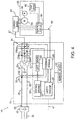
- Fig. 4 still another embodiment of the invention is illustrated.
- the current sensors 81 and the current sense circuit 80 are included within a connector 39 for the power cable 37 extending between the motor 40 and the motor drive 11.
- the second set of current sensors are able to measure the current supplied to each phase of the motor via the power cable 37 and provide the current feedback signals to the control circuit 84.
- the control circuit may additionally be included within the connector 39 of the cable 37.
- the control circuit 84 may be configured to receive temperature information from a temperature sensor 82 within the motor 40 and/or position feedback information from the position sensor 86.
- the connector 39 may be a plug, receiving the power cable 37 at one end and terminals for connection or insertion into a connector on the motor 40 at the other end.
- the connector 39 may be a junction box mountable to the motor 40 and configured to be connected to the power cable 37 and the motor 40.
- the second set of current sensors, current sense circuit, and/or control circuit 84 be located in a connector for the power cable 37 at the output of the motor drive 11 or in a junction box mounted at any suitable location between the motor drive 11 and the motor 40.
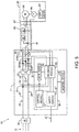
- a hardware dongle 85 or other such inline cable or device is provided between the motor drive 11 and the motor 40.
- the hardware dongle 85 includes a current sense circuit 80, current sensors 81, and a control circuit 84. Although illustrated as a single sensor, it is contemplated that three separate current sensors 81 may be provided with a separate sensor on each phase of the power output to the motor.
- the three phases between the motor drive 11 and the motor 40 are collapsed into a single line within the dongle 85 for ease of illustration.
- the hardware dongle 85 plugs into the output 35 of the motor drive 11 and is further configured to conduct position feedback information between the motor 40 and the motor drive.
- a single cable 87 plugs into the opposite side of the dongle 85 and includes conductors for the power from the motor drive 11 to the motor 40 as well as communication conductors between the position feedback device 86 and the motor drive.
- the three-phase output from the motor drive 11 is connected within the motor 40 to the stator of the motor body 88 itself to control rotation of the motor 40.
- the current sense circuit 80 may operate in a similar manner as discussed above to sample the current supplied to each phase of the motor 40.
- the control circuit 84 may be configured to intercept communication packets from the position feedback device 86 and insert current measurements in the communication packets before transmitting the communication packets to the motor drive 11. Alternately, the control circuit 84 may monitor communication traffic from the position feedback device 86 to the motor drive 11 and allow those packets to pass through the dongle 85 and intersperse additional communication packets with the measured current feedback data.
- the motor drive 11 may be configured to generate a second set of measured current data which is provided to the control circuit 50 in place of measured current data from a second set of current sensors 81.
- the control module 55 may receive current feedback signals from the current sensor 52 on the DC bus 25 which indicate the amount of current conducted on the DC bus.
- the current conducted from the DC bus 25 is provided to the motor via the inverter section 30 of the motor drive 11.
- an exemplary look-up table 90 is illustrated that defines the state of the transistors 32 at any given instant when the motor drive 11 is supplying current to the motor 40, where the state of each transistor 32 corresponds to the switching signal 31 supplied to the transistor.
- the motor drive 11 may reconstruct the current flowing in each phase of the motor 40. A portion of the current measured on the DC bus 25 will flow in each phase, with a different portion flowing in each phase as a function of the state of each transistor 32.
- the illustrated table 90 is a simplified six-step switching function. It is contemplated that various other look-up tables may be provided without deviating from the scope of the invention.
- the control module 55 samples the magnitude of current present on the DC bus 25 synchronously with sampling the magnitude of current present at the output 35 of the motor drive and reconstructs a second set of current feedback signals for the output as a function of the sampled DC bus current and the look-up table 90 stored in the memory device 45 of the motor drive 11.
- the reconstructed second set of current feedback signals may be provided to the feedback module 65 in place of signals from a second set of current sensors 81 or utilized directly within the control module 55 in place of feedback values obtained via the second set of current sensors 81.
- the motor drive 11 may independently calculate two different values of the torque being generated in the motor 40.
- the safety module 57 is configured to execute a first torque computation module 62 and a second torque computation module 64.
- the controller 50 may include a first processor and a second processor, where the first processor executes the first torque computation module 62 and the second processor executes the second torque computation module 64. If either processor fails, the other processor is still able to determine a level of torque being generated by the motor 40 and allow for a controlled shut down of the motor 40.
- both processors may execute both torque computation modules 62, 64 in a redundant manner and compare the torque values output from the modules on each of the respective processors to verify the computations.
- a flow diagram illustrates the steps taken in the first torque computation module 62 and in the second torque computation module 64, according to one embodiment of the invention, to provide a safe limited torque operation in the motor drive 11.
- the initial steps of Fig. 10 are used to determine the torque being produced in the motor using the two different torque computation modules 62, 64.
- Each of the torque computation modules 62, 64 utilizes the magnitude of current output to the motor 40 to independently determine a value of torque produced by the motor 40.
- the first torque computation module 62 uses the values of current measured with the first set of current sensors 54.
- the second torque computation module 64 uses the values of current measured with the second set of current sensors 81, as shown in step 202.
- each set of current sensors 54, 81 must sample the current in each phase of the motor in order to obtain the first and second set sets of measured value of the current, respectively.
- the current output in each phase of the motor 40 is an alternating current, varying between a maximum positive value and a maximum negative value.
- the voltage, and resulting current, in each phase of the motor is generated via a modulation technique, such as pulse width modulation, as previously discussed.
- the voltage supplied to each phase of the motor is alternately connected to either the positive rail 27, the negative rail 29, or a common connection.
- a dashed line 101 is indicative of a synchronizing signal 101 being passed between the sampling circuits for the first and second sets of sensors in order to obtain measured values of the current in tandem for each phase of the motor 40.
- the motor drive 11 includes a clock circuit that periodically generates a pulse to the position encoder 86 to transmit the position feedback information to the motor drive 11.
- the motor drive 11 may include a dedicated feedback circuit configured to communicate via the interface for the position feedback device 86.
- the dedicated feedback circuit may generate an initial control signal to initiate a communication cycle from the encoder 86 to the motor drive 11.
- the encoder 86 samples the data and writes the data to a memory location within the encoder for transmission to the motor drive 11.
- the encoder 86 may transmit the control signal to the current sense circuit 80 to cause the current on each phase of the motor 40 to be sampled by the second set of current sensors 81.
- a predefined delay time may exist between when the control signal is generated and when the current is sampled, including, for example, propagation delay in transmission, control sequence delays based on the order of execution of control instructions, and the like.
- the motor drive 11 may be configured to generate the control signal to initiate the current sampling by the second set of current sensors in the motor 40 at a first time and to initiate current sampling of the first set of current sensors 54 within the motor drive 11 at a second time, where the second time is delayed by the predefined delay time such that the first and second current sensors sample the first and second values of current in tandem.
- the pulse from the clock circuit or the signal to the encoder to initiate sampling in the motor correspond to the synchronizing signal 101 illustrated in the flow diagram to cause the first set of current values and the second set of current values to be obtained in tandem by the respective set of current sensors.
- the first torque computation module 62 determines a first value of torque produced by the motor 40.
- the electrical angle, ⁇ e of the motor is determined.
- the electrical angle, ⁇ e is used in step 106 to transform the first set of current values from the measured three-phrase reference from to a two-phase reference frame, such as the d-q reference frame.
- a first current, I q is defined as a torque producing current and is regulated to achieve a desired level of torque in the motor 40 and a second current, I d , is defined as a flux producing current and is regulated to achieve a desired level of flux across the air gap between the stator and the rotor in the motor 40.
- the first torque computation module 62 uses a measured value of temperature in the motor to compensate parameters used to determine the first torque value, and at step 110, the first torque computation module 62 determines a first value of the torque produced by the motor 40 according to a first function.
- the second torque computation module 64 determines a second value of torque produced by the motor 40.
- the electrical angle, ⁇ e of the motor is determined.
- the electrical angle, ⁇ e is used in step 206 to transform the first set of current values from the measured three-phrase reference from to a two-phase reference frame, such as the d-q reference frame.
- a first current, I q is defined as a torque producing current and is regulated to achieve a desired level of torque in the motor 40 and a second current, I d , is defined as a flux producing current and is regulated to achieve a desired level of flux across the air gap between the stator and the rotor in the motor 40.
- the second torque computation module 64 uses a measured value of temperature in the motor to compensate parameters used to determine the second torque value, and at step 210, the second torque computation module 64 determines a second value of the torque produced by the motor 40 according to a second function.
- the first function, executed by the first torque computation module 62, and the second function, executed by the second torque compensation module 64 may be identical.
- Two torque computation modules executing on separate processors may be used to verify the measurements from each set of current sensors. If the two functions are identical, that two modules should generate the same results with the same measured values. Verification of the computed torque values, as discussed further below, will provide increased reliability of the execution of each torque compensation module.
- the first and second functions, used by the first and second torque computation modules 62, 64, respectively, are different from each other.
- Use of diverse functions for determination of the torque values provides still an additional level of reliability of the system. If both torque computation modules 62, 64 use the same function, as indicated above, an error in one value of the calculation will generate an error in the calculation of the torque value. While comparison of the two outputs can verify that the measured values correspond to each other, if there is an error in the output of the calculation, both modules will generate the same erroneous value.
- an error in a value may still cause an erroneous output in one or both of the calculations.
- the motor drive 11 may include a compensation routine for the flux linkage values.
- the first torque computation module executes the compensation routine for the flux linkage values to adjust the value of the flux linkage as a function of the temperature in the motor 40.
- the temperature value measured by the temperature sensor 82 in the motor may be used to raise or lower the flux linkage value by a predefined amount, by a predefined percentage, according to a look-up table, according to a stored temperature compensation function, or the like.
- the compensated flux linkage value is then used in equation 1 above to determine the first value of torque in the motor.
- the second torque computation module 64 may utilize a torque constant, Kt, of the motor 40 to determine the second torque value.
- Kt a torque constant
- the torque constant, Kt corresponds to the design of the motor 40.
- the torque constant defines the amount of torque a motor is able to output for a given amount of current present in the motor.
- Motor design criteria such as the magnetic field strength in the motor, the number of turns in the winding, the armature length, and the like determine the torque constant. Some of these values, such as the magnetic field strength vary as a function of the temperature in the motor 40.
- the second torque computation module compensates the torque constant as a function of the temperature in the motor 40.
- the temperature value measured by the temperature sensor 82 in the motor may be used to raise or lower the torque constant by a predefined amount, by a predefined percentage, according to a look-up table, according to a stored temperature compensation function, or the like.
- the compensated torque constant is then used in equation 2 above to determine the second value of torque in the motor.
- steps 120-130 operate to verify that the two values correspond to each other. It is contemplated that either the first processor, executing steps 102-110, may perform the verification, or the second processor, executing steps 202-210, may perform the verification. Optionally, both the first and second processors may perform the verification and compare the results obtained by each processor to further improve the reliability of the system.
- the first value of torque is compared to the second value of torque. A difference between the two values is compared to a predefined threshold at step 122.
- the predefined threshold allows for a small variation between the two values without indicating an error condition, where it is contemplated that the two values may be allowed to vary from each other by up to ten percent of the measured value before starting the timer. If the two torque values are less than the predefined threshold, the motor drive 11 continues operation of the motor 40 according to the present command, as shown in step 132. If, however, the two torque values exceed the predefined threshold, the motor controller increments a clock, a counter, or a timer as shown in step 124.
- the current value of the timer is compared to a maximum allowed duration for the two values to be varying from each other, where it is contemplated that the two current values may be allowed to differ from each other beyond the first threshold for tens or hundreds of milliseconds. If the two values have differed from each other for the maximum allowed duration, the motor drive 11 brings the motor to a stop as shown in step 130. Steps 122, 124, 126, and 130 allow the two values to drift apart a small amount for a short duration without generating a fault message or bringing the motor to a stop.
- Step 1208 the motor drive 11 may also bring the motor to a stop. Steps 128 and 130 allow the motor controller to stop the motor immediately upon the two values drifting apart by too great a value without waiting for the duration of the timer indicated in steps 124 and 126. If the two values of torque differ by an amount greater than the first threshold, but less than the second threshold, and the timer has not yet expired, the motor controller continues operation of the motor, according to step 132.
- a second threshold such as a twenty percent difference in the measured values
- the first and second torque computation modules 62, 64 and the steps illustrated in Fig. 10 may be used in conjunction with an input signal that indicates a safe operating state is desired to provide one embodiment of a safe limited torque function in the motor drive 11.
- a safety device such as a safety mat, a gate switch, a key switch, a light curtain, or the like may detect the presence of a person interacting with the controlled machine or process and generate the input signal indicating that a safe operating state is desired. In one safe operating state, safe limited torque operation is desired.
- the motor drive 11 sets a limit on the magnitude of current being output to the motor 40 which, in turn, limits the amount of torque being generated by the motor 40.
- the safety module 57 executes the first and second torque computation modules 62, 64 as described above. The two modules are used to provide a verified value of the torque being produced by the motor 40. If the verified value of torque either exceeds the first threshold for the predefined duration or exceeds the second threshold, the safety module 57 executes a safe torque off sequence to stop operation of the motor 40, where the safe torque off removes power from the motor 40 and/or de-energizes brake coils, if present, for the motor 40, thereby setting the respective brake.
- one of the torque computation modules may be configured to execute within the motor 40.
- the first processor executing the first torque computation module 62 of the safety module 57 may be a processor within the motor drive 11.
- a second processor executing the second torque computation module 64 of the safety module 57 may be a processor on the control circuit 84 within the motor 40.
- the second set of current transducers 81 may receive a synchronizing sampling signal from the motor drive 11 such that the two sets of current values are measured in tandem.
- the control circuit 84 within the motor 40 may receive the measured motor temperature and execute one function to determine a value of the torque being generated by the motor 40.
- the second value of torque is transmitted back to the motor drive 11 to be compared to the first value of torque, as described above, rather than transmitting the measured current value.
Landscapes
- Engineering & Computer Science (AREA)
- Power Engineering (AREA)
- Microelectronics & Electronic Packaging (AREA)
- Control Of Electric Motors In General (AREA)
- Control Of Ac Motors In General (AREA)
Abstract
Description
- The subject matter disclosed herein relates generally to a system and method for providing safe limited force producing operation in a motor and, more specifically, to a system and method for obtaining multiple current measurements and executing multiple force producing calculations in order to achieve a desired safety rating when providing a force limiting function in a motor and motor drive combination.
- Electrical rotating machines, such as electric motors or generators, have become widespread and are found in numerous applications and configurations. Electric machines include a stationary component (i.e., the stator) and a rotating component (i.e., the rotor). In electric motors, a magnetic field is established in the rotor, for example via magnets mounted to the rotor or via an electrical current applied to or induced in a coil wound on the rotor. A second, rotating magnetic field is established as a result of a stator current produced by a controlled voltage applied to the stator. Rotation of the magnetic field in the stator causes the magnetic field in the rotor to follow the stator field, thereby causing rotation of the rotor. A shaft or other drive member is mounted to the rotor and extends outside the rotor housing providing a mechanical coupling to a device, such as a gearbox, pump, or fan that is to be driven as the rotor rotates. The amplitude and frequency of the controlled voltage applied to the stator is varied to achieve desired operation of the motor.
- As is known to those skilled in the art, motor controllers, also referred to herein as motor drives, are utilized to vary the amplitude and frequency of the voltage applied to a motor to achieve desired operation of the motor. A motor controller is configured to receive power at an input, where the input power may be supplied from either an alternating current (AC) source or a direct current (DC) source. If the input power is supplied from an AC source, a rectifier section converts the AC power to DC power. The DC bus, either from the output of the rectifier section or supplied directly from the DC source is provided to a DC bus within the motor controller. A current regulator and modulation techniques are used to control an inverter section which, in turn, supplies the required current and voltage to the motor from the DC bus to achieve desired operation of the motor.
- In certain applications, it may be desirable to operate the motor at a reduced torque level. For example, during commissioning, it may be desirable to limit the amount of torque output by the motor until it has been verified that the motor is being properly controlled by the motor drive. Alternately, the desired operation of an application may require the motor to operate at a limited torque. A spooling application, for example, may demand limited torque output from the motor to facilitate manual spooling of a material for a web. Historically, it has been known to provide an input to the motor drive to indicate that operation at the reduced torque level is required. The motor drive can adjust the maximum torque limit for the motor drive in response to receiving the input and, thereby, limit the torque produced by the motor.
- In still other applications, there may be a requirement of human interaction with the controlled machine or process, and it may be desirable to limit the amount of torque a motor may produce during this interaction to reduce or prevent the risk of injury during this interaction. When human interaction is required, the application typically requires a safety monitoring system with a high degree of certainty that the safety function will perform as intended. Simply providing an input to the motor drive and relying on the motor drive to respond to this input to limit torque, as previously described for limiting torque in a motor, does not typically satisfy the requirements of a safety monitoring system that is required during human interaction. Failure, for example, of a single component may allow the motor drive to continue operating at full torque rather than operating at the required limited torque and fails- to provide the desired degree of certainty that the limited torque function will perform as intended. The safety monitoring system may, therefore, require redundancy in the system to increase reliability. For example, the user interface may require two pushbuttons or two switches to be set to initiate a desired action. Similarly, the interface device may output two signals from two contactors which are wired in parallel back to a controller to provide two input signals which are monitored. Alternately, monitoring systems may be implemented in which additional feedback signals are provided to verify desired operation. For example, the push button may include a micro switch to detect that the button was pressed, where the micro switch sends an independent signal to the controller in parallel with the signal from the pushbutton.
- Despite the addition of redundant components or monitoring systems providing additional feedback, there is still a single point of failure present in applications requiring limited torque operation. A single motor drive is necessarily required to control operation of the motor. Thus, while some improvements in reliability may be obtained by redundant controls, the motor drive remains a single point of failure and has previously limited the safety rating of a system that may be obtained.
- Thus, it would be desirable to provide a motor drive with improved reliability, which, in turn, increases the degree of certainty that a safety monitoring system operates as intended during safe limited torque operation of a motor.
- The subject matter disclosed herein describes a motor drive with improved reliability, which, in turn, increases the degree of certainty that a safety monitoring system operates as intended during safe limited force producing operation of a motor. In a rotary motor, the safe limited force is a safe limited torque. In a linear motor, the safe limited force is a linear force along the direction of travel of the linear motor. For ease of discussion, the invention will be described with respect to a rotary motor and a safe limited torque. It is understood that the safe limited force determination may similarly be applied on a linear motor application without deviating from the scope of the invention. The motor drive utilizes redundant current feedback to monitor the torque being produced by a motor operatively controlled by the motor drive. A first set of current sensors is provided within the motor drive and measures the current being output to the motor. The first set of current sensors may be current sensors typically included within a motor drive and used to regulate the current output to the motor. In many applications, however, a motor drive utilizes two current sensors to monitor a three-phase current output to the motor. Each sensor measures the current in one of two phases and the current in the third phase is determined by assuming a balanced current exists in the three phases. In the present invention, it is contemplated that three current sensors are provided within the motor drive, where each sensor measurers the current provided to one phase of the motor. A second set of current sensors is provided in the system for redundant current feedback. The second set of sensors may be provided external to the motor drive. It is contemplated that the second set of current sensors is mounted in the motor. Optionally, the second set of sensors may be mounted in a junction box to which a motor cable is connected or within a connector of the motor cable supplying current from the motor drive to the motor. The current feedback from both sets of current sensors is provided to a controller within the motor drive to determine a level of torque being produced by the motor.
- The controller may be a single processor or redundant processors executing in parallel according to known techniques. The controller uses the feedback signals from the first current sensors to determine the torque produced by the motor according to a first torque calculation and uses the feedback signals from the second current sensors to determine the torque produced by the motor according to a second torque calculation. According to one aspect of the invention, the first and second torque calculations utilize different algorithms for determining the torque produced by the motor. The diversity of the algorithms increases the safety level of the controlled system. If the same algorithm is executed in a redundant manner, an error in a value used by the algorithm would generate the same erroneous output by both calculations. However, if there is an error in a value used by one of the algorithms, or even by both algorithms, while the output of each algorithm may be erroneous, it is less likely that the two algorithms will generate the same erroneous result.
- The controller then compares the output of the two algorithms to each other. If the controller is executing correctly, the output of the two algorithms should provide the same torque calculation within an acceptable band. If the output of the two torque calculations is the same, the controller continues operating as commanded. If the output of the two torque calculations differs beyond the acceptable band, then the controller may generate a fault message, safely stop operation of the motor, or a combination thereof.
- According to a first embodiment of the invention, a method for providing a safe limited force producing power in a motor is disclosed. A first value of a current present in each phase of a stator of the motor is measured with a first set of current sensors. A second value of the current present in each phase of the stator of the motor is determined, where determining the second value of the current present in each phase of the stator is synchronized in time with measuring the first value of the current present in each phase of the stator. A first value of a force produced by the motor is determined as a first function of the value of the current present in each phase of the stator, and a second value of the force produced by the motor is determined as a second function of the value of the current present in each phase of the stator. The first function is different than the second function, the first function uses the first value of the current, and the second function uses the second value of the current. An input signal, corresponding to a safe state of operation of the motor, is received at a motor drive, where the motor drive is operatively connected to control operation of the motor. Responsive to receiving the input signal, the motor drive is operative to limit the current output to the motor, compare the first value of the force to the second value of the force, and stop operation of the motor when the first value of the force differs from the second value of the force by more than a predefined value.
- According to another embodiment of the invention, a system for providing a safe limited force producing power is disclosed. The system includes a motor and a motor controller operatively connected to control operation of the motor. The motor has a stator, a rotor, and a housing in which the stator and rotor are mounted. The motor controller has a first set of current sensors and at least one processor. The first set of current sensors are operative to measure a first value of a current present in each phase of the stator. The at least one processor is operative to sample a first value of the current present in each phase of the stator from the first set of current sensors and to receive a second value of the current present in each phase of the stator from a second set of current sensors. The second set of current sensors are external to the motor controller, and a sampling circuit operatively connected to the second set of current sensors samples the second value of the current synchronously with the processor sampling the first value of the current. A first value of a force produced by the motor is determined as a first function of the value of the current present in each phase of the stator, and a second value of the force produced by the motor is determined as a second function of the value of the current present in each phase of the stator, where the second function is different than the first function. The first value of the force is compared to the second value of the force in the motor drive, and when the first value of the force differs from the second value of the force by more than a predefined value, operation of the motor is stopped.
- According to still another embodiment of the invention, a method for providing a safe limited force producing power in a motor is disclosed. The motor drive receives a first value of a current present in each phase of a stator of the motor and is operatively connected to control operation of the motor. The first value of the current is measured with a first set of current sensors. The motor drive determines a second value of the current present in each phase of the stator of the motor, where determining the second value of the current present in each phase of the stator is synchronized in time with measuring the first value of the current present in each phase of the stator. A first value of a force produced by the motor is determined as a first function of the value of the current present in each phase of the stator, and a second value of the force produced by the motor is determined as a second function of the value of the current present in each phase of the stator. The first function is different than the second function, the first function uses the first value of the current, and the second function uses the second value of the current. The first value of the force is compared to the second value of the force in the motor drive, and operation of the motor is stopped with the motor drive when the first value of the force differs from the second value of the force by more than a predefined value.
- These and other advantages and features of the invention will become apparent to those skilled in the art from the detailed description and the accompanying drawings. It should be understood, however, that the detailed description and accompanying drawings, while indicating preferred embodiments of the present invention, are given by way of illustration and not of limitation. Many changes and modifications may be made within the scope of the present invention without departing from the spirit thereof, and the invention includes all such modifications.
- Various exemplary embodiments of the subject matter disclosed herein are illustrated in the accompanying drawings in which like reference numerals represent like parts throughout, and in which:
-
FIG. 1 is an exemplary embodiment of a motor and a panel-mounted motor drive incorporating the present invention; -
FIG. 2 is an exemplary embodiment of a motor and an integrated motor drive incorporating the present invention; -
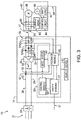
FIG. 3 is a schematic representation of the motor and motor drive according to one embodiment of the present invention; -
FIG. 4 is a schematic representation of the motor and motor drive according to another embodiment of the present invention; -
FIG. 5 is a schematic representation of the motor and motor drive according to still another embodiment of the present invention; -
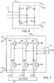
FIG. 6 is a schematic representation of a passive rectifier used inFigs. 3-5 ; -
FIG. 7 is a schematic representation of an inverter used inFigs. 3-5 ; -
FIG. 8 is a tabular representation of gating signals provided to the inverter ofFig. 7 according to one embodiment of the invention; -
FIG. 9 is a block diagram representation of the motor and motor drive ofFig. 3 ; and -
FIG. 10 is a flow diagram illustrating the steps for implementing safe limited torque operation in the motor according to one embodiment of the invention. - In describing the various embodiments of the invention which are illustrated in the drawings, specific terminology will be resorted to for the sake of clarity. However, it is not intended that the invention be limited to the specific terms so selected and it is understood that each specific term includes all technical equivalents which operate in a similar manner to accomplish a similar purpose. For example, the word "connected," "attached," or terms similar thereto are often used. They are not limited to direct connection but include connection through other elements where such connection is recognized as being equivalent by those skilled in the art.
- The various features and advantageous details of the subject matter disclosed herein are explained more fully with reference to the non-limiting embodiments described in detail in the following description.
- Turning initially to
Fig. 1 , amotor controller 10, which may be used in conjunction with the various embodiments of the invention disclosed herein, is illustrated. According to the exemplary embodiment, themotor controller 10 includes a front-end rectifier 20 and amotor drive 11. The front-end rectifier 20 is configured to receive a three-phase AC voltage 15 at an input to therectifier 20. Therectifier 20 may include any electronic device suitable for passive or active rectification as is understood in the art. With reference also toFig. 6 , the illustrated front-end rectifier 20 includes a set ofdiodes 22 forming a diode bridge that rectifies the three-phase AC voltage to a DC voltage on theDC bus 25. Optionally, therectifier section 20 may include other solid-state devices including, but not limited to, thyristors, silicon-controlled rectifiers (SCRs), insulated-gate bipolar transistors (IGBTs), power metal-oxide semiconductor field-effect transistors (MOSFETs), Silicon Carbide field-effect transistors (SiC FETs), Gallium Nitride field-effect transistors (GaN FETs), or other transistors or solid-state devices to convert theinput power 15 to a DC voltage for theDC bus 25. Optionally, the front-end rectifier may also include one or more capacitors connected in parallel, in series, or in a combination thereof across theDC bus 25, providing at least a portion of the DC bus capacitance in the system. The DC voltage is present between apositive rail 27 and anegative rail 29 of theDC bus 25. The magnitude of the DC voltage between the negative and positive rails, 29 and 27, is generally equal to the magnitude of the peak of the AC input voltage. One or more motor drives 11 may be connected to theDC bus 25 to receive the DC voltage present on the bus and to use the DC voltage to control one or motors connected to eachmotor drive 11. - According to the embodiment illustrated in
Fig. 1 , asingle motor drive 11 is connected to the front-end rectifier 20. A pair of conductive bus bars extend between the top of therectifier 20 and the top of thedrive 11 to provide the positive andnegative rails rectifier 20 to themotor drive 11. With reference also toFig. 3 , themotor drive 11 may include aDC bus capacitor 24 connected between the positive and negative rails, 27 and 29, to reduce the magnitude of the ripple voltage resulting from converting the AC voltage to a DC voltage. It is understood that theDC bus capacitor 24 may be a single capacitor or multiple capacitors connected in parallel, in series, or a combination thereof. Optionally, all or a portion of the DC bus capacitance may be provided in the front-end rectifier 20. TheDC bus 25 is connected in themotor drive 11 to aninverter section 30. Referring also toFig. 7 , theinverter section 30 consists of switching elements, such as transistors, thyristors, or SCRs as is known in the art. The illustratedinverter section 30 includes IGBTs 32 and a free-wheeling diode 34 connected in pairs between thepositive rail 27 and each phase of the output voltage as well as between thenegative rail 29 and each phase of the output voltage. Each of the IGBTs 32 receives gating signals 31 to selectively enable the transistors 32 and to convert the DC voltage from theDC bus 25 into a controlled three phase output voltage to themotor 40. When enabled, each transistor 32 connects therespective rail DC bus 25 to anelectrical conductor 33 connected between the transistor 32 and theoutput terminal 35. Theelectrical conductor 33 is selected according to the application requirements (e.g., the rating of the motor drive 11) and may be, for example, a conductive surface on a circuit board to which the transistors 32 are mounted or a bus bar connected to a terminal from a power module in which the transistors 32 are contained. Theoutput terminals 35 of themotor drive 11 may be connected to themotor 40 via acable 37 including electrical conductors connected to each of theoutput terminals 35. - Turning next to
Fig. 2 , a second embodiment of amotor controller 10, which may be used in conjunction with the various embodiments of the invention disclosed herein, is illustrated. In a manner similar to the motor controller illustrated inFig. 1 , themotor controller 10 includes a front-end rectifier 20 and amotor drive 11. The front-end rectifier 20 is configured to receive a three-phase AC voltage 15 at an input to therectifier 20, and to provide a DC voltage on aDC bus 25 as an output of therectifier 20. Therectifier 20 may include any electronic device suitable for passive or active rectification as is understood in the art. The magnitude of the DC voltage between the negative and positive rails, 29 and 27, is generally equal to the magnitude of the peak of the AC input voltage. One or more motor drives 11 may be connected to theDC bus 25 to receive the DC voltage present on the bus and to use the DC voltage to control one or motors connected to eachmotor drive 11. - Unlike the
motor controller 10 illustrated inFig. 1 , themotor drive 11 illustrated inFig. 2 is mounted to themotor 40. Just as withFig. 1 , asingle motor drive 11 is shown inFig. 2 being connected to the front-end rectifier 20. ADC bus cable 25 extends between the front-end rectifier 20 and theintegrated motor drive 11 to provide the positive andnegative rails rectifier 20 to themotor drive 11. Optionally, the front-end rectifier may provide DC voltage to multiple integrated motor drives 11 mounted tomotors 40 and distributed around the controlled machine or process. Other than the mounting location, the motor drive is configured in a manner similar to the motor drive shown inFig. 1 and discussed above with respect toFig. 3 . Because themotor drive 11 is mounted to themotor 40, short leads or bus bars may be connected between theoutput terminals 35 of themotor drive 11 and the stator terminals of themotor 40. Optionally, the stator windings may be connected directly to theoutput terminals 35 of themotor drive 11. - One or more modules are used to control operation of the
motor drive 11. With reference again toFig. 3 , acontroller 50 includes the modules and manages execution of the modules. The illustrated embodiment is not intended to be limiting and it is understood that various features of each module discussed below may be executed by another module and/or various combinations of other modules may be included in thecontroller 50 without deviating from the scope of the invention. The modules may be stored programs executed on one or more processors, logic circuits, or a combination thereof. Thecontroller 50 may be implemented, for example, in one or more microprocessors, application specific integrated circuits (ASICs), field programmable gate arrays (FPGAs), or other such customizable device. Themotor drive 11 also includes amemory device 45 in communication with thecontroller 50. Thememory device 45 may include transitory memory, non-transitory memory or a combination thereof. Thememory device 45 may be configured to store data and programs, which include a series of instructions executable by thecontroller 50. It is contemplated that thememory device 45 may be a single device, multiple devices, or incorporated, for example, as a portion of another device such as an application specific integrated circuit (ASIC). Thecontroller 50 is in communication with thememory 45 to read the instructions and data as required to control operation of themotor drive 11. - The
controller 50 receives a reference signal identifying desired operation of themotor 40 connected to themotor drive 11. The reference signal may be, for example, a position reference (θ*), a speed reference (ω*), or a torque reference (T*). For discussion purposes herein, the reference signal will be considered as a position reference signal (θ*). The reference signal may be received from another controller, such as a programmable logic controller (PLC), programmable automation controller (PAC) or the like via anindustrial network 47. Theindustrial network 47 may be any suitable network including, but not limited to, Ethernet/IP, DeviceNet, or ControlNet. Although a single cable 47 (see e.g.,Fig. 3 ) is illustrated as representing the network, it is contemplated that the network may be implemented in a redundant manner with parallel network cables, network devices, network interfaces, and the like to achieve a desired reliability and/or safety rating for the system. Asafety module 57 executing in thecontroller 50 may receive the reference signal from the safety network. It is contemplated that thesafety module 57 may be a pair of modules executing in a redundant manner on a pair of processors in thecontroller 50 with a synchronization routine verifying that the same reference signal is received from thenetwork 47 at each of the processors. After performing the safety verification, thesafety module 57 will pass the reference signal to acontrol module 55 to regulate operation of themotor 40 according to the reference signal. - The
controller 50 also receives feedback signals indicating the current operation of themotor drive 11. According to the illustrated embodiment, thecontroller 50 includes afeedback module 65 that may include, but is not limited to, analog to digital (A/D) converters, buffers, amplifiers, and any other components that would be necessary to convert a feedback signal in a first format to a signal in a second format suitable for use by thecontroller 50 as would be understood in the art Themotor drive 11 may include avoltage sensor 51 and/or acurrent sensor 52 on theDC bus 25 generating a feedback signal corresponding to the magnitude of voltage and/or current present on theDC bus 25. Themotor drive 11 may also include one ormore voltage sensors 53 and/orcurrent sensors 54 on the output phase(s) of theinverter section 30 generating a feedback signal corresponding to the magnitude of voltage and/or current present on theelectrical conductors 33 between theinverter section 30 and theoutput 35 of the motor drive. Aposition feedback device 86 such as an encoder or resolver may be connected to themotor 40 to generate a position feedback signal corresponding to an angular position of themotor 40. It is further contemplated that theposition feedback device 86 may be a safety rated position feedback device, wherein the safety rated position feedback device may include: dual sensors internal to the device to monitor determine the angular position of the motor, dual channels to pass the angular position information through the device, a safety rated communications protocol, and/or onboard diagnostic routines to verify proper operation of the device. - The
controller 50 utilizes the feedback signals and the reference signal to control operation of theinverter section 30 to generate an output voltage having a desired magnitude and frequency for themotor 40. The feedback signals are processed by thefeedback module 65 and converted, as necessary, to signals for thecontrol module 55. Thecontrol module 55 also receives the reference signal and executes responsive to the reference signal and the feedback signals to generate a desired output voltage signal to agate driver module 60. Thegate driver module 60 generates the gating signals 31, for example, by pulse width modulation (PWM) or by other modulation techniques. The gating signals 31 subsequently enable/disable the transistors 32 to provide the desired output voltage to themotor 40, which, in turn, results in the desired operation of the mechanical load 42 coupled to themotor 40. - In operation, one or more modules executable by the
controller 50 are operative to provide a safe limited torque operation of themotor 40 connected to themotor drive 11. Themotor drive 11 may receive an input signal indicating that a safe state of operation, such as the safe limited torque operation, is desired. The input signal may be transmitted from another controller such as a PLC, connected to themotor drive 11, via thenetwork 47. Optionally, a safety device, such as a safety mat, a gate switch, a key switch, a light curtain, or the like may detect the presence of a person interacting with the controlled machine or process and generate an input signal that is connected directly to an input on themotor drive 11. When the input signal indicates safe limited torque operation is desired, themotor drive 11 limits the magnitude of current being output to themotor 40 which, in turn, limits the amount of torque being generated by themotor 40. - In order to achieve a desired safety rating the
motor drive 11 andmotor 40 utilize redundant feedback systems to monitor the magnitude of torque generated by themotor 40. As discussed above, thecontroller 50 receives feedback signals such as current feedback signals and position feedback signals corresponding to operation of the motor. The current feedback signals are sampled synchronously in time with the position feedback signals. The position feedback signals are utilized to determine both the angular position of the motor, a mechanical angle, and the electrical angle of the current. The electrical angle of the current is used in combination with the magnitude of the measured currents to determine transformed current values in the d and q axes which, as discussed below, are utilized to determine the torque produced by the motor. Therefore, to improve the accuracy of the transformed current values it is desirable to sample the currents and position feedback signals synchronously with each other. - The present inventors selected the current feedback signals to monitor the magnitude of torque for an improved response time in determining the torque produced by the motor. While position feedback signals may be monitored, and in some applications are utilized, to determine torque output by the motor, position feedback signals introduce some delay in determining the level of torque output by the motor. Utilizing a position feedback signal to monitor for a change in the level of torque output by the motor first requires detecting a change in the speed of the motor. The angular position provided by the position feedback signal is monitored over at least two sampling periods to determine an angular velocity over the duration. A change in angular velocity, therefore, requires monitoring over a third sampling period to detect a change in angular velocity. Further, the change in angular velocity is a result of increasing current creating a change in torque applied to the motor and the motor, in turn, changing speed as a result of the change in torque. Thus, detecting a change in torque as a result of monitoring the position feedback signal inherently includes delays in the calculation resulting from waiting for the change in current to create a change in torque generated by the motor and, thereby changing the angular velocity of the motor. In contrast, monitoring the current feedback allows the
motor drive 11 to detect a change in the level of torque being supplied to themotor 40 as the torque is being generated by the motor. An increase in current will result in an increase of torque generated by the motor and, subsequently, a change in the angular velocity of the motor. However, by monitoring the current feedback, themotor drive 11 is able to detect the change in torque before the change in torque could be determined by monitoring changes in angular velocity of the motor. - In many applications, a
motor drive 11 includescurrent sensors 54 to measure only two phases of current output to themotor 40. Because themotor drive 11 is configured to output a balanced three-phase current, the sum of the currents adds up to zero. Thus, the magnitude of current in the third phase can be determined by subtracting the magnitude of the two measured phases from zero. Using twosensors 54 in amotor drive 11 reduces cost, requires less space within the drive, and, additionally, avoids potential challenges in regulating the current output to the motor if the motor current appears unbalanced to the motor controller, for example, due to an offset present in a feedback signal, precision of an analog to digital conversion, and the like that may otherwise result in the sum of all three phases being something other than zero. If threesensors 54 are utilized for regulating the current output to themotor 40, the regulator may attempt to eliminate measurement and/or feedback offsets or tolerance errors creating an instability in the current regulation. - In this application, however, the reliability of the
motor drive 11 and, therefore, the safety rating may be increased by utilizing a separatecurrent sensor 54 on each phase of theoutput 35 supplied to themotor 40. The three phases may be added together to verify that the current is balanced within an acceptable tolerance level. Thus, themotor drive 11 is able to perform a check on whether thecurrent sensors 54 are operating as expected. Further, if onesensor 54 fails, the other two may still be utilized to measure current output to the motor until the failedsensor 54 is repaired or replaced. Thus, themotor drive 11 is able to continue operation even if there is a single failure in one of the three current sensors. - To further increase the safety rating, a second set of
current sensors 81 are provided in the system. The second set ofcurrent sensors 81 also measure current in all three phases output to themotor 40. With reference toFig. 3 , a first embodiment of the invention includes the second set ofcurrent sensors 81 within themotor 40. According to the illustrated embodiment, thesensors 81 are transducers, such as a coil or current measurement resistor that generate a voltage and/or a current signal corresponding to a magnitude of current being sensed. The illustratedmotor 40 also includes acurrent sense circuit 80 which receives the signals from the sensors and may perform, for example, filtering or analog-to-digital conversion on the signals from the sensors or additionally may regulate the timing at which sampling occurs. Although illustrated as separate elements, it is contemplated that a portion or the entirety of thecurrent sense circuit 80 may be incorporated into a single housing with the transducer to provide a current sensor. - The measured current in each phase of the
motor 40 is, in turn, provided to acontrol circuit 84 mounted within the motor. According to one embodiment of the invention, thecontrol circuit 84 is operative to manage data collected within themotor 40 and facilitate transmission of the data back to themotor drive 11. Thecontrol circuit 84 may include a non-transitory memory to store parameters, control instructions, a microprocessor to execute instructions, logic circuits to perform specific functions, one or more buffers, communication circuitry, and the like, or a combination thereof. Thecontrol circuit 84 may also receive a temperature feedback signal from atemperature sense circuit 82 which includes a temperature transducer and any necessary circuit elements to filter, process, and/or transmit the temperature signal from the transducer to thecontrol circuit 84. Thecontrol circuit 84 is further in communication with theposition sensor 86 connected to themotor 40. According to one embodiment of the invention, thecontrol circuit 84 receives position feedback signals from theposition sensor 86 and assembles the current feedback signals, temperature feedback signals, and position feedback signals into data packets for communication to themotor drive 11. Acommunication cable 49 is connected between themotor 40 and themotor drive 11 and thecontrol circuit 84 formats and transmits data packets between themotor 40 and themotor drive 11 with the feedback information. Alternately, thecommunication cable 49 and thepower cable 37 may be integrated into a single cable extending between themotor drive 11 and themotor 40. - According to another embodiment of the invention, the
position sensor 86 may include a communication interface by which position information and additional data may be transmitted to themotor drive 11. Exemplary interfaces include, but are not limited to the EnDat®, HIPERFACE DSL®, or SCS open link® interfaces utilized in various encoders. Thecontrol circuit 84 may transmit the current feedback information and the temperature feedback information to theposition sensor 86 which, in turn, includes the feedback information as additional data when position feedback information is transmitted to themotor drive 11. According to either embodiment, themotor drive 11 receives the values of the current measured for each phase of themotor 40 by the second set ofcurrent sensors 81 and the measured values of the temperature in themotor 40 in addition to position feedback information from themotor 40. - Turning next to
Fig. 4 , still another embodiment of the invention is illustrated. Rather than including the current sensors within themotor 40, it is contemplated that thecurrent sensors 81 and thecurrent sense circuit 80 are included within aconnector 39 for thepower cable 37 extending between themotor 40 and themotor drive 11. The second set of current sensors are able to measure the current supplied to each phase of the motor via thepower cable 37 and provide the current feedback signals to thecontrol circuit 84. Optionally, it is further contemplated that the control circuit may additionally be included within theconnector 39 of thecable 37. Thecontrol circuit 84 may be configured to receive temperature information from atemperature sensor 82 within themotor 40 and/or position feedback information from theposition sensor 86. Theconnector 39 may be a plug, receiving thepower cable 37 at one end and terminals for connection or insertion into a connector on themotor 40 at the other end. Optionally, theconnector 39 may be a junction box mountable to themotor 40 and configured to be connected to thepower cable 37 and themotor 40. Providing the second set ofcurrent sensors 81 and/or thecontrol circuit 84 external to themotor 40 allows thesensors 81 to be added to existingmotor 40 as an upgrade to achieve a desired safety rating in an application. - According to still other embodiments of the invention, it is contemplated that the second set of current sensors, current sense circuit, and/or
control circuit 84 be located in a connector for thepower cable 37 at the output of themotor drive 11 or in a junction box mounted at any suitable location between themotor drive 11 and themotor 40. With reference, for example, toFig. 5 ahardware dongle 85 or other such inline cable or device is provided between themotor drive 11 and themotor 40. Thehardware dongle 85 includes acurrent sense circuit 80,current sensors 81, and acontrol circuit 84. Although illustrated as a single sensor, it is contemplated that three separatecurrent sensors 81 may be provided with a separate sensor on each phase of the power output to the motor. The three phases between themotor drive 11 and themotor 40 are collapsed into a single line within thedongle 85 for ease of illustration. As illustrated, thehardware dongle 85 plugs into theoutput 35 of themotor drive 11 and is further configured to conduct position feedback information between themotor 40 and the motor drive. Asingle cable 87 plugs into the opposite side of thedongle 85 and includes conductors for the power from themotor drive 11 to themotor 40 as well as communication conductors between theposition feedback device 86 and the motor drive. The three-phase output from themotor drive 11 is connected within themotor 40 to the stator of themotor body 88 itself to control rotation of themotor 40. Thecurrent sense circuit 80 may operate in a similar manner as discussed above to sample the current supplied to each phase of themotor 40. Thecontrol circuit 84 may be configured to intercept communication packets from theposition feedback device 86 and insert current measurements in the communication packets before transmitting the communication packets to themotor drive 11. Alternately, thecontrol circuit 84 may monitor communication traffic from theposition feedback device 86 to themotor drive 11 and allow those packets to pass through thedongle 85 and intersperse additional communication packets with the measured current feedback data. - According to yet another embodiment of the invention, it is contemplated that the
motor drive 11 may be configured to generate a second set of measured current data which is provided to thecontrol circuit 50 in place of measured current data from a second set ofcurrent sensors 81. Thecontrol module 55 may receive current feedback signals from thecurrent sensor 52 on theDC bus 25 which indicate the amount of current conducted on the DC bus. The current conducted from theDC bus 25 is provided to the motor via theinverter section 30 of themotor drive 11. With reference toFig. 8 , an exemplary look-up table 90 is illustrated that defines the state of the transistors 32 at any given instant when themotor drive 11 is supplying current to themotor 40, where the state of each transistor 32 corresponds to the switchingsignal 31 supplied to the transistor. Three of the transistors 32 will be on while three of the transistors will be off. Based on which set of transistors is conducting, themotor drive 11 may reconstruct the current flowing in each phase of themotor 40. A portion of the current measured on theDC bus 25 will flow in each phase, with a different portion flowing in each phase as a function of the state of each transistor 32. The illustrated table 90 is a simplified six-step switching function. It is contemplated that various other look-up tables may be provided without deviating from the scope of the invention. Thecontrol module 55 samples the magnitude of current present on theDC bus 25 synchronously with sampling the magnitude of current present at theoutput 35 of the motor drive and reconstructs a second set of current feedback signals for the output as a function of the sampled DC bus current and the look-up table 90 stored in thememory device 45 of themotor drive 11. The reconstructed second set of current feedback signals may be provided to thefeedback module 65 in place of signals from a second set ofcurrent sensors 81 or utilized directly within thecontrol module 55 in place of feedback values obtained via the second set ofcurrent sensors 81. - With the current feedback signals from both the first set of
current sensors 54 and the second set ofcurrent sensors 81, themotor drive 11 may independently calculate two different values of the torque being generated in themotor 40. With reference also toFig. 9 , it is contemplated that thesafety module 57 is configured to execute a firsttorque computation module 62 and a secondtorque computation module 64. To further reduce the likelihood of a single failure causing undesired operation of the motor, thecontroller 50 may include a first processor and a second processor, where the first processor executes the firsttorque computation module 62 and the second processor executes the secondtorque computation module 64. If either processor fails, the other processor is still able to determine a level of torque being generated by themotor 40 and allow for a controlled shut down of themotor 40. Optionally, both processors may execute bothtorque computation modules - Turning next to
Fig. 10 , a flow diagram illustrates the steps taken in the firsttorque computation module 62 and in the secondtorque computation module 64, according to one embodiment of the invention, to provide a safe limited torque operation in themotor drive 11. The initial steps ofFig. 10 are used to determine the torque being produced in the motor using the two differenttorque computation modules torque computation modules motor 40 to independently determine a value of torque produced by themotor 40. As shown instep 102, the firsttorque computation module 62 uses the values of current measured with the first set ofcurrent sensors 54. Similarly, the secondtorque computation module 64 uses the values of current measured with the second set ofcurrent sensors 81, as shown instep 202. - As further indicated in
steps current sensors motor 40 is an alternating current, varying between a maximum positive value and a maximum negative value. Additionally, the voltage, and resulting current, in each phase of the motor is generated via a modulation technique, such as pulse width modulation, as previously discussed. Thus, the voltage supplied to each phase of the motor is alternately connected to either thepositive rail 27, thenegative rail 29, or a common connection. Although the change in the resultant current is limited as a result of the inductance in the winding of each phase of the stator, the values of the current output to the motor are constantly changing due to the alternating nature, the modulation of the motor drive, electromagnetic interference between phases, and numerous other sources. Consequently, in order to independently sample the current in each phase of the motor and to then independently determine values of torque produced by the motor at any instant in time from the two different sets of samples, it is desirable to synchronize the instant at which sampling of the current occurs in each set of current sensors. With reference toFig. 10 , a dashedline 101 is indicative of asynchronizing signal 101 being passed between the sampling circuits for the first and second sets of sensors in order to obtain measured values of the current in tandem for each phase of themotor 40. - According to one embodiment of the invention, the
motor drive 11 includes a clock circuit that periodically generates a pulse to theposition encoder 86 to transmit the position feedback information to themotor drive 11. Optionally, themotor drive 11 may include a dedicated feedback circuit configured to communicate via the interface for theposition feedback device 86. The dedicated feedback circuit may generate an initial control signal to initiate a communication cycle from theencoder 86 to themotor drive 11. As one step in the communication cycle, theencoder 86 samples the data and writes the data to a memory location within the encoder for transmission to themotor drive 11. Similarly, theencoder 86 may transmit the control signal to thecurrent sense circuit 80 to cause the current on each phase of themotor 40 to be sampled by the second set ofcurrent sensors 81. A predefined delay time may exist between when the control signal is generated and when the current is sampled, including, for example, propagation delay in transmission, control sequence delays based on the order of execution of control instructions, and the like. Themotor drive 11 may be configured to generate the control signal to initiate the current sampling by the second set of current sensors in themotor 40 at a first time and to initiate current sampling of the first set ofcurrent sensors 54 within themotor drive 11 at a second time, where the second time is delayed by the predefined delay time such that the first and second current sensors sample the first and second values of current in tandem. With reference again toFig. 10 , the pulse from the clock circuit or the signal to the encoder to initiate sampling in the motor correspond to the synchronizingsignal 101 illustrated in the flow diagram to cause the first set of current values and the second set of current values to be obtained in tandem by the respective set of current sensors. - With reference to steps 104-110 of
Fig. 10 , the firsttorque computation module 62 determines a first value of torque produced by themotor 40. Atstep 104, the electrical angle, θe, of the motor is determined. The electrical angle, θe, is used instep 106 to transform the first set of current values from the measured three-phrase reference from to a two-phase reference frame, such as the d-q reference frame. In the d-q reference frame, a first current, Iq, is defined as a torque producing current and is regulated to achieve a desired level of torque in themotor 40 and a second current, Id, is defined as a flux producing current and is regulated to achieve a desired level of flux across the air gap between the stator and the rotor in themotor 40. Atstep 108, the firsttorque computation module 62 uses a measured value of temperature in the motor to compensate parameters used to determine the first torque value, and atstep 110, the firsttorque computation module 62 determines a first value of the torque produced by themotor 40 according to a first function. - With reference to steps 204-210 of
Fig. 10 , the secondtorque computation module 64 determines a second value of torque produced by themotor 40. Atstep 204, the electrical angle, θe, of the motor is determined. The electrical angle, θe, is used instep 206 to transform the first set of current values from the measured three-phrase reference from to a two-phase reference frame, such as the d-q reference frame. In the d-q reference frame, a first current, Iq, is defined as a torque producing current and is regulated to achieve a desired level of torque in themotor 40 and a second current, Id, is defined as a flux producing current and is regulated to achieve a desired level of flux across the air gap between the stator and the rotor in themotor 40. Atstep 208, the secondtorque computation module 64 uses a measured value of temperature in the motor to compensate parameters used to determine the second torque value, and atstep 210, the secondtorque computation module 64 determines a second value of the torque produced by themotor 40 according to a second function. - According to one aspect of the invention, the first function, executed by the first
torque computation module 62, and the second function, executed by the secondtorque compensation module 64, may be identical. Two torque computation modules executing on separate processors may be used to verify the measurements from each set of current sensors. If the two functions are identical, that two modules should generate the same results with the same measured values. Verification of the computed torque values, as discussed further below, will provide increased reliability of the execution of each torque compensation module. - According to another aspect of the invention, it is contemplated that the first and second functions, used by the first and second
torque computation modules torque computation modules torque computation modules - It is contemplated that the first
torque computation module 62 may utilize the flux linkages in themotor 40 to determine the first torque value. As illustrated inequation 1 below, the current values and the flux linkage values in the d-q reference frame may be used to determine a value of torque being produced by themotor 40.
- T1 is the first torque value,
- P is the number of poles in the motor,
- λ is the value of the flux linkage in either the d or q axis, and
- I is the value of current in either the d or q axis.
- As the temperature varies in the
motor 40, the flux produced within the motor also varies. As a result, themotor drive 11 may include a compensation routine for the flux linkage values. Atstep 108, the first torque computation module executes the compensation routine for the flux linkage values to adjust the value of the flux linkage as a function of the temperature in themotor 40. The temperature value measured by thetemperature sensor 82 in the motor may be used to raise or lower the flux linkage value by a predefined amount, by a predefined percentage, according to a look-up table, according to a stored temperature compensation function, or the like. The compensated flux linkage value is then used inequation 1 above to determine the first value of torque in the motor. - It is contemplated that the second
torque computation module 64 may utilize a torque constant, Kt, of themotor 40 to determine the second torque value. As illustrated inequation 2 below, the torque constant is a predefined value for a motor and is multiplied by the value of current in the q axis to determine a value of torque being produced by the motor 40
- T2 is the second torque value,
- Kt is a torque constant defined for the motor, and
- Iq is the current in the q axis.
- The torque constant, Kt, corresponds to the design of the
motor 40. The torque constant defines the amount of torque a motor is able to output for a given amount of current present in the motor. Motor design criteria such as the magnetic field strength in the motor, the number of turns in the winding, the armature length, and the like determine the torque constant. Some of these values, such as the magnetic field strength vary as a function of the temperature in themotor 40. Atstep 208, the second torque computation module compensates the torque constant as a function of the temperature in themotor 40. The temperature value measured by thetemperature sensor 82 in the motor may be used to raise or lower the torque constant by a predefined amount, by a predefined percentage, according to a look-up table, according to a stored temperature compensation function, or the like. The compensated torque constant is then used inequation 2 above to determine the second value of torque in the motor. - Turning again to
Fig. 10 , after the first and second values of the torque generated in themotor 40 are determined, steps 120-130 operate to verify that the two values correspond to each other. It is contemplated that either the first processor, executing steps 102-110, may perform the verification, or the second processor, executing steps 202-210, may perform the verification. Optionally, both the first and second processors may perform the verification and compare the results obtained by each processor to further improve the reliability of the system. Atstep 120, the first value of torque is compared to the second value of torque. A difference between the two values is compared to a predefined threshold atstep 122. The predefined threshold allows for a small variation between the two values without indicating an error condition, where it is contemplated that the two values may be allowed to vary from each other by up to ten percent of the measured value before starting the timer. If the two torque values are less than the predefined threshold, themotor drive 11 continues operation of themotor 40 according to the present command, as shown instep 132. If, however, the two torque values exceed the predefined threshold, the motor controller increments a clock, a counter, or a timer as shown instep 124. Atstep 126, the current value of the timer is compared to a maximum allowed duration for the two values to be varying from each other, where it is contemplated that the two current values may be allowed to differ from each other beyond the first threshold for tens or hundreds of milliseconds. If the two values have differed from each other for the maximum allowed duration, themotor drive 11 brings the motor to a stop as shown instep 130.Steps step 128, themotor drive 11 may also bring the motor to a stop.Steps steps step 132. - The first and second
torque computation modules Fig. 10 may be used in conjunction with an input signal that indicates a safe operating state is desired to provide one embodiment of a safe limited torque function in themotor drive 11. As previously indicated, a safety device, such as a safety mat, a gate switch, a key switch, a light curtain, or the like may detect the presence of a person interacting with the controlled machine or process and generate the input signal indicating that a safe operating state is desired. In one safe operating state, safe limited torque operation is desired. Themotor drive 11 sets a limit on the magnitude of current being output to themotor 40 which, in turn, limits the amount of torque being generated by themotor 40. While the input signal is present, indicating that operation of themotor 40 in the safe operating state is desired, thesafety module 57 executes the first and secondtorque computation modules motor 40. If the verified value of torque either exceeds the first threshold for the predefined duration or exceeds the second threshold, thesafety module 57 executes a safe torque off sequence to stop operation of themotor 40, where the safe torque off removes power from themotor 40 and/or de-energizes brake coils, if present, for themotor 40, thereby setting the respective brake. - According to another aspect of the invention, it is contemplated that one of the torque computation modules may be configured to execute within the
motor 40. The first processor executing the firsttorque computation module 62 of thesafety module 57 may be a processor within themotor drive 11. A second processor executing the secondtorque computation module 64 of thesafety module 57 may be a processor on thecontrol circuit 84 within themotor 40. The second set ofcurrent transducers 81 may receive a synchronizing sampling signal from themotor drive 11 such that the two sets of current values are measured in tandem. However, rather than transmitting the current values back to the motor drive, thecontrol circuit 84 within themotor 40 may receive the measured motor temperature and execute one function to determine a value of the torque being generated by themotor 40. The second value of torque is transmitted back to themotor drive 11 to be compared to the first value of torque, as described above, rather than transmitting the measured current value. - It should be understood that the invention is not limited in its application to the details of construction and arrangements of the components set forth herein. The invention is capable of other embodiments and of being practiced or carried out in various ways. Variations and modifications of the foregoing are within the scope of the present invention. It also being understood that the invention disclosed and defined herein extends to all alternative combinations of two or more of the individual features mentioned or evident from the text and/or drawings. All of these different combinations constitute various alternative aspects of the present invention. The embodiments described herein explain the best modes known for practicing the invention and will enable others skilled in the art to utilize the invention.
-
-
Embodiment 1. A method for providing a safe limited force producing power in a motor, the method comprising the steps of:- measuring a first value of a current present in each phase of a stator of the motor with a first set of current sensors;
- determining a second value of the current present in each phase of the stator of the motor, wherein determining the second value of the current present in each phase of the stator is synchronized in time with measuring the first value of the current present in each phase of the stator;
- determining a first value of a force produced by the motor as a first function of the value of the current present in each phase of the stator;
- determining a second value of the force produced by the motor as a second function of the value of the current present in each phase of the stator, wherein:
- the first function is different than the second function,
- the first function uses the first value of the current, and
- the second function uses the second value of the current;
- receiving an input signal, corresponding to a safe state of operation of the motor, at a motor drive, wherein the motor drive is operatively connected to control operation of the motor; and
- responsive to receiving the input signal, the motor drive is operative to:
- limit the current output to the motor,
- compare the first value of the force to the second value of the force, and
- when the first value of the force differs from the second value of the force by more than a predefined value, stop operation of the motor.
-
Embodiment 2. The method ofembodiment 1 further comprising the steps of measuring a temperature in the motor;
transmitting the measured temperature to the motor drive; and
compensating the first and second values of the force in the motor drive as a function of the temperature measured in the motor. -
Embodiment 3. The method ofembodiment 1 wherein the first set of current sensors is present within the motor drive. -
Embodiment 4. The method ofembodiment 3 wherein the second value of the current present in each phase of the stator of the motor is determined by measuring the value of the current present in each phase with a second set of current sensors. -
Embodiment 5. The method ofembodiment 4 wherein the second set of current sensors is present in the motor. -
Embodiment 6. The method ofembodiment 5 wherein the second value of the current is transmitted to the motor drive and wherein the motor drive is operative to determine the second value of the force produced by the motor. -
Embodiment 7. The method ofembodiment 5 wherein the second value of the force produced by the motor is determined by a control circuit in the motor and the second value of the force is transmitted to the motor drive. - Embodiment 8. The method of
embodiment 4 wherein the second set of current sensors is present in a connector for a power cable connected between the motor drive and the motor. - Embodiment 9. The method of
embodiment 3 wherein the second value of the current present in each phase of the stator of the motor is determined by the following steps:- measuring a value of the current present on a DC bus in the motor drive,
- reading a look-up table which defines which phase of the motor is conducting as a function of a plurality of gating signals controlling operation of an inverter section in the motor drive; and
- reconstructing the value of the current present in each phase of the stator as a function of the value of current measured on the DC bus and of the plurality of gating signals in the look-up table.
-
Embodiment 10. A system for providing a safe limited force producing power, comprising:- a motor, including a stator, a rotor, and a housing in which the stator and rotor are mounted; and
- a motor controller operatively connected to control operation of the motor, the motor controller including:
- a first set of current sensors operative to measure a first value of a current present in each phase of the stator; and
- at least one processor operative to:
- sample a first value of the current present in each phase of the stator from the first set of current sensors,
- receive a second value of the current present in each phase of the stator from a second set of current sensors, wherein the second set of current sensors are external to the motor controller and wherein a sampling circuit operatively connected to the second set of current sensors samples the second value of the current synchronously with the processor sampling the first value of the current,
- determine a first value of a force produced by the motor as a first function of the value of the current present in each phase of the stator,
- determine a second value of the force produced by the motor as a second function of the value of the current present in each phase of the stator, wherein the second function is different than the first function,
- compare the first value of the force to the second value of the force in the motor drive, and
- when the first value of the force differs from the second value of the force by more than a predefined value, stop operation of the motor.
-
Embodiment 11. The system ofembodiment 10 wherein the sampling circuit and the second set of current sensors are each present in the housing of the motor. - Embodiment 12. The system of
embodiment 10 wherein the sampling circuit and the second set of current sensors are each present in a connector for a power cable connected between the motor drive and the motor. - Embodiment 13. The system of
embodiment 10 further comprising a temperature sensor mounted in the motor to generate a temperature signal corresponding to a temperature in the stator of the motor, wherein the temperature signal is transmitted to the motor controller and wherein the at least one processor is further operative to compensate the first and second values of the force as a function of the temperature signal. - Embodiment 14. A method for providing a safe limited force producing power in a motor, the method comprising the steps of:
- receiving a first value of a current present in each phase of a stator of the motor at a motor drive, wherein the first value of the current is measured with a first set of current sensors and wherein the motor drive is operatively connected to control operation of the motor;
- determining a second value of the current present in each phase of the stator of the motor at the motor drive, wherein determining the second value of the current present in each phase of the stator is synchronized in time with measuring the first value of the current present in each phase of the stator;
- determining a first value of a force produced by the motor as a first function of the value of the current present in each phase of the stator;
- determining a second value of the force produced by the motor as a second function of the value of the current present in each phase of the stator, wherein:
- the first function is different than the second function,
- the first function uses the first value of the current, and
- the second function uses the second value of the current;
- comparing the first value of the force to the second value of the force in the motor drive, and
- stopping operation of the motor with the motor drive when the first value of the force differs from the second value of the force by more than a predefined value.
-
Embodiment 15. The method of embodiment 14 further comprising the steps of:- transforming the first value of the current at the motor drive from a three-phase reference frame to a two-phase reference frame to obtain a first transformed current value; and
- determining a value of flux linkages in the motor, wherein the first function determines the first value of force as a function of the first transformed current value and the value of flux linkages in the motor.
- Embodiment 16. The method of
embodiment 15 further comprising the steps of:- measuring a temperature in the motor;
- transmitting the temperature measured in the motor to the motor drive; and
- compensating the value of flux linkages in the motor as a function of the temperature measured in the motor.
- Embodiment 17. The method of embodiment 14 further comprising the step of transforming the second value of the current at the motor drive from a three-phase reference frame to a two-phase reference frame to obtain a second transformed current value, wherein the second function determines the second value of force as a function of the second transformed current value and of a torque constant defined for the motor.
- Embodiment 18. The method of embodiment 17 further comprising the steps of
measuring a temperature in the motor;
transmitting the temperature measured in the motor to the motor drive; and
compensating the torque constant in the motor as a function of the temperature measured in the motor. - Embodiment 19. The method of embodiment 14 wherein the first set of current sensors is present within the motor drive and the second value of the current present in each phase of the stator is determined by measuring the current present with a second set of current sensors present in one of the motor and a connector for a power cable connected between the motor drive and the motor.
-
Embodiment 20. The method of embodiment 14 wherein the second value of the current present in each phase of the stator is determined by the following steps:- measuring a value of the current present on a DC bus in the motor drive,
- reading a look-up table which defines which phase of the motor is conducting as a function of a plurality of gating signals controlling operation of an inverter section in the motor drive; and
- reconstructing the value of the current present in each phase of the stator as a function of the value of current measured on the DC bus and of the plurality of gating signals in the look-up table.
Claims (15)
- A method for providing a safe limited force producing power in a motor, the method comprising the steps of:measuring a first value of a current present in each phase of a stator of the motor with a first set of current sensors;determining a second value of the current present in each phase of the stator of the motor, wherein determining the second value of the current present in each phase of the stator is synchronized in time with measuring the first value of the current present in each phase of the stator;determining a first value of a force produced by the motor as a first function of the value of the current present in each phase of the stator;determining a second value of the force produced by the motor as a second function of the value of the current present in each phase of the stator, wherein:the first function is different than the second function,the first function uses the first value of the current, andthe second function uses the second value of the current;receiving an input signal, corresponding to a safe state of operation of the motor, at a motor drive, wherein the motor drive is operatively connected to control operation of the motor; andresponsive to receiving the input signal, the motor drive is operative to:limit the current output to the motor,compare the first value of the force to the second value of the force, andwhen the first value of the force differs from the second value of the force by more than a predefined value, stop operation of the motor.
- The method of claim 1 further comprising the steps of
measuring a temperature in the motor;
transmitting the measured temperature to the motor drive; and
compensating the first and second values of the force in the motor drive as a function of the temperature measured in the motor. - The method of claim 1 or 2 wherein the first set of current sensors is present within the motor drive.
- The method of claim 3 wherein the second value of the current present in each phase of the stator of the motor is determined by measuring the value of the current present in each phase with a second set of current sensors; and/or
wherein the second set of current sensors is present in the motor. - The method of claim 4 wherein the second value of the current is transmitted to the motor drive and wherein the motor drive is operative to determine the second value of the force produced by the motor.
- The method of claim 4 or 5 wherein the second value of the force produced by the motor is determined by a control circuit in the motor and the second value of the force is transmitted to the motor drive.
- The method of one of claims 4 to 6 wherein the second set of current sensors is present in a connector for a power cable connected between the motor drive and the motor.
- The method of one of claims 3 to7 wherein the second value of the current present in each phase of the stator of the motor is determined by the following steps:measuring a value of the current present on a DC bus in the motor drive,reading a look-up table which defines which phase of the motor is conducting as a function of a plurality of gating signals controlling operation of an inverter section in the motor drive; andreconstructing the value of the current present in each phase of the stator as a function of the value of current measured on the DC bus and of the plurality of gating signals in the look-up table.
- A system for providing a safe limited force producing power, comprising:a motor, including a stator, a rotor, and a housing in which the stator and rotor are mounted; anda motor controller operatively connected to control operation of the motor, the motor controller including:a first set of current sensors operative to measure a first value of a current present in each phase of the stator; andat least one processor operative to:sample a first value of the current present in each phase of the stator from the first set of current sensors,receive a second value of the current present in each phase of the stator from a second set of current sensors, wherein the second set of current sensors are external to the motor controller and wherein a sampling circuit operatively connected to the second set of current sensors samples the second value of the current synchronously with the processor sampling the first value of the current,determine a first value of a force produced by the motor as a first function of the value of the current present in each phase of the stator,determine a second value of the force produced by the motor as a second function of the value of the current present in each phase of the stator, wherein the second function is different than the first function,compare the first value of the force to the second value of the force in the motor drive, andwhen the first value of the force differs from the second value of the force by more than a predefined value, stop operation of the motor.
- The system of claim 9 wherein the sampling circuit and the second set of current sensors are each present in the housing of the motor; or
wherein the sampling circuit and the second set of current sensors are each present in a connector for a power cable connected between the motor drive and the motor. - The system of claim 9 or 10 further comprising a temperature sensor mounted in the motor to generate a temperature signal corresponding to a temperature in the stator of the motor, wherein the temperature signal is transmitted to the motor controller and wherein the at least one processor is further operative to compensate the first and second values of the force as a function of the temperature signal.
- A method for providing a safe limited force producing power in a motor, the method comprising the steps of:receiving a first value of a current present in each phase of a stator of the motor at a motor drive, wherein the first value of the current is measured with a first set of current sensors and wherein the motor drive is operatively connected to control operation of the motor;determining a second value of the current present in each phase of the stator of the motor at the motor drive, wherein determining the second value of the current present in each phase of the stator is synchronized in time with measuring the first value of the current present in each phase of the stator;determining a first value of a force produced by the motor as a first function of the value of the current present in each phase of the stator;determining a second value of the force produced by the motor as a second function of the value of the current present in each phase of the stator, wherein:the first function is different than the second function,the first function uses the first value of the current, andthe second function uses the second value of the current;comparing the first value of the force to the second value of the force in the motor drive, andstopping operation of the motor with the motor drive when the first value of the force differs from the second value of the force by more than a predefined value.
- The method of claim 12 further comprising the steps of:transforming the first value of the current at the motor drive from a three-phase reference frame to a two-phase reference frame to obtain a first transformed current value; and determining a value of flux linkages in the motor, wherein the first function determines the first value of force as a function of the first transformed current value and the value of flux linkages in the motor; orfurther comprising the steps of:measuring a temperature in the motor;transmitting the temperature measured in the motor to the motor drive; andcompensating the value of flux linkages in the motor as a function of the temperature measured in the motor.
- The method of claim 12 or 13 further comprising the step of transforming the second value of the current at the motor drive from a three-phase reference frame to a two-phase reference frame to obtain a second transformed current value, wherein the second function determines the second value of force as a function of the second transformed current value and of a torque constant defined for the motor; and/or
further comprising the steps of
measuring a temperature in the motor;
transmitting the temperature measured in the motor to the motor drive; and compensating the torque constant in the motor as a function of the temperature measured in the motor; or
wherein the first set of current sensors is present within the motor drive and the second value of the current present in each phase of the stator is determined by measuring the current present with a second set of current sensors present in one of the motor and a connector for a power cable connected between the motor drive and the motor. - The method of one of claims 12 to 14 wherein the second value of the current present in each phase of the stator is determined by the following steps:measuring a value of the current present on a DC bus in the motor drive,reading a look-up table which defines which phase of the motor is conducting as a function of a plurality of gating signals controlling operation of an inverter section in the motor drive; andreconstructing the value of the current present in each phase of the stator as a function of the value of current measured on the DC bus and of the plurality of gating signals in the look-up table.
Applications Claiming Priority (1)
| Application Number | Priority Date | Filing Date | Title |
|---|---|---|---|
| US16/409,027 US11211851B2 (en) | 2019-05-10 | 2019-05-10 | System and method for providing safe limited force producing power in a motor |
Publications (2)
| Publication Number | Publication Date |
|---|---|
| EP3736973A1 true EP3736973A1 (en) | 2020-11-11 |
| EP3736973B1 EP3736973B1 (en) | 2022-09-14 |
Family
ID=70470824
Family Applications (1)
| Application Number | Title | Priority Date | Filing Date |
|---|---|---|---|
| EP20171229.6A Active EP3736973B1 (en) | 2019-05-10 | 2020-04-24 | System and method for providing safe limited force producing power in a motor |
Country Status (2)
| Country | Link |
|---|---|
| US (1) | US11211851B2 (en) |
| EP (1) | EP3736973B1 (en) |
Cited By (3)
| Publication number | Priority date | Publication date | Assignee | Title |
|---|---|---|---|---|
| US20240051397A1 (en) * | 2021-02-11 | 2024-02-15 | Valeo Equipements Electriques Moteur | Method for discharging at least one electrical energy storage unit of a circuit |
| EP4044560B1 (en) | 2021-02-16 | 2025-07-02 | Hengstler GmbH | Sensor hub |
| US12456939B2 (en) * | 2023-09-29 | 2025-10-28 | GE Precision Healthcare LLC | Device and method for automatic detection and configuration of a motor |
Families Citing this family (3)
| Publication number | Priority date | Publication date | Assignee | Title |
|---|---|---|---|---|
| US11518033B2 (en) * | 2020-07-06 | 2022-12-06 | Kollmorgen Corporation | Method and apparatus for safely limiting the motion of a motor |
| US11722081B1 (en) * | 2022-01-25 | 2023-08-08 | Rockwell Automation Technologies, Inc. | System and method for determining a cyclic disturbance in an industrial control system |
| DE102022134623A1 (en) * | 2022-12-22 | 2024-06-27 | Middex - Electronic GmbH | System for monitoring the condition of an electric motor |
Citations (3)
| Publication number | Priority date | Publication date | Assignee | Title |
|---|---|---|---|---|
| JPH08116691A (en) * | 1994-10-17 | 1996-05-07 | Mitsubishi Electric Corp | Step motor control method and apparatus |
| US20080061721A1 (en) * | 2006-09-07 | 2008-03-13 | Siemens Aktiengesellschaft | Method and apparatus for safe torque limiting |
| US20180091072A1 (en) * | 2016-09-29 | 2018-03-29 | Rockwell Automation Technologies, Inc. | Permanent Magnet Motor with Absolute Rotor Position Detection |
Family Cites Families (15)
| Publication number | Priority date | Publication date | Assignee | Title |
|---|---|---|---|---|
| DE10100565B4 (en) | 2001-01-09 | 2006-05-11 | Zf Lenksysteme Gmbh | A method of determining a torque applied by an asynchronous electric motor |
| KR100421376B1 (en) * | 2001-07-10 | 2004-03-09 | 엘지전자 주식회사 | Apparatus for rotary velocity control of synchronous reluctance motor |
| EP2148178B1 (en) | 2008-07-23 | 2012-04-18 | SICK STEGMANN GmbH | Digital, bidirectional data transfer method |
| DE102009035998A1 (en) | 2009-07-27 | 2011-02-03 | Pilz Gmbh & Co. Kg | Method and device for fail-safe monitoring of a movement quantity on an electric drive |
| EP2555368A1 (en) | 2011-08-04 | 2013-02-06 | Siemens Aktiengesellschaft | Method and device for safe monitoring of an alternating current motor |
| US9325165B2 (en) * | 2011-09-16 | 2016-04-26 | Siemens Aktiengesellschaft | Device and method for protecting a consumer |
| DE102012212972A1 (en) | 2012-07-24 | 2014-05-15 | Siemens Aktiengesellschaft | Method and device for determining an electrical torque of an electrical machine |
| DE102012213709A1 (en) * | 2012-08-02 | 2014-02-06 | Continental Automotive Gmbh | A method for detecting a fault of a motor assembly with an electric machine and engine control unit |
| JP5741966B2 (en) * | 2012-12-03 | 2015-07-01 | 株式会社デンソー | AC motor control device |
| CN103863122B (en) | 2012-12-14 | 2016-05-18 | 上海汽车集团股份有限公司 | For torque safety supervising device and the method for pure electric automobile |
| US9431945B2 (en) * | 2014-09-24 | 2016-08-30 | Texas Instruments Incorporated | Normalization of motor phase measurements |
| JP6218976B2 (en) * | 2015-02-02 | 2017-10-25 | 三菱電機株式会社 | Synchronous machine control device and permanent magnet temperature estimation method for synchronous machine |
| AT517400B1 (en) * | 2015-06-25 | 2017-06-15 | Bernecker + Rainer Industrie-Elektronik Ges M B H | Method and device for determining a physical variable of a polyphase synchronous machine |
| JP6958234B2 (en) * | 2017-10-26 | 2021-11-02 | 株式会社デンソー | Current detector |
| JP7192649B2 (en) * | 2019-05-09 | 2022-12-20 | 株式会社デンソー | Rotating electric machine controller |
-
2019
- 2019-05-10 US US16/409,027 patent/US11211851B2/en active Active
-
2020
- 2020-04-24 EP EP20171229.6A patent/EP3736973B1/en active Active
Patent Citations (3)
| Publication number | Priority date | Publication date | Assignee | Title |
|---|---|---|---|---|
| JPH08116691A (en) * | 1994-10-17 | 1996-05-07 | Mitsubishi Electric Corp | Step motor control method and apparatus |
| US20080061721A1 (en) * | 2006-09-07 | 2008-03-13 | Siemens Aktiengesellschaft | Method and apparatus for safe torque limiting |
| US20180091072A1 (en) * | 2016-09-29 | 2018-03-29 | Rockwell Automation Technologies, Inc. | Permanent Magnet Motor with Absolute Rotor Position Detection |
Cited By (3)
| Publication number | Priority date | Publication date | Assignee | Title |
|---|---|---|---|---|
| US20240051397A1 (en) * | 2021-02-11 | 2024-02-15 | Valeo Equipements Electriques Moteur | Method for discharging at least one electrical energy storage unit of a circuit |
| EP4044560B1 (en) | 2021-02-16 | 2025-07-02 | Hengstler GmbH | Sensor hub |
| US12456939B2 (en) * | 2023-09-29 | 2025-10-28 | GE Precision Healthcare LLC | Device and method for automatic detection and configuration of a motor |
Also Published As
| Publication number | Publication date |
|---|---|
| US20200358340A1 (en) | 2020-11-12 |
| EP3736973B1 (en) | 2022-09-14 |
| US11211851B2 (en) | 2021-12-28 |
Similar Documents
| Publication | Publication Date | Title |
|---|---|---|
| EP3736973B1 (en) | System and method for providing safe limited force producing power in a motor | |
| US8294410B2 (en) | Method and apparatus for failsafe monitoring an electromotive drive | |
| KR101605990B1 (en) | Inverter vector driving system and method for estimating capacitance using the same | |
| US6989641B2 (en) | Methods and apparatus for fault-tolerant control of electric machines | |
| JP4022630B2 (en) | Power conversion control device, power conversion control method, and program for power conversion control | |
| EP2464002B1 (en) | Estimation of actual torque in an electrical motor drive | |
| US20110254516A1 (en) | Automatic Detection Method and Apparatus for Rotor Initial Position Angle of Double-Fed Machine | |
| EP3352370B1 (en) | Motor control circuit | |
| US9488497B2 (en) | Current control apparatus for three-phase rotary machine | |
| EP2738934B1 (en) | System for harvesting energy including a counterweight and a system for controlling the angular position of the counterweight | |
| KR20170084227A (en) | Electric power converting device, and electric power steering device employing same | |
| WO2015093128A1 (en) | Electric vehicle and device for controlling power converter | |
| US8310196B2 (en) | Method and apparatus for failsafe monitoring an electromotive drive | |
| US9172318B2 (en) | Method and system to compensate for dynamic DC offset of measured phase current | |
| US10211772B2 (en) | Method for operating an electrical machine and electrical machine | |
| JP2016208656A (en) | Power conversion device and safety monitoring device | |
| US9148042B2 (en) | Method and apparatus for detection of drive misconfiguration in a multi-axis configuration | |
| JP3805637B2 (en) | Electric motor control device | |
| JP7478870B2 (en) | Method and device for a fail-safe rotational speed monitoring process - Patents.com | |
| CN114788163A (en) | Method for operating an electric machine | |
| JP7650728B2 (en) | Current detection device and motor control device | |
| CN108964554B (en) | Monitoring of torque of a commutated electric machine | |
| CN111164879B (en) | Motor with a motor housing | |
| US10243496B2 (en) | Method and device for controlling the operation of an electric motor | |
| JP2007166687A (en) | Motor device and motor drive control device |
Legal Events
| Date | Code | Title | Description |
|---|---|---|---|
| PUAI | Public reference made under article 153(3) epc to a published international application that has entered the european phase |
Free format text: ORIGINAL CODE: 0009012 |
|
| STAA | Information on the status of an ep patent application or granted ep patent |
Free format text: STATUS: THE APPLICATION HAS BEEN PUBLISHED |
|
| AK | Designated contracting states |
Kind code of ref document: A1 Designated state(s): AL AT BE BG CH CY CZ DE DK EE ES FI FR GB GR HR HU IE IS IT LI LT LU LV MC MK MT NL NO PL PT RO RS SE SI SK SM TR |
|
| AX | Request for extension of the european patent |
Extension state: BA ME |
|
| STAA | Information on the status of an ep patent application or granted ep patent |
Free format text: STATUS: REQUEST FOR EXAMINATION WAS MADE |
|
| 17P | Request for examination filed |
Effective date: 20210506 |
|
| RBV | Designated contracting states (corrected) |
Designated state(s): AL AT BE BG CH CY CZ DE DK EE ES FI FR GB GR HR HU IE IS IT LI LT LU LV MC MK MT NL NO PL PT RO RS SE SI SK SM TR |
|
| GRAP | Despatch of communication of intention to grant a patent |
Free format text: ORIGINAL CODE: EPIDOSNIGR1 |
|
| STAA | Information on the status of an ep patent application or granted ep patent |
Free format text: STATUS: GRANT OF PATENT IS INTENDED |
|
| INTG | Intention to grant announced |
Effective date: 20220530 |
|
| GRAS | Grant fee paid |
Free format text: ORIGINAL CODE: EPIDOSNIGR3 |
|
| GRAA | (expected) grant |
Free format text: ORIGINAL CODE: 0009210 |
|
| STAA | Information on the status of an ep patent application or granted ep patent |
Free format text: STATUS: THE PATENT HAS BEEN GRANTED |
|
| AK | Designated contracting states |
Kind code of ref document: B1 Designated state(s): AL AT BE BG CH CY CZ DE DK EE ES FI FR GB GR HR HU IE IS IT LI LT LU LV MC MK MT NL NO PL PT RO RS SE SI SK SM TR |
|
| REG | Reference to a national code |
Ref country code: GB Ref legal event code: FG4D |
|
| REG | Reference to a national code |
Ref country code: CH Ref legal event code: EP |
|
| REG | Reference to a national code |
Ref country code: DE Ref legal event code: R096 Ref document number: 602020005079 Country of ref document: DE |
|
| REG | Reference to a national code |
Ref country code: IE Ref legal event code: FG4D |
|
| REG | Reference to a national code |
Ref country code: AT Ref legal event code: REF Ref document number: 1519315 Country of ref document: AT Kind code of ref document: T Effective date: 20221015 |
|
| REG | Reference to a national code |
Ref country code: LT Ref legal event code: MG9D |
|
| REG | Reference to a national code |
Ref country code: NL Ref legal event code: MP Effective date: 20220914 |
|
| PG25 | Lapsed in a contracting state [announced via postgrant information from national office to epo] |
Ref country code: SE Free format text: LAPSE BECAUSE OF FAILURE TO SUBMIT A TRANSLATION OF THE DESCRIPTION OR TO PAY THE FEE WITHIN THE PRESCRIBED TIME-LIMIT Effective date: 20220914 Ref country code: RS Free format text: LAPSE BECAUSE OF FAILURE TO SUBMIT A TRANSLATION OF THE DESCRIPTION OR TO PAY THE FEE WITHIN THE PRESCRIBED TIME-LIMIT Effective date: 20220914 Ref country code: NO Free format text: LAPSE BECAUSE OF FAILURE TO SUBMIT A TRANSLATION OF THE DESCRIPTION OR TO PAY THE FEE WITHIN THE PRESCRIBED TIME-LIMIT Effective date: 20221214 Ref country code: LV Free format text: LAPSE BECAUSE OF FAILURE TO SUBMIT A TRANSLATION OF THE DESCRIPTION OR TO PAY THE FEE WITHIN THE PRESCRIBED TIME-LIMIT Effective date: 20220914 Ref country code: LT Free format text: LAPSE BECAUSE OF FAILURE TO SUBMIT A TRANSLATION OF THE DESCRIPTION OR TO PAY THE FEE WITHIN THE PRESCRIBED TIME-LIMIT Effective date: 20220914 Ref country code: FI Free format text: LAPSE BECAUSE OF FAILURE TO SUBMIT A TRANSLATION OF THE DESCRIPTION OR TO PAY THE FEE WITHIN THE PRESCRIBED TIME-LIMIT Effective date: 20220914 |
|
| REG | Reference to a national code |
Ref country code: AT Ref legal event code: MK05 Ref document number: 1519315 Country of ref document: AT Kind code of ref document: T Effective date: 20220914 |
|
| PG25 | Lapsed in a contracting state [announced via postgrant information from national office to epo] |
Ref country code: HR Free format text: LAPSE BECAUSE OF FAILURE TO SUBMIT A TRANSLATION OF THE DESCRIPTION OR TO PAY THE FEE WITHIN THE PRESCRIBED TIME-LIMIT Effective date: 20220914 Ref country code: GR Free format text: LAPSE BECAUSE OF FAILURE TO SUBMIT A TRANSLATION OF THE DESCRIPTION OR TO PAY THE FEE WITHIN THE PRESCRIBED TIME-LIMIT Effective date: 20221215 |
|
| PG25 | Lapsed in a contracting state [announced via postgrant information from national office to epo] |
Ref country code: SM Free format text: LAPSE BECAUSE OF FAILURE TO SUBMIT A TRANSLATION OF THE DESCRIPTION OR TO PAY THE FEE WITHIN THE PRESCRIBED TIME-LIMIT Effective date: 20220914 Ref country code: RO Free format text: LAPSE BECAUSE OF FAILURE TO SUBMIT A TRANSLATION OF THE DESCRIPTION OR TO PAY THE FEE WITHIN THE PRESCRIBED TIME-LIMIT Effective date: 20220914 Ref country code: PT Free format text: LAPSE BECAUSE OF FAILURE TO SUBMIT A TRANSLATION OF THE DESCRIPTION OR TO PAY THE FEE WITHIN THE PRESCRIBED TIME-LIMIT Effective date: 20230116 Ref country code: ES Free format text: LAPSE BECAUSE OF FAILURE TO SUBMIT A TRANSLATION OF THE DESCRIPTION OR TO PAY THE FEE WITHIN THE PRESCRIBED TIME-LIMIT Effective date: 20220914 Ref country code: CZ Free format text: LAPSE BECAUSE OF FAILURE TO SUBMIT A TRANSLATION OF THE DESCRIPTION OR TO PAY THE FEE WITHIN THE PRESCRIBED TIME-LIMIT Effective date: 20220914 Ref country code: AT Free format text: LAPSE BECAUSE OF FAILURE TO SUBMIT A TRANSLATION OF THE DESCRIPTION OR TO PAY THE FEE WITHIN THE PRESCRIBED TIME-LIMIT Effective date: 20220914 |
|
| PG25 | Lapsed in a contracting state [announced via postgrant information from national office to epo] |
Ref country code: SK Free format text: LAPSE BECAUSE OF FAILURE TO SUBMIT A TRANSLATION OF THE DESCRIPTION OR TO PAY THE FEE WITHIN THE PRESCRIBED TIME-LIMIT Effective date: 20220914 Ref country code: PL Free format text: LAPSE BECAUSE OF FAILURE TO SUBMIT A TRANSLATION OF THE DESCRIPTION OR TO PAY THE FEE WITHIN THE PRESCRIBED TIME-LIMIT Effective date: 20220914 Ref country code: IS Free format text: LAPSE BECAUSE OF FAILURE TO SUBMIT A TRANSLATION OF THE DESCRIPTION OR TO PAY THE FEE WITHIN THE PRESCRIBED TIME-LIMIT Effective date: 20230114 Ref country code: EE Free format text: LAPSE BECAUSE OF FAILURE TO SUBMIT A TRANSLATION OF THE DESCRIPTION OR TO PAY THE FEE WITHIN THE PRESCRIBED TIME-LIMIT Effective date: 20220914 |
|
| P01 | Opt-out of the competence of the unified patent court (upc) registered |
Effective date: 20230404 |
|
| REG | Reference to a national code |
Ref country code: DE Ref legal event code: R097 Ref document number: 602020005079 Country of ref document: DE |
|
| PG25 | Lapsed in a contracting state [announced via postgrant information from national office to epo] |
Ref country code: NL Free format text: LAPSE BECAUSE OF FAILURE TO SUBMIT A TRANSLATION OF THE DESCRIPTION OR TO PAY THE FEE WITHIN THE PRESCRIBED TIME-LIMIT Effective date: 20220914 Ref country code: AL Free format text: LAPSE BECAUSE OF FAILURE TO SUBMIT A TRANSLATION OF THE DESCRIPTION OR TO PAY THE FEE WITHIN THE PRESCRIBED TIME-LIMIT Effective date: 20220914 |
|
| PLBE | No opposition filed within time limit |
Free format text: ORIGINAL CODE: 0009261 |
|
| STAA | Information on the status of an ep patent application or granted ep patent |
Free format text: STATUS: NO OPPOSITION FILED WITHIN TIME LIMIT |
|
| PG25 | Lapsed in a contracting state [announced via postgrant information from national office to epo] |
Ref country code: DK Free format text: LAPSE BECAUSE OF FAILURE TO SUBMIT A TRANSLATION OF THE DESCRIPTION OR TO PAY THE FEE WITHIN THE PRESCRIBED TIME-LIMIT Effective date: 20220914 |
|
| 26N | No opposition filed |
Effective date: 20230615 |
|
| PG25 | Lapsed in a contracting state [announced via postgrant information from national office to epo] |
Ref country code: SI Free format text: LAPSE BECAUSE OF FAILURE TO SUBMIT A TRANSLATION OF THE DESCRIPTION OR TO PAY THE FEE WITHIN THE PRESCRIBED TIME-LIMIT Effective date: 20220914 |
|
| REG | Reference to a national code |
Ref country code: CH Ref legal event code: PL |
|
| PG25 | Lapsed in a contracting state [announced via postgrant information from national office to epo] |
Ref country code: LU Free format text: LAPSE BECAUSE OF NON-PAYMENT OF DUE FEES Effective date: 20230424 |
|
| REG | Reference to a national code |
Ref country code: BE Ref legal event code: MM Effective date: 20230430 |
|
| PG25 | Lapsed in a contracting state [announced via postgrant information from national office to epo] |
Ref country code: MC Free format text: LAPSE BECAUSE OF FAILURE TO SUBMIT A TRANSLATION OF THE DESCRIPTION OR TO PAY THE FEE WITHIN THE PRESCRIBED TIME-LIMIT Effective date: 20220914 |
|
| PG25 | Lapsed in a contracting state [announced via postgrant information from national office to epo] |
Ref country code: MC Free format text: LAPSE BECAUSE OF FAILURE TO SUBMIT A TRANSLATION OF THE DESCRIPTION OR TO PAY THE FEE WITHIN THE PRESCRIBED TIME-LIMIT Effective date: 20220914 Ref country code: LI Free format text: LAPSE BECAUSE OF NON-PAYMENT OF DUE FEES Effective date: 20230430 Ref country code: CH Free format text: LAPSE BECAUSE OF NON-PAYMENT OF DUE FEES Effective date: 20230430 |
|
| REG | Reference to a national code |
Ref country code: IE Ref legal event code: MM4A |
|
| PG25 | Lapsed in a contracting state [announced via postgrant information from national office to epo] |
Ref country code: BE Free format text: LAPSE BECAUSE OF NON-PAYMENT OF DUE FEES Effective date: 20230430 |
|
| PG25 | Lapsed in a contracting state [announced via postgrant information from national office to epo] |
Ref country code: IE Free format text: LAPSE BECAUSE OF NON-PAYMENT OF DUE FEES Effective date: 20230424 |
|
| PG25 | Lapsed in a contracting state [announced via postgrant information from national office to epo] |
Ref country code: IE Free format text: LAPSE BECAUSE OF NON-PAYMENT OF DUE FEES Effective date: 20230424 |
|
| PG25 | Lapsed in a contracting state [announced via postgrant information from national office to epo] |
Ref country code: IT Free format text: LAPSE BECAUSE OF FAILURE TO SUBMIT A TRANSLATION OF THE DESCRIPTION OR TO PAY THE FEE WITHIN THE PRESCRIBED TIME-LIMIT Effective date: 20220914 |
|
| PG25 | Lapsed in a contracting state [announced via postgrant information from national office to epo] |
Ref country code: BG Free format text: LAPSE BECAUSE OF FAILURE TO SUBMIT A TRANSLATION OF THE DESCRIPTION OR TO PAY THE FEE WITHIN THE PRESCRIBED TIME-LIMIT Effective date: 20220914 |
|
| PG25 | Lapsed in a contracting state [announced via postgrant information from national office to epo] |
Ref country code: BG Free format text: LAPSE BECAUSE OF FAILURE TO SUBMIT A TRANSLATION OF THE DESCRIPTION OR TO PAY THE FEE WITHIN THE PRESCRIBED TIME-LIMIT Effective date: 20220914 |
|
| PGFP | Annual fee paid to national office [announced via postgrant information from national office to epo] |
Ref country code: DE Payment date: 20250319 Year of fee payment: 6 |
|
| PG25 | Lapsed in a contracting state [announced via postgrant information from national office to epo] |
Ref country code: CY Free format text: LAPSE BECAUSE OF FAILURE TO SUBMIT A TRANSLATION OF THE DESCRIPTION OR TO PAY THE FEE WITHIN THE PRESCRIBED TIME-LIMIT; INVALID AB INITIO Effective date: 20200424 |
|
| PG25 | Lapsed in a contracting state [announced via postgrant information from national office to epo] |
Ref country code: HU Free format text: LAPSE BECAUSE OF FAILURE TO SUBMIT A TRANSLATION OF THE DESCRIPTION OR TO PAY THE FEE WITHIN THE PRESCRIBED TIME-LIMIT; INVALID AB INITIO Effective date: 20200424 |
|
| PG25 | Lapsed in a contracting state [announced via postgrant information from national office to epo] |
Ref country code: TR Free format text: LAPSE BECAUSE OF FAILURE TO SUBMIT A TRANSLATION OF THE DESCRIPTION OR TO PAY THE FEE WITHIN THE PRESCRIBED TIME-LIMIT Effective date: 20220914 |
|
| PGFP | Annual fee paid to national office [announced via postgrant information from national office to epo] |
Ref country code: GB Payment date: 20260319 Year of fee payment: 7 |
|
| PGFP | Annual fee paid to national office [announced via postgrant information from national office to epo] |
Ref country code: FR Payment date: 20260320 Year of fee payment: 7 |