EP3736970A1 - Position and speed calculation for an electric generator - Google Patents
Position and speed calculation for an electric generator Download PDFInfo
- Publication number
- EP3736970A1 EP3736970A1 EP19172847.6A EP19172847A EP3736970A1 EP 3736970 A1 EP3736970 A1 EP 3736970A1 EP 19172847 A EP19172847 A EP 19172847A EP 3736970 A1 EP3736970 A1 EP 3736970A1
- Authority
- EP
- European Patent Office
- Prior art keywords
- signal
- cogging
- rotor
- speed
- electric generator
- Prior art date
- Legal status (The legal status is an assumption and is not a legal conclusion. Google has not performed a legal analysis and makes no representation as to the accuracy of the status listed.)
- Withdrawn
Links
- 238000000034 method Methods 0.000 claims description 13
- 230000001133 acceleration Effects 0.000 claims description 3
- 230000010363 phase shift Effects 0.000 claims 2
- 238000005259 measurement Methods 0.000 description 4
- 230000001360 synchronised effect Effects 0.000 description 4
- 238000004804 winding Methods 0.000 description 3
- 238000010586 diagram Methods 0.000 description 2
- 239000004020 conductor Substances 0.000 description 1
- 230000001419 dependent effect Effects 0.000 description 1
- 230000000694 effects Effects 0.000 description 1
- 230000006870 function Effects 0.000 description 1
- 230000003993 interaction Effects 0.000 description 1
- 238000004088 simulation Methods 0.000 description 1
- 230000001131 transforming effect Effects 0.000 description 1
Images


Classifications
-
- H—ELECTRICITY
- H02—GENERATION; CONVERSION OR DISTRIBUTION OF ELECTRIC POWER
- H02P—CONTROL OR REGULATION OF ELECTRIC MOTORS, ELECTRIC GENERATORS OR DYNAMO-ELECTRIC CONVERTERS; CONTROLLING TRANSFORMERS, REACTORS OR CHOKE COILS
- H02P9/00—Arrangements for controlling electric generators for the purpose of obtaining a desired output
- H02P9/009—Circuit arrangements for detecting rotor position
-
- F—MECHANICAL ENGINEERING; LIGHTING; HEATING; WEAPONS; BLASTING
- F03—MACHINES OR ENGINES FOR LIQUIDS; WIND, SPRING, OR WEIGHT MOTORS; PRODUCING MECHANICAL POWER OR A REACTIVE PROPULSIVE THRUST, NOT OTHERWISE PROVIDED FOR
- F03D—WIND MOTORS
- F03D9/00—Adaptations of wind motors for special use; Combinations of wind motors with apparatus driven thereby; Wind motors specially adapted for installation in particular locations
- F03D9/20—Wind motors characterised by the driven apparatus
- F03D9/25—Wind motors characterised by the driven apparatus the apparatus being an electrical generator
-
- F—MECHANICAL ENGINEERING; LIGHTING; HEATING; WEAPONS; BLASTING
- F03—MACHINES OR ENGINES FOR LIQUIDS; WIND, SPRING, OR WEIGHT MOTORS; PRODUCING MECHANICAL POWER OR A REACTIVE PROPULSIVE THRUST, NOT OTHERWISE PROVIDED FOR
- F03D—WIND MOTORS
- F03D17/00—Monitoring or testing of wind motors, e.g. diagnostics
-
- F—MECHANICAL ENGINEERING; LIGHTING; HEATING; WEAPONS; BLASTING
- F03—MACHINES OR ENGINES FOR LIQUIDS; WIND, SPRING, OR WEIGHT MOTORS; PRODUCING MECHANICAL POWER OR A REACTIVE PROPULSIVE THRUST, NOT OTHERWISE PROVIDED FOR
- F03D—WIND MOTORS
- F03D80/00—Details, components or accessories not provided for in groups F03D1/00 - F03D17/00
-
- G—PHYSICS
- G01—MEASURING; TESTING
- G01H—MEASUREMENT OF MECHANICAL VIBRATIONS OR ULTRASONIC, SONIC OR INFRASONIC WAVES
- G01H1/00—Measuring characteristics of vibrations in solids by using direct conduction to the detector
- G01H1/003—Measuring characteristics of vibrations in solids by using direct conduction to the detector of rotating machines
-
- G—PHYSICS
- G01—MEASURING; TESTING
- G01P—MEASURING LINEAR OR ANGULAR SPEED, ACCELERATION, DECELERATION, OR SHOCK; INDICATING PRESENCE, ABSENCE, OR DIRECTION, OF MOVEMENT
- G01P3/00—Measuring linear or angular speed; Measuring differences of linear or angular speeds
- G01P3/42—Devices characterised by the use of electric or magnetic means
- G01P3/44—Devices characterised by the use of electric or magnetic means for measuring angular speed
-
- H—ELECTRICITY
- H02—GENERATION; CONVERSION OR DISTRIBUTION OF ELECTRIC POWER
- H02K—DYNAMO-ELECTRIC MACHINES
- H02K11/00—Structural association of dynamo-electric machines with electric components or with devices for shielding, monitoring or protection
- H02K11/20—Structural association of dynamo-electric machines with electric components or with devices for shielding, monitoring or protection for measuring, monitoring, testing, protecting or switching
- H02K11/21—Devices for sensing speed or position, or actuated thereby
-
- H—ELECTRICITY
- H02—GENERATION; CONVERSION OR DISTRIBUTION OF ELECTRIC POWER
- H02K—DYNAMO-ELECTRIC MACHINES
- H02K7/00—Arrangements for handling mechanical energy structurally associated with dynamo-electric machines, e.g. structural association with mechanical driving motors or auxiliary dynamo-electric machines
- H02K7/18—Structural association of electric generators with mechanical driving motors, e.g. with turbines
- H02K7/1807—Rotary generators
- H02K7/1823—Rotary generators structurally associated with turbines or similar engines
- H02K7/183—Rotary generators structurally associated with turbines or similar engines wherein the turbine is a wind turbine
-
- H—ELECTRICITY
- H02—GENERATION; CONVERSION OR DISTRIBUTION OF ELECTRIC POWER
- H02P—CONTROL OR REGULATION OF ELECTRIC MOTORS, ELECTRIC GENERATORS OR DYNAMO-ELECTRIC CONVERTERS; CONTROLLING TRANSFORMERS, REACTORS OR CHOKE COILS
- H02P6/00—Arrangements for controlling synchronous motors or other dynamo-electric motors using electronic commutation dependent on the rotor position; Electronic commutators therefor
- H02P6/14—Electronic commutators
- H02P6/16—Circuit arrangements for detecting position
- H02P6/18—Circuit arrangements for detecting position without separate position detecting elements
-
- H—ELECTRICITY
- H02—GENERATION; CONVERSION OR DISTRIBUTION OF ELECTRIC POWER
- H02P—CONTROL OR REGULATION OF ELECTRIC MOTORS, ELECTRIC GENERATORS OR DYNAMO-ELECTRIC CONVERTERS; CONTROLLING TRANSFORMERS, REACTORS OR CHOKE COILS
- H02P9/00—Arrangements for controlling electric generators for the purpose of obtaining a desired output
- H02P9/02—Details of the control
-
- H—ELECTRICITY
- H02—GENERATION; CONVERSION OR DISTRIBUTION OF ELECTRIC POWER
- H02P—CONTROL OR REGULATION OF ELECTRIC MOTORS, ELECTRIC GENERATORS OR DYNAMO-ELECTRIC CONVERTERS; CONTROLLING TRANSFORMERS, REACTORS OR CHOKE COILS
- H02P2101/00—Special adaptation of control arrangements for generators
- H02P2101/15—Special adaptation of control arrangements for generators for wind-driven turbines
-
- H—ELECTRICITY
- H03—ELECTRONIC CIRCUITRY
- H03L—AUTOMATIC CONTROL, STARTING, SYNCHRONISATION OR STABILISATION OF GENERATORS OF ELECTRONIC OSCILLATIONS OR PULSES
- H03L7/00—Automatic control of frequency or phase; Synchronisation
- H03L7/06—Automatic control of frequency or phase; Synchronisation using a reference signal applied to a frequency- or phase-locked loop
- H03L7/08—Details of the phase-locked loop
-
- Y—GENERAL TAGGING OF NEW TECHNOLOGICAL DEVELOPMENTS; GENERAL TAGGING OF CROSS-SECTIONAL TECHNOLOGIES SPANNING OVER SEVERAL SECTIONS OF THE IPC; TECHNICAL SUBJECTS COVERED BY FORMER USPC CROSS-REFERENCE ART COLLECTIONS [XRACs] AND DIGESTS
- Y02—TECHNOLOGIES OR APPLICATIONS FOR MITIGATION OR ADAPTATION AGAINST CLIMATE CHANGE
- Y02E—REDUCTION OF GREENHOUSE GAS [GHG] EMISSIONS, RELATED TO ENERGY GENERATION, TRANSMISSION OR DISTRIBUTION
- Y02E10/00—Energy generation through renewable energy sources
- Y02E10/70—Wind energy
- Y02E10/72—Wind turbines with rotation axis in wind direction
Definitions
- the present invention relates to a method and to an arrangement for calculating the position and speed of the rotor of an electric generator. Further, the invention relates to a wind turbine comprising an electric generator and the arrangement for calculating the position and speed of the rotor of the electric generator.
- a wind turbine typically comprises a wind rotor with blades connected thereto and an electric generator, in particular a high power permanent magnet synchronous machine having a generator rotor which is mechanically connected to the wind rotor.
- a wind turbine may further include a converter connected to the electric generator.
- the present disclosure proposes to estimate speed and position of the rotor without involving signals outputted by speed/position and voltage sensors.
- a circuit for calculating position and/or speed of a rotor of an electric generator comprising:
- a "circuit” or “module” can be implemented as an hardware circuit and/or a programmable logic circuit configured and arranged for implementing the specified operations/activities.
- a programmable circuit may include one or more computer circuits programmed to execute a set (or sets) of instructions (and/or configuration data).
- the instructions (and/or configuration data) can be in the form of firmware or software stored in and accessible from a memory (circuit).
- the method may be implemented in hardware and/or software and may in particular be performed by a wind turbine controller or in general a generator controller.
- the generator may in particular be or comprise a permanent magnet synchronous machine, in which plural permanent magnets are attached to a rotor which rotates relative to a stator, the stator having at least one set of stator windings, for example one or more sets of three-phase stator windings.
- the electric generator may be comprised in a wind turbine.
- the present invention permits speed estimation by using an accelerometer signal as an alternative to speed and voltage sensors.
- An accelerometer may be used, which is installed on the wind turbine for providing also other function, which are independent from the estimation of speed and position of the rotor.
- an accelerometer is normally required for closed-loop control of torque ripple in a direct drive wind turbine. Therefore the present invention provides the possibility to a reduction of costs.
- the present invention permits to avoid the direct measurement of the cogging torque by means of load cells and strain gauges, which may be costly and unreliable.
- the accelerometer is fixed with respect to a stator of the electric generator.
- the accelerometer may be fixed to a stationary ring of rotary bearing of the electric generator.
- the accelerometer may measure the acceleration in tangential or radial or other direction of the stationary ring of the main bearing of the generator.
- the vibration signal may comprise one or more higher harmonics of a fundamental electric frequency of the generator, the fundamental frequency being in particular related to a frequency of revolutions of a generator rotor rotating relative to a fixed stator.
- Fig. 1 illustrates in a partial schematic form a wind turbine 10.
- the wind turbine comprises a hub 13 to which plural rotor blades 15 are connected.
- the hub is mechanically connected to a main shaft 17 whose rotation is transformed by an optional gear box to a rotation of a secondary shaft, wherein the gear box may be optional in which case the wind turbine may be a direct drive wind turbine (as shown in fig. 1 ).
- the main shaft 17 or the secondary shaft drives a electric generator 100 which may be in particular a synchronous permanent magnet generator providing a power stream to a converter (not shown in the attached figures) for transforming a variable AC power stream from the electric generator 100 to a fixed frequency AC power stream which is to be provided to an utility grid (not shown in the attached figures), which is connected to the converter.
- Fig. 2 schematically illustrates in more detail the generator 100, which includes a stator 105 and a rotor 106 externally arranged with respect to the stator 105.
- the rotor may be internally arranged with respect to the stator 105.
- the rotor 106 rotates around a rotation axis also defining the axial direction X of the generator 100. Perpendicular to the axial direction X a radial direction Y and a tangential direction Z are defined.
- the stator 105 is arranged around the rotation axis X and comprises a not illustrated stator yoke having teeth and slots which are spaced apart in the tangential direction Z Around the teeth, plural not illustrated conductor windings are arranged.
- the rotor 106 is fixedly connected to the main shaft 107 by means of a rotary bearing 108, which has a stationary ring 109 fixed to the stator 105 and a rotary ring (not represented) fixed to the rotor 106 the main shaft 17.
- the stationary ring 109 is an inner ring of the rotary bearing 108 of the electric generator 100.
- An accelerometer 111 is fixed and mounted at any position on the stationary ring 109.
- the accelerometer 111 may be mounted for measurement of a vibration signal 202.
- the accelerometer 111 may be mounted for measurement of a vibration signal 202 in the tangential direction Z.
- the accelerometer 111 may be mounted for measurement of a vibration signal in the radial direction Y.
- the accelerometer 111 may be mounted on other locations on the stator 105, for example on the stator plates, which are normally provided at axial ends of the stator 105.
- the cogging torque T cog results from the airgap reluctance variation with rotor position, in other words from the interaction between magnets and stator teeth (when the stator 105 is unexcited).
- the vibration signal 202 is used according to the present invention as an input signal, which is a good representation of the cogging torque T cog . This was confirmed by experimental observation.
- Fig. 3 schematically illustrates a possible implementation of a hardware or logical circuit 200 and of a method for calculating position and/or speed of the rotor 103.
- the circuit 200 comprises an input port 201 for receiving the vibration input signal 202, measured by the accelerometer 111.
- the circuit 200 further includes a band-pass filter 205 connected to the input port 201 and receiving the vibration input signal 202 for generating as output a vibration filtered signal 203 at the frequency range of interest.
- the vibration filtered signal 203 is provided as input to a speed observer module 210 for generating as outputs a cogging position signal 214 and a cogging frequency signal 215.
- the speed observer module 210 may be a phase-locked loop (PLL).
- another suitable circuit may be selected for calculating the cogging position signal 214 and the cogging frequency signal 215.
- the vibration filtered signal 203 is further provided to a phase shifter 207 receiving as further input the cogging frequency signal 215.
- the phase shifter 207 generates as output a phase shifted vibration signal 204.
- the speed observer module 210 comprises two input ports 208, 209 for respectively receiving the vibration filtered signal 203 and the shifted vibration signal 204.
- the shifted vibration signal 204 is shifted of 90° with respect to the vibration filtered signal 203.
- the phase shifter 207 is not present and only the vibration filtered signal 203 is provided as input to the speed observer module 210.
- the circuit 200 further includes a rotor speed module 220 receiving the cogging position signal 214 and the cogging frequency signal 215 as inputs and generating a rotor position signal 221 and a rotor speed signal 222 as outputs. After obtaining the cogging position signal 214 and the cogging frequency signal 215, these are scaled in the rotor speed module 220 accordingly. A position offset may be added. The parameters for the operational steps to be performed in the rotor speed module 220 may be obtained by means of FEM simulation or experiments.
- a comparison of experimental results 322 of the speed of the rotor 106 with the rotor speed signal 222 is shown in the diagram 300 of Fig. 4 . It becomes evident that the present invention efficiently permits to substitute a directly measured speed of the rotor 106 with the estimated rotor speed signal 222. The same applies to the position of the rotor 106.
- the logical circuit 200 may be activated when the electric generator 100 is in open circuit, i.e. when the electric generator 100 is below the so-called "cut-in speed" and the converter is switched off.
- the logical circuit 200 may be activated at the time when the connection between the electric generator 100 and the converter is required, i.e. at the cut-in speed or immediately before the "cut-in speed" is reached.
Landscapes
- Engineering & Computer Science (AREA)
- Power Engineering (AREA)
- Life Sciences & Earth Sciences (AREA)
- Sustainable Development (AREA)
- Sustainable Energy (AREA)
- Combustion & Propulsion (AREA)
- Chemical & Material Sciences (AREA)
- Mechanical Engineering (AREA)
- General Engineering & Computer Science (AREA)
- Physics & Mathematics (AREA)
- General Physics & Mathematics (AREA)
- Microelectronics & Electronic Packaging (AREA)
- Wind Motors (AREA)
- Control Of Eletrric Generators (AREA)
Abstract
an input port (201) for receiving a vibration input signal (202) representing a cogging torque of the electric generator (100),
a speed observer module (210) connected to the input port (201) and generating a cogging position signal (214) and a cogging frequency signal (215) as outputs,
a rotor speed module (220) receiving the cogging position signal (214) and the cogging frequency signal (215) as inputs and generating a rotor position signal (221) and a rotor speed signal (222) as outputs.
Description
- The present invention relates to a method and to an arrangement for calculating the position and speed of the rotor of an electric generator. Further, the invention relates to a wind turbine comprising an electric generator and the arrangement for calculating the position and speed of the rotor of the electric generator.
- A wind turbine typically comprises a wind rotor with blades connected thereto and an electric generator, in particular a high power permanent magnet synchronous machine having a generator rotor which is mechanically connected to the wind rotor. A wind turbine may further include a converter connected to the electric generator.
- The knowledge of the rotor speed and position is a requirement for controlling a permanent magnet synchronous machine. Estimation methods are usually adopted to avoid extra sensors and to reduce hardware requirements, which are implemented in the converter control system and require the frequency converter to be in operation. In wind turbines, converter operation is typically started above a given rotor speed, the so-called "cut-in speed". As a consequence, additional hardware is usually required for the synchronization of the generator with the converter, namely, a speed sensor and/or voltage sensors. In fact, none of these sensors is required during converter operation, but only to ensure a smooth generator start by avoiding a large torque disturbance as a consequence of an erroneous rotor position. Torque disturbances at start up may be audible, being a concern with regards to noise. Moreover, component fatigue may increase and turbine lifetime decrease.
- As a more cost-effective alternative to the above described solution, the present disclosure proposes to estimate speed and position of the rotor without involving signals outputted by speed/position and voltage sensors.
- The above described purpose is met by the subject matter according to the independent claims. Advantageous embodiments of the present invention are described by the dependent claims.
- According to a first aspect of the present invention it is provided a circuit for calculating position and/or speed of a rotor of an electric generator. The circuit comprises:
- an input port for receiving a vibration input signal representing a cogging torque of the electric generator,
- a speed observer module connected to the input port and generating a cogging position signal and a cogging frequency signal as outputs,
- a rotor speed module receiving the cogging position signal and the cogging frequency signal as inputs and generating a rotor position signal and a rotor speed signal as outputs.
- In the context of the present invention, a "circuit" or "module" can be implemented as an hardware circuit and/or a programmable logic circuit configured and arranged for implementing the specified operations/activities. In possible embodiments, a programmable circuit may include one or more computer circuits programmed to execute a set (or sets) of instructions (and/or configuration data). The instructions (and/or configuration data) can be in the form of firmware or software stored in and accessible from a memory (circuit). According to a second aspect of the present invention it is provided a method for calculating position and/or speed of a rotor of an electric generator. The method comprises:
- deriving a cogging torque signal of the electric generator from an acceleration input signal,
- generating a cogging position signal and a cogging frequency signal based on the cogging torque signal,
- scaling and/or off-setting the cogging position signal and the cogging frequency signal for generating a rotor position signal and a rotor speed signal.
- The method may be implemented in hardware and/or software and may in particular be performed by a wind turbine controller or in general a generator controller. The generator may in particular be or comprise a permanent magnet synchronous machine, in which plural permanent magnets are attached to a rotor which rotates relative to a stator, the stator having at least one set of stator windings, for example one or more sets of three-phase stator windings. The electric generator may be comprised in a wind turbine.
- Advantageously, the present invention permits speed estimation by using an accelerometer signal as an alternative to speed and voltage sensors. An accelerometer may be used, which is installed on the wind turbine for providing also other function, which are independent from the estimation of speed and position of the rotor. For example, an accelerometer is normally required for closed-loop control of torque ripple in a direct drive wind turbine. Therefore the present invention provides the possibility to a reduction of costs. The present invention permits to avoid the direct measurement of the cogging torque by means of load cells and strain gauges, which may be costly and unreliable.
- According to embodiments of the present invention, the accelerometer is fixed with respect to a stator of the electric generator. In particular, the accelerometer may be fixed to a stationary ring of rotary bearing of the electric generator. The accelerometer may measure the acceleration in tangential or radial or other direction of the stationary ring of the main bearing of the generator. The vibration signal may comprise one or more higher harmonics of a fundamental electric frequency of the generator, the fundamental frequency being in particular related to a frequency of revolutions of a generator rotor rotating relative to a fixed stator.
- Embodiments of the present invention are now described with reference to the accompanying drawings. The invention is not restricted to the illustrated or described embodiments.
- The aspects defined above and further aspects of the present invention are apparent from the examples of embodiment to be described hereinafter and are explained with reference to the examples of embodiment. The invention will be described in more detail hereinafter with reference to examples of embodiment but to which the invention is not limited.
-
-
Fig. 1 schematically shows a wind turbine according to an embodiment of the present invention; -
Fig. 2 schematically shows an arrangement for controlling a generator according to an embodiment of the present invention; -
Fig. 3 shows a block diagram for illustrating a circuit and a method according to embodiments of the present invention; -
Fig. 4 shows graphs for illustrating the present invention. - The illustration in the drawings is in schematic form. It is noted that in different figures, similar or identical elements are provided with the same reference signs.
-
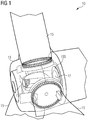
Fig. 1 illustrates in a partial schematic form awind turbine 10. The wind turbine comprises ahub 13 to whichplural rotor blades 15 are connected. The hub is mechanically connected to amain shaft 17 whose rotation is transformed by an optional gear box to a rotation of a secondary shaft, wherein the gear box may be optional in which case the wind turbine may be a direct drive wind turbine (as shown infig. 1 ). Themain shaft 17 or the secondary shaft drives aelectric generator 100 which may be in particular a synchronous permanent magnet generator providing a power stream to a converter (not shown in the attached figures) for transforming a variable AC power stream from theelectric generator 100 to a fixed frequency AC power stream which is to be provided to an utility grid (not shown in the attached figures), which is connected to the converter. -
Fig. 2 schematically illustrates in more detail thegenerator 100, which includes astator 105 and arotor 106 externally arranged with respect to thestator 105. According to other embodiments of the present invention (not shown) the rotor may be internally arranged with respect to thestator 105. Therotor 106 rotates around a rotation axis also defining the axial direction X of thegenerator 100. Perpendicular to the axial direction X a radial direction Y and a tangential direction Z are defined. Thestator 105 is arranged around the rotation axis X and comprises a not illustrated stator yoke having teeth and slots which are spaced apart in the tangential direction Z Around the teeth, plural not illustrated conductor windings are arranged. Therotor 106 is fixedly connected to the main shaft 107 by means of arotary bearing 108, which has astationary ring 109 fixed to thestator 105 and a rotary ring (not represented) fixed to therotor 106 themain shaft 17. In the embodiment of the attachedfigure 2 , where therotor 106 is externally arranged with respect to thestator 105, thestationary ring 109 is an inner ring of the rotary bearing 108 of theelectric generator 100. Anaccelerometer 111 is fixed and mounted at any position on thestationary ring 109. Theaccelerometer 111 may be mounted for measurement of avibration signal 202. Theaccelerometer 111 may be mounted for measurement of avibration signal 202 in the tangential direction Z. According to another embodiment of the present invention, theaccelerometer 111 may be mounted for measurement of a vibration signal in the radial direction Y. According to other embodiments of the present invention, theaccelerometer 111 may be mounted on other locations on thestator 105, for example on the stator plates, which are normally provided at axial ends of thestator 105. - The
electric generator 100 typically shows a cogging torque Tcog, which varies periodically within a mechanical period:
stator 105, k is an integer varying between 1 and infinite, Tk a plurality of constants depending on the geometry of therotor 106 and thestator 105 and θ is the rotor mechanical position. The cogging torque Tcog results from the airgap reluctance variation with rotor position, in other words from the interaction between magnets and stator teeth (when thestator 105 is unexcited). Thevibration signal 202 is used according to the present invention as an input signal, which is a good representation of the cogging torque Tcog. This was confirmed by experimental observation. -
Fig. 3 schematically illustrates a possible implementation of a hardware orlogical circuit 200 and of a method for calculating position and/or speed of the rotor 103. Thecircuit 200 comprises aninput port 201 for receiving thevibration input signal 202, measured by theaccelerometer 111. Thecircuit 200 further includes a band-pass filter 205 connected to theinput port 201 and receiving thevibration input signal 202 for generating as output a vibration filteredsignal 203 at the frequency range of interest. The vibration filteredsignal 203 is provided as input to aspeed observer module 210 for generating as outputs a cogging position signal 214 and acogging frequency signal 215. According to embodiments of the present invention, thespeed observer module 210 may be a phase-locked loop (PLL). According to other embodiments of the present invention, another suitable circuit may be selected for calculating the cogging position signal 214 and thecogging frequency signal 215. The vibration filteredsignal 203 is further provided to aphase shifter 207 receiving as further input thecogging frequency signal 215. Thephase shifter 207 generates as output a phase shifted vibration signal 204.Thespeed observer module 210 comprises twoinput ports signal 203 and the shiftedvibration signal 204. The shiftedvibration signal 204 is shifted of 90° with respect to the vibration filteredsignal 203. Alternatively, According to other embodiments of the present invention, thephase shifter 207 is not present and only the vibration filteredsignal 203 is provided as input to thespeed observer module 210. Thecircuit 200 further includes arotor speed module 220 receiving the cogging position signal 214 and thecogging frequency signal 215 as inputs and generating a rotor position signal 221 and arotor speed signal 222 as outputs. After obtaining the cogging position signal 214 and thecogging frequency signal 215, these are scaled in therotor speed module 220 accordingly. A position offset may be added. The parameters for the operational steps to be performed in therotor speed module 220 may be obtained by means of FEM simulation or experiments. - A comparison of
experimental results 322 of the speed of therotor 106 with therotor speed signal 222 is shown in the diagram 300 ofFig. 4 . It becomes evident that the present invention efficiently permits to substitute a directly measured speed of therotor 106 with the estimatedrotor speed signal 222. The same applies to the position of therotor 106. - The
logical circuit 200 may be activated when theelectric generator 100 is in open circuit, i.e. when theelectric generator 100 is below the so-called "cut-in speed" and the converter is switched off. Thelogical circuit 200 may be activated at the time when the connection between theelectric generator 100 and the converter is required, i.e. at the cut-in speed or immediately before the "cut-in speed" is reached. - It should be noted that the term "comprising" does not exclude other elements or steps and "a" or "an" does not exclude a plurality. Also elements described in association with different embodiments may be combined. It should also be noted that reference signs in the claims should not be construed as limiting the scope of the claims.
Claims (10)
- A circuit (200) for calculating position and/or speed of a rotor (103) of an electric generator (100), the circuit (200) comprising:an input port (201) for receiving a vibration input signal (202) representing a cogging torque of the electric generator (100),a speed observer module (210) connected to the input port (201) and generating a cogging position signal (214) and a cogging frequency signal (215) as outputs,a rotor speed module (220) receiving the cogging position signal (214) and the cogging frequency signal (215) as inputs and generating a rotor position signal (221) and a rotor speed signal (222) as outputs.
- The circuit (200) according to claim 1, wherein the circuit (200) further includes a band-pass filter (205) connected between the input port (201) and the speed observer module (210).
- The circuit (200) according to claim 1 or 2, wherein the speed observer module (210) is a phase-locked loop circuit module and the circuit (200) further includes a phase shifter (207) connected between the band-pass filter (205) and the speed observer module (210), the phase shifter (207) receiving as input the cogging frequency signal (215), the speed observer module (210) comprising two input ports (208, 209) respectively connected to the phase shifter (207) and the band-pass filter (205).
- A wind turbine (10) comprising an electric generator (100) and a circuit (200) according to any of the previous claims.
- A wind turbine (10) according to claim 4, wherein the wind turbine (10) includes an accelerometer (111) fixed with respect to a stator (105) of the electric generator (100), the accelerometer generating the vibration input signal (202).
- A wind turbine (10) according to claim 5, wherein the accelerometer (111) is fixed to a stationary ring (109) of rotary bearing (108) of the electric generator (100).
- A method of calculating position and/or speed of a rotor (103) of an electric generator (100), the method comprising:deriving a cogging torque signal of the electric generator (100) from an acceleration input signal (202),generating a cogging position signal (214) and a cogging frequency signal (215) based on the cogging torque signal,scaling and/or off-setting the cogging position signal (214) and the cogging frequency signal (215) for generating a rotor position signal (221) and a rotor speed signal (222).
- The method according to claim 7 wherein the cogging position signal (214) and the cogging frequency signal (215) are generated in a phase-locked loop circuit (210) receiving as input a filtered vibration input signal (203) and a second signal (204) having a phase shift with respect to the filtered vibration input signal (203).
- The method according to claim 8, wherein the second signal (204) has a phase shift of 90° with respect to the filtered vibration input signal (203).
- The method according to any of the claims 7 to 9, wherein the method activated when the electric generator (100) is in open circuit.
Priority Applications (3)
| Application Number | Priority Date | Filing Date | Title |
|---|---|---|---|
| EP19172847.6A EP3736970A1 (en) | 2019-05-06 | 2019-05-06 | Position and speed calculation for an electric generator |
| US16/867,122 US20200358384A1 (en) | 2019-05-06 | 2020-05-05 | Position and speed calculation for an electric generator |
| CN202010372296.5A CN111894805B (en) | 2019-05-06 | 2020-05-06 | Position and speed calculation for generator |
Applications Claiming Priority (1)
| Application Number | Priority Date | Filing Date | Title |
|---|---|---|---|
| EP19172847.6A EP3736970A1 (en) | 2019-05-06 | 2019-05-06 | Position and speed calculation for an electric generator |
Publications (1)
| Publication Number | Publication Date |
|---|---|
| EP3736970A1 true EP3736970A1 (en) | 2020-11-11 |
Family
ID=66439906
Family Applications (1)
| Application Number | Title | Priority Date | Filing Date |
|---|---|---|---|
| EP19172847.6A Withdrawn EP3736970A1 (en) | 2019-05-06 | 2019-05-06 | Position and speed calculation for an electric generator |
Country Status (3)
| Country | Link |
|---|---|
| US (1) | US20200358384A1 (en) |
| EP (1) | EP3736970A1 (en) |
| CN (1) | CN111894805B (en) |
Family Cites Families (3)
| Publication number | Priority date | Publication date | Assignee | Title |
|---|---|---|---|---|
| CN101388639B (en) * | 2008-11-03 | 2010-10-13 | 北京清能华福风电技术有限公司 | Non-position sensor vector control method for double-feed wind power generator |
| US9966889B2 (en) * | 2013-05-12 | 2018-05-08 | Infineon Technologies Ag | Optimized control for synchronous motors |
| CN104865400B (en) * | 2015-04-14 | 2018-08-28 | 华北电力大学 | A kind of detection recognition method and system of Wind turbines rotating speed |
-
2019
- 2019-05-06 EP EP19172847.6A patent/EP3736970A1/en not_active Withdrawn
-
2020
- 2020-05-05 US US16/867,122 patent/US20200358384A1/en not_active Abandoned
- 2020-05-06 CN CN202010372296.5A patent/CN111894805B/en active Active
Non-Patent Citations (4)
| Title |
|---|
| BECCUE P B ET AL: "A Coupled Piezoelectric/Single-Hall-Sensor Position Observer for Permanent Magnet Synchronous Machines", IEEE TRANSACTIONS ON INDUSTRIAL ELECTRONICS, IEEE SERVICE CENTER, PISCATAWAY, NJ, USA, vol. 54, no. 5, 1 October 2007 (2007-10-01), pages 2389 - 2397, XP011189308, ISSN: 0278-0046, DOI: 10.1109/TIE.2007.900323 * |
| GALFARSORO UNAI ET AL: "Analysis of vibration induced by cogging torque in permanent-magnet synchronous motors", 2017 IEEE INTERNATIONAL WORKSHOP OF ELECTRONICS, CONTROL, MEASUREMENT, SIGNALS AND THEIR APPLICATION TO MECHATRONICS (ECMSM), IEEE, 24 May 2017 (2017-05-24), pages 1 - 6, XP033105821, DOI: 10.1109/ECMSM.2017.7945882 * |
| LING LUO ET AL: "Verification of permanent magnet synchronous generator for stand-alone wind power", ELECTRICAL MACHINES AND SYSTEMS (ICEMS), 2011 INTERNATIONAL CONFERENCE ON, IEEE, 20 August 2011 (2011-08-20), pages 1 - 4, XP032020180, ISBN: 978-1-4577-1044-5, DOI: 10.1109/ICEMS.2011.6073418 * |
| RISHABH SINGH: "Novel Rotor Position Estimation Technique For Switched Reluctance Motor Using Vibration Signature Analysis", 1 January 2015 (2015-01-01), XP055627736, Retrieved from the Internet <URL:https://pdfs.semanticscholar.org/b1ea/fddaff9ddbbd38a315fa528222e6a7cee288.pdf> [retrieved on 20191001] * |
Also Published As
| Publication number | Publication date |
|---|---|
| CN111894805B (en) | 2024-03-19 |
| US20200358384A1 (en) | 2020-11-12 |
| CN111894805A (en) | 2020-11-06 |
Similar Documents
| Publication | Publication Date | Title |
|---|---|---|
| EP3454469B1 (en) | Torque ripple reduction for a generator and wind turbine including the same | |
| US8653797B2 (en) | Synchronous electrical machine | |
| US10042011B2 (en) | Method to detect or monitor the demagnetization of a magnet | |
| Baszynski et al. | A novel speed measurement method for a high-speed BLDC motor based on the signals from the rotor position sensor | |
| EP3264593B1 (en) | Control arrangement for a generator | |
| US10100811B2 (en) | Noise control for a wind turbine | |
| KR100790914B1 (en) | Method and apparatus for actively reducing torque irregularities in rotating electromagnetic devices | |
| EP2001121A2 (en) | Engine start system with quadrature AC excitation | |
| EP2001109A2 (en) | Generator with quadrature AC excitation | |
| US8097968B2 (en) | Position-controlled start from the AC line using a synchronous machine | |
| EP2592728B1 (en) | Electromagnetic device | |
| US9337765B2 (en) | Method for operating an electrical machine | |
| CN111894805B (en) | Position and speed calculation for generator | |
| EP3220536B1 (en) | Rotor synchronization of cross-compound systems on turning gear | |
| KR20200104396A (en) | How to control a synchronous double stator electric machine | |
| US8908336B2 (en) | Fault tolerant electrical machine | |
| US12445023B2 (en) | Magnetic gap length estimating device, magnetic gap length estimating method, and driving device for rotating electric machine | |
| Mekala et al. | Vibration and noise analysis of 4Ф switched reluctance motor drive | |
| Tozune et al. | Improvement of torque-speed characteristics of brushless motor by automatic lead angle adjustment | |
| JP4745838B2 (en) | Control method and apparatus for electric actuator | |
| US11927102B2 (en) | Main engine start using a dual permanent magnet generator system | |
| US12603591B2 (en) | Method for controlling an electrical generator of a wind turbine | |
| CN115208262B (en) | Motor control device and motor control method | |
| JP2007259559A (en) | Rotation speed detector | |
| Gkiolekas et al. | Fault Impact on Dual-Rotor Surface Permanent Magnet Synchronous Generator via the Finite Element Method |
Legal Events
| Date | Code | Title | Description |
|---|---|---|---|
| PUAI | Public reference made under article 153(3) epc to a published international application that has entered the european phase |
Free format text: ORIGINAL CODE: 0009012 |
|
| STAA | Information on the status of an ep patent application or granted ep patent |
Free format text: STATUS: THE APPLICATION HAS BEEN PUBLISHED |
|
| AK | Designated contracting states |
Kind code of ref document: A1 Designated state(s): AL AT BE BG CH CY CZ DE DK EE ES FI FR GB GR HR HU IE IS IT LI LT LU LV MC MK MT NL NO PL PT RO RS SE SI SK SM TR |
|
| AX | Request for extension of the european patent |
Extension state: BA ME |
|
| STAA | Information on the status of an ep patent application or granted ep patent |
Free format text: STATUS: REQUEST FOR EXAMINATION WAS MADE |
|
| 17P | Request for examination filed |
Effective date: 20210105 |
|
| RBV | Designated contracting states (corrected) |
Designated state(s): AL AT BE BG CH CY CZ DE DK EE ES FI FR GB GR HR HU IE IS IT LI LT LU LV MC MK MT NL NO PL PT RO RS SE SI SK SM TR |
|
| STAA | Information on the status of an ep patent application or granted ep patent |
Free format text: STATUS: EXAMINATION IS IN PROGRESS |
|
| 17Q | First examination report despatched |
Effective date: 20210812 |
|
| STAA | Information on the status of an ep patent application or granted ep patent |
Free format text: STATUS: THE APPLICATION IS DEEMED TO BE WITHDRAWN |
|
| 18D | Application deemed to be withdrawn |
Effective date: 20211223 |