EP3736966A1 - Rotary electric machine device - Google Patents
Rotary electric machine device Download PDFInfo
- Publication number
- EP3736966A1 EP3736966A1 EP18898520.4A EP18898520A EP3736966A1 EP 3736966 A1 EP3736966 A1 EP 3736966A1 EP 18898520 A EP18898520 A EP 18898520A EP 3736966 A1 EP3736966 A1 EP 3736966A1
- Authority
- EP
- European Patent Office
- Prior art keywords
- power source
- switching mechanism
- electric machine
- connection
- rotary electric
- Prior art date
- Legal status (The legal status is an assumption and is not a legal conclusion. Google has not performed a legal analysis and makes no representation as to the accuracy of the status listed.)
- Granted
Links
Images


Classifications
-
- H—ELECTRICITY
- H02—GENERATION; CONVERSION OR DISTRIBUTION OF ELECTRIC POWER
- H02P—CONTROL OR REGULATION OF ELECTRIC MOTORS, ELECTRIC GENERATORS OR DYNAMO-ELECTRIC CONVERTERS; CONTROLLING TRANSFORMERS, REACTORS OR CHOKE COILS
- H02P25/00—Arrangements or methods for the control of AC motors characterised by the kind of AC motor or by structural details
- H02P25/16—Arrangements or methods for the control of AC motors characterised by the kind of AC motor or by structural details characterised by the circuit arrangement or by the kind of wiring
- H02P25/18—Arrangements or methods for the control of AC motors characterised by the kind of AC motor or by structural details characterised by the circuit arrangement or by the kind of wiring with arrangements for switching the windings, e.g. with mechanical switches or relays
-
- H—ELECTRICITY
- H02—GENERATION; CONVERSION OR DISTRIBUTION OF ELECTRIC POWER
- H02P—CONTROL OR REGULATION OF ELECTRIC MOTORS, ELECTRIC GENERATORS OR DYNAMO-ELECTRIC CONVERTERS; CONTROLLING TRANSFORMERS, REACTORS OR CHOKE COILS
- H02P25/00—Arrangements or methods for the control of AC motors characterised by the kind of AC motor or by structural details
- H02P25/16—Arrangements or methods for the control of AC motors characterised by the kind of AC motor or by structural details characterised by the circuit arrangement or by the kind of wiring
- H02P25/18—Arrangements or methods for the control of AC motors characterised by the kind of AC motor or by structural details characterised by the circuit arrangement or by the kind of wiring with arrangements for switching the windings, e.g. with mechanical switches or relays
- H02P25/184—Arrangements or methods for the control of AC motors characterised by the kind of AC motor or by structural details characterised by the circuit arrangement or by the kind of wiring with arrangements for switching the windings, e.g. with mechanical switches or relays wherein the motor speed is changed by switching from a delta to a star, e.g. wye, connection of its windings, or vice versa
-
- H—ELECTRICITY
- H02—GENERATION; CONVERSION OR DISTRIBUTION OF ELECTRIC POWER
- H02P—CONTROL OR REGULATION OF ELECTRIC MOTORS, ELECTRIC GENERATORS OR DYNAMO-ELECTRIC CONVERTERS; CONTROLLING TRANSFORMERS, REACTORS OR CHOKE COILS
- H02P25/00—Arrangements or methods for the control of AC motors characterised by the kind of AC motor or by structural details
- H02P25/16—Arrangements or methods for the control of AC motors characterised by the kind of AC motor or by structural details characterised by the circuit arrangement or by the kind of wiring
- H02P25/22—Multiple windings; Windings for more than three phases
-
- H—ELECTRICITY
- H02—GENERATION; CONVERSION OR DISTRIBUTION OF ELECTRIC POWER
- H02P—CONTROL OR REGULATION OF ELECTRIC MOTORS, ELECTRIC GENERATORS OR DYNAMO-ELECTRIC CONVERTERS; CONTROLLING TRANSFORMERS, REACTORS OR CHOKE COILS
- H02P4/00—Arrangements specially adapted for regulating or controlling the speed or torque of electric motors that can be connected to two or more different electric power supplies
-
- B—PERFORMING OPERATIONS; TRANSPORTING
- B62—LAND VEHICLES FOR TRAVELLING OTHERWISE THAN ON RAILS
- B62D—MOTOR VEHICLES; TRAILERS
- B62D5/00—Power-assisted or power-driven steering
- B62D5/04—Power-assisted or power-driven steering electrical, e.g. using an electric servo-motor connected to, or forming part of, the steering gear
Definitions
- the first power source connection terminal 6a is a connection terminal to which the first DC power source 5a is connected.
- the second power source connection terminal 6b is a connection terminal to which the second DC power source 5b whose voltage is lower than the first DC power source 5a is connected.
- the first and the second DC power sources 5a, 5b are provided outside the rotary electric machine apparatus 1.
- the first DC power source 5a is a DC power source of 48V, for example, and is a high voltage battery, such as a lithium ion secondary battery, or a DC voltage obtained by stepping down or stepping up an output voltage of a battery.
- the second DC power source 5b is a lead battery of 12V, for example.
- the rotary electric machine body 2 is provided with plural-phase windings 14.
- the rotary electric machine body 2 is provided with three-phase windings Cu, Cv, Cw of U phase, V phase, and W phase, as the plural-phase windings 14.
- the rotary electric machine body 2 is a permanent magnet synchronous rotary electric machine whose stator is provided with three-phase-windings Cu, Cv, Cw, and whose rotor is provided with the permanent magnet.
- the controller 25 moves each movable contact 245 by changing the conduction state to each coil 246, and switches the first winding connection state (Y connection) in which each movable contact 245 connects between the first input terminal 241 and the output terminal 243, and the second winding connection state ( ⁇ connection) in which each movable contact 245 connects between the second input terminal 242 and the output terminal 243.
- a shunt resistance 123 as a current sensor 123 is connected in series to the series circuit of each phase. A both ends potential difference of each shunt resistance 123 is inputted into the input circuit 9 of the controller 25 as an output signal of the current sensor 123 (unillustrated).
- the gate terminal of each switching device is connected to the output circuit 11 of the controller 25. Therefore, each switching device is turned on or turned off by the control signal outputted from the output circuit 11 of the controller 25.
- a power source voltage sensor for detecting the DC voltage supplied to the inverter 12 is provided, and an output signal of the power source voltage sensor is inputted into the input circuit 9 of the controller 25 (unillustrated).
- an induced voltage Ve[V] generated in windings becomes a value obtained by multiplying the rotational speed ⁇ [rad/s] of the rotor to the induced voltage constant Ke [V ⁇ s/rad].
- Ve Ke ⁇ ⁇
- the induced voltage constant Ke is proportional to the torque constant Kt, a current I required for generating the same torque T can be small as the induced voltage constant Ke becomes large. Therefore, as the induced voltage constant Ke becomes large, it is advantageous for suppressing unnecessary heat generation of apparatus and improving reliability of apparatus.
- the controller 25 when switching the power source switching mechanism 23 to the first power source connection terminal 6a side connection of high voltage, the controller 25 switches the winding connection switching mechanism 24 so that the three-phase windings become the first winding connection state (in this example, Y connection) of high induced voltage constant.
- the controller 25 switches the winding connection switching mechanism 24 so that the three-phase windings becomes the second winding connection state (in this example, ⁇ connection) of low induced voltage constant.
- the controller 25 detects the rotational angle speed and the rotational angle (magnetic pole position) of the rotor based on the output signal of the rotation speed sensor 13, and detects the currents which flow into the three-phase windings based on the output signal of the current sensor 123, and detects the DC voltage supplied to the inverter 12 based on the output signal of the voltage sensor.
- the controller 25 performs PWM (Pulse Width Modulation) control that controls on/off each switching device based on the voltage commands of the three-phase windings, and the switching state (DC voltage) of the power source switching mechanism 23.
- the controller 25 compares the voltage command of each phase with a carrier wave (triangular wave) which oscillates with an amplitude of the DC voltage, generates an on/off control signal of each phase based on the comparison result, and outputs it to the gate terminal of corresponding switching device.
- PWM Pulse Width Modulation
- a motion of the rack shaft 20 transmits to the front wheels 18a, 18b through the tie rods 21a, 21b and the steering knuckle arms 19a, 19b, and the front wheels 18a, 18b are steered.
- the rotary electric machine apparatus 1 which is a steering motor is attached to the rack shaft 20, and the output torque of the rotary electric machine apparatus 1 is a power to move the rack shaft 20.
- the rotary electric machine apparatus 1 controls the output torque of the rotary electric machine based on the output signal of the steering sensor 17 and the vehicle signal such as the vehicle speed, and steering according to driver operation is performed.
- the rotary electric machine apparatus 1 is provided with the first set of controller 25a which controls the first set of inverter 12a and the first set of winding connection switching mechanism 24a, and the second set of controller 25b which controls the second set of inverter 12b and the second set of winding connection switching mechanism 24b.
- the first set of controller 25a is provided with a first set of arithmetic processor 10a, a first set of storage apparatus 33a, a first set of input circuit 9a, a first set of output circuit 11a, and a first set of power supply circuit 8a.
- the second set of controller 25b is provided with a second set of arithmetic processor 10b, a second set of storage apparatus 33b, a second set of input circuit 9b, a second set of output circuit 11b, and a second set of power supply circuit 8b.
- the first set of controller 25a and the second set of controller 25b communicate to each other via a communication line. Since the basic configuration of each set of controllers 25a, 25b is the same as that of the controller 25 of Embodiment 1, explanation is omitted.
- the first set of controller 25a and the second set of controller 25b are communicating mutually, and determine whether abnormality occurred in the other side. When abnormality does not occur in both of the first set and the second set of controllers 25a, 25b, the controller of a predetermined set switches the power source switching mechanism 23.
- the second set of controller 25b detects the rotational speed and the rotational angle (magnetic pole position) of the rotor based on the output signal of the second set of rotation sensor 13b, detects currents which flows into the second set of three-phase windings based on the output signal of the second set of current sensor 123, and detects the DC voltage supplied to the second set of inverter 12b based on the output signal of the second set of voltage sensor.
- the driving force of the rotary electric machine body 2 is the driving force source of the steering device of vehicle, and the rotary electric machine apparatus 1 is built into the electric power steering apparatus.
- the first set of steering sensor 17a and the second set of steering sensor 17b which detect one or both of a steering angle and a steering wheel torque of driver are attached to the steering shaft 16.
- the other DC power source when one DC power source has abnormality, the other DC power source can be used and the rotary electric machine apparatus 1 can be operated. And, even if the DC power source is switched to the high voltage or the low voltage, the induced voltage constant of each set windings can be switched appropriately and the rotary electric machine can be operated well. Since 2 sets of the three-phase windings, the winding connection switching mechanisms, the inverters, the controllers, and the like are provided and duplicated, even if abnormality occurs in one set, in the state where the induced voltage constant of the windings of the other set is switched appropriately, the rotary electric machine can output torque by the windings of the other set. Therefore, the function of the rotary electric machine is not lost completely and the reliability of apparatus can be improved more.
Landscapes
- Engineering & Computer Science (AREA)
- Power Engineering (AREA)
- Control Of Ac Motors In General (AREA)
- Inverter Devices (AREA)
Abstract
Description
- The present disclosure is related to a rotary electric machine apparatus using two DC power sources with different voltages.
- About the above rotary electric machine apparatus, for example, the technology described in
PLT 1 is known. In the technology ofPLT first stator windings 14, the first inverter INV1 for thefirst stator windings 14, thesecond stator windings 16, and the second inverter INV2 for thesecond stator windings 16 are provided. The DC power of thesecond battery 22 of high voltage is supplied to the second inverter INV2. The switch is switched so that the DC power of thefirst battery 20 of low voltage is supplied to the first inverter INV1 in low rotational speed, and the DC power of thesecond battery 22 of high voltage is supplied to the first inverter INV1 in high rotational speed. The first and thesecond stator windings - PLT 1:
JP 2013-219868 A - However, in the technology of
PLT 1, when thesecond battery 22 of high voltage is failed, since the DC power is not supplied to the second inverter INV2 and thesecond stator windings 16, the output of the rotary electric machine drops. When thesecond battery 22 of high voltage is failed, if the switch is switched in high rotational speed so that the DC power of thesecond battery 22 of high voltage is supplied to the first inverter INV1, the DC power is no longer supplied to the first inverter INV1 and thefirst stator windings 14, and the output of the rotary electric machine becomes zero. - On the other hand, when the
first battery 20 of low voltage is failed, if the switch is switched in low rotational speed so that the DC power of thefirst battery 20 is supplied to the first inverter INV1, the DC power is no longer supplied to the first inverter INV1 and thefirst stator windings 14, and the output of the rotary electric machine drops. Therefore, in the technology ofPLT 1, when failure occurred in one DC power source, there is a problem that the output of the rotary electric machine drops. - In the technology of
PLT 1, since thefirst stator windings 14 is fixed to Y connection, the induced voltage constant of thefirst stator windings 14 is a fixed value. Accordingly, in the technology ofPLT 1, in low rotational speed in which the induced voltage generated in thefirst stator windings 14 becomes low, the DC power of thefirst battery 20 of low voltage is supplied correspondingly. And, in high rotational speed in which the induced voltage generated in thefirst stator windings 14 becomes high, the DC power of thesecond battery 22 of high voltage is supplied correspondingly. However, as mentioned above, when failure occurred in the first or the second battery, the power source voltage is no longer changed in accordance with the induced voltage which changes according to rotational speed, there is a problem that the performance of the rotary electric machine drops. - Thus, it is desirable to provide a rotary electric machine apparatus which can make the rotary electric machine output torque, and can change characteristics of a rotary electric machine according to change of the DC power voltage, even if failure occurs in one DC power source.
- A rotary electric machine apparatus according to the present disclosure including:
- a first power source connection terminal to which a first DC power source is connected;
- a second power source connection terminal to which a second DC power source whose voltage is lower than the first DC power source is connected;
- a power source switching mechanism that switches between a DC power supplied to the first power source connection terminal and a DC power supplied to the second power source connection terminal, and outputs;
- a rotary electric machine body having plural-phase windings;
- a winding connection switching mechanism that switches interconnection of the plural-phase windings between a first winding connection state, and a second winding connection state in which an induced voltage constant of windings becomes lower than the first winding connection state;
- an inverter that is provided with switching devices , and converts a DC power outputted from the power source switching mechanism and an AC power supplied to the plural-phase windings; and
- a controller that switches the power source switching mechanism, switches the winding connection switching mechanism according to a switching state of the power source switching mechanism, and drives on/off the switching devices to control the rotary electric machine body based on the switching state of the power source switching mechanism and a switching state of the winding connection switching mechanism.
- According to the rotary electric machine apparatus of the present disclosure, since the power source switching mechanism is switched to the state where the DC power of the first DC power source of high voltage is outputted, or the state where the DC power of the second DC power source of low voltage is outputted, for example, when abnormality occurs in one DC power source, the rotary electric machine apparatus can be operated using the other DC power source. Then, since the winding connection switching mechanism is switched to the first winding connection state where the induced voltage constant of windings is high, or the second winding connection state where the induced voltage constant of windings is low, according to the switching state of the power source switching mechanism, the induced voltage constant of windings can be changed appropriately according to change of the DC voltage. Then, according to change of the DC voltage and change of the induced voltage constant of windings, the switching devices of the inverter is controlled on/off appropriately, and the rotary electric machine body can be controlled. Therefore, even if failure occurs in one DC power source, the rotary electric machine can output torque, and characteristics of the rotary electric machine can be changed appropriately according to change of the DC power voltage.
-
-
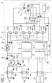
FIG. 1 is a circuit diagram of the rotary electric machine apparatus according toEmbodiment 1; -
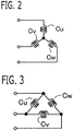
FIG. 2 is a figure showing Y connection of the three-phase windings according toEmbodiment 1; -
FIG. 3 is a figure showing Δ connection of the three-phase windings according toEmbodiment 1; -
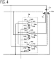
FIG. 4 is a circuit diagram of the winding connection switching mechanism according toEmbodiment 1; -
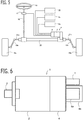
FIG. 5 is a schematic configuration diagram of the electric power steering apparatus according toEmbodiment 1; -
FIG. 6 is a side view of the rotary electric machine apparatus configured integrally according toEmbodiment 1; -
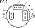
FIG. 7 is a side view of the rotary electric machine apparatus configured integrally according toEmbodiment 1; -
FIG. 8 is a circuit diagram of the rotary electric machine apparatus according toEmbodiment 2; -
FIG. 9 is a schematic configuration diagram of the electric power steering apparatus according toEmbodiment 2; -
FIG. 10 is a side view of the rotary electric machine apparatus configured integrally according toEmbodiment 2; and -
FIG. 11 is a side view of the rotary electric machine apparatus configured integrally according toEmbodiment 2. - A rotary
electric machine apparatus 1 according toEmbodiment 1 will be explained with reference to drawings.FIG. 1 is a circuit diagram of the rotaryelectric machine apparatus 1 according to the present embodiment. - The rotary
electric machine apparatus 1 is provided with a first powersource connection terminal 6a, a second powersource connection terminal 6b, a powersource switching mechanism 23, a rotaryelectric machine body 2, a windingconnection switching mechanism 24, aninverter 12, and acontroller 25. In the present embodiment, the rotaryelectric machine apparatus 1 is mounted on a vehicle. As described in detail later, a driving force of the rotaryelectric machine body 2 is a driving force source of a steering device of vehicle, and the rotaryelectric machine apparatus 1 constitutes an electric power steering apparatus. - The first power
source connection terminal 6a is a connection terminal to which the firstDC power source 5a is connected. The second powersource connection terminal 6b is a connection terminal to which the secondDC power source 5b whose voltage is lower than the firstDC power source 5a is connected. The first and the secondDC power sources electric machine apparatus 1. The firstDC power source 5a is a DC power source of 48V, for example, and is a high voltage battery, such as a lithium ion secondary battery, or a DC voltage obtained by stepping down or stepping up an output voltage of a battery. The secondDC power source 5b is a lead battery of 12V, for example. - Each of the first and the second power
source connection terminals source connection terminal 6a is connected to a positive electrode of the firstDC power source 5a, and the negative electrode side terminal of the first powersource connection terminal 6a is connected to a negative electrode of the firstDC power source 5a. The positive electrode side terminal of the second powersource connection terminal 6b is connected to a positive electrode of the secondDC power source 5b, and the negative electrode side terminal of the second powersource connection terminal 6b is connected to a negative electrode of the secondDC power source 5b. - The power
source switching mechanism 23 is a switching mechanism which switches between the DC power supplied to the first powersource connection terminal 6a from the firstDC power source 5a, and the DC power supplied to the second powersource connection terminal 6b from the secondDC power source 5b, and outputs it. The powersource switching mechanism 23 is provided with afirst input terminal 231, asecond input terminal 232, anoutput terminal 233, and adriving terminal 234 into which a control signal of thecontroller 25 is inputted. In the present embodiment, the powersource switching mechanism 23 is an electromagnetic switch, and is provided with amovable contact 235 and acoil 236 which drives themovable contact 235. One end of thecoil 236 is connected to the drivingterminal 234. The powersource switching mechanism 23 moves themovable contact 235, when thecontroller 25 changes the conduction state to thecoil 236. Accordingly, a first power source connection state in which themovable contact 235 connects thefirst input terminal 231 and theoutput terminal 233, and a second power source connection state in which themovable contact 235 connects thesecond input terminal 232 and theoutput terminal 233 are switched. The powersource switching mechanism 23 may be configured by combining a plurality of switching devices. - The
first input terminal 231 is connected to the positive electrode side terminal of the first powersource connection terminal 6a. The negative electrode side terminal of the first powersource connection terminal 6a is connected to the common ground. Thesecond input terminal 232 is connected to the positive electrode side terminal of the second powersource connection terminal 6b. The negative electrode side terminal of the second powersource connection terminal 6b is connected to the common ground. - The
output terminal 233 is connected to the positive pole wire of theinverter 12, and supplies DC power of the first or the second DC power source to theinverter 12. The negative pole wire of theinverter 12 is connected to the common ground. On a connection path between theoutput terminal 233 and the positive pole wire of theinverter 12, a lowpass filter circuit 30, a powersource relay circuit 31, and a smoothingcapacitor 32 are provided. Theoutput terminal 233 is connected also to apower supply circuit 8 of thecontroller 25, and supplies DC power of the first or the secondDC power sources controller 25. - The rotary
electric machine body 2 is provided with plural-phase windings 14. In the present embodiment, the rotaryelectric machine body 2 is provided with three-phase windings Cu, Cv, Cw of U phase, V phase, and W phase, as the plural-phase windings 14. The rotaryelectric machine body 2 is a permanent magnet synchronous rotary electric machine whose stator is provided with three-phase-windings Cu, Cv, Cw, and whose rotor is provided with the permanent magnet. - As shown in
FIG. 1 andFIG. 4 , one end of the winding Cu of U phase is connected to a connection point of two switching devices for U phase of theinverter 12 described below, and the other end of the winding Cu of U phase is connected to achangeover switch 24u of U phase of the windingconnection switching mechanism 24. One end of winding Cv of V phase is connected to a connection point of two switching devices for V phase of theinverter 12, and the other end of winding Cv of V phase is connected to achangeover switch 24v of V phase of the windingconnection switching mechanism 24. One end of winding Cw of W phase is connected to a connection point of two switching devices for W phase of theinverter 12, and the other end of winding Cw of W phase is connected to achangeover switch 24w of W phase of the windingconnection switching mechanism 24. - The rotary
electric machine body 2 is provided with arotation sensor 13, such as a resolver and a rotary encoder, for detecting a rotational angle (magnetic pole position) of the rotor. The output signal of therotation sensor 13 is inputted into theinput circuit 9 of thecontroller 25. - The winding
connection switching mechanism 24 is a switching mechanism that switches interconnection of the plural-phase windings 14 between a first winding connection state, and a second winding connection state in which an induced voltage constant of windings becomes lower than the first winding connection state. In the present embodiment, the windingconnection switching mechanism 24 is a switching mechanism which switches interconnection of the three-phase-windings Cu, Cv, Cw between Y connection as the first winding connection state, and Δ connection as the second winding connection state. - The Y connection becomes connection as shown in
FIG. 2 ; the other end of the winding Cu of U phase, the other end of winding Cv of V phase, and the other end of winding Cw of W phase are connected mutually; and one end of the winding Cu of U phase, one end of winding Cv of V phase, and one end of winding Cw of W phase are connected to the switching devices of corresponding phase, respectively. The Δ connection becomes connection as shown inFIG. 3 ; and the other end of winding Cu of U phase is connected to one end of winding Cv of V phase, the other end of winding Cv of V phase is connected to one end of winding Cw of W phase, and the other end of winding Cw of W phase is connected to one end of the winding Cu of U phase. One end of winding Cu of U phase, one end of winding Cv of V phase, and one end of winding Cw of W phase are connected to the switching devices of corresponding phase, respectively. - An induced voltage constant of the Y connection becomes √3 times (1.732 times) larger than an induced voltage constant of the Δ connection. The winding resistor between the lines of the Y connection becomes 3 times larger than the winding resistor between the lines of the Δ connection.
- As shown in
FIG. 1 andFIG. 4 , the windingconnection switching mechanism 24 has achangeover switch 24u of U phase, achangeover switch 24v of V phase, and achangeover switch 24w of W phase. Thechangeover switch first input terminal 241, asecond input terminal 242, anoutput terminal 243, and a driving terminal 244 into which the control signal of thecontroller 25 is inputted. In the present embodiment, the changeover switch of each phase is an electromagnetic switch, and is provided with amovable contact 245, and acoil 246 which drives themovable contact 245. One end of thecoil 246 is connected to the drivingterminal 244. The windingconnection switching mechanism 24 may be configured by combining a plurality of switching devices. - The
output terminal 243 of thechangeover switch 24u of U phase is connected to the other end of the winding Cu of U phase. Thesecond input terminal 242 of thechangeover switch 24u of U phase is connected to one end of winding Cv of V phase in order to form the Δ connection. In order to form the Y connection, thefirst input terminal 241 of thechangeover switch 24u of U phase, thefirst input terminal 241 of thechangeover switch 24v of V phase, and thefirst input terminal 241 of thechangeover switch 24w of W phase are connected mutually, and the other ends of three-phase-windings Cu, Cv, Cw are short-circuited mutually. - The
output terminal 243 of thechangeover switch 24v of V phase is connected to the other end of winding Cv of V phase. Thesecond input terminal 242 of thechangeover switch 24v of V phase is connected to one end of winding Cw of W phase in order to form the Δ connection. Theoutput terminal 243 of thechangeover switch 24w of W phase is connected to the other end of winding Cw of W phase. Thesecond input terminal 242 of thechangeover switch 24w of W phase is connected to one end of the winding Cu of U phase in order to form the Δ connection. - About each of the changeover switches 24u, 24v, 24w of U phase, V phase, and W phase, the
controller 25 moves eachmovable contact 245 by changing the conduction state to eachcoil 246, and switches the first winding connection state (Y connection) in which eachmovable contact 245 connects between thefirst input terminal 241 and theoutput terminal 243, and the second winding connection state (Δ connection) in which eachmovable contact 245 connects between thesecond input terminal 242 and theoutput terminal 243. - In the present embodiment, when energizing each
coil 246 at a middle Duty ratio (for example, 50%), themovable contacts 245 move to an intermediate position connected to neither thefirst input terminal 241 nor thesecond input terminal 242, and are in a neutral winding connection state. In this state, the other ends of three-phase windings Cu, Cv, Cw become in the open state, and current does not flow into the three-phase windings Cu, Cv, Cw, regardless of the on-off state of the switching devices of theinverter 12. - The
inverter 12 is a power converter that converts between the DC power outputted from the powersource switching mechanism 23 and the AC power supplied to the plural-phase windings 14 of the rotaryelectric machine body 2, and is provided with the switching devices. Theinverter 12 is provided with three sets of series circuits where the positive electrodeside switching device 121 connected to the positive pole wire and the negative electrodeside switching device 122 connected to the negative pole wire are connected in series, corresponding to respective phases of the three-phase windings. The positive pole wire is connected to the positive electrode terminal side of the DC power source (in this example, theoutput terminal 233 of the power source switching mechanism 23), and the negative pole wire is connected to the negative electrode terminal side of the DC power source (in this example, the common ground). The connection point of the twoswitching devices - A
shunt resistance 123 as acurrent sensor 123 is connected in series to the series circuit of each phase. A both ends potential difference of eachshunt resistance 123 is inputted into theinput circuit 9 of thecontroller 25 as an output signal of the current sensor 123 (unillustrated). The gate terminal of each switching device is connected to theoutput circuit 11 of thecontroller 25. Therefore, each switching device is turned on or turned off by the control signal outputted from theoutput circuit 11 of thecontroller 25. A power source voltage sensor for detecting the DC voltage supplied to theinverter 12 is provided, and an output signal of the power source voltage sensor is inputted into theinput circuit 9 of the controller 25 (unillustrated). - The
controller 25 controls the powersource switching mechanism 23, the windingconnection switching mechanism 24, and theinverter 12. Each control of thecontroller 25 is realized by processing circuits provided in thecontroller 25. Specifically, thecontroller 25 is provided with anarithmetic processors 10 such as CPU (Central Processing Unit),storage apparatuses 33, aninput circuit 9 which inputs external signals into thearithmetic processor 10, anoutput circuit 11 which outputs signals from thearithmetic processor 10 to the outside, and apower supply circuit 8 which supplies power to each part of thecontroller 25. - As the
arithmetic processor 10, ASIC (Application Specific Integrated Circuit), IC (Integrated Circuit), DSP (Digital Signal Processor), FPGA (Field Programmable Gate Array), various kinds of logical circuits, various kinds of signal processing circuits, and the like may be provided. As thearithmetic processor 10, a plurality of the same type ones or the different type ones may be provided, and each processing may be shared and executed. As thestorage apparatuses 33, a RAM (Random Access Memory) which can read data and write data from thearithmetic processor 10, a ROM (Read Only Memory) which can read data from thearithmetic processor 10, and the like are provided. Theinput circuit 9 is connected with various kinds of sensors and signal wires such as therotation sensor 13, thecurrent sensor 123, a power source voltage sensor (unillustrated), asteering sensor 17, and avehicle signal 22; and is provided with an A/D converter and the like for inputting signals of these sensors and signal wires into thearithmetic processor 10. Theoutput circuit 11 is connected with electric loads such as the gate terminals of respective switching devices of theinverter 12, the drivingterminals 234 of the powersource switching mechanism 23, the drivingterminals 244 of the windingconnection switching mechanism 24, and the powersource relay circuit 31; and is provided with driving circuits and the like for outputting control signals to these electric loads from thearithmetic processor 10. - The
arithmetic processor 10 runs software items (programs) stored in thestorage apparatus 33 and collaborates with other hardware devices in thecontroller 25, such as thestorage apparatus 33, theinput circuit 9, theoutput circuit 11, and thepower supply circuit 8, so that the respective controls of thecontroller 25 are realized. - If only one DC power source is used as a power source of the rotary
electric machine apparatus 1, when abnormality occur in one DC power source, operation of the rotary electric machine becomes impossible. Then, it is desirable to use two DC power sources as a power source of the rotaryelectric machine apparatus 1. However, when voltages of two DC power sources are different each other, if the induced voltage constant of windings is set in accordance with the DC power source with higher voltage, disadvantage occurs when using the DC power source with lower voltage. On the contrary, if the induced voltage constant of windings is set in accordance with the DC power source with lower voltage, disadvantage occurs when using the DC power source with higher voltage. Then, when switching and using two DC power sources, it is desirable to change the induced voltage constant of windings in accordance with the voltage of the switched DC power source. - The relationship between voltage of the DC power source and the induced voltage constant of windings will be explained in more detail below. As shown in a next equation, an induced voltage constant KeY (it is also called back electromotive force constant) of Y connection becomes √3 times (1. 732 times) larger than an induced voltage constant KeΔ of Δ connection. A winding resistor RY between the lines of Y connection becomes 3 times larger than a winding resistor RΔ between the lines of Δ connection.


- By the way, generally, as shown in a next equation, an induced voltage Ve[V] generated in windings becomes a value obtained by multiplying the rotational speed ω [rad/s] of the rotor to the induced voltage constant Ke [V·s/rad].

- As shown in a next equation, a current I [A] flowing through windings becomes a value obtained by dividing a value obtained by subtracting an induced voltage Ve [V] from an applied voltage Va [V] applied to windings, by a resistance R [Ω] of windings.

- As shown in a next equation, an output torque T [N·m] of the rotary
electric machine body 2 becomes a value obtained by multiplying the current I [A] flowing through windings to a torque constant Kt [N·m/A]. The induced voltage constant Ke is proportional to the torque constant Kt.

- Since the induced voltage constant Ke is proportional to the torque constant Kt, a current I required for generating the same torque T can be small as the induced voltage constant Ke becomes large. Therefore, as the induced voltage constant Ke becomes large, it is advantageous for suppressing unnecessary heat generation of apparatus and improving reliability of apparatus.
- On the other hand, in a certain rotational speed ω, an applied voltage Va required for flowing a certain current I through windings becomes large as the induced voltage constant Ke and the resistance R of windings become large. Accordingly, in the state where windings is set to Y connection and the induced voltage constant Ke and the resistance R of windings became large, when the power source voltage becomes low, an operating range (a combination range of rotational speed and torque) where equivalent current can be flowed becomes narrow, and the characteristics of the rotary electric machine is deteriorated.
- Then, even if it is configured that two DC power sources whose voltage are different each other are used selectively, and windings of fixed connection with a small induced voltage constant (for example, windings of Δ connection) is used in accordance with the DC power source with lower voltage, when operating using the DC power source with higher voltage, although the characteristics of the rotary electric machine is not deteriorated, current becomes large with respect to voltage, unnecessary heat generation of apparatus is caused, and reliability of apparatus is deteriorated. On the contrary, if windings of fixed connection with a large induced voltage constant (for example, windings of Y connection) is used in accordance with the DC power source with higher voltage, when operating using the DC power source with lower voltage and trying to output high torque, shortage of voltage occurs, and characteristics of the rotary electric machine is deteriorated. Therefore, it is desirable to switch to a winding connection which has an appropriate induced voltage constant, according to change of the DC power source.
- Then, in the present embodiment, the
controller 25 switches the powersource switching mechanism 23, switches the windingconnection switching mechanism 24 according to a switching state of the powersource switching mechanism 23, and drives on/off the switching devices of theinverter 12 to control the rotaryelectric machine body 2, based on the switching state of the powersource switching mechanism 23 and a switching state of the windingconnection switching mechanism 24. - According to this configuration, since the power
source switching mechanism 23 is switched to the first power source connection state where DC power of the firstDC power source 5a of high voltage is outputted, or the second power source connection state where DC power of the secondDC power source 5b of low voltage is outputted, for example, when abnormality is caused in one DC power source, the rotaryelectric machine apparatus 1 can be operated using the other DC power source. Then, since the windingconnection switching mechanism 24 is switched to the first winding connection state where the induced voltage constant of windings is high, or the second winding connection state where the induced voltage constant of windings is low, according to the switching state of the powersource switching mechanism 23, the induced voltage constant of windings can be changed appropriately according to change of the DC voltage. Then, according to change of the DC voltage, and change of the induced voltage constant of windings, the switching devices of theinverter 12 is controlled on/off appropriately, and the rotaryelectric machine body 2 can be controlled. - In the present embodiment, when switching the power
source switching mechanism 23 to the first powersource connection terminal 6a side connection of high voltage, thecontroller 25 switches the windingconnection switching mechanism 24 so that the three-phase windings become the first winding connection state (in this example, Y connection) of high induced voltage constant. On the other hand, when switching the powersource switching mechanism 23 to the second powersource connection terminal 6b side connection of low voltage, thecontroller 25 switches the windingconnection switching mechanism 24 so that the three-phase windings becomes the second winding connection state (in this example, Δ connection) of low induced voltage constant. - According to this configuration, since the induced voltage constant of windings is set to high when the first
DC power source 5a of high voltage is used, current required for generating the same torque can be lowered, heat generation of apparatus can be suppressed, and reliability of apparatus can be improved. On the other hand, since the induced voltage constant of windings is set to low when the secondDC power source 5b of low voltage is used, even when outputting high torque, occurrence of voltage shortage can be suppressed, and deterioration of characteristics of the rotary electric machine can be suppressed. Therefore, even if the DC power source is switched to the high voltage or the low voltage, the induced voltage constant of windings can be switched appropriately and the rotary electric machine can be operated well. - The
controller 25 switches the powersource switching mechanism 23 to the second power source connection state when determining that abnormality occurs in the firstDC power source 5a, and switches the powersource switching mechanism 23 to the first power source connection state when determining that abnormality occurs in the secondDC power source 5b. On the other hand, when determining that abnormality occurs in neither the first nor the secondDC power sources controller 25 switches the powersource switching mechanism 23 to an initial connection state which is preliminarily set to either one of the first power source connection state and the second power source connection state. - The
controller 25 switches the powersource switching mechanism 23 to the first power source connection state or the second power source connection state by turning on or off the control signal to the drivingterminals 234 of the powersource switching mechanism 23. Thecontroller 25 switches the windingconnection switching mechanism 24 to the first winding connection state or the second winding connection state by turning on or off the control signal to the drivingterminals 244 of the windingconnection switching mechanism 24. In the present embodiment, when determining that control system of the rotaryelectric machine apparatus 1 such as theinverter 12 failed, thecontroller 25 switches the windingconnection switching mechanism 24 to a neutral winding connection state which is not the first and the second winding connection states, by performing PWM (Pulse Width Modulation) drive of the control signal to the drivingterminal 244 of the windingconnection switching mechanism 24 at a middle Duty ratio (for example, 50%). Accordingly, occurrence of dynamic braking by short circuit of windings can be prevented. - The
controller 25 calculates a current command of three-phase windings based on the torque command, the rotational speed, the switching state (DC voltage) of the powersource switching mechanism 23, and the switching state of the windingconnection switching mechanism 24. In this case, since the current command corresponding to the same torque command changes according to change of the induced voltage constant of windings and change of the DC voltage, thecontroller 25 switches one or both of setting data and setting method which are used for calculation of the current command of three-phase windings based on the torque command, according to the switching state of the windingconnection switching mechanism 24 and the switching state of the powersource switching mechanism 23. - In the present embodiment, the
controller 25 calculates a torque command which assists a steering mechanism, based on a steering wheel torque which is detected based on the output signal of thesteering sensor 17, and the vehicle signal 22 (for example, vehicle speed). - The
controller 25 performs current feedback control that changes voltage commands applied to the three-phase windings so that the current detection values of three-phase windings approaches current commands of the three-phase windings. Setting of the current commands of the three-phase windings and the current feedback control are performed on a dq-axis rotating coordinate system. The dq-axis rotating system consists of a d-axis defined in the direction of the N pole (magnetic pole position) of the permanent magnet provided in the rotator and a q-axis defined in the direction advanced to d-axis by 90 degrees (n/2) in an electrical angle, and which is the two-axis rotating coordinate system which rotates synchronizing with rotation of the rotator in the electrical angle. - The
controller 25 detects the rotational angle speed and the rotational angle (magnetic pole position) of the rotor based on the output signal of therotation speed sensor 13, and detects the currents which flow into the three-phase windings based on the output signal of thecurrent sensor 123, and detects the DC voltage supplied to theinverter 12 based on the output signal of the voltage sensor. - The
controller 25 performs PWM (Pulse Width Modulation) control that controls on/off each switching device based on the voltage commands of the three-phase windings, and the switching state (DC voltage) of the powersource switching mechanism 23. Thecontroller 25 compares the voltage command of each phase with a carrier wave (triangular wave) which oscillates with an amplitude of the DC voltage, generates an on/off control signal of each phase based on the comparison result, and outputs it to the gate terminal of corresponding switching device. - As mentioned above, the driving force of the rotary
electric machine body 2 is the driving force source of the steering device of vehicle, and the rotaryelectric machine apparatus 1 is built into the electric power steering apparatus. As shown inFIG. 5 , ahandle 15 which a driver operates is connected with a steeringshaft 16. Thesteering sensor 17 which detects one or both of a steering angle and a steering wheel torque of driver is attached to the steeringshaft 16.Tie rods rack shaft 20 are connected tosteering knuckle arms front wheels rack shaft 20 transmits to thefront wheels tie rods steering knuckle arms front wheels electric machine apparatus 1 which is a steering motor is attached to therack shaft 20, and the output torque of the rotaryelectric machine apparatus 1 is a power to move therack shaft 20. The rotaryelectric machine apparatus 1 controls the output torque of the rotary electric machine based on the output signal of thesteering sensor 17 and the vehicle signal such as the vehicle speed, and steering according to driver operation is performed. - As shown in
FIG. 6 andFIG. 7 , the first powersource connection terminal 6a, the second powersource connection terminal 6b, the powersource switching mechanism 23, the rotaryelectric machine body 2, the windingconnection switching mechanism 24, theinverter 12, and thecontroller 25 are configured integrally.FIG. 6 is a side view of the rotaryelectric machine apparatus 1 configured integrally.FIG. 7 is a side view which observed the connection terminal side of the rotaryelectric machine apparatus 1. Anoutput shaft 3 to which the driving force of the rotor is outputted projects from the rotaryelectric machine body 2 to one side of the axial direction. Theoutput shaft 3 is connected to a power transfer mechanism such as therack shaft 20 by a gear mechanism and the like. In the other side of the axial direction of the rotaryelectric machine body 2, theinverter 12, thecontroller 25, the powersource switching mechanism 23, and thedriving apparatus 4 such as the windingconnection switching mechanism 24 are provided. The rotaryelectric machine body 2 and thedriving apparatus 4 are stored in a cylindrical case. The connector of the first powersource connection terminal 6a, the connector of the second powersource connection terminal 6b, and thesignal connector 7 for thesteering sensor 17 and thevehicle signal 22 project from the drivingapparatus 4 to the other side of the axial direction. - The rotary
electric machine apparatus 1 according toEmbodiment 2 will be explained. The explanation for constituent parts the same as those inEmbodiment 1 will be omitted. Although the basic configuration of the rotaryelectric machine apparatus 1 according to the present embodiment is the same as that ofEmbodiment 1, the present embodiment is different fromEmbodiment 1 in that 2 sets of the plural-phase windings, the winding connection switching mechanisms, and the inverters are provided. -
FIG. 8 is a circuit diagram of the rotaryelectric machine apparatus 1 according to the present embodiment. The first set of plural-phase windings 14a and the second set of plural-phase windings 14b are provided in the stator of the one rotaryelectric machine body 2. As similar toEmbodiment 1, the first set of plural-phase windings 14a is the three-phase windings Cua, Cva, Cwa, and the second set of plural-phase windings 14b is the three-phase windings Cub, Cvb, Cwb. - The rotary
electric machine apparatus 1 is provided with a first set of windingconnection switching mechanism 24a which switches interconnection of the first set of three phase windings between the first winding connection state and the second winding connection state, and a second set of windingconnection switching mechanism 24b which switches interconnection of the second set of three phase windings between the first winding connection state and the second winding connection state. As similar toEmbodiment 1, the first set of windingconnection switching mechanism 24a switches interconnection of the first set of three phase windings between the Y connection as the first winding connection state, and the Δ connection as the second winding connection state. The second set of windingconnection switching mechanism 24b switches interconnection of the second set of three phase windings between the Y connection as the first winding connection state, and the Δ connection as the second winding connection state. Since the basic configuration of the windingconnection switching mechanisms connection switching mechanism 24 ofEmbodiment 1, explanation is omitted. - The rotary
electric machine apparatus 1 is provided with a first set ofinverter 12a which converts power supplied to the first set of plural-phase windings 14a, and a second set ofinverter 12b which converts power supplied to the second set of plural-phase windings 14b. Since the inverter of each set is the same configuration as the inverter ofEmbodiment 1, explanation is omitted. - Only one power
source switching mechanism 23 is provided, and the DC power outputted from the powersource switching mechanism 23 is supplied in parallel to the first set and the second set ofinverters controllers source switching mechanism 23 is switched by the first set ofcontroller 25a or the second set ofcontroller 25b. - A driving terminal 234 (in this example, one end of the coil 236) of the power
source switching mechanism 23 is connected in parallel to anoutput circuit 11a of the first set ofcontroller 25a, and anoutput circuit 11b of the second set ofcontroller 25b. On a connection line between the drivingterminal 234 of the powersource switching mechanism 23 and the first set ofcontroller 25a, a first set ofrelay circuit 34a is provided, and turns on and off the connection between the drivingterminal 234 of the powersource switching mechanism 23 and the first set ofcontroller 25a. A driving terminal of the first set ofrelay circuit 34a is connected to theoutput circuit 11a of the first set ofcontroller 25a, and is turned on and off by the output signal of the first set ofcontroller 25a. Similarly, on a connection line between the drivingterminal 234 of the powersource switching mechanism 23 and the second set ofcontroller 25b, a second set ofrelay circuit 34b is provided, and turns on and off the connection between the drivingterminal 234 of the powersource switching mechanism 23 and the second set ofcontroller 25b. The driving terminal of the second set ofrelay circuit 34b is connected to theoutput circuit 11b of the second set ofcontroller 25b, and is turned on and off by the output signal of the second set ofcontroller 25b. The first set and the second set ofrelay circuits - The power
source switching mechanism 23 may also be duplicated. That is to say, a first set of power source switching mechanism which switches the DC power supplied to the first set ofinverter 12a and the first set ofcontroller 25a, and a second set of power source switching mechanism which switches the DC power supplied to the second set ofinverter 12b and the second set ofcontroller 25b may be provided. And, the power source switching mechanism of each set may be controlled by the controller of corresponding set. - On a connection path between the
output terminal 233 of the powersource switching mechanism 23 and a positive pole wire of the first set ofinverter 12a, a first set of lowpass filter circuit 30a, a first set of powersource relay circuit 31a, and a first set of smoothingcapacitor 32a are provided. On a connection path between theoutput terminal 233 of the powersource switching mechanism 23 and a positive pole wire of the second set ofinverter 12b, a second of lowpass filter circuit 30b, a second of powersource relay circuit 31b, and a second set of smoothingcapacitor 32b are provided. - Various kinds of sensors are also duplicated. For example, the rotary
electric machine apparatus 1 is provided with a first set ofrotation sensor 13a, a second set ofrotation sensor 13b, a first set ofcurrent sensor 123, a second set ofcurrent sensor 123, a first set of power source voltage sensor (unillustrated), and a second set of power source voltage sensor (unillustrated). An output signal of a first set ofsteering sensor 17a and an output signal of a second set ofsteering sensor 17b are inputted into the rotaryelectric machine apparatus 1. Avehicle signal 22a for first set and avehicle signal 22b for second set are inputted into the rotaryelectric machine apparatus 1. The output signals of the various sensors of each set are inputted into the controller of corresponding set. - The rotary
electric machine apparatus 1 is provided with the first set ofcontroller 25a which controls the first set ofinverter 12a and the first set of windingconnection switching mechanism 24a, and the second set ofcontroller 25b which controls the second set ofinverter 12b and the second set of windingconnection switching mechanism 24b. The first set ofcontroller 25a is provided with a first set ofarithmetic processor 10a, a first set ofstorage apparatus 33a, a first set ofinput circuit 9a, a first set ofoutput circuit 11a, and a first set ofpower supply circuit 8a. The second set ofcontroller 25b is provided with a second set ofarithmetic processor 10b, a second set ofstorage apparatus 33b, a second set ofinput circuit 9b, a second set ofoutput circuit 11b, and a second set ofpower supply circuit 8b. The first set ofcontroller 25a and the second set ofcontroller 25b communicate to each other via a communication line. Since the basic configuration of each set ofcontrollers controller 25 ofEmbodiment 1, explanation is omitted. - The first set and the second set of
controllers source switching mechanism 23. When abnormality occurs in the first set ofcontroller 25a, the second set ofcontroller 25b turns on the second set ofrelay circuit 34b, and switches the powersource switching mechanism 23, as similar toEmbodiment 1. When abnormality occurs in the first set ofcontroller 25a, the first set ofrelay circuit 34a is turned off. When abnormality occurs in the second set ofcontroller 25b, the first set ofcontroller 25a turns on the first set ofrelay circuit 34a, and switches the powersource switching mechanism 23, as similar toEmbodiment 1. When abnormality occurs in the second set ofcontroller 25b, the second set ofrelay circuit 34b is turned off. - The first set of
controller 25a and the second set ofcontroller 25b are communicating mutually, and determine whether abnormality occurred in the other side. When abnormality does not occur in both of the first set and the second set ofcontrollers source switching mechanism 23. - As similar to
Embodiment 1, the first set ofcontroller 25a switches the first set of windingconnection switching mechanism 24a so that the first set of three-phase windings becomes the first winding connection state (Y connection) or the second winding connection state (Δ connection), and drives on/off the switching devices of the first set ofinverter 12a based on the switching state of the powersource switching mechanism 23, and the switching state of the first set of three-phase windings in the first set of windingconnection switching mechanism 24a. - Similarly, the second set of
controller 25b switches the second set of windingconnection switching mechanism 24b so that the second set of three-phase windings become the first winding connection state (Y connection) or the second winding connection state (Δ connection), and drives on/off the switching devices of the second set ofinverter 12b based on the switching state of the powersource switching mechanism 23, and the switching state of the second set of three-phase windings in the second set of windingconnection switching mechanism 24b. - As similar to
Embodiment 1, when switching the powersource switching mechanism 23 to the first powersource connection terminal 6a side connection of high voltage, the first set ofcontroller 25a switches the first set of windingconnection switching mechanism 24a so that the first set of three-phase windings becomes the first winding connection state (Y connection). When switching the powersource switching mechanism 23 to the second powersource connection terminal 6b side connection of low voltage, the first set ofcontroller 25a switches the first set of windingconnection switching mechanism 24a so that the first set of three-phase windings becomes the second winding connection state (Δ connection). - As similar to
Embodiment 1, when switching the powersource switching mechanism 23 to the first powersource connection terminal 6a side connection of high voltage, the second set ofcontroller 25b switches the second set of windingconnection switching mechanism 24b so that the second set of three-phase windings becomes the first winding connection state (Y connection). When switching the powersource switching mechanism 23 to the second powersource connection terminal 6b side connection of low voltage, the second set ofcontroller 25b switches the second set of windingconnection switching mechanism 24b so that the second set of three-phase windings becomes the second winding connection state (Δ connection). - As similar to
Embodiment 1, the first set ofcontroller 25a calculates a current command of the first set of three-phase windings based on a first set of torque command, rotational speed, the switching state (DC voltage) of the powersource switching mechanism 23, and the switching state of the first set of windingconnection switching mechanism 24a. In this case, since the first set of current command corresponding to the same first set of torque command changes according to change of the induced voltage constant of windings and change of the DC voltage, the first set ofcontroller 25a switches one or both of setting data and setting method which are used for calculation of current commands of the first set of three-phase windings based on the first set of torque command, according to the switching state of the first set of windingconnection switching mechanism 24a and the switching state of the powersource switching mechanism 23. - The first set of
controller 25a calculates the first set of torque command which assists the steering mechanism, based on the steering wheel torque detected based on the output signal of the first set ofsteering sensor 17a, and thevehicle signal 22a (for example, vehicle speed) for first set. - The first set of
controller 25a performs current feedback control that changes voltage commands applied to the first set of three-phase windings so that the current detection values of the first set of three-phase windings approaches the current commands of the first set of three-phase windings. Setting of the current commands of the first set of three-phase windings and the current feedback control are performed on a dq-axis rotating coordinate system. - The first set of
controller 25a detects the rotational speed and the rotational angle (magnetic pole position) of the rotor based on the output signal of the first set ofrotation sensor 13a, detects currents which flows into the first set of three-phase windings based on the output signal of the first set ofcurrent sensor 123, and detects the DC voltage supplied to the first set ofinverter 12a based on the output signal of the first set of voltage sensor. - The first set of
controller 25a performs PWM control that controls on/off each switching device of first set, based on the voltage commands of the first set of three-phase windings, and the switching state (DC voltage) of the powersource switching mechanism 23. The first set ofcontroller 25a compares the voltage command of each phase of first set with the carrier wave (triangular wave) which oscillates with the amplitude of DC voltage, generates the on/off control signal of each phase of first set based on the comparison result, and outputs it to the gate terminal of the corresponding switching device of first set. - As similar to
Embodiment 1, the second set ofcontroller 25b calculates a current command of the second set of three-phase windings based on a second set of torque command, rotational speed, the switching state (DC voltage) of the powersource switching mechanism 23, and the switching state of the second set of windingconnection switching mechanism 24b. In this case, since the second set of current command corresponding to the same second set of torque command changes according to change of the induced voltage constant of windings and change of the DC voltage, the second set ofcontroller 25b switches one or both of setting data and setting method which are used for calculation of current commands of the second set of three-phase windings based on the second set of torque command, according to the switching state of the second set of windingconnection switching mechanism 24b and the switching state of the powersource switching mechanism 23. - The second set of
controller 25b calculates the second set of torque command which assists the steering mechanism, based on the steering wheel torque detected based on the output signal of the second set ofsteering sensor 17b, and thevehicle signal 22b (for example, vehicle speed) for second set. - The second set of
controller 25b performs current feedback control that changes voltage commands applied to the second set of three-phase windings so that the current detection values of the second set of three-phase windings approaches the current commands of the second set of three-phase windings. Setting of the current commands of the second set of three-phase windings and the current feedback control are performed on a dq-axis rotating coordinate system. - The second set of
controller 25b detects the rotational speed and the rotational angle (magnetic pole position) of the rotor based on the output signal of the second set ofrotation sensor 13b, detects currents which flows into the second set of three-phase windings based on the output signal of the second set ofcurrent sensor 123, and detects the DC voltage supplied to the second set ofinverter 12b based on the output signal of the second set of voltage sensor. - The second set of
controller 25b performs PWM control that controls on/off each switching device of second set, based on the voltage commands of the second set of three-phase windings, and the switching state (DC voltage) of the powersource switching mechanism 23. The second set ofcontroller 25b compares the voltage command of each phase of second set with the carrier wave (triangular wave) which oscillates with the amplitude of DC voltage, generates the on/off control signal of each phase of second set based on the comparison result, and outputs it to the gate terminal of the corresponding switching device of second set. - As similar to
Embodiment 1, the driving force of the rotaryelectric machine body 2 is the driving force source of the steering device of vehicle, and the rotaryelectric machine apparatus 1 is built into the electric power steering apparatus. As shown inFIG. 9 , unlikeEmbodiment 1, the first set ofsteering sensor 17a and the second set ofsteering sensor 17b which detect one or both of a steering angle and a steering wheel torque of driver are attached to the steeringshaft 16. - As shown in
FIG. 10 andFIG. 11 , the first powersource connection terminal 6a, the second powersource connection terminal 6b, the powersource switching mechanism 23, the rotaryelectric machine body 2, the windingconnection switching mechanism 24, theinverter 12, and thecontroller 25 are configured integrally.FIG. 10 is a side view of the rotaryelectric machine apparatus 1 configured integrally.FIG. 11 is a side view which observed the connection terminal side of the rotaryelectric machine apparatus 1. Anoutput shaft 3 to which the driving force of the rotor is outputted projects from the rotaryelectric machine body 2 to one side of the axial direction. Theoutput shaft 3 is connected to a power transfer mechanism such as therack shaft 20 by a gear mechanism and the like. In the other side of the axial direction of the rotaryelectric machine body 2, the first set and the second set of inverters, the first set and the second set of controllers, the powersource switching mechanism 23, and thedriving apparatus 4 such as the first set and the second set of winding connection switching mechanisms are provided. The rotaryelectric machine body 2 and thedriving apparatus 4 are stored in a cylindrical case. The connector of the first powersource connection terminal 6a, the connector of the second powersource connection terminal 6b, thesignal connector 7a of the first set ofsteering sensor 17a and thevehicle signal 22a for first set, and thesignal connector 7b of the second set ofsteering sensor 17b and thevehicle signal 22b for second set project from the drivingapparatus 4 to the other side of the axial direction. - According to the
Embodiment 2, when one DC power source has abnormality, the other DC power source can be used and the rotaryelectric machine apparatus 1 can be operated. And, even if the DC power source is switched to the high voltage or the low voltage, the induced voltage constant of each set windings can be switched appropriately and the rotary electric machine can be operated well. Since 2 sets of the three-phase windings, the winding connection switching mechanisms, the inverters, the controllers, and the like are provided and duplicated, even if abnormality occurs in one set, in the state where the induced voltage constant of the windings of the other set is switched appropriately, the rotary electric machine can output torque by the windings of the other set. Therefore, the function of the rotary electric machine is not lost completely and the reliability of apparatus can be improved more. - Lastly, other embodiments of the present disclosure will be explained. Each of the configurations of embodiments to be explained below is not limited to be separately utilized but can be utilized in combination with the configurations of other embodiments as long as no discrepancy occurs.
- (1) In each of the above-mentioned Embodiments, there has been explained the case where the first
DC power source 5a is the DC power source of 48V, and the secondDC power source 5b is the DC power source of 12V. However, embodiments of the present disclosure are not limited to the foregoing case. That is to say, as long as a voltage of the secondDC power source 5b is lower than a voltage of the firstDC power source 5a, a voltage of the firstDC power source 5a and a voltage of the secondDC power source 5b may be set to any voltage. - (2) In each of the above-mentioned Embodiments, there has been explained the case where when abnormality occurs in the first
DC power source 5a or the secondDC power source 5b, the powersource switching mechanism 23 is switched to connection with the DC power source in which abnormality does not occurs. However, embodiments of the present disclosure are not limited to the foregoing case. That is to say, the controller may switch the powersource switching mechanism 23 based on other conditions. For example, when determining that the rotational speed of the rotary electric machine is a low rotational speed lower than a preliminarily set determination rotational speed, the controller may switch the powersource switching mechanism 23 to the second power source connection state of low voltage, and switch the windingconnection switching mechanism 24 to the second winding connection state (Δ connection) with a low induced voltage constant. When determining that the rotational speed of the rotary electric machine is a high rotational speed higher than the determination rotational speed, the controller may switch the powersource switching mechanism 23 to the first power source connection state of high voltage, and switch the windingconnection switching mechanism 24 to the first winding connection state (Y connection) with a high induced voltage constant. Alternatively, when determining that charge amount of the firstDC power source 5a or the secondDC power source 5b is dropped, the controller may switch the powersource switching mechanism 23 to connection with the DC power source whose charge amount is not dropped. - (3) In each of the above-mentioned Embodiments, there has been explained the case where the winding
connection switching mechanism 24 switches between the Y connection as the first winding connection state, and the Δ connection as the second winding connection state. However, embodiments of the present disclosure are not limited to the foregoing case. That is to say, the windingconnection switching mechanism 24 may switch, as the first winding connection state, to a connection other than the Y connection in which an induced voltage constant of windings becomes higher, and may switch, as the second winding connection state, to a connection other than the Δ connection in which an induced voltage constant of windings becomes lower. - (4) In each of the above-mentioned Embodiments, there has been explained the case where the driving force of the rotary
electric machine body 2 is the driving force source of the steering device of vehicle. However, embodiments of the present disclosure are not limited to the foregoing case. That is to say, the driving force of the rotaryelectric machine body 2 may be a driving force source of other apparatus, such as wheels, for example. Alternatively, the rotaryelectric machine apparatus 1 may function as a generator, the power generated by the rotaryelectric machine apparatus 1 may be supplied to the firstDC power source 5a or the secondDC power source 5b switched by the powersource switching mechanism 23. - (5) In the above-mentioned
Embodiment 2, there has been explained the case where as the controller, the first set and the second set ofcontrollers - (6) In each of the above-mentioned Embodiments, there has been explained the case where the rotary
electric machine apparatus 1 is configured integrally. However, embodiments of the present disclosure are not limited to the foregoing case. That is to say, each part of the rotaryelectric machine apparatus 1 may be configured by a plurality of units separately in arbitrary combinations. - Although the present application is described above in terms of various exemplary embodiments and implementations, it should be understood that the various features, aspects and functionality described in one or more of the individual embodiments are not limited in their applicability to the particular embodiment with which they are described, but instead can be applied, alone or in various combinations to one or more of the embodiments. It is therefore understood that numerous modifications which have not been exemplified can be devised without departing from the scope of the present application. For example, at least one of the constituent components may be modified, added, or eliminated. At least one of the constituent components mentioned in at least one of the preferred embodiments may be selected and combined with the constituent components mentioned in another preferred embodiment.
- 1 Rotary electric machine apparatus, 2 Rotary electric machine body, 12 Inverter, 23 Power source switching mechanism, 24 Winding connection switching mechanism, 25 Controller, 5a First DC power source, 5b Second DC power source, 6a First power source connection terminal, 6b Second power source connection terminal
Claims (8)
- A rotary electric machine apparatus comprising:a first power source connection terminal to which a first DC power source is connected;a second power source connection terminal to which a second DC power source whose voltage is lower than the first DC power source is connected;a power source switching mechanism that switches between a DC power supplied to the first power source connection terminal and a DC power supplied to the second power source connection terminal, and outputs;a rotary electric machine body having plural-phase windings;a winding connection switching mechanism that switches interconnection of the plural-phase windings between a first winding connection state, and a second winding connection state in which an induced voltage constant of windings becomes lower than the first winding connection state;an inverter that is provided with switching devices , and converts a DC power outputted from the power source switching mechanism and an AC power supplied to the plural-phase windings; anda controller that switches the power source switching mechanism, switches the winding connection switching mechanism according to a switching state of the power source switching mechanism, and drives on/off the switching devices to control the rotary electric machine body based on the switching state of the power source switching mechanism and a switching state of the winding connection switching mechanism.
- The rotary electric machine apparatus according to claim 1, wherein when switching the power source switching mechanism to the first power source connection terminal side connection, the controller switches the winding connection switching mechanism so that the plural-phase windings become the first winding connection state, and
when switching the power source switching mechanism to the second power source connection terminal side connection, the controller switches the winding connection switching mechanism so that the plural-phase windings become the second winding connection state. - The rotary electric machine apparatus according to claim 1 or 2, wherein the rotary electric machine body is provided with three-phase windings as the plural-phase windings, and
wherein the winding connection switching mechanism is a switching mechanism which switches interconnection of the three-phase windings between Y connection as the first winding connection state, and Δ connection as the second winding connection state. - The rotary electric machine apparatus according to claim 1, wherein 2 sets of the plural-phase windings, the winding connection switching mechanisms, and the inverters are provided,
wherein each set of the winding connection switching mechanism switches interconnection of the plural-phase windings of corresponding set between the first winding connection state and the second winding connection state, and
wherein the controller switches the power source switching mechanism, switches each set of the winding connection switching mechanism so that each set of the plural-phase windings becomes the first winding connection state or the second winding connection state, and drives on/off each set of the switching devices to control the rotary electric machine body, based on the switching state of the power source switching mechanism, and the switching state of each set of the plural-phase windings in each set of the winding connection switching mechanism. - The rotary electric machine apparatus according to claim 4, wherein when switching the power source switching mechanism to the first power source connection terminal side connection, the controller switches each set of the winding connection switching mechanism so that each set of the plural-phase windings become the first winding connection state, and
when switching the power source switching mechanism to the second power source connection terminal side connection, the controller switches each set of the winding connection switching mechanism so that each set of the plural-phase windings become the second winding connection state. - The rotary electric machine apparatus according to claim 4 or 5, wherein the rotary electric machine body is provided with three-phase windings as each set of the plural-phase windings, and
wherein each set of the winding connection switching mechanism is a switching mechanism which switches interconnection of the three-phase windings of corresponding set between Y connection as the first winding connection state, and Δ connection as the second winding connection state. - The rotary electric machine apparatus according to any one of claims 1 to 6, wherein a driving force of the rotary electric machine body is a driving force source of a steering device of vehicle.
- The rotary electric machine apparatus according to any one of claims 1 to 7, wherein the first power source connection terminal, the second power source connection terminal, the power source switching mechanism, the rotary electric machine body, the winding connection switching mechanism, the inverter, and the controller are configured integrally.
Applications Claiming Priority (2)
| Application Number | Priority Date | Filing Date | Title |
|---|---|---|---|
| JP2018000504A JP6456529B1 (en) | 2018-01-05 | 2018-01-05 | Rotating electrical machine equipment |
| PCT/JP2018/008041 WO2019135293A1 (en) | 2018-01-05 | 2018-03-02 | Rotary electric machine device |
Publications (3)
| Publication Number | Publication Date |
|---|---|
| EP3736966A1 true EP3736966A1 (en) | 2020-11-11 |
| EP3736966A4 EP3736966A4 (en) | 2021-02-17 |
| EP3736966B1 EP3736966B1 (en) | 2022-08-24 |
Family
ID=65037134
Family Applications (1)
| Application Number | Title | Priority Date | Filing Date |
|---|---|---|---|
| EP18898520.4A Active EP3736966B1 (en) | 2018-01-05 | 2018-03-02 | Rotary electric machine apparatus |
Country Status (5)
| Country | Link |
|---|---|
| US (1) | US11177755B2 (en) |
| EP (1) | EP3736966B1 (en) |
| JP (1) | JP6456529B1 (en) |
| CN (1) | CN111512537B (en) |
| WO (1) | WO2019135293A1 (en) |
Families Citing this family (6)
| Publication number | Priority date | Publication date | Assignee | Title |
|---|---|---|---|---|
| DE102020103190A1 (en) * | 2019-02-08 | 2020-08-13 | Steering Solutions Ip Holding Corporation | SEMICONDUCTOR ENGINE DAMPING |
| JP7533626B2 (en) * | 2020-12-15 | 2024-08-14 | 工機ホールディングス株式会社 | Work Machine |
| US12603548B2 (en) | 2021-03-26 | 2026-04-14 | Milwaukee Electric Tool Corporation | Power tool including configurable motor stator windings |
| KR20230119440A (en) * | 2022-02-07 | 2023-08-16 | 현대자동차주식회사 | Motor driving apparatus and method |
| GB202209356D0 (en) | 2022-06-27 | 2022-08-10 | Rolls Royce Plc | Aircraft power and propulsion systems comprising permanent magnet electrical machines |
| GB202209357D0 (en) | 2022-06-27 | 2022-08-10 | Rolls Royce Plc | Aircraft power and propulsion systems comprising permanent magnet electrical machines |
Family Cites Families (19)
| Publication number | Priority date | Publication date | Assignee | Title |
|---|---|---|---|---|
| US3624471A (en) * | 1970-04-22 | 1971-11-30 | Smith Corp A O | Apparatus for progressive phase switching from wye to delta connection of three-phase motor |
| JPS5631199Y2 (en) * | 1977-02-22 | 1981-07-24 | ||
| US4609858A (en) * | 1982-03-04 | 1986-09-02 | Tsudakoma Kogyo Kabushiki Kaisha | Method and apparatus for automatic running control of a loom |
| JP2000197392A (en) * | 1998-12-24 | 2000-07-14 | Nsk Ltd | Wind power generator |
| JP2000324857A (en) * | 1999-03-11 | 2000-11-24 | Toyota Motor Corp | Multi-type power supply device, equipment and motor drive device equipped with this power supply device, and hybrid vehicle |
| US6493924B2 (en) * | 2000-12-02 | 2002-12-17 | Kendro Laboratory Products, Inc. | Method for enabling a high torque/high speed brushless DC motor |
| JP2003214352A (en) * | 2002-01-24 | 2003-07-30 | Sanden Corp | Drive control apparatus for electric compressor |
| JP2004180410A (en) * | 2002-11-26 | 2004-06-24 | Sony Corp | Servomotor |
| JP4619826B2 (en) * | 2005-03-07 | 2011-01-26 | 三菱電機株式会社 | Electric motor drive device, electric motor drive method, and compressor |
| JP2012080773A (en) * | 2012-01-19 | 2012-04-19 | Denso Corp | Motor device for vehicles |
| JP5733259B2 (en) | 2012-04-05 | 2015-06-10 | 株式会社デンソー | Rotating machine control device |
| US8928264B2 (en) | 2012-04-05 | 2015-01-06 | Denso Corporation | Control device for rotating electrical machine |
| JP6009834B2 (en) * | 2012-06-22 | 2016-10-19 | 株式会社東芝 | Driving device and motor winding switching method |
| US9746216B2 (en) * | 2012-06-29 | 2017-08-29 | Mitsubishi Electric Corporation | Heat pump device, heat pump system, air conditioner, and freezer |
| JP5769694B2 (en) * | 2012-12-21 | 2015-08-26 | 株式会社ツバキE&M | Overload detection device |
| EP3001548B1 (en) | 2014-09-29 | 2019-07-03 | Airbus Operations GmbH | Emergency power supply system, aircraft having such an emergency power supply system and a method for providing at least electric power and hydraulic power in case of an emergency in an aircraft |
| JP6410221B2 (en) * | 2015-05-29 | 2018-10-24 | 工機ホールディングス株式会社 | Electric tool |
| EP3347963A4 (en) * | 2015-09-11 | 2019-01-16 | Invertedpower Pty Ltd | CONTROLLER FOR INDUCTIVE LOAD HAVING ONE OR MORE INDUCTIVE WINDINGS |
| JP6529459B2 (en) | 2016-04-06 | 2019-06-12 | 日立オートモティブシステムズ株式会社 | Motor drive device and electric power steering apparatus using the same |
-
2018
- 2018-01-05 JP JP2018000504A patent/JP6456529B1/en active Active
- 2018-03-02 US US16/753,054 patent/US11177755B2/en active Active
- 2018-03-02 EP EP18898520.4A patent/EP3736966B1/en active Active
- 2018-03-02 WO PCT/JP2018/008041 patent/WO2019135293A1/en not_active Ceased
- 2018-03-02 CN CN201880084075.9A patent/CN111512537B/en active Active
Also Published As
| Publication number | Publication date |
|---|---|
| US20200321899A1 (en) | 2020-10-08 |
| EP3736966A4 (en) | 2021-02-17 |
| CN111512537B (en) | 2023-09-22 |
| JP6456529B1 (en) | 2019-01-23 |
| WO2019135293A1 (en) | 2019-07-11 |
| CN111512537A (en) | 2020-08-07 |
| EP3736966B1 (en) | 2022-08-24 |
| JP2019122148A (en) | 2019-07-22 |
| US11177755B2 (en) | 2021-11-16 |
Similar Documents
| Publication | Publication Date | Title |
|---|---|---|
| EP3736966B1 (en) | Rotary electric machine apparatus | |
| US9889880B2 (en) | Motor control device, electric power steering device using same, and vehicle | |
| US9771099B2 (en) | Motor control device and electric power-steering device and vehicle using said motor control device | |
| US10298165B2 (en) | Rotary electric machine system | |
| CN102687389B (en) | Motor drive system, motor drive system control method and travelling device | |
| KR102066364B1 (en) | Power converter and electric power steering | |
| US20180191283A1 (en) | Motor Control Device and Electric Power Steering Device Mounting the Same | |
| CN105790676A (en) | Rotating electric machine control device | |
| EP3431365B1 (en) | Three-phase redundant motor device for electric power steering devices | |
| CN104170242A (en) | Motor control device, electric power steering device using same, and vehicle | |
| US11750134B2 (en) | AC rotary machine apparatus | |
| EP4007159A1 (en) | Control device for ac rotating electric machine, and electric power steering device | |
| CN109964402B (en) | Rotating electric machine control device and electric power steering device provided with same | |
| EP4254775B1 (en) | Control device of rotating electric machine and electromotive power steering device | |
| JP2013062893A (en) | Electric power steering device | |
| US11736049B2 (en) | Motor controller | |
| JP2019004670A (en) | Motor control device and motor control method | |
| JP2008099394A (en) | Motor control device and electric power steering device | |
| JP2007215306A (en) | Motor control device | |
| JP7468377B2 (en) | Rotating electric machine control device | |
| CN113258854B (en) | DC motor control circuit, method and computer storage medium | |
| JP7292507B2 (en) | Motor control device and electric power steering device | |
| JP2026007342A (en) | Power conversion device and drive device | |
| CN120266391A (en) | Winding switching device |
Legal Events
| Date | Code | Title | Description |
|---|---|---|---|
| STAA | Information on the status of an ep patent application or granted ep patent |
Free format text: STATUS: THE INTERNATIONAL PUBLICATION HAS BEEN MADE |
|
| PUAI | Public reference made under article 153(3) epc to a published international application that has entered the european phase |
Free format text: ORIGINAL CODE: 0009012 |
|
| STAA | Information on the status of an ep patent application or granted ep patent |
Free format text: STATUS: REQUEST FOR EXAMINATION WAS MADE |
|
| 17P | Request for examination filed |
Effective date: 20200414 |
|
| AK | Designated contracting states |
Kind code of ref document: A1 Designated state(s): AL AT BE BG CH CY CZ DE DK EE ES FI FR GB GR HR HU IE IS IT LI LT LU LV MC MK MT NL NO PL PT RO RS SE SI SK SM TR |
|
| AX | Request for extension of the european patent |
Extension state: BA ME |
|
| REG | Reference to a national code |
Ref country code: DE Ref legal event code: R079 Ref document number: 602018039861 Country of ref document: DE Free format text: PREVIOUS MAIN CLASS: H02P0004000000 Ipc: H02P0025180000 |
|
| A4 | Supplementary search report drawn up and despatched |
Effective date: 20210120 |
|
| RIC1 | Information provided on ipc code assigned before grant |
Ipc: H02P 4/00 20060101ALI20210114BHEP Ipc: B62D 5/04 20060101ALI20210114BHEP Ipc: H02P 25/18 20060101AFI20210114BHEP |
|
| DAV | Request for validation of the european patent (deleted) | ||
| DAX | Request for extension of the european patent (deleted) | ||
| GRAP | Despatch of communication of intention to grant a patent |
Free format text: ORIGINAL CODE: EPIDOSNIGR1 |
|
| STAA | Information on the status of an ep patent application or granted ep patent |
Free format text: STATUS: GRANT OF PATENT IS INTENDED |
|
| INTG | Intention to grant announced |
Effective date: 20220512 |
|
| GRAS | Grant fee paid |
Free format text: ORIGINAL CODE: EPIDOSNIGR3 |
|
| GRAA | (expected) grant |
Free format text: ORIGINAL CODE: 0009210 |
|
| STAA | Information on the status of an ep patent application or granted ep patent |
Free format text: STATUS: THE PATENT HAS BEEN GRANTED |
|
| AK | Designated contracting states |
Kind code of ref document: B1 Designated state(s): AL AT BE BG CH CY CZ DE DK EE ES FI FR GB GR HR HU IE IS IT LI LT LU LV MC MK MT NL NO PL PT RO RS SE SI SK SM TR |
|
| REG | Reference to a national code |
Ref country code: CH Ref legal event code: EP |
|
| REG | Reference to a national code |
Ref country code: IE Ref legal event code: FG4D |
|
| REG | Reference to a national code |
Ref country code: AT Ref legal event code: REF Ref document number: 1514369 Country of ref document: AT Kind code of ref document: T Effective date: 20220915 Ref country code: DE Ref legal event code: R096 Ref document number: 602018039861 Country of ref document: DE |
|
| REG | Reference to a national code |
Ref country code: LT Ref legal event code: MG9D |
|
| REG | Reference to a national code |
Ref country code: NL Ref legal event code: MP Effective date: 20220824 |
|
| PG25 | Lapsed in a contracting state [announced via postgrant information from national office to epo] |
Ref country code: SE Free format text: LAPSE BECAUSE OF FAILURE TO SUBMIT A TRANSLATION OF THE DESCRIPTION OR TO PAY THE FEE WITHIN THE PRESCRIBED TIME-LIMIT Effective date: 20220824 Ref country code: RS Free format text: LAPSE BECAUSE OF FAILURE TO SUBMIT A TRANSLATION OF THE DESCRIPTION OR TO PAY THE FEE WITHIN THE PRESCRIBED TIME-LIMIT Effective date: 20220824 Ref country code: PT Free format text: LAPSE BECAUSE OF FAILURE TO SUBMIT A TRANSLATION OF THE DESCRIPTION OR TO PAY THE FEE WITHIN THE PRESCRIBED TIME-LIMIT Effective date: 20221226 Ref country code: NO Free format text: LAPSE BECAUSE OF FAILURE TO SUBMIT A TRANSLATION OF THE DESCRIPTION OR TO PAY THE FEE WITHIN THE PRESCRIBED TIME-LIMIT Effective date: 20221124 Ref country code: NL Free format text: LAPSE BECAUSE OF FAILURE TO SUBMIT A TRANSLATION OF THE DESCRIPTION OR TO PAY THE FEE WITHIN THE PRESCRIBED TIME-LIMIT Effective date: 20220824 Ref country code: LV Free format text: LAPSE BECAUSE OF FAILURE TO SUBMIT A TRANSLATION OF THE DESCRIPTION OR TO PAY THE FEE WITHIN THE PRESCRIBED TIME-LIMIT Effective date: 20220824 Ref country code: LT Free format text: LAPSE BECAUSE OF FAILURE TO SUBMIT A TRANSLATION OF THE DESCRIPTION OR TO PAY THE FEE WITHIN THE PRESCRIBED TIME-LIMIT Effective date: 20220824 Ref country code: FI Free format text: LAPSE BECAUSE OF FAILURE TO SUBMIT A TRANSLATION OF THE DESCRIPTION OR TO PAY THE FEE WITHIN THE PRESCRIBED TIME-LIMIT Effective date: 20220824 |
|
| REG | Reference to a national code |
Ref country code: AT Ref legal event code: MK05 Ref document number: 1514369 Country of ref document: AT Kind code of ref document: T Effective date: 20220824 |
|
| PG25 | Lapsed in a contracting state [announced via postgrant information from national office to epo] |
Ref country code: PL Free format text: LAPSE BECAUSE OF FAILURE TO SUBMIT A TRANSLATION OF THE DESCRIPTION OR TO PAY THE FEE WITHIN THE PRESCRIBED TIME-LIMIT Effective date: 20220824 Ref country code: IS Free format text: LAPSE BECAUSE OF FAILURE TO SUBMIT A TRANSLATION OF THE DESCRIPTION OR TO PAY THE FEE WITHIN THE PRESCRIBED TIME-LIMIT Effective date: 20221224 Ref country code: HR Free format text: LAPSE BECAUSE OF FAILURE TO SUBMIT A TRANSLATION OF THE DESCRIPTION OR TO PAY THE FEE WITHIN THE PRESCRIBED TIME-LIMIT Effective date: 20220824 Ref country code: GR Free format text: LAPSE BECAUSE OF FAILURE TO SUBMIT A TRANSLATION OF THE DESCRIPTION OR TO PAY THE FEE WITHIN THE PRESCRIBED TIME-LIMIT Effective date: 20221125 |
|
| PG25 | Lapsed in a contracting state [announced via postgrant information from national office to epo] |
Ref country code: SM Free format text: LAPSE BECAUSE OF FAILURE TO SUBMIT A TRANSLATION OF THE DESCRIPTION OR TO PAY THE FEE WITHIN THE PRESCRIBED TIME-LIMIT Effective date: 20220824 Ref country code: RO Free format text: LAPSE BECAUSE OF FAILURE TO SUBMIT A TRANSLATION OF THE DESCRIPTION OR TO PAY THE FEE WITHIN THE PRESCRIBED TIME-LIMIT Effective date: 20220824 Ref country code: ES Free format text: LAPSE BECAUSE OF FAILURE TO SUBMIT A TRANSLATION OF THE DESCRIPTION OR TO PAY THE FEE WITHIN THE PRESCRIBED TIME-LIMIT Effective date: 20220824 Ref country code: DK Free format text: LAPSE BECAUSE OF FAILURE TO SUBMIT A TRANSLATION OF THE DESCRIPTION OR TO PAY THE FEE WITHIN THE PRESCRIBED TIME-LIMIT Effective date: 20220824 Ref country code: CZ Free format text: LAPSE BECAUSE OF FAILURE TO SUBMIT A TRANSLATION OF THE DESCRIPTION OR TO PAY THE FEE WITHIN THE PRESCRIBED TIME-LIMIT Effective date: 20220824 Ref country code: AT Free format text: LAPSE BECAUSE OF FAILURE TO SUBMIT A TRANSLATION OF THE DESCRIPTION OR TO PAY THE FEE WITHIN THE PRESCRIBED TIME-LIMIT Effective date: 20220824 |
|
| REG | Reference to a national code |
Ref country code: DE Ref legal event code: R097 Ref document number: 602018039861 Country of ref document: DE |
|
| PG25 | Lapsed in a contracting state [announced via postgrant information from national office to epo] |
Ref country code: SK Free format text: LAPSE BECAUSE OF FAILURE TO SUBMIT A TRANSLATION OF THE DESCRIPTION OR TO PAY THE FEE WITHIN THE PRESCRIBED TIME-LIMIT Effective date: 20220824 Ref country code: EE Free format text: LAPSE BECAUSE OF FAILURE TO SUBMIT A TRANSLATION OF THE DESCRIPTION OR TO PAY THE FEE WITHIN THE PRESCRIBED TIME-LIMIT Effective date: 20220824 |
|
| P01 | Opt-out of the competence of the unified patent court (upc) registered |
Effective date: 20230512 |
|
| PG25 | Lapsed in a contracting state [announced via postgrant information from national office to epo] |
Ref country code: AL Free format text: LAPSE BECAUSE OF FAILURE TO SUBMIT A TRANSLATION OF THE DESCRIPTION OR TO PAY THE FEE WITHIN THE PRESCRIBED TIME-LIMIT Effective date: 20220824 |
|
| PLBE | No opposition filed within time limit |
Free format text: ORIGINAL CODE: 0009261 |
|
| STAA | Information on the status of an ep patent application or granted ep patent |
Free format text: STATUS: NO OPPOSITION FILED WITHIN TIME LIMIT |
|
| 26N | No opposition filed |
Effective date: 20230525 |
|
| PG25 | Lapsed in a contracting state [announced via postgrant information from national office to epo] |
Ref country code: SI Free format text: LAPSE BECAUSE OF FAILURE TO SUBMIT A TRANSLATION OF THE DESCRIPTION OR TO PAY THE FEE WITHIN THE PRESCRIBED TIME-LIMIT Effective date: 20220824 |
|
| PG25 | Lapsed in a contracting state [announced via postgrant information from national office to epo] |
Ref country code: MC Free format text: LAPSE BECAUSE OF FAILURE TO SUBMIT A TRANSLATION OF THE DESCRIPTION OR TO PAY THE FEE WITHIN THE PRESCRIBED TIME-LIMIT Effective date: 20220824 |
|
| REG | Reference to a national code |
Ref country code: CH Ref legal event code: PL |
|
| GBPC | Gb: european patent ceased through non-payment of renewal fee |
Effective date: 20230302 |
|
| REG | Reference to a national code |
Ref country code: BE Ref legal event code: MM Effective date: 20230331 |
|
| PG25 | Lapsed in a contracting state [announced via postgrant information from national office to epo] |
Ref country code: LU Free format text: LAPSE BECAUSE OF NON-PAYMENT OF DUE FEES Effective date: 20230302 |
|
| REG | Reference to a national code |
Ref country code: IE Ref legal event code: MM4A |
|
| PG25 | Lapsed in a contracting state [announced via postgrant information from national office to epo] |
Ref country code: GB Free format text: LAPSE BECAUSE OF NON-PAYMENT OF DUE FEES Effective date: 20230302 |
|
| PG25 | Lapsed in a contracting state [announced via postgrant information from national office to epo] |
Ref country code: LI Free format text: LAPSE BECAUSE OF NON-PAYMENT OF DUE FEES Effective date: 20230331 Ref country code: IE Free format text: LAPSE BECAUSE OF NON-PAYMENT OF DUE FEES Effective date: 20230302 Ref country code: GB Free format text: LAPSE BECAUSE OF NON-PAYMENT OF DUE FEES Effective date: 20230302 Ref country code: CH Free format text: LAPSE BECAUSE OF NON-PAYMENT OF DUE FEES Effective date: 20230331 |
|
| PG25 | Lapsed in a contracting state [announced via postgrant information from national office to epo] |
Ref country code: BE Free format text: LAPSE BECAUSE OF NON-PAYMENT OF DUE FEES Effective date: 20230331 |
|
| PG25 | Lapsed in a contracting state [announced via postgrant information from national office to epo] |
Ref country code: IT Free format text: LAPSE BECAUSE OF FAILURE TO SUBMIT A TRANSLATION OF THE DESCRIPTION OR TO PAY THE FEE WITHIN THE PRESCRIBED TIME-LIMIT Effective date: 20220824 |
|
| PG25 | Lapsed in a contracting state [announced via postgrant information from national office to epo] |
Ref country code: BG Free format text: LAPSE BECAUSE OF FAILURE TO SUBMIT A TRANSLATION OF THE DESCRIPTION OR TO PAY THE FEE WITHIN THE PRESCRIBED TIME-LIMIT Effective date: 20220824 |
|
| PG25 | Lapsed in a contracting state [announced via postgrant information from national office to epo] |
Ref country code: BG Free format text: LAPSE BECAUSE OF FAILURE TO SUBMIT A TRANSLATION OF THE DESCRIPTION OR TO PAY THE FEE WITHIN THE PRESCRIBED TIME-LIMIT Effective date: 20220824 |
|
| REG | Reference to a national code |
Ref country code: DE Ref legal event code: R081 Ref document number: 602018039861 Country of ref document: DE Owner name: MITSUBISHI ELECTRIC MOBILITY CORPORATION, JP Free format text: FORMER OWNER: MITSUBISHI ELECTRIC CORPORATION, TOKYO, JP |
|
| REG | Reference to a national code |
Ref country code: DE Ref legal event code: R084 Ref document number: 602018039861 Country of ref document: DE |
|
| PG25 | Lapsed in a contracting state [announced via postgrant information from national office to epo] |
Ref country code: CY Free format text: LAPSE BECAUSE OF FAILURE TO SUBMIT A TRANSLATION OF THE DESCRIPTION OR TO PAY THE FEE WITHIN THE PRESCRIBED TIME-LIMIT; INVALID AB INITIO Effective date: 20180302 |
|
| PG25 | Lapsed in a contracting state [announced via postgrant information from national office to epo] |
Ref country code: HU Free format text: LAPSE BECAUSE OF FAILURE TO SUBMIT A TRANSLATION OF THE DESCRIPTION OR TO PAY THE FEE WITHIN THE PRESCRIBED TIME-LIMIT; INVALID AB INITIO Effective date: 20180302 |
|
| PG25 | Lapsed in a contracting state [announced via postgrant information from national office to epo] |
Ref country code: TR Free format text: LAPSE BECAUSE OF FAILURE TO SUBMIT A TRANSLATION OF THE DESCRIPTION OR TO PAY THE FEE WITHIN THE PRESCRIBED TIME-LIMIT Effective date: 20220824 |
|
| PGFP | Annual fee paid to national office [announced via postgrant information from national office to epo] |
Ref country code: DE Payment date: 20260128 Year of fee payment: 9 |
|
| PGFP | Annual fee paid to national office [announced via postgrant information from national office to epo] |
Ref country code: FR Payment date: 20260209 Year of fee payment: 9 |