EP3736948A1 - Electrical machines with liquid cooling - Google Patents
Electrical machines with liquid cooling Download PDFInfo
- Publication number
- EP3736948A1 EP3736948A1 EP19212181.2A EP19212181A EP3736948A1 EP 3736948 A1 EP3736948 A1 EP 3736948A1 EP 19212181 A EP19212181 A EP 19212181A EP 3736948 A1 EP3736948 A1 EP 3736948A1
- Authority
- EP
- European Patent Office
- Prior art keywords
- core
- coolant
- layer
- stator
- coolant channel
- Prior art date
- Legal status (The legal status is an assumption and is not a legal conclusion. Google has not performed a legal analysis and makes no representation as to the accuracy of the status listed.)
- Granted
Links
Images




Classifications
-
- H—ELECTRICITY
- H02—GENERATION; CONVERSION OR DISTRIBUTION OF ELECTRIC POWER
- H02K—DYNAMO-ELECTRIC MACHINES
- H02K1/00—Details of the magnetic circuit
- H02K1/06—Details of the magnetic circuit characterised by the shape, form or construction
- H02K1/12—Stationary parts of the magnetic circuit
- H02K1/20—Stationary parts of the magnetic circuit with channels or ducts for flow of cooling medium
-
- H—ELECTRICITY
- H02—GENERATION; CONVERSION OR DISTRIBUTION OF ELECTRIC POWER
- H02K—DYNAMO-ELECTRIC MACHINES
- H02K5/00—Casings; Enclosures; Supports
- H02K5/02—Casings or enclosures characterised by the material thereof
-
- H—ELECTRICITY
- H02—GENERATION; CONVERSION OR DISTRIBUTION OF ELECTRIC POWER
- H02K—DYNAMO-ELECTRIC MACHINES
- H02K15/00—Processes or apparatus specially adapted for manufacturing, assembling, maintaining or repairing of dynamo-electric machines
- H02K15/02—Processes or apparatus specially adapted for manufacturing, assembling, maintaining or repairing of dynamo-electric machines of stator or rotor bodies
-
- H—ELECTRICITY
- H02—GENERATION; CONVERSION OR DISTRIBUTION OF ELECTRIC POWER
- H02K—DYNAMO-ELECTRIC MACHINES
- H02K5/00—Casings; Enclosures; Supports
- H02K5/04—Casings or enclosures characterised by the shape, form or construction thereof
- H02K5/20—Casings or enclosures characterised by the shape, form or construction thereof with channels or ducts for flow of cooling medium
- H02K5/203—Casings or enclosures characterised by the shape, form or construction thereof with channels or ducts for flow of cooling medium specially adapted for liquids, e.g. cooling jackets
-
- H—ELECTRICITY
- H02—GENERATION; CONVERSION OR DISTRIBUTION OF ELECTRIC POWER
- H02K—DYNAMO-ELECTRIC MACHINES
- H02K5/00—Casings; Enclosures; Supports
-
- H—ELECTRICITY
- H02—GENERATION; CONVERSION OR DISTRIBUTION OF ELECTRIC POWER
- H02K—DYNAMO-ELECTRIC MACHINES
- H02K9/00—Arrangements for cooling or ventilating
-
- H—ELECTRICITY
- H02—GENERATION; CONVERSION OR DISTRIBUTION OF ELECTRIC POWER
- H02K—DYNAMO-ELECTRIC MACHINES
- H02K9/00—Arrangements for cooling or ventilating
- H02K9/10—Arrangements for cooling or ventilating by gaseous cooling medium flowing in closed circuit, a part of which is external to the machine casing
-
- H—ELECTRICITY
- H02—GENERATION; CONVERSION OR DISTRIBUTION OF ELECTRIC POWER
- H02K—DYNAMO-ELECTRIC MACHINES
- H02K9/00—Arrangements for cooling or ventilating
- H02K9/10—Arrangements for cooling or ventilating by gaseous cooling medium flowing in closed circuit, a part of which is external to the machine casing
- H02K9/12—Arrangements for cooling or ventilating by gaseous cooling medium flowing in closed circuit, a part of which is external to the machine casing wherein the cooling medium circulates freely within the casing
-
- H—ELECTRICITY
- H02—GENERATION; CONVERSION OR DISTRIBUTION OF ELECTRIC POWER
- H02K—DYNAMO-ELECTRIC MACHINES
- H02K9/00—Arrangements for cooling or ventilating
- H02K9/14—Arrangements for cooling or ventilating wherein gaseous cooling medium circulates between the machine casing and a surrounding mantle
-
- H—ELECTRICITY
- H02—GENERATION; CONVERSION OR DISTRIBUTION OF ELECTRIC POWER
- H02K—DYNAMO-ELECTRIC MACHINES
- H02K9/00—Arrangements for cooling or ventilating
- H02K9/14—Arrangements for cooling or ventilating wherein gaseous cooling medium circulates between the machine casing and a surrounding mantle
- H02K9/16—Arrangements for cooling or ventilating wherein gaseous cooling medium circulates between the machine casing and a surrounding mantle wherein the cooling medium circulates through ducts or tubes within the casing
Definitions
- the subject matter disclosed herein generally relates to electrical machines, and more particularly to electrical machines with liquid cooling.
- Electrical machines commonly include electrically conductive windings supported by core.
- electrical current is generally applied to the windings to generate magnetic flux, which interacts with a rotor supported for rotation relative to the core to exert torque on the rotor.
- rotation of a rotor with magnetic elements supported for rotation relative to the core induces current flow within the windings, which is communicated as electric power.
- the electrical current flowing through the windings generates heat due to electromagnetic losses in both the windings and the core.
- the heat is typically rejected to the external environment through the electrical machine frame, which is generally provided with fins that define channels therebetween. The fins increase the surface area of the frame, increasing heat rejection during operation of the electrical machine.
- a liquid coolant is used for removing heat from the electrical machine, generally though a jacket with coolant channels that is attached to the core using a shrink fit process.
- the coolant channels are typically cut into the jacket using a subtractive technique and enclosed within a sufficient amount of jacket material to withstand the hoop stress associated with the shrink fit process.
- a coolant conduit can be wrapped about the core to conduct heat from the core into a coolant traversing the conduit. In both arrangements heat conducted from the core traverses an interface defined between the conduit and the core.
- a stator includes a core and a coolant jacket.
- the core has an outer surface extending about a rotation axis and outer surface defines within the outer surface one or more surface discontinuity.
- the coolant jacket is deposited on the outer surface of the core, defines a coolant channel, and has two or more layers conformally disposed on the outer surface of the core and inhabiting the one or more surface discontinuity.
- further embodiments may include that a first layer of the plurality of layers comprises a fused metallic particulate and a second layer of the plurality of layers comprises a fused metallic particulate, the second layer being fused to the first layer.
- further embodiments may include that the two or more layers bound the coolant channel.
- further embodiments may include that one or more of the plurality of layers is arranged radially between the coolant channel and the outer surface of the core.
- further embodiments may include that the outer surface of the core bounds the coolant channel.
- further embodiments may include that the coolant channel extends helically about the rotation axis.
- further embodiments may include that the coolant channel has a first flow area and a second flow area, the first flow area being larger in size than the second flow area.
- further embodiments may include that the core has a first end portion, an axially opposite second end portion, and an intermediate portion coupling the first end portion to the second end portion, the first flow area being defined along in the intermediate portion of the core and the second flow area being defined along the first end portion or the second end portion of the core.
- further embodiments may include that the coolant channel tapers in flow area size between the first flow area and the second flow area along a length of the coolant channel.
- further embodiments may include a heat transfer structure arranged within the coolant channel, the heat transfer structure being selected from a group including a turbulator, a riblet, and a spire.
- further embodiments may include that the heat transfer structure is defined by the outer surface of the core.
- further embodiments may include that the heat transfer structure is defined by at least one of the plurality of layers of the coolant channel.
- further embodiments may include that the heat transfer structure is formed from a fused particulate and is spaced apart from the coolant jacket by a portion of the outer surface of the core.
- further embodiments may include that the first layer has a radial thickness that is smaller than a radial thickness of the second layer.
- further embodiments may include a liquid coolant disposed within the coolant channel, a winding extending about the rotation axis and arranged radially inward of the outer surface of the core, and a rotor arranged radially inward of the core and supported for rotation about the rotation axis.
- an electrical machine in another embodiment, includes a stator as described above, wherein a first layer of the plurality of layers comprises a fused metallic particulate, wherein a second layer of the plurality of layers comprises a fused metallic particulate, wherein the second layer is fused to the first layer, wherein the core comprises a steel material, wherein the coolant jacket comprises a metallic material.
- a rotor is arranged radially inward of the core and supported for rotation about the rotation axis.
- further embodiments may include that the coolant channel has a first flow area and a second flow area, the first flow area greater than the second flow area, the core further comprising a heat transfer structure arranged within the coolant channel.
- further embodiments may include a motor-type electrical machine having a stator as described above.
- a method of making a stator includes, at a core having an outer surface extending about a rotation axis, conformally depositing a coolant jacket on the outer surface of the core by depositing a first layer on the outer surface of the core using an additive manufacturing technique, depositing a second layer over at least one of the outer surface of the core and the first layer using the additive manufacturing technique, and defining a coolant channel within the coolant jacket during the depositing of the first layer and the second layer using the additive manufacturing technique.
- further embodiments may include defining a heat transfer structure within the coolant channel, wherein the heat transfer structure is defined within the outer surface of the core using a subtractive technique, or wherein the heat transfer structure is defined by at least one of the plurality of layers of the coolant jacket, or wherein the heat transfer structure is formed from a fused particulate and is spaced apart from the coolant jacket by a portion of the outer surface of the core.
- the present disclosure provides the capability to orient the coolant channels of the coolant jacket to heat communication characteristics of the electrical machine.
- the diameter of the electrical machine and/or the weight of the coolant jacket is relatively low due to the core of the electrical machine bounding one or more of the coolant channels defined by the coolant jacket.
- FIG. 1 a partial view of an exemplary embodiment of a stator for an electrical machine in accordance with the disclosure is shown in FIG. 1 and is designated generally by reference character 100.
- FIGS. 2-10 Other embodiments of stators, electrical machines, motor-type electrical machines, and methods of making stators in accordance with the present disclosure are shown in FIGS. 2-10 , as will eb described.
- the systems and methods described herein can be used for liquid-cooled electrical machines, such as motor-type electrical machines in aircraft electrical systems, though the present disclosure not limited motor-type electrical machines or to aircraft electrical systems in general.
- a rotor 104 is illustrated in FIG. 1 .
- the stator 100 and the rotor 104 form portions of an electrical machine 102, such as a motor-type electrical machine.
- the rotor 104 is supported for rotation about a rotation axis 106 and includes a plurality of sheets 108 and one or more magnetic elements 110.
- the plurality of sheets 108 are axially stacked along the rotation axis 106 and are formed from a magnetic steel material 112.
- the one or more magnetic elements 110 may be fixed to the rotor 104 such that they rotate with the rotor 104 about the rotation axis 106. It is contemplated that the one or more magnetic elements 110 can be a permanent magnet and/or a coil, as suitable for an intended application.
- the stator 100 includes a core 114, a winding 116 (shown in FIG. 2 ), and a coolant jacket 118.
- the winding 116 is supported within core 114 at a radially inner location.
- the core 114 extends circumferentially about the rotation axis 106 and has a first end portion 120, a second end portion 122, and an intermediate portion 124.
- the second end portion 122 is arranged on an end of the core 114 axially opposite the first end portion 120.
- the intermediate portion 124 of the core 114 couples the first end portion 120 of the core 114 to the second end portion 122 of the core 114.
- the core 114 include a plurality of sheets 126 laminated to one another and axially stacked along the rotation axis 106. It is contemplated that the core 114 be formed by a steel material 128, such as electric steel by way of non-limiting example. Although described herein as having a laminated core construction, it is also contemplated that cores with other structures can also benefit from the present disclosure, such as forged and sintered powder metal cores by way of non-limiting example.
- the coolant jacket 118 is deposited on an outer surface 130 of the core 114. More specifically, the coolant jacket 118 has a first layer 134 (shown in FIG. 2 ) and one or more second layer 136 (shown in FIG. 2 ) conformally disposed on the outer surface 130 of the core 114, the coolant jacket 118 inhabiting the one or more surface discontinuity 131 defined within the outer surface 130 of the core 114.
- the term "inhabit” refers to volumetrically occupy space defined by the surface discontinuity, and in proximity thereof, that would be occupied at least in part by air were a coolant jacket attached to the core 114 using a shrink-fit process.
- the core 114 is radially bounded by the outer surface 130 and two or more stator teeth 132.
- the two or more stator teeth 132 are arranged radially inward of the outer surface 130.
- Coils of the winding 116 are wrapped about the respective stator teeth 132 and are connected electrically with one another in series (or parallel) to communicate magnetic flux to the rotor 104 (shown in FIG. 1 ).
- the coolant jacket 118 includes a plurality of layers, e.g., the first layer 134 and the one or more second layer 136, and is arranged to communicate the heat H to the external environment.
- the coolant jacket 118 defines at least partially a plurality of coolant channels 138 within the coolant jacket 118.
- a liquid coolant 140 may be provided to the coolant channels 138 to receive the heat H.
- the liquid coolant 140 traverses the coolant channels 138, receives the heat H from the core 114, and carries the heat H therewith for communication to the external environment.
- suitable liquid coolants include water, water-glycol, refrigerants, liquid metal, oil, brine, glycol-containing mixtures, and kerosene-based fuels.
- the first layer 134 includes a fused metallic particulate 142 distributed radially outward of the core 114.
- the one or more second layer 136 includes an fused metallic particulate 144, also distributed radially outward of the core 114, and is additionally fused with the underlying first layer 134 to form a monolithic and unitary stator 100.
- the fused metallic particulate 142 and the fused metallic particulate 144 include a metallic material 146, for aluminum or titanium and/or alloys thereof.
- metallic material 146 is selected to additionally limit, e.g., through the use of aluminum or an aluminum alloy, the weight of the coolant jacket 118 while providing good thermal communication through the coolant jacket 118.
- the first layer 134 and the one or more second layers 136 are conformally disposed to the outer surface 130 of the core 114. More specifically, the first layer 134 and the one or more second layer 136 are deposited to the core 114 and bound, at least partially, the coolant channels 138. As shown in FIG. 2 the first layer 134 is deposited on the outer surface 130 of the core 114 and circumferentially about the core 114, and the one or more second layer 136 is deposited on the first layer 134 and circumferentially about the outer surface 130 of the core 114 at a location radially outward of the first layer 134. Although shown an described in a specific orientation, e.g., circumferentially about one another and the core 114, other orientations of the first layer 134 and one the second layer 136 are possible within the scope of the present disclosure.
- first layer 134 and one or more second layers 136 be deposited using an additive manufacturing technique.
- suitable additive manufacturing techniques include cold spray techniques, wire addition techniques, and powder bed fusion techniques by way of non-limiting examples.
- Deposition of the first layer 134 and the one or more second layer 136 reduces the thermal resistance at an interface 148 defined between the coolant jacket 118 and the core 114 relative to shrink-fit cores having coolant channel formed using a subtractive process of similar geometry.
- the thermal resistance presented by the interface 148 can be on the order of about 70% less than that presented by a coolant jacket applied by a shrink fit process, which is unexpectedly better than expected.
- this unexpected improvement in thermal resistance is attributable to the tendency of deposited materials to displace gas resident in micro-features, e.g., the surface discontinuity 131, defined on the outer surface 130 of the core 114 resultant from the manufacturing process, e.g., the stamping process used to from the plurality of sheets 126, rather than impound the gases between a coolant jacket and the core 114 as can occur when a discrete coolant jacket structure is assembled to the core 114 using a shrink-fit technique.
- the first layer 134 and the one or more second layer 136 define an inlet manifold 135 and or an outlet manifold 137.
- the inlet manifold 135 and/or the outlet manifold 137 in turn fluidly connect the coolant channels 138 to a singular coolant inlet and/or coolant outlet.
- Forming the inlet manifold 135 and/or the outlet manifold 137 can simplify the assembly of the stator 100 as there is no need to attach a coolant manifold as discrete structure. Forming the inlet manifold 135 and/or the outlet manifold 137 can also improve the reliability of electrical machines employing the stator 100, e.g., the electrical machine 100 (shown in FIG. 1 ), as fewer coolant conduit connections need to be made during assembly - each of which can present a risk of coolant leakage.
- the coolant jacket 118 can define a coolant channel 150 having a heat transfer feature 156.
- the coolant channel 150 is similar to the coolant channel 138 (shown in FIG. 2 ) and additionally includes the heat transfer structure 156.
- the heat transfer structure 156 is defined within the coolant channel 150 and is formed using an additive manufacturing technique, e.g., the additive manufacturing technique used to form the first layer 134 and/or the second layer 136.
- the heat transfer surface 158 increases the surface area otherwise presented by the coolant jacket 118 to the liquid coolant 140 traversing the coolant channel 150.
- the increased surface area provided by the heat transfer feature 156 increases the rate of heat transfer between the coolant jacket 118 and the liquid coolant 140, increasing the rate of heat rejection from the core 114 to the liquid coolant 140 - allowing for increased rating of the electrical machine 100.
- the coolant jacket 118 and the core 114 can collectively define a coolant channel 152.
- the coolant channel 152 is similar to the coolant channel 138 (shown in FIG. 2 ) and additionally includes a heat transfer structure 158.
- the heat transfer structure 158 is defined radially on (and within) the outer surface 130 of the core 114. It is contemplated that the heat transfer feature 158 be defined using a subtractive manufacturing technique, such as a milling or stamping technique, increasing the surface area presented by the core 114 to the liquid coolant 140 traversing the coolant channel 152. The increased surface area provided by the heat transfer feature 158 increases the rate of heat transfer between the core 114 and the liquid coolant 140, increasing the rate of heat rejection from the core 114 to the liquid coolant 140 traversing the coolant channel 138 during operation of the electrical machine 100.
- the coolant jacket 118 can define a coolant channel 153 with a thin coolant jacket layer separating the coolant channel 153 from the core 114.
- the coolant channel 153 is similar to the coolant channel 138 (shown in FIG. 2 ) and additionally includes a thin first layer 134.
- the thin first layer 134 has a radial thickness 135 that is smaller than a radial thickness 137 of the one or more second layers 136.
- the thin first layer 134 allows the coolant jacket 118 to be relatively lightweight relative to a coolant jacket fit assembles to the core 114 using a shrink-fit technique and still provide a fluid-tight seal between the coolant channel 153 and the core 114. This prevents infiltration of the liquid coolant 140 into the core 114 via leak paths that may be present between the laminations, e.g., the laminations 126 (shown in FIG. 1 ), forming the core 114.
- the coolant jacket 118 can define one or more coolant channel 154 bounded by the outer surface 130 of the core 114.
- the coolant channel 154 is similar to the coolant channel 138 (shown in FIG. 2 ) and is additionally bounded by a portion of the outer surface 130 of the core 114. Bounding a portion of the outer surface 130 of the core 114, the liquid coolant 140 flowing through the coolant channel 154 flows directly across the outer surface 130 of the core 114.
- the heat transfer structures 156 and the heat transfer structure 158 are shown.
- the heat transfer structure 156 and/or the heat transfer structure 158 can include one or more turbulator 160.
- the one or more turbulator 160 is arranged transversely with respect to flow of the liquid coolant 140 through the coolant channel 150 (shown inn FIG. 3A ) and/or the coolant channel 152 (shown in FIG. 3B ).
- the one or more turbulator 160 can be an artifact, e.g., unintentional consequence of tool wear, from the stamping process used to for the sheets 126 (shown in FIG. 1 ) forming the core 114 (shown in FIG. 1 ).
- the one or more turbulator 160 can formed using the additive manufacturing technique used to conformally dispose the first layer 134 (shown in FIG. 2 ) and/or the one or more second layer 136 (shown in FIG. 2 ) on the outer surface 130 of the core 114.
- the transverse orientation of the one or more turbulator 160 relative to the direction of the flow of the liquid coolant 140 through the coolant channel 152 and/or the coolant channel 154 introduces turbulence within the flow of the liquid coolant 140, promoting fluid mixing and increasing the rate of heat transfer between the stator 100 (shown in FIG. 1 ) and the liquid coolant 140.
- the heat transfer structure 156 and/or the heat transfer structure 158 can include one or more riblet or fin 162.
- the one or more riblet of fin 162 is arranged along the direction of flow of the liquid coolant 140, increasing the surface area of the coolant jacket 118 (shown in FIG. 1 ) or the core 114 (shown in FIG. 1 ) that the liquid coolant 140 contacts while traversing the stator 100 (shown in FIG. 1 ). This increases the rate of heat transfer between the coolant jacket 118 or the core 114 and the liquid coolant 140.
- the one or more riblet or fin 162 can be axially discontinuous and circumferentially displaced within the coolant channel relative to another riblet or fin 162.
- the heat transfer structure 156 and/or the heat transfer structure 158 can include one or more spire 164.
- the one or more spire 164 protrude radially into the liquid coolant 140, increasing the surface area of the coolant jacket 118 (shown in FIG. 1 ) or the core 114 (shown in FIG. 1 ) that the liquid coolant 140 contacts while traversing the stator 100 (shown in FIG. 1 ), the one or more spire 164 increasing increase the rate of heat transfer between the coolant jacket 118 or the core 114 and the liquid coolant 140.
- a stator 200 is shown.
- the stator 200 is similar to the stator 100 (shown in FIG. 1 ) and additionally includes a coolant jacket 218.
- the coolant jacket 218 defines at least partially a coolant channel 238.
- the coolant channel 238 extends helically about the rotation axis 206. More specifically, the coolant jacket 218 defines a plurality of coolant channels 244 extending helically about the rotation axis 206 spanning at least an intermediate portion 224 of the core 214.
- the helical path increases the length of the coolant channel 244 with respect to the axial length of core 214, increasing the amount of heat communicated to the liquid coolant 140 (shown in FIG. 2 ) as the liquid coolant traverses the coolant channel 238.
- the helical path of the coolant channel 238 span the first end portion 220, the intermediate portion 224, and the second end portion 222 of the core 214.
- a stator 300 is shown.
- the stator 300 is similar to the stator 100 and additionally has a coolant jacket 318.
- the coolant jacket 318 defines at least partially a coolant channel 338.
- the coolant channel 338 has a first flow area 366 and a second flow area 368.
- the first flow area 366 is greater than the second flow area 368. It is contemplated that the first flow area be defined by the coolant channel 344 at an axial location radially adjacent to an end turn 370 of a winding 316, e.g., radially adjacent to the first end portion 320 and/or the second end portion 322, and that the second flow area 362 be defined along the intermediate portion 324 of the core 314.
- first flow area 366 Defining the first flow area 366 radially adjacent to the end turn 370 increases residency time of the liquid coolant 140 (shown in FIG. 2 ) at locations radially adjacent to the end turn 370, increasing the amount of heat removed from the end turn 370. As the end turn 370 of a winding can run hotter than the portion of the winding spanning the intermediate portion 324 of the core 314, the greater size of the first area 366 reduces the total range of temperature along the core 314 during operation electrical machines employing the stator 300.
- a stator 400 is shown.
- the stator 400 is similar to the stator 100 (shown in FIG. 1 ) and additionally includes a coolant jacket 418.
- the coolant jacket 418 defines at least partially a coolant channel 444 having a first flow area 466 and a second flow area 468, the first flow area 466 having a greater area than the second flow area 468.
- the coolant channel 438 tapers in flow area size. For example, between the first flow area 466 defined on the first end portion 420 of the core 414 the coolant channel 444 tapers to the second flow area 468 at a location along the intermediate portion 424 of the coolant channel 444.
- a method 500 of making a stator e.g., the stator 100 (shown in FIG. 1 ).
- the method 500 includes conformally depositing a coolant jacket, e.g., the coolant jacket 118 (shown in FIG. 1 ), on the outer surface of a core, e.g., the outer surface 130 (shown in FIG. 2 ) of the core 114 (shown in FIG. 1 ), as shown with box 510.
- the coolant jacket is deposited conformally on the core by depositing a first layer using an additive manufacturing technique, e.g., the first layer 134 (shown in FIG.
- the coolant jacket be deposited using an additive manufacturing technique, such a cold-spray additive technique, wire addition additive technique, or a laser deposition technique.
- the method 500 includes defining a coolant channel within the coolant jacket during the depositing of the first layer and the one or more second layer using the additive manufacturing technique.
- a heat transfer structure e.g., the heat transfer structure 156 (shown in FIG. 6 ) is defined within the coolant channel, as shown with box 540.
- the heat transfer structure can be defined using an additive manufacturing technique, e.g., the additive manufacturing technique used deposit the coolant jacket.
- the heat transfer structure can be defined using a subtractive manufacturing technique, such as with a stamping or milling operation by way of illustration and non-limiting example.
- defining the heat transfer structure can include defining one or more of a turbulator, e.g., the one or more turbulator 160 (shown in FIG. 5 ), a riblet, e.g., the one or more riblet 162 (shown in FIG. 6 ), or the one or more spire 164 (shown in FIG. 7 ), as shown with box 550.
- a turbulator e.g., the one or more turbulator 160 (shown in FIG. 5 )
- a riblet e.g., the one or more riblet 162 (shown in FIG. 6 )
- the one or more spire 164 shown in FIG. 7
- Electrical machines typically generate heat during operation due resistive heating of electrical conductors and magnetic flux communication.
- the heat is generally communicated to the external environment by conduction through the frame of the electrical machine frame to a fluid, and therethrough to the ambient environment. Since the rate of heat rejection through the frame can influence the rating of the electrical machine for a given level of current flow and/or magnetic flux, structures like fins, coolant tubes, or coolant jackets can be thermally coupled to the frame to route coolant fluid across the electrical device. Fins increase the area of the frame for heat rejection to the ambient environment while coolant tubes and coolant jackets sink heat from the electrical machine across an interface between the frame and coolant jacket.
- electrical machines employ stators having a core and coolant jacket.
- the coolant jacket is conformally deposited over the outer surface of the core and at least partially defines therein a coolant channel.
- the coolant jacket includes two or more layers deposited on the core and/or one another, limiting the thickness of the coolant jacket by limiting (or eliminating entirely) the hoop stress associated with shrink-fitting the coolant jacket to the core.
- the first layer and the one or more second are deposited such that the thermal resistance of the interface between the core and the coolant jacket is smaller than that of a shrink-fit coolant jacket - the interface having as much as 70% less thermal resistance than a shrink-fit coolant jacket in contemplated embodiments.
- the coolant channel can be defined with non-linear share, such as a helical shape by way of illustration and not limitation. It is also contemplated that the coolant channel can widen and narrow according to coolant flow characteristics for the heat loading at given location on the core, the coolant channel widening at locations radially adjacent to the winding end turns for example.
Landscapes
- Engineering & Computer Science (AREA)
- Power Engineering (AREA)
- Manufacturing & Machinery (AREA)
- Motor Or Generator Cooling System (AREA)
- Iron Core Of Rotating Electric Machines (AREA)
Abstract
Description
- The subject matter disclosed herein generally relates to electrical machines, and more particularly to electrical machines with liquid cooling.
- Electrical machines commonly include electrically conductive windings supported by core. In motors electrical current is generally applied to the windings to generate magnetic flux, which interacts with a rotor supported for rotation relative to the core to exert torque on the rotor. In generators rotation of a rotor with magnetic elements supported for rotation relative to the core induces current flow within the windings, which is communicated as electric power. In each case, the electrical current flowing through the windings generates heat due to electromagnetic losses in both the windings and the core. The heat is typically rejected to the external environment through the electrical machine frame, which is generally provided with fins that define channels therebetween. The fins increase the surface area of the frame, increasing heat rejection during operation of the electrical machine.
- In some electrical machines a liquid coolant is used for removing heat from the electrical machine, generally though a jacket with coolant channels that is attached to the core using a shrink fit process. The coolant channels are typically cut into the jacket using a subtractive technique and enclosed within a sufficient amount of jacket material to withstand the hoop stress associated with the shrink fit process. Alternatively, a coolant conduit can be wrapped about the core to conduct heat from the core into a coolant traversing the conduit. In both arrangements heat conducted from the core traverses an interface defined between the conduit and the core.
- Such systems and methods have generally been satisfactory for their intended purposes. However, there remains a need for improved electrical machines and methods of making electrical machines. The present disclosure provides a solution to this need.
- According to one embodiment, a stator is provided. The stator includes a core and a coolant jacket. The core has an outer surface extending about a rotation axis and outer surface defines within the outer surface one or more surface discontinuity. The coolant jacket is deposited on the outer surface of the core, defines a coolant channel, and has two or more layers conformally disposed on the outer surface of the core and inhabiting the one or more surface discontinuity.
- In addition to one or more of the features described above, or as an alternative, further embodiments may include that a first layer of the plurality of layers comprises a fused metallic particulate and a second layer of the plurality of layers comprises a fused metallic particulate, the second layer being fused to the first layer.
- In addition to one or more of the features described above, or as an alternative, further embodiments may include that the two or more layers bound the coolant channel.
- In addition to one or more of the features described above, or as an alternative, further embodiments may include that one or more of the plurality of layers is arranged radially between the coolant channel and the outer surface of the core.
- In addition to one or more of the features described above, or as an alternative, further embodiments may include that the outer surface of the core bounds the coolant channel.
- In addition to one or more of the features described above, or as an alternative, further embodiments may include that the coolant channel extends helically about the rotation axis.
- In addition to one or more of the features described above, or as an alternative, further embodiments may include that the coolant channel has a first flow area and a second flow area, the first flow area being larger in size than the second flow area.
- In addition to one or more of the features described above, or as an alternative, further embodiments may include that the core has a first end portion, an axially opposite second end portion, and an intermediate portion coupling the first end portion to the second end portion, the first flow area being defined along in the intermediate portion of the core and the second flow area being defined along the first end portion or the second end portion of the core.
- In addition to one or more of the features described above, or as an alternative, further embodiments may include that the coolant channel tapers in flow area size between the first flow area and the second flow area along a length of the coolant channel.
- In addition to one or more of the features described above, or as an alternative, further embodiments may include a heat transfer structure arranged within the coolant channel, the heat transfer structure being selected from a group including a turbulator, a riblet, and a spire.
- In addition to one or more of the features described above, or as an alternative, further embodiments may include that the heat transfer structure is defined by the outer surface of the core.
- In addition to one or more of the features described above, or as an alternative, further embodiments may include that the heat transfer structure is defined by at least one of the plurality of layers of the coolant channel.
- In addition to one or more of the features described above, or as an alternative, further embodiments may include that the heat transfer structure is formed from a fused particulate and is spaced apart from the coolant jacket by a portion of the outer surface of the core.
- In addition to one or more of the features described above, or as an alternative, further embodiments may include that the first layer has a radial thickness that is smaller than a radial thickness of the second layer.
- In addition to one or more of the features described above, or as an alternative, further embodiments may include a liquid coolant disposed within the coolant channel, a winding extending about the rotation axis and arranged radially inward of the outer surface of the core, and a rotor arranged radially inward of the core and supported for rotation about the rotation axis.
- In another embodiment an electrical machine is provided. The electrical machine includes a stator as described above, wherein a first layer of the plurality of layers comprises a fused metallic particulate, wherein a second layer of the plurality of layers comprises a fused metallic particulate, wherein the second layer is fused to the first layer, wherein the core comprises a steel material, wherein the coolant jacket comprises a metallic material. A rotor is arranged radially inward of the core and supported for rotation about the rotation axis.
- In addition to one or more of the features described above, or as an alternative, further embodiments may include that the coolant channel has a first flow area and a second flow area, the first flow area greater than the second flow area, the core further comprising a heat transfer structure arranged within the coolant channel.
- In addition to one or more of the features described above, or as an alternative, further embodiments may include a motor-type electrical machine having a stator as described above.
- In a further embodiment, a method of making a stator is provided. The method includes, at a core having an outer surface extending about a rotation axis, conformally depositing a coolant jacket on the outer surface of the core by depositing a first layer on the outer surface of the core using an additive manufacturing technique, depositing a second layer over at least one of the outer surface of the core and the first layer using the additive manufacturing technique, and defining a coolant channel within the coolant jacket during the depositing of the first layer and the second layer using the additive manufacturing technique.
- In addition to one or more of the features described above, or as an alternative, further embodiments may include defining a heat transfer structure within the coolant channel, wherein the heat transfer structure is defined within the outer surface of the core using a subtractive technique, or wherein the heat transfer structure is defined by at least one of the plurality of layers of the coolant jacket, or wherein the heat transfer structure is formed from a fused particulate and is spaced apart from the coolant jacket by a portion of the outer surface of the core.
- Technical effects of the present disclosure include limiting (or eliminating entirely) thermal resistance between the electrical machine frame and the coolant jacket. In certain embodiments the present disclosure provides the capability to orient the coolant channels of the coolant jacket to heat communication characteristics of the electrical machine. In accordance with certain embodiments the diameter of the electrical machine and/or the weight of the coolant jacket is relatively low due to the core of the electrical machine bounding one or more of the coolant channels defined by the coolant jacket.
- The foregoing features and elements may be combined in various combinations without exclusivity, unless expressly indicated otherwise. These features and elements as well as the operation thereof will become more apparent in light of the following description and the accompanying drawings. It should be understood, however, that the following description and drawings are intended to be illustrative and explanatory in nature and non-limiting.
- The following descriptions should not be considered limiting in any way. With reference to the accompanying drawings, like elements are numbered alike:
-
FIG. 1 is a cross-sectional view of an electrical machine constructed in accordance with the present disclosure, showing a rotor exploded away from a stator with a core and a coolant jacket; -
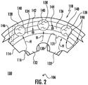
FIG. 2 is partial cross-sectional view of the stator ofFIG. 1 , showing coolant channels defined by the coolant jacket; -
FIGS. 3A-3D are partial cross-sectional views of the stator ofFIG. 1 according to embodiments, showing coolant channels having heat transfer structures, thin intermediate layers separating the coolant channel from the core, and coolant channels bounded by the core, respectively; -
FIGS. 4-6 are perspective views of implementations of the heat transfer structures ofFIGS. 3A and 3B , showing turbulators, riblets, and spires defined using additive manufacturing techniques and subtractive techniques, respectively; -
FIG. 7 is a perspective view of the stator ofFIG. 1 , showing a stator with a coolant channel defined within coolant jacket that extends helically about the core of the stator; -
FIGS. 8 and 9 are perspective views of the stator ofFIG. 1 , showing stators with coolant channels defined within the coolant jacket having flow areas that changes along the length of the stator, respectively; and -
FIG. 10 is block diagram of a method of making a stator for an electrical machine, showing steps of the method. - Reference will now be made to the drawings wherein like reference numerals identify similar structural features or aspects of the subject disclosure. For purposes of explanation and illustration, and not limitation, a partial view of an exemplary embodiment of a stator for an electrical machine in accordance with the disclosure is shown in
FIG. 1 and is designated generally byreference character 100. Other embodiments of stators, electrical machines, motor-type electrical machines, and methods of making stators in accordance with the present disclosure are shown inFIGS. 2-10 , as will eb described. The systems and methods described herein can be used for liquid-cooled electrical machines, such as motor-type electrical machines in aircraft electrical systems, though the present disclosure not limited motor-type electrical machines or to aircraft electrical systems in general. - In addition to the
stator 100, arotor 104 is illustrated inFIG. 1 . When combined, thestator 100 and therotor 104 form portions of anelectrical machine 102, such as a motor-type electrical machine. Therotor 104 is supported for rotation about arotation axis 106 and includes a plurality ofsheets 108 and one or moremagnetic elements 110. The plurality ofsheets 108 are axially stacked along therotation axis 106 and are formed from amagnetic steel material 112. The one or moremagnetic elements 110 may be fixed to therotor 104 such that they rotate with therotor 104 about therotation axis 106. It is contemplated that the one or moremagnetic elements 110 can be a permanent magnet and/or a coil, as suitable for an intended application. - The
stator 100 includes acore 114, a winding 116 (shown inFIG. 2 ), and acoolant jacket 118. The winding 116 is supported withincore 114 at a radially inner location. Thecore 114 extends circumferentially about therotation axis 106 and has afirst end portion 120, asecond end portion 122, and anintermediate portion 124. Thesecond end portion 122 is arranged on an end of thecore 114 axially opposite thefirst end portion 120. Theintermediate portion 124 of the core 114 couples thefirst end portion 120 of the core 114 to thesecond end portion 122 of thecore 114. It is contemplated that thecore 114 include a plurality ofsheets 126 laminated to one another and axially stacked along therotation axis 106. It is contemplated that thecore 114 be formed by asteel material 128, such as electric steel by way of non-limiting example. Although described herein as having a laminated core construction, it is also contemplated that cores with other structures can also benefit from the present disclosure, such as forged and sintered powder metal cores by way of non-limiting example. - The
coolant jacket 118 is deposited on anouter surface 130 of thecore 114. More specifically, thecoolant jacket 118 has a first layer 134 (shown inFIG. 2 ) and one or more second layer 136 (shown inFIG. 2 ) conformally disposed on theouter surface 130 of thecore 114, thecoolant jacket 118 inhabiting the one ormore surface discontinuity 131 defined within theouter surface 130 of thecore 114. As used herein the term "inhabit" refers to volumetrically occupy space defined by the surface discontinuity, and in proximity thereof, that would be occupied at least in part by air were a coolant jacket attached to thecore 114 using a shrink-fit process. - With reference to
FIG. 2 , a portion of thestator 100 is shown. Thecore 114 is radially bounded by theouter surface 130 and two ormore stator teeth 132. The two ormore stator teeth 132 are arranged radially inward of theouter surface 130. Coils of the winding 116 are wrapped about therespective stator teeth 132 and are connected electrically with one another in series (or parallel) to communicate magnetic flux to the rotor 104 (shown inFIG. 1 ). As will be appreciated by those of skill in the art in view of the present disclosure, application of electric current to the winding 116 generates heat H - both from resistive heating of the conductors forming the winding 116 and from magnetic flux generated by the current flow or magnetic elements carried by the rotor (e.g., permanent magnets and/or windings) - which is rejected to the environment external to thestator 100. - The
coolant jacket 118 includes a plurality of layers, e.g., thefirst layer 134 and the one or moresecond layer 136, and is arranged to communicate the heat H to the external environment. In this respect thecoolant jacket 118 defines at least partially a plurality ofcoolant channels 138 within thecoolant jacket 118. Aliquid coolant 140 may be provided to thecoolant channels 138 to receive the heat H. Theliquid coolant 140 traverses thecoolant channels 138, receives the heat H from thecore 114, and carries the heat H therewith for communication to the external environment. Examples of suitable liquid coolants include water, water-glycol, refrigerants, liquid metal, oil, brine, glycol-containing mixtures, and kerosene-based fuels. - The
first layer 134 includes a fusedmetallic particulate 142 distributed radially outward of thecore 114. The one or moresecond layer 136 includes an fusedmetallic particulate 144, also distributed radially outward of thecore 114, and is additionally fused with the underlyingfirst layer 134 to form a monolithic andunitary stator 100. It is contemplated that either (or both) the fusedmetallic particulate 142 and the fusedmetallic particulate 144 include ametallic material 146, for aluminum or titanium and/or alloys thereof. In certain embodimentsmetallic material 146 is selected to additionally limit, e.g., through the use of aluminum or an aluminum alloy, the weight of thecoolant jacket 118 while providing good thermal communication through thecoolant jacket 118. - The
first layer 134 and the one or moresecond layers 136 are conformally disposed to theouter surface 130 of thecore 114. More specifically, thefirst layer 134 and the one or moresecond layer 136 are deposited to thecore 114 and bound, at least partially, thecoolant channels 138. As shown inFIG. 2 thefirst layer 134 is deposited on theouter surface 130 of thecore 114 and circumferentially about thecore 114, and the one or moresecond layer 136 is deposited on thefirst layer 134 and circumferentially about theouter surface 130 of the core 114 at a location radially outward of thefirst layer 134. Although shown an described in a specific orientation, e.g., circumferentially about one another and thecore 114, other orientations of thefirst layer 134 and one thesecond layer 136 are possible within the scope of the present disclosure. - It is contemplated that the
first layer 134 and one or moresecond layers 136 be deposited using an additive manufacturing technique. Examples of suitable additive manufacturing techniques include cold spray techniques, wire addition techniques, and powder bed fusion techniques by way of non-limiting examples. Deposition of thefirst layer 134 and the one or moresecond layer 136 reduces the thermal resistance at an interface 148 defined between thecoolant jacket 118 and thecore 114 relative to shrink-fit cores having coolant channel formed using a subtractive process of similar geometry. - In certain embodiments the thermal resistance presented by the interface 148 can be on the order of about 70% less than that presented by a coolant jacket applied by a shrink fit process, which is unexpectedly better than expected. Without wishing to be bound by a particular theory, applicants believe that this unexpected improvement in thermal resistance is attributable to the tendency of deposited materials to displace gas resident in micro-features, e.g., the
surface discontinuity 131, defined on theouter surface 130 of the core 114 resultant from the manufacturing process, e.g., the stamping process used to from the plurality ofsheets 126, rather than impound the gases between a coolant jacket and thecore 114 as can occur when a discrete coolant jacket structure is assembled to thecore 114 using a shrink-fit technique. - With continuing reference to
FIG. 1 , it is contemplated that thefirst layer 134 and the one or moresecond layer 136 define aninlet manifold 135 and or anoutlet manifold 137. Theinlet manifold 135 and/or theoutlet manifold 137 in turn fluidly connect thecoolant channels 138 to a singular coolant inlet and/or coolant outlet. Forming theinlet manifold 135 and/or theoutlet manifold 137 can simplify the assembly of thestator 100 as there is no need to attach a coolant manifold as discrete structure. Forming theinlet manifold 135 and/or theoutlet manifold 137 can also improve the reliability of electrical machines employing thestator 100, e.g., the electrical machine 100 (shown inFIG. 1 ), as fewer coolant conduit connections need to be made during assembly - each of which can present a risk of coolant leakage. - With reference to
FIGS. 3A-3D , embodiments of thestator 100 are shown. As shown inFIG. 3A , in certain embodiments thecoolant jacket 118 can define acoolant channel 150 having aheat transfer feature 156. In this respect thecoolant channel 150 is similar to the coolant channel 138 (shown inFIG. 2 ) and additionally includes theheat transfer structure 156. Theheat transfer structure 156 is defined within thecoolant channel 150 and is formed using an additive manufacturing technique, e.g., the additive manufacturing technique used to form thefirst layer 134 and/or thesecond layer 136. During service theheat transfer surface 158 increases the surface area otherwise presented by thecoolant jacket 118 to theliquid coolant 140 traversing thecoolant channel 150. The increased surface area provided by theheat transfer feature 156 increases the rate of heat transfer between thecoolant jacket 118 and theliquid coolant 140, increasing the rate of heat rejection from thecore 114 to the liquid coolant 140 - allowing for increased rating of theelectrical machine 100. - As shown in
FIG. 3B , it is contemplated that thecoolant jacket 118 and thecore 114 can collectively define acoolant channel 152. Thecoolant channel 152 is similar to the coolant channel 138 (shown inFIG. 2 ) and additionally includes aheat transfer structure 158. Theheat transfer structure 158 is defined radially on (and within) theouter surface 130 of thecore 114. It is contemplated that theheat transfer feature 158 be defined using a subtractive manufacturing technique, such as a milling or stamping technique, increasing the surface area presented by thecore 114 to theliquid coolant 140 traversing thecoolant channel 152. The increased surface area provided by theheat transfer feature 158 increases the rate of heat transfer between the core 114 and theliquid coolant 140, increasing the rate of heat rejection from thecore 114 to theliquid coolant 140 traversing thecoolant channel 138 during operation of theelectrical machine 100. - As shown in
FIG. 3C , it is also contemplated that, in accordance with in certain embodiments, thecoolant jacket 118 can define acoolant channel 153 with a thin coolant jacket layer separating thecoolant channel 153 from thecore 114. In this respect thecoolant channel 153 is similar to the coolant channel 138 (shown inFIG. 2 ) and additionally includes a thinfirst layer 134. The thinfirst layer 134 has aradial thickness 135 that is smaller than aradial thickness 137 of the one or moresecond layers 136. The thinfirst layer 134 allows thecoolant jacket 118 to be relatively lightweight relative to a coolant jacket fit assembles to thecore 114 using a shrink-fit technique and still provide a fluid-tight seal between thecoolant channel 153 and thecore 114. This prevents infiltration of theliquid coolant 140 into thecore 114 via leak paths that may be present between the laminations, e.g., the laminations 126 (shown inFIG. 1 ), forming thecore 114. - As shown in
FIG. 3D , in further embodiments thecoolant jacket 118 can define one ormore coolant channel 154 bounded by theouter surface 130 of thecore 114. In this respect thecoolant channel 154 is similar to the coolant channel 138 (shown inFIG. 2 ) and is additionally bounded by a portion of theouter surface 130 of thecore 114. Bounding a portion of theouter surface 130 of thecore 114, theliquid coolant 140 flowing through thecoolant channel 154 flows directly across theouter surface 130 of thecore 114. This eliminates entirely the thermal resistance associated with the interface that would otherwise be present between a coolant jacket assembled to thecore 114 using a shrink fit technique and thecore 114, increasing the rate of heat transfer from thecore 114 into theliquid coolant 140 within thecoolant channel 154. It can also limits the radial thickness of thecoolant jacket 118, limiting weight of thestator 100. - With reference to
FIGS. 4-6 , theheat transfer structures 156 and theheat transfer structure 158 are shown. As shown inFIG. 4 , theheat transfer structure 156 and/or theheat transfer structure 158 can include one ormore turbulator 160. The one or more turbulator 160 is arranged transversely with respect to flow of theliquid coolant 140 through the coolant channel 150 (shown innFIG. 3A ) and/or the coolant channel 152 (shown inFIG. 3B ). In certain embodiments the one or more turbulator 160 can be an artifact, e.g., unintentional consequence of tool wear, from the stamping process used to for the sheets 126 (shown inFIG. 1 ) forming the core 114 (shown inFIG. 1 ). In accordance with certain embodiments the one or more turbulator 160 can formed using the additive manufacturing technique used to conformally dispose the first layer 134 (shown inFIG. 2 ) and/or the one or more second layer 136 (shown inFIG. 2 ) on theouter surface 130 of thecore 114. As will be appreciated by those of skill in the art in view of the present disclosure, the transverse orientation of the one or more turbulator 160 relative to the direction of the flow of theliquid coolant 140 through thecoolant channel 152 and/or thecoolant channel 154 introduces turbulence within the flow of theliquid coolant 140, promoting fluid mixing and increasing the rate of heat transfer between the stator 100 (shown inFIG. 1 ) and theliquid coolant 140. - As shown in
FIG. 5 , theheat transfer structure 156 and/or theheat transfer structure 158 can include one or more riblet orfin 162. The one or more riblet offin 162 is arranged along the direction of flow of theliquid coolant 140, increasing the surface area of the coolant jacket 118 (shown inFIG. 1 ) or the core 114 (shown inFIG. 1 ) that theliquid coolant 140 contacts while traversing the stator 100 (shown inFIG. 1 ). This increases the rate of heat transfer between thecoolant jacket 118 or thecore 114 and theliquid coolant 140. It is contemplated that the one or more riblet orfin 162 can be axially discontinuous and circumferentially displaced within the coolant channel relative to another riblet orfin 162. - As shown in
FIG. 6 , theheat transfer structure 156 and/or theheat transfer structure 158 can include one ormore spire 164. The one ormore spire 164 protrude radially into theliquid coolant 140, increasing the surface area of the coolant jacket 118 (shown inFIG. 1 ) or the core 114 (shown inFIG. 1 ) that theliquid coolant 140 contacts while traversing the stator 100 (shown inFIG. 1 ), the one ormore spire 164 increasing increase the rate of heat transfer between thecoolant jacket 118 or thecore 114 and theliquid coolant 140. - With reference to
FIG. 7 , a stator 200 is shown. The stator 200 is similar to the stator 100 (shown inFIG. 1 ) and additionally includes acoolant jacket 218. Thecoolant jacket 218 defines at least partially acoolant channel 238. Thecoolant channel 238 extends helically about therotation axis 206. More specifically, thecoolant jacket 218 defines a plurality of coolant channels 244 extending helically about therotation axis 206 spanning at least anintermediate portion 224 of thecore 214. The helical path increases the length of the coolant channel 244 with respect to the axial length ofcore 214, increasing the amount of heat communicated to the liquid coolant 140 (shown inFIG. 2 ) as the liquid coolant traverses thecoolant channel 238. As shown inFIG. 7 the helical path of thecoolant channel 238 span thefirst end portion 220, theintermediate portion 224, and thesecond end portion 222 of thecore 214. - With reference to
FIG. 8 , a stator 300 is shown. The stator 300 is similar to thestator 100 and additionally has acoolant jacket 318. Thecoolant jacket 318 defines at least partially a coolant channel 338. The coolant channel 338 has afirst flow area 366 and asecond flow area 368. Thefirst flow area 366 is greater than thesecond flow area 368. It is contemplated that the first flow area be defined by the coolant channel 344 at an axial location radially adjacent to an end turn 370 of a winding 316, e.g., radially adjacent to thefirst end portion 320 and/or thesecond end portion 322, and that the second flow area 362 be defined along theintermediate portion 324 of thecore 314. Defining thefirst flow area 366 radially adjacent to the end turn 370 increases residency time of the liquid coolant 140 (shown inFIG. 2 ) at locations radially adjacent to the end turn 370, increasing the amount of heat removed from the end turn 370. As the end turn 370 of a winding can run hotter than the portion of the winding spanning theintermediate portion 324 of thecore 314, the greater size of thefirst area 366 reduces the total range of temperature along thecore 314 during operation electrical machines employing the stator 300. - With reference to
FIG. 9 , astator 400 is shown. Thestator 400 is similar to the stator 100 (shown inFIG. 1 ) and additionally includes acoolant jacket 418. Thecoolant jacket 418 defines at least partially a coolant channel 444 having afirst flow area 466 and asecond flow area 468, thefirst flow area 466 having a greater area than thesecond flow area 468. Between thefirst flow area 466 and thesecond flow area 468 thecoolant channel 438 tapers in flow area size. For example, between thefirst flow area 466 defined on thefirst end portion 420 of the core 414 the coolant channel 444 tapers to thesecond flow area 468 at a location along theintermediate portion 424 of the coolant channel 444. Tapering thecoolant channel 438 graduates the resistance presented to the liquid coolant 140 (shown inFIG. 2 ) traversing thecoolant channel 438, promoting laminar flow within thecoolant channel 438 and limiting pressure loss in theliquid coolant 140 during traverse of thestator 400. - With reference to
FIG. 10 , amethod 500 of making a stator, e.g., the stator 100 (shown inFIG. 1 ), is shown. Themethod 500 includes conformally depositing a coolant jacket, e.g., the coolant jacket 118 (shown inFIG. 1 ), on the outer surface of a core, e.g., the outer surface 130 (shown inFIG. 2 ) of the core 114 (shown inFIG. 1 ), as shown with box 510. The coolant jacket is deposited conformally on the core by depositing a first layer using an additive manufacturing technique, e.g., the first layer 134 (shown inFIG. 2 ), on the outer surface of the core, as shown withbox 512, and depositing one or more second layer, e.g., the second layer 136 (shown inFIG. 2 ), on the outer surface of the core, as shown withbox 514. The second layer can be deposited on the outer surface of the core, the first layer, or both the outer surface of the core and the first layer, as shown withbox 520. It is contemplated that the coolant jacket be deposited using an additive manufacturing technique, such a cold-spray additive technique, wire addition additive technique, or a laser deposition technique. - As shown with
box 530, themethod 500 includes defining a coolant channel within the coolant jacket during the depositing of the first layer and the one or more second layer using the additive manufacturing technique. In certain also embodiments a heat transfer structure, e.g., the heat transfer structure 156 (shown inFIG. 6 ), is defined within the coolant channel, as shown withbox 540. As shown withbox 542, the heat transfer structure can be defined using an additive manufacturing technique, e.g., the additive manufacturing technique used deposit the coolant jacket. As shown withbox 544, the heat transfer structure can be defined using a subtractive manufacturing technique, such as with a stamping or milling operation by way of illustration and non-limiting example. It is contemplated that defining the heat transfer structure can include defining one or more of a turbulator, e.g., the one or more turbulator 160 (shown inFIG. 5 ), a riblet, e.g., the one or more riblet 162 (shown inFIG. 6 ), or the one or more spire 164 (shown inFIG. 7 ), as shown with box 550. - Electrical machines typically generate heat during operation due resistive heating of electrical conductors and magnetic flux communication. The heat is generally communicated to the external environment by conduction through the frame of the electrical machine frame to a fluid, and therethrough to the ambient environment. Since the rate of heat rejection through the frame can influence the rating of the electrical machine for a given level of current flow and/or magnetic flux, structures like fins, coolant tubes, or coolant jackets can be thermally coupled to the frame to route coolant fluid across the electrical device. Fins increase the area of the frame for heat rejection to the ambient environment while coolant tubes and coolant jackets sink heat from the electrical machine across an interface between the frame and coolant jacket.
- In embodiments described herein electrical machines employ stators having a core and coolant jacket. The coolant jacket is conformally deposited over the outer surface of the core and at least partially defines therein a coolant channel. The coolant jacket includes two or more layers deposited on the core and/or one another, limiting the thickness of the coolant jacket by limiting (or eliminating entirely) the hoop stress associated with shrink-fitting the coolant jacket to the core. In certain embodiments the first layer and the one or more second are deposited such that the thermal resistance of the interface between the core and the coolant jacket is smaller than that of a shrink-fit coolant jacket - the interface having as much as 70% less thermal resistance than a shrink-fit coolant jacket in contemplated embodiments. In accordance with certain embodiment the coolant channel can be defined with non-linear share, such as a helical shape by way of illustration and not limitation. It is also contemplated that the coolant channel can widen and narrow according to coolant flow characteristics for the heat loading at given location on the core, the coolant channel widening at locations radially adjacent to the winding end turns for example.
- The terminology used herein is for the purpose of describing particular embodiments only and is not intended to be limiting of the present disclosure. As used herein, the singular forms "a", "an" and "the" are intended to include the plural forms as well, unless the context clearly indicates otherwise. It will be further understood that the terms "comprises" and/or "comprising," when used in this specification, specify the presence of stated features, integers, steps, operations, elements, and/or components, but do not preclude the presence or addition of one or more other features, integers, steps, operations, element components, and/or groups thereof.
- While the present disclosure has been described with reference to an exemplary embodiment or embodiments, it will be understood by those skilled in the art that various changes may be made and equivalents may be substituted for elements thereof without departing from the scope of the present disclosure. In addition, many modifications may be made to adapt a particular situation or material to the teachings of the present disclosure without departing from the essential scope thereof. Therefore, it is intended that the present disclosure not be limited to the particular embodiment disclosed as the best mode contemplated for carrying out this present disclosure, but that the present disclosure will include all embodiments falling within the scope of the claims.
Claims (15)
- A stator (100), comprising:a core (114) with an outer surface extending about a rotation axis (106), wherein the outer surface defines one or more surface discontinuity therein; anda coolant jacket (118) deposited on the outer surface of the core and defining a coolant channel, wherein the coolant jacket comprises a plurality of layers conformally disposed on the outer surface of the core and inhabiting the one or more surface discontinuity.
- The stator as recited in claim 1, wherein a first layer of the plurality of layers comprises a fused metallic particulate, wherein a second layer of the plurality of layers comprises a fused metallic particulate, wherein the second layer is fused to the first layer.
- The stator as recited in claim 1, wherein the plurality of layers bound the coolant channel, or wherein at least one of the plurality of layers is arranged radially between the coolant channel and the outer surface of the core.
- The stator as recited in any preceding claim, wherein the outer surface of the core bounds the coolant channel.
- The stator as recited in any preceding claim, wherein the coolant channel extends helically about the rotation axis.
- The stator as recited in any preceding claim, wherein the coolant channel has a first flow area and a second flow area, the first flow area being larger in size than the second flow area.
- The stator as recited in claim 6, wherein the core has a first end portion, an axially opposite second end portion, and an intermediate portion coupling the first end portion to the second end portion, wherein the first flow area is defined along in the intermediate portion of the core, and wherein the second flow area is defined along the first end portion or the second end portion of the core, or
wherein the coolant channel tapers in flow area size between the first flow area and the second flow area along a length of the coolant channel. - The stator as recited in any preceding claim, further comprising a heat transfer structure arranged within the coolant channel, and optionally wherein the heat transfer structure is selected from a group including a turbulator, a riblet, and a spire.
- The stator as recited in claim 8, wherein the heat transfer structure is defined by the outer surface of the core, or wherein the heat transfer structure is defined by at least one of the plurality of layers of the coolant channel, or
wherein the heat transfer structure is formed from a fused particulate and is spaced apart from the coolant jacket by a portion of the outer surface of the core. - The stator as recited in any preceding claim, wherein the first layer has a radial thickness that is smaller than a radial thickness of the second layer.
- The stator as recited in any preceding claim, further comprising:a liquid coolant disposed within the coolant channel;a winding extending about the rotation axis and arranged radially inward of the outer surface of the core; anda rotor arranged radially inward of the core and supported for rotation about the rotation axis.
- An electrical machine, comprising:a stator as recited in any preceding claim, wherein a first layer of the plurality of layers comprises a fused metallic particulate, wherein a second layer of the plurality of layers comprises a fused metallic particulate, wherein the second layer is fused to the first layer;wherein the core comprises a steel material, wherein the coolant jacket comprises a metallic material; anda rotor arranged radially inward of the core and supported for rotation about the rotation axis.
- A motor-type electrical machine having a stator as recited in any of claims 1 to 11.
- A method of making a stator, comprising:at a core (114) having an outer surface extending about a rotation axis (106), wherein the outer surface defines one or more surface discontinuity therein,conformally depositing a coolant jacket (118) on the outer surface of the core, the depositing comprising:depositing a first layer (134) on the outer surface of the core using an additive manufacturing technique;depositing a second layer (136) over at least one of the outer surface of the core and the first layer using the additive manufacturing technique; anddefining a coolant channel within the coolant jacket during the depositing of the first layer and the second layer using the additive manufacturing technique, at least one of the first layer and the second layer inhabiting the one or more surface discontinuity.
- The method as recited in claim 14, further comprising defining a heat transfer structure arranged within the coolant channel, wherein the heat transfer structure is defined within the outer surface of the core using a subtractive technique, or wherein the heat transfer structure is defined by at least one of the plurality of layers of the coolant jacket, or wherein the heat transfer structure is formed from a fused particulate and is spaced apart from the coolant jacket by a portion of the outer surface of the core.
Applications Claiming Priority (1)
| Application Number | Priority Date | Filing Date | Title |
|---|---|---|---|
| US16/408,051 US11025108B2 (en) | 2019-05-09 | 2019-05-09 | Electrical machines with liquid cooling |
Publications (2)
| Publication Number | Publication Date |
|---|---|
| EP3736948A1 true EP3736948A1 (en) | 2020-11-11 |
| EP3736948B1 EP3736948B1 (en) | 2025-03-26 |
Family
ID=68731875
Family Applications (1)
| Application Number | Title | Priority Date | Filing Date |
|---|---|---|---|
| EP19212181.2A Active EP3736948B1 (en) | 2019-05-09 | 2019-11-28 | Electrical machines with liquid cooling |
Country Status (2)
| Country | Link |
|---|---|
| US (1) | US11025108B2 (en) |
| EP (1) | EP3736948B1 (en) |
Families Citing this family (7)
| Publication number | Priority date | Publication date | Assignee | Title |
|---|---|---|---|---|
| US12508556B2 (en) * | 2019-11-29 | 2025-12-30 | Dow Silicones Corporation | Static mixer |
| US11563354B2 (en) * | 2020-03-05 | 2023-01-24 | Dana Belgium N.V. | Electric motor cooling system and method for operation of said system |
| WO2022098636A1 (en) | 2020-11-03 | 2022-05-12 | H3X Technologies Inc. | Electric motor with integrated inverter and shared cooling system |
| KR102532529B1 (en) * | 2021-03-02 | 2023-05-15 | 경북대학교 산학협력단 | Motor and Motor Cooling System |
| US11817761B2 (en) | 2021-11-05 | 2023-11-14 | Hamilton Sundstrand Corporation | Aircraft electric motor |
| US11990825B2 (en) | 2021-11-09 | 2024-05-21 | Hamilton Sundstrand Corporation | Aircraft electric motor |
| EP4519961A4 (en) * | 2022-05-03 | 2026-04-29 | Toyon Res Corporation | TORQUE-TIGHT ELECTRIC MOTOR |
Citations (3)
| Publication number | Priority date | Publication date | Assignee | Title |
|---|---|---|---|---|
| WO2016113565A1 (en) * | 2015-01-15 | 2016-07-21 | Electronica Products Limited | Rotary electric machine |
| EP3076526A1 (en) * | 2015-04-02 | 2016-10-05 | Hamilton Sundstrand Corporation | Stator heat transfer feature |
| US20170271954A1 (en) * | 2016-03-17 | 2017-09-21 | Ford Global Technologies, Llc | Over Mold with Integrated Insert to Enhance Heat Transfer from an Electric Machine End Winding |
Family Cites Families (16)
| Publication number | Priority date | Publication date | Assignee | Title |
|---|---|---|---|---|
| US5939808A (en) | 1998-06-03 | 1999-08-17 | Adames; Fermin | Electric motor housing with integrated heat removal facilities |
| US7626292B2 (en) * | 2007-07-03 | 2009-12-01 | Caterpillar Inc. | Cast groove electric motor/generator cooling mechanism |
| US8183723B2 (en) * | 2007-07-03 | 2012-05-22 | Caterpillar Inc. | Cooling jacket and stator assembly for rotary electric device |
| DE102009038691A1 (en) | 2009-08-24 | 2011-03-03 | Siemens Aktiengesellschaft | Electric machine |
| US8816546B2 (en) * | 2010-09-23 | 2014-08-26 | Northern Power Systems, Inc. | Electromagnetic rotary machines having modular active-coil portions and modules for such machines |
| US8395287B2 (en) * | 2010-10-04 | 2013-03-12 | Remy Technologies, Llc | Coolant channels for electric machine stator |
| DE102012008209A1 (en) * | 2012-04-21 | 2013-10-24 | Volkswagen Aktiengesellschaft | Electric machine |
| US20140246933A1 (en) * | 2013-03-04 | 2014-09-04 | Remy Technologies, Llc | Liquid-cooled rotary electric machine having heat source-surrounding fluid passage |
| US20140246931A1 (en) * | 2013-03-04 | 2014-09-04 | Remy Technologies, Llc | Liquid-cooled rotary electric machine having fluid channel with auxiliary coolant groove |
| US9467023B2 (en) | 2013-07-30 | 2016-10-11 | Hamilton Sundstrand Corporation | Liquid cooled motor for cabin air compressor |
| US9299488B2 (en) | 2013-10-04 | 2016-03-29 | Hamilton Sundstrand Corporation | Magnetic devices with integral cooling channels |
| US9468131B2 (en) | 2014-04-16 | 2016-10-11 | Raytheon Company | Monolithic multi-module electronics chassis with multi-planar embedded fluid cooling channels |
| US11387725B2 (en) | 2015-05-27 | 2022-07-12 | Hamilton Sundstrand Corporation | Integrated heat dissipative structure for electric machine |
| EP3131189B1 (en) | 2015-08-12 | 2018-08-01 | Siemens Aktiengesellschaft | Rotor of an electric machine |
| US20170346370A1 (en) | 2016-05-24 | 2017-11-30 | Board Of Regents, The University Of Texas System | Maintainable liquid cooling jacket for motors |
| US10374486B2 (en) | 2017-03-24 | 2019-08-06 | Ge Aviation Systems Llc | Method and assembly of an electric machine |
-
2019
- 2019-05-09 US US16/408,051 patent/US11025108B2/en active Active
- 2019-11-28 EP EP19212181.2A patent/EP3736948B1/en active Active
Patent Citations (3)
| Publication number | Priority date | Publication date | Assignee | Title |
|---|---|---|---|---|
| WO2016113565A1 (en) * | 2015-01-15 | 2016-07-21 | Electronica Products Limited | Rotary electric machine |
| EP3076526A1 (en) * | 2015-04-02 | 2016-10-05 | Hamilton Sundstrand Corporation | Stator heat transfer feature |
| US20170271954A1 (en) * | 2016-03-17 | 2017-09-21 | Ford Global Technologies, Llc | Over Mold with Integrated Insert to Enhance Heat Transfer from an Electric Machine End Winding |
Also Published As
| Publication number | Publication date |
|---|---|
| US11025108B2 (en) | 2021-06-01 |
| US20200358325A1 (en) | 2020-11-12 |
| EP3736948B1 (en) | 2025-03-26 |
Similar Documents
| Publication | Publication Date | Title |
|---|---|---|
| EP3736948B1 (en) | Electrical machines with liquid cooling | |
| KR101863481B1 (en) | Induction motor with transverse liquid cooled rotor and stator | |
| US7208854B1 (en) | Rotor cooling system for synchronous machines with conductive sleeve | |
| CN106655563B (en) | A kind of motor cooling and the inorganic shell motor with the structure | |
| KR101947292B1 (en) | Electric machine end turn cooling apparatus | |
| US20190350111A1 (en) | Conformal heat pipe assemblies | |
| CN112636499A (en) | Oil-cooled stator, motor, electric drive axle and automobile | |
| JPH04229049A (en) | Liquid cooling of rotor for electric machine | |
| US12068640B2 (en) | Method of making a triangular rotor wedge with different layers having titanium | |
| CN105308832A (en) | Liquid-cooled stators for high-efficiency machinery | |
| US20240146134A1 (en) | Stator of an electric flux machine, and axial flux machine | |
| JP2017525162A (en) | Fluid cooled wound strip structure | |
| Rivière et al. | Design analysis of a high speed copper rotor induction motor for a traction application | |
| US11469635B2 (en) | Rotor for an electric machine | |
| US11569707B2 (en) | Apparatus and method for cooling an electrical machine | |
| JP2025515137A (en) | High torque density electric motor | |
| US20260031675A1 (en) | Electric motor with integrated heat exchanger | |
| CN104797369B (en) | Method of welding stator to cooler and stator welded to stator support | |
| EP2793375B1 (en) | A stator for an electrical machine of a mobile working machine | |
| EP2978110B1 (en) | Electrical machines with liquid cooling | |
| CN106849510B (en) | System for cooling motor stator | |
| JP2011250503A (en) | Superconducting motor | |
| JP7527427B2 (en) | STATOR ASSEMBLY FOR AN ELECTRIC MACHINE - Patent application | |
| JP2024102392A (en) | Rotating Electric Machine | |
| WO2022038827A1 (en) | Stator for rotary electric machine, rotary electric machine, and wheel |
Legal Events
| Date | Code | Title | Description |
|---|---|---|---|
| PUAI | Public reference made under article 153(3) epc to a published international application that has entered the european phase |
Free format text: ORIGINAL CODE: 0009012 |
|
| STAA | Information on the status of an ep patent application or granted ep patent |
Free format text: STATUS: THE APPLICATION HAS BEEN PUBLISHED |
|
| AK | Designated contracting states |
Kind code of ref document: A1 Designated state(s): AL AT BE BG CH CY CZ DE DK EE ES FI FR GB GR HR HU IE IS IT LI LT LU LV MC MK MT NL NO PL PT RO RS SE SI SK SM TR |
|
| AX | Request for extension of the european patent |
Extension state: BA ME |
|
| STAA | Information on the status of an ep patent application or granted ep patent |
Free format text: STATUS: REQUEST FOR EXAMINATION WAS MADE |
|
| 17P | Request for examination filed |
Effective date: 20210505 |
|
| RBV | Designated contracting states (corrected) |
Designated state(s): AL AT BE BG CH CY CZ DE DK EE ES FI FR GB GR HR HU IE IS IT LI LT LU LV MC MK MT NL NO PL PT RO RS SE SI SK SM TR |
|
| STAA | Information on the status of an ep patent application or granted ep patent |
Free format text: STATUS: EXAMINATION IS IN PROGRESS |
|
| 17Q | First examination report despatched |
Effective date: 20220519 |
|
| GRAP | Despatch of communication of intention to grant a patent |
Free format text: ORIGINAL CODE: EPIDOSNIGR1 |
|
| STAA | Information on the status of an ep patent application or granted ep patent |
Free format text: STATUS: GRANT OF PATENT IS INTENDED |
|
| INTG | Intention to grant announced |
Effective date: 20241017 |
|
| GRAS | Grant fee paid |
Free format text: ORIGINAL CODE: EPIDOSNIGR3 |
|
| GRAA | (expected) grant |
Free format text: ORIGINAL CODE: 0009210 |
|
| STAA | Information on the status of an ep patent application or granted ep patent |
Free format text: STATUS: THE PATENT HAS BEEN GRANTED |
|
| AK | Designated contracting states |
Kind code of ref document: B1 Designated state(s): AL AT BE BG CH CY CZ DE DK EE ES FI FR GB GR HR HU IE IS IT LI LT LU LV MC MK MT NL NO PL PT RO RS SE SI SK SM TR |
|
| REG | Reference to a national code |
Ref country code: GB Ref legal event code: FG4D |
|
| REG | Reference to a national code |
Ref country code: CH Ref legal event code: EP |
|
| REG | Reference to a national code |
Ref country code: DE Ref legal event code: R096 Ref document number: 602019067708 Country of ref document: DE |
|
| REG | Reference to a national code |
Ref country code: IE Ref legal event code: FG4D |
|
| PG25 | Lapsed in a contracting state [announced via postgrant information from national office to epo] |
Ref country code: RS Free format text: LAPSE BECAUSE OF FAILURE TO SUBMIT A TRANSLATION OF THE DESCRIPTION OR TO PAY THE FEE WITHIN THE PRESCRIBED TIME-LIMIT Effective date: 20250626 |
|
| PG25 | Lapsed in a contracting state [announced via postgrant information from national office to epo] |
Ref country code: FI Free format text: LAPSE BECAUSE OF FAILURE TO SUBMIT A TRANSLATION OF THE DESCRIPTION OR TO PAY THE FEE WITHIN THE PRESCRIBED TIME-LIMIT Effective date: 20250326 |
|
| REG | Reference to a national code |
Ref country code: LT Ref legal event code: MG9D |
|
| PG25 | Lapsed in a contracting state [announced via postgrant information from national office to epo] |
Ref country code: NO Free format text: LAPSE BECAUSE OF FAILURE TO SUBMIT A TRANSLATION OF THE DESCRIPTION OR TO PAY THE FEE WITHIN THE PRESCRIBED TIME-LIMIT Effective date: 20250626 |
|
| PG25 | Lapsed in a contracting state [announced via postgrant information from national office to epo] |
Ref country code: HR Free format text: LAPSE BECAUSE OF FAILURE TO SUBMIT A TRANSLATION OF THE DESCRIPTION OR TO PAY THE FEE WITHIN THE PRESCRIBED TIME-LIMIT Effective date: 20250326 |
|
| PG25 | Lapsed in a contracting state [announced via postgrant information from national office to epo] |
Ref country code: LV Free format text: LAPSE BECAUSE OF FAILURE TO SUBMIT A TRANSLATION OF THE DESCRIPTION OR TO PAY THE FEE WITHIN THE PRESCRIBED TIME-LIMIT Effective date: 20250326 |
|
| PG25 | Lapsed in a contracting state [announced via postgrant information from national office to epo] |
Ref country code: GR Free format text: LAPSE BECAUSE OF FAILURE TO SUBMIT A TRANSLATION OF THE DESCRIPTION OR TO PAY THE FEE WITHIN THE PRESCRIBED TIME-LIMIT Effective date: 20250627 Ref country code: BG Free format text: LAPSE BECAUSE OF FAILURE TO SUBMIT A TRANSLATION OF THE DESCRIPTION OR TO PAY THE FEE WITHIN THE PRESCRIBED TIME-LIMIT Effective date: 20250326 |
|
| REG | Reference to a national code |
Ref country code: NL Ref legal event code: MP Effective date: 20250326 |
|
| PG25 | Lapsed in a contracting state [announced via postgrant information from national office to epo] |
Ref country code: NL Free format text: LAPSE BECAUSE OF FAILURE TO SUBMIT A TRANSLATION OF THE DESCRIPTION OR TO PAY THE FEE WITHIN THE PRESCRIBED TIME-LIMIT Effective date: 20250326 |
|
| PG25 | Lapsed in a contracting state [announced via postgrant information from national office to epo] |
Ref country code: SE Free format text: LAPSE BECAUSE OF FAILURE TO SUBMIT A TRANSLATION OF THE DESCRIPTION OR TO PAY THE FEE WITHIN THE PRESCRIBED TIME-LIMIT Effective date: 20250326 |
|
| REG | Reference to a national code |
Ref country code: AT Ref legal event code: MK05 Ref document number: 1779955 Country of ref document: AT Kind code of ref document: T Effective date: 20250326 |
|
| PG25 | Lapsed in a contracting state [announced via postgrant information from national office to epo] |
Ref country code: SM Free format text: LAPSE BECAUSE OF FAILURE TO SUBMIT A TRANSLATION OF THE DESCRIPTION OR TO PAY THE FEE WITHIN THE PRESCRIBED TIME-LIMIT Effective date: 20250326 |
|
| PG25 | Lapsed in a contracting state [announced via postgrant information from national office to epo] |
Ref country code: ES Free format text: LAPSE BECAUSE OF FAILURE TO SUBMIT A TRANSLATION OF THE DESCRIPTION OR TO PAY THE FEE WITHIN THE PRESCRIBED TIME-LIMIT Effective date: 20250326 Ref country code: PT Free format text: LAPSE BECAUSE OF FAILURE TO SUBMIT A TRANSLATION OF THE DESCRIPTION OR TO PAY THE FEE WITHIN THE PRESCRIBED TIME-LIMIT Effective date: 20250728 |
|
| PG25 | Lapsed in a contracting state [announced via postgrant information from national office to epo] |
Ref country code: PL Free format text: LAPSE BECAUSE OF FAILURE TO SUBMIT A TRANSLATION OF THE DESCRIPTION OR TO PAY THE FEE WITHIN THE PRESCRIBED TIME-LIMIT Effective date: 20250326 Ref country code: IT Free format text: LAPSE BECAUSE OF FAILURE TO SUBMIT A TRANSLATION OF THE DESCRIPTION OR TO PAY THE FEE WITHIN THE PRESCRIBED TIME-LIMIT Effective date: 20250326 |
|
| PG25 | Lapsed in a contracting state [announced via postgrant information from national office to epo] |
Ref country code: AT Free format text: LAPSE BECAUSE OF FAILURE TO SUBMIT A TRANSLATION OF THE DESCRIPTION OR TO PAY THE FEE WITHIN THE PRESCRIBED TIME-LIMIT Effective date: 20250326 |
|
| PG25 | Lapsed in a contracting state [announced via postgrant information from national office to epo] |
Ref country code: EE Free format text: LAPSE BECAUSE OF FAILURE TO SUBMIT A TRANSLATION OF THE DESCRIPTION OR TO PAY THE FEE WITHIN THE PRESCRIBED TIME-LIMIT Effective date: 20250326 |
|
| PG25 | Lapsed in a contracting state [announced via postgrant information from national office to epo] |
Ref country code: RO Free format text: LAPSE BECAUSE OF FAILURE TO SUBMIT A TRANSLATION OF THE DESCRIPTION OR TO PAY THE FEE WITHIN THE PRESCRIBED TIME-LIMIT Effective date: 20250326 |
|
| PG25 | Lapsed in a contracting state [announced via postgrant information from national office to epo] |
Ref country code: SK Free format text: LAPSE BECAUSE OF FAILURE TO SUBMIT A TRANSLATION OF THE DESCRIPTION OR TO PAY THE FEE WITHIN THE PRESCRIBED TIME-LIMIT Effective date: 20250326 |
|
| PG25 | Lapsed in a contracting state [announced via postgrant information from national office to epo] |
Ref country code: IS Free format text: LAPSE BECAUSE OF FAILURE TO SUBMIT A TRANSLATION OF THE DESCRIPTION OR TO PAY THE FEE WITHIN THE PRESCRIBED TIME-LIMIT Effective date: 20250726 |
|
| REG | Reference to a national code |
Ref country code: DE Ref legal event code: R097 Ref document number: 602019067708 Country of ref document: DE |
|
| PG25 | Lapsed in a contracting state [announced via postgrant information from national office to epo] |
Ref country code: DK Free format text: LAPSE BECAUSE OF FAILURE TO SUBMIT A TRANSLATION OF THE DESCRIPTION OR TO PAY THE FEE WITHIN THE PRESCRIBED TIME-LIMIT Effective date: 20250326 |
|
| PGFP | Annual fee paid to national office [announced via postgrant information from national office to epo] |
Ref country code: FR Payment date: 20251022 Year of fee payment: 7 |
|
| PG25 | Lapsed in a contracting state [announced via postgrant information from national office to epo] |
Ref country code: CZ Free format text: LAPSE BECAUSE OF FAILURE TO SUBMIT A TRANSLATION OF THE DESCRIPTION OR TO PAY THE FEE WITHIN THE PRESCRIBED TIME-LIMIT Effective date: 20250326 |
|
| PLBE | No opposition filed within time limit |
Free format text: ORIGINAL CODE: 0009261 |
|
| STAA | Information on the status of an ep patent application or granted ep patent |
Free format text: STATUS: NO OPPOSITION FILED WITHIN TIME LIMIT |
|
| REG | Reference to a national code |
Ref country code: CH Ref legal event code: L10 Free format text: ST27 STATUS EVENT CODE: U-0-0-L10-L00 (AS PROVIDED BY THE NATIONAL OFFICE) Effective date: 20260211 |
|
| 26N | No opposition filed |
Effective date: 20260105 |