EP3736615A1 - A cabinet and a method of operating such a cabinet - Google Patents
A cabinet and a method of operating such a cabinet Download PDFInfo
- Publication number
- EP3736615A1 EP3736615A1 EP19305602.5A EP19305602A EP3736615A1 EP 3736615 A1 EP3736615 A1 EP 3736615A1 EP 19305602 A EP19305602 A EP 19305602A EP 3736615 A1 EP3736615 A1 EP 3736615A1
- Authority
- EP
- European Patent Office
- Prior art keywords
- insert
- base plate
- cabinet
- cover
- locking arm
- Prior art date
- Legal status (The legal status is an assumption and is not a legal conclusion. Google has not performed a legal analysis and makes no representation as to the accuracy of the status listed.)
- Granted
Links
Images



Classifications
-
- G—PHYSICS
- G02—OPTICS
- G02B—OPTICAL ELEMENTS, SYSTEMS OR APPARATUS
- G02B6/00—Light guides; Structural details of arrangements comprising light guides and other optical elements, e.g. couplings
- G02B6/44—Mechanical structures for providing tensile strength and external protection for fibres, e.g. optical transmission cables
- G02B6/4439—Auxiliary devices
- G02B6/444—Systems or boxes with surplus lengths
- G02B6/4453—Cassettes
- G02B6/4455—Cassettes characterised by the way of extraction or insertion of the cassette in the distribution frame, e.g. pivoting, sliding, rotating or gliding
-
- A—HUMAN NECESSITIES
- A47—FURNITURE; DOMESTIC ARTICLES OR APPLIANCES; COFFEE MILLS; SPICE MILLS; SUCTION CLEANERS IN GENERAL
- A47B—TABLES; DESKS; OFFICE FURNITURE; CABINETS; DRAWERS; GENERAL DETAILS OF FURNITURE
- A47B97/00—Furniture or accessories for furniture, not provided for in other groups of this subclass
- A47B2097/003—Cable holders; cable organisers
-
- A—HUMAN NECESSITIES
- A47—FURNITURE; DOMESTIC ARTICLES OR APPLIANCES; COFFEE MILLS; SPICE MILLS; SUCTION CLEANERS IN GENERAL
- A47B—TABLES; DESKS; OFFICE FURNITURE; CABINETS; DRAWERS; GENERAL DETAILS OF FURNITURE
- A47B46/00—Cabinets, racks or shelf units, having one or more surfaces adapted to be brought into position for use by extending or pivoting
- A47B46/005—Cabinets, racks or shelf units, having one or more surfaces adapted to be brought into position for use by extending or pivoting by displacement in a vertical plane; by rotating about a horizontal axis
-
- A—HUMAN NECESSITIES
- A47—FURNITURE; DOMESTIC ARTICLES OR APPLIANCES; COFFEE MILLS; SPICE MILLS; SUCTION CLEANERS IN GENERAL
- A47B—TABLES; DESKS; OFFICE FURNITURE; CABINETS; DRAWERS; GENERAL DETAILS OF FURNITURE
- A47B81/00—Cabinets or racks specially adapted for other particular purposes, e.g. for storing guns or skis
-
- G—PHYSICS
- G02—OPTICS
- G02B—OPTICAL ELEMENTS, SYSTEMS OR APPARATUS
- G02B6/00—Light guides; Structural details of arrangements comprising light guides and other optical elements, e.g. couplings
- G02B6/44—Mechanical structures for providing tensile strength and external protection for fibres, e.g. optical transmission cables
- G02B6/4439—Auxiliary devices
- G02B6/444—Systems or boxes with surplus lengths
- G02B6/44528—Patch-cords; Connector arrangements in the system or in the box
Definitions
- the cover 12 comprises a front plate 21, a top wall 22 and two opposite side walls 23, 24.
- the top wall 22 and the two opposite side walls 23, 24 extend substantially perpendicular from the front plate 21.
- the cover 12 is formed in sheet metal, such as steel or aluminum, and is, e.g. formed in a single integrated piece.
- the cover 12 is formed with tabs 25 to be received in the gaps 19 of the base plate 11, wherein the tabs 25 are engaging top ends of the side flanges 17, 18 when the cover 12 is connected to the base plate 11 and the cabinet 10 is in the closed position.
- the tabs 25 are arranged for holding the cover 12 to the base plate 11 and, e.g. preventing the cover 12 from unintentional displacement in a direction downwards.
- the cover 12 is formed with sealing flanges 26 in an end opposite the top wall 22, which end for example is a bottom end.
- the sealing flanges 26 are arranged in the front plate 21 and in one end of each of the side walls 23, 24.
- the sealing flanges 26 extend substantially perpendicular from the front plate 21 and the side walls 23, 24, respectively.
- the plane of the back plate 15 is arranged between the plane of the distal portion of the edge portion 28 and a plane of the front plate 21 of the cover 12.
- the holes 27 are e.g. arranged adjacent the edge portion 28.
- the distal portion of the edge portion 28 is formed with through apertures 29, such as key holes for fastening the base plate 11 to a wall or similar.
- the side flanges 17, 18 of the base plate 11 are arranged for overlapping the side walls 23, 24 of the cover 12.
- the side flanges 17, 18 of the base plate 11 are arranged for engaging the side walls 23, 24 of the cover 12.
- the insert 31 comprises an insert frame 35 and a cassette 36, wherein the cassette 36 is rotatable in relation to the insert frame 35, which is illustrated schematically by means of the arrow D in Fig. 8 .
- the insert frame 35 is connected to another type of object, such as a computer device or other electronic or non-electronic device, in a similar rotatable manner.
- the cassette 36 is a connector cassette for installation of cables or fibers.
- the cassette 36 is a splice cassette for installation of optical fibers.
- the axis of rotation of the insert 31 is arranged in a bottom part of the insert 31, wherein the axis of rotation of the cassette 36 is arranged in a top portion or in the vicinity of the top portion of the insert 31.
- the insert 31 is rotatable outwards and downwards from the base plate 11, wherein the cassette 36 is rotatable outwards and upwards from the insert frame 35.
- the cassette 36 is connected to the insert frame 35 also through another rotatable joint 38, which e.g. has an axis of rotation in parallel with the other rotatable joint 37.
- the top sealing 39 is arranged for engaging the top wall 22 of the cover 12, wherein the first side sealing 40 and the second side sealing 41 are arranged for engaging the side walls 23, 24 of the cover 12.
- the top sealing 39 is arranged along the top flange 16.
- the top flange 16 is arranged on the inner side of the top flange 16.
- the top sealing 39 is arranged on the back plate 15 adjacent the top flange 16.
- the side sealings 40, 41 are arranged on the side walls 23, 24 or on the back plate 15 along and adjacent to the side walls 23, 24.
- the sealings 39-41 are arranged to provide a sealing also in the gaps 19.
Landscapes
- Physics & Mathematics (AREA)
- General Physics & Mathematics (AREA)
- Optics & Photonics (AREA)
- Casings For Electric Apparatus (AREA)
Abstract
Description
- The present invention relates to a cabinet. More specifically, the present invention relates to a cabinet comprising a base plate, an insert and an openable cover, wherein the cabinet is operable between an open position and a closed position, and wherein the cover, at least in the closed position of the cabinet, is connected to the base plate to form an interior space for housing the insert. This type of cabinets is generally used as a connector cabinet, such as a cable cabinet or an optical fiber cabinet having an insert supporting a cassette for installation of cables, fibers or similar. One type of such cabinets is optical fiber splice cabinets having a splice cassette for installation of fibers. Alternatively, this type of cabinets can be used for a variety of different purposes, such as for installation of other electronic devices, computer components or for storing different types of objects. The present invention also relates to a method for operating such a cabinet.
- There is a plurality of different types of cabinets in the prior art. One type of prior art cabinets comprises a base plate and a removable cover together forming an interior space for an insert supporting one or more objects. Such cabinets can be made of sheet metal, wherein e.g. the cover is formed with a front plate and side walls and a locking device is arranged to lock the cover to the base plate. Such cabinets are used for different purposes and it is also known to use such cabinets for supporting one or more cassettes, such as splice cassettes for splicing fibers or other types of connecting cassettes for connecting cables or similar.
- One problem with such prior art cabinets is that it is difficult to access the interior space of the cabinet, such as the insert or objects supported by the insert. For connector cabinets of prior art this results in difficult and labour-intensive installation of cables or fibers, which increase cost and also increase the risk of work-related injuries. Hence, there is a need for a more user-friendly cabinet, such as a connector cabinet.
- An object of the present invention is to mitigate, alleviate or eliminate one or more of the above-identified deficiencies or drawbacks of cabinets according to prior art and provide an improved cabinet and method of operating such a cabinet. The present invention results in improved access to objects inside the cabinet, such as a connector cassette or similar.
- The present invention relates to a cabinet comprising a base plate, an insert and an openable cover, wherein the cabinet has an open position and a closed position, and wherein the cover, at least in the closed position of the cabinet, is connected to the base plate to form an interior space for housing the insert, characterised in that the base plate is arranged with a resiliently flexible locking arm for locking the cover to the base plate in the closed position of the cabinet, and the insert is movably connected to the base plate, wherein the insert is movable from a first position for storing inside the interior space of the cabinet to a projecting second position when the cabinet is in its open position, and wherein the locking arm is arranged to engage the insert to keep the insert in the second position. The combination of the movable insert and the locking arm for locking the cover to the base plate and also for supporting the insert in the projecting second position result in a cabinet wherein access of the insert is facilitated. Hence, the insert can be pulled or rotated to the projecting second position, such as an elevated or pulled-out position, to bring the insert or at least a portion thereof closer to a person for improved access. At the same time the invention results in a possibility to manufacture the cabinet in a simple and cost efficient manner.
- The insert can be connected to the base plate through a rotatable connection, so that the insert is rotatable from the first position to the second position. This results in a simple and reliable connection for moving the insert from the first position to the projecting second position, wherein a portion of the insert is brought to a position which is more easily accessed by a person while providing a cabinet that is simple to manufacture.
- The base plate with the locking arm can be formed in a single integrated piece of sheet metal. For example, the base plate can be arranged with holes for receiving lugs of the insert to form the rotatable connection between the base plate and the insert. Hence, the cabinet can be made of few parts, wherein the base plate can be manufactured by folding a single piece of sheet metal. Also the cover can be formed in a single integrated piece of sheet metal, e.g. by folding.
- The locking arm can be biased towards the locking position and a position for keeping the insert in the second position. The locking arm can be biased to said position by an inherent resilient flexibility of the material, such as sheet metal, of the locking arm. Hence, the locking arm is efficiently holding the cover in place when the cabinet is in the closed position and can be arranged to automatically take a position for supporting or holding the insert in the projecting second position when the cabinet is in its open position and the insert has been moved to its projecting second position.
- The base plate can be formed with opposite side flanges having a top edge for engaging a tab of the cover. Hence, this results in a simple and efficient structure for holding the cover in place against the base plate when the cabinet is in the closed position. It also provides for easy opening and closing of the cabinet. The base plate can also comprise a top flange.
- The base plate can be provided with a sealing for sealing against the cover to provide a tight cabinet and thereby prevent debris, dust, liquid, etc. from entering the cabinet.
- The cover can comprise a front plate, a top wall and two opposite side walls, wherein the locking arm is arranged to extend across the top wall and engage the front plate in the closed position of the cabinet. The front plate and the side walls of the cover can comprise sealing flanges for engaging a bottom wall of the insert. The insert and/or the sealing flanges can be provided with a sealing to provide a tight cabinet and thereby prevent debris, dust, liquid, etc. from entering the cabinet.
- The cover, such as the side walls, can be formed with hooks, e.g. in a bottom portion, for engaging the base plate. Hence, this results in a simple and efficient structure for holding the cover in place against the base plate when the cabinet is in the closed position. It can also provide for easy opening and closing of the cabinet.
- The insert can comprise an insert frame and a cassette, wherein the cassette is rotatable in relation to the insert frame. Hence, the insert frame can be moved to the projecting second position and then the cassette can be rotated out from the cassette frame, wherein improved access of the cassette is achieved. For example, the cabinet can be an electronic cabinet, such as a cable cabinet for connecting cables and fibers, wherein the cassette can be a connector cassette, such as a splice cassette.
- The present invention also relates to a method of operating a cabinet comprising a base plate, a cover and an insert, wherein the cover, at least in a closed position of the cabinet, is connected to the base plate to form an interior space for housing the insert, comprising the steps of
- a) moving a resiliently flexible locking arm of the base plate from a locked position, in which it is locking the cover to the base plate, to an unlocked position,
- b) removing the cover from the base plate,
- c) moving the insert from a first position for storing inside the interior space of the cabinet to a projecting second position, and
- d) bring the locking arm to engage the insert to keep the insert in the second position.
- Further characteristics and advantages of the present invention will become apparent from the description of embodiments below, the appended drawings and the dependent claims.
- The invention will now be described more in detail with the aid of embodiments and with reference to the appended drawings, in which
-
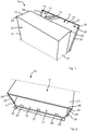
Fig. 1 is a schematic perspective view showing a part of a base plate and a cover of a cabinet according to one embodiment and illustrating the cabinet in a partially open position, -
Fig. 2 is a schematic perspective view showing a part of the cabinet according to one embodiment, -
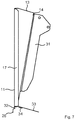
Fig. 3 is a schematic side view of a cabinet according to one embodiment showing the base plate and the cover of the cabinet, wherein the cover is connected and locked to the base plate and the cabinet is in a locked and closed position, -
Fig. 4 is a schematic side view according toFig. 3 , showing the cover unlocked from the base plate wherein the cabinet is in an unlocked position, -
Fig. 5 is a schematic side view of the cabinet ofFigs. 3 and 4 , showing opening of the cabinet, wherein the cover is partially removed from the base plate to reveal an insert of the cabinet, -
Fig. 6 is a schematic side view of a part of the cabinet ofFigs. 3-5 , wherein the cover has been removed from the base plate and the insert is in a first position for storage, -
Fig. 7 is a schematic side view of a part of the cabinet according toFig. 6 , wherein the insert is in a projecting second position for improved access, -
Fig. 8 is a schematic side view of a part of the cabinet according toFig. 7 , wherein a cassette of the insert has been turned to a position for access, and -
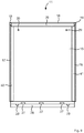
Fig. 9 is a schematic front view of the base plate according to one embodiment. - With reference to
Fig. 1 a part of acabinet 10 is illustrated according to one embodiment. Thecabinet 10 is arranged for housing one or more objects (not illustrated inFig. 1 ). In the described embodiments thecabinet 10 is a connector cabinet, such as a cable cabinet or an optical fiber cabinet. For example, thecabinet 10 is an optical fiber splice cabinet. Alternatively, thecabinet 10 is arranged for accommodating other types of objects, such as computer devices or other electronic devices. In the illustrated embodiments, thecabinet 10 is of rectangular shape. - The
cabinet 10 comprises abase plate 11 and acover 12. For example, thebase plate 11 is arranged to be fastened to a wall, such as a building wall or a wall in a bigger cabinet, e.g. in the form of a street cabinet or similar. According to one embodiment, thecabinet 10 is arranged as a street cabinet. In an alternative embodiment, which is not illustrated in the drawings, thebase plate 11 is arranged to be fastened to a stand or a rack or similar. For example, thebase plate 11 is formed in metal, such as sheet metal. For example, thebase plate 11 is formed in steel or aluminum. According to one embodiment, thebase plate 11 is formed in a single integrated piece, e.g. by folding a single integrated piece of sheet metal. The thickness of the sheet metal is, e.g. from 0.4 to 2 mm. The sheet metal material may provide shielding properties, both for optical (light) and electrical (magnetic) applications. - The
base plate 11 and thecover 12 together form an interior space for accommodating the one or more objects. Thecover 12 is openable, wherein thecabinet 10 can be set in an open position, wherein thecover 12 is at least partially removed from thebase plate 11, and a closed position, wherein thecover 12 is connected to thebase plate 11 to form the interior space. For example, thecover 12 is removable from thebase plate 11. Thebase plate 11 is arranged with a resilientlyflexible locking arm 13 for locking thecover 12 to thebase plate 11 when thecabinet 10 is in the closed position. For example, the lockingarm 13 is made of sheet metal providing the resilient elastic properties of the lockingarm 13. In the illustrated embodiment, the lockingarm 13 is formed with a lockingflange 14 for engaging thecover 12 and holding thecover 12 to thebase plate 11 in the closed position. - In the illustrated embodiment, the
base plate 11 comprises aback plate 15, atop flange 16, andopposite side flanges top flange 16 and theside flanges base plate 11 and extend substantially perpendicular to theback plate 15. The lockingarm 13, theback plate 15, thetop flange 16 and theside flanges base plate 11 is substantially rectangular. Thetop flange 16 and theside flanges base plate 11 leaving agap 19 in each top corner. Optionally, thebase plate 11 comprisesopenings 20 for mounting of thebase plate 11 to a wall or similar. - In the illustrated embodiment, the
cover 12 comprises afront plate 21, atop wall 22 and twoopposite side walls top wall 22 and the twoopposite side walls front plate 21. For example, thecover 12 is formed in sheet metal, such as steel or aluminum, and is, e.g. formed in a single integrated piece. Thecover 12 is formed withtabs 25 to be received in thegaps 19 of thebase plate 11, wherein thetabs 25 are engaging top ends of theside flanges cover 12 is connected to thebase plate 11 and thecabinet 10 is in the closed position. Hence, thetabs 25 are arranged for holding thecover 12 to thebase plate 11 and, e.g. preventing thecover 12 from unintentional displacement in a direction downwards. According to one embodiment, the top ends of theside flanges cover 12 into thegaps 19. For example, thecover 12 is arranged to be received within thetop flange 16 and theside flanges cover 12 is connected to thebase plate 11 and thecabinet 10 is in the closed position. In the closed position the lockingarm 13 is arranged to extend across thetop wall 22 and engage thefront plate 21, which is described in more detail below. - With reference also to
Fig. 2 thecover 12 is formed with sealingflanges 26 in an end opposite thetop wall 22, which end for example is a bottom end. For example, the sealingflanges 26 are arranged in thefront plate 21 and in one end of each of theside walls flanges 26 extend substantially perpendicular from thefront plate 21 and theside walls - In the illustrated embodiment, the
base plate 11 is formed with one ormore holes 27. For example, thebase plate 11 is formed with a plurality ofholes 27, which, e.g. are aligned and distributed over a width of theback plate 15. For example, thebase plate 11 is formed with at least twoholes 27, such as three ormore holes 27. In the embodiment ofFig. 2 , thebase plate 11 comprises a projectingedge portion 28, such as a bottom edge portion. For example, theedge portion 28 is substantially L-shaped and comprises a proximal portion extending perpendicular to theback plate 15 and a distal portion extending in a plane parallel to a plane of theback plate 15, wherein the proximal portion connects the distal portion to theback plate 15. In the illustrated embodiment, the plane of theback plate 15 is arranged between the plane of the distal portion of theedge portion 28 and a plane of thefront plate 21 of thecover 12. Theholes 27 are e.g. arranged adjacent theedge portion 28. In the illustrated embodiment, the distal portion of theedge portion 28 is formed with throughapertures 29, such as key holes for fastening thebase plate 11 to a wall or similar. According to one embodiment theside flanges base plate 11 are arranged for overlapping theside walls cover 12. For example, theside flanges base plate 11 are arranged for engaging theside walls cover 12. - With reference to
Figs. 3-6 opening of thecabinet 10 is illustrated schematically according to one embodiment. InFig. 3 thecabinet 10 is illustrated in a closed and locked position, wherein the lockingarm 13 engages thecover 12 for locking thereof to thebase plate 11. For example, an inner side of thetop flange 16 engages an outer side of thetop wall 22, wherein inner sides of theside flanges side walls cover 12 compriseshooks 30 for connecting thecover 12 to thebase plate 11 in a side opposite the lockingarm 13. For example, thehooks 30 are arranged in a bottom side of thecover 12. According to one embodiment, thehooks 30 are arranged in an end of the sealingflanges 26 of theside walls flanges 26 can be seen inFig. 2 . Thehooks 29 are arranged to enclose an edge of thebase plate 11, such as an edge of theback plate 15 adjacent theside flanges hooks 30 are arranged to engage a back side of thebase plate 11 to prevent a bottom part of thecover 12 to be rotated out from the base plate when thecabinet 10 is in the closed position. - The locking
arm 13 is movable from a locked position, as seen inFig. 3 , to an unlocked position, as seen inFig. 4 . The lockingarm 13 is bendable at or rotatable around its connection to the remaining portions of thebase plate 11 to move the lockingarm 13 between the locked and unlocked positions. For example, the lockingarm 13 is bendable at or rotatable around its connection to thetop flange 16 or to theback plate 15. The lockingarm 13 is bendable or rotatable and biased towards its locked position due to its inherent resilient flexible properties. To open thecabinet 10 the lockingarm 13 is disengaged from thecover 12. For example, the lockingflange 14 of the lockingarm 13 is disengaged from thefront plate 21 of thecover 12 by bending or rotating the lockingarm 13 away from thecover 12 as illustrated by means of the arrow A inFig. 4 . For example, the lockingarm 13 is configured to be operated manually by an operator. After unlocking thecabinet 10 by moving the lockingarm 13 to the unlocked position, thecover 12 is rotated away from thebase plate 11, which is illustrated by means of the arrow B inFig. 5 . For example, a top portion of thecover 12 is rotated away from thebase plate 11, wherein thetabs 25 are disengaged from thebase plate 11. When thetabs 25 are disengaged from thebase plate 11, thehooks 30 can be disengaged and thecover 12 removed from the basedplate 11. A schematic view where thecover 11 has been removed is illustrated inFig. 6 . According to the illustrated embodiment, thecover 12 is removed from thebase plate 11 to set thecabinet 10 in the open position. Alternatively, the upper part of thecover 12 is rotated away from the upper part of thebase plate 11, while thecover 12 is connected to the lower part of thebase plate 11, e.g. by means of thehooks 30 cooperating with openings in thebase plate 11. - As illustrated in
Figs. 5 and6 thecabinet 10 comprises aninsert 31. Thebase plate 11 and thecover 12 are arranged for accommodating theinsert 31. As seen inFigs. 6 and7 , theinsert 31 is connected to thebase plate 11. Theinsert 31 is movably connected to thebase plate 11, wherein theinsert 31 is movable from a first position as illustrated inFig. 6 to a second position as illustrated inFig. 7 in a direction illustrated schematically by means of the arrow C inFig. 6 . The first position is a storing position for storing inside the interior space of thecabinet 10. The second position is a projecting position for improved access for an operator, wherein at least a top portion of theinsert 31 is pulled out from thebase plate 11. For example, theinsert 31 is connected to thebase plate 11 through a rotatable connection, wherein theinsert 31 is rotatable around an axis of rotation formed by the rotatable connection. In the illustrated embodiment, theinsert 31 compriseslugs 32 arranged in theholes 27 of thebase plate 11 to form the connection between theinsert 31 and thebase plate 11, such as the rotating connection. Said holes 27 are described above with reference toFig. 2 . For example, thelugs 32 are arranged in a bottom portion of theinsert 31. Theinsert 31 may also be fastened to thebase plate 11 by means of a removable screw, such as a single captive screw, e.g. in a top portion of theinsert 31, which screw is removed to move theinsert 31 to the second position. When thecabinet 10 is in its open position, e.g. when thecover 12 has been removed from thebase plate 11, theinsert 31 is movable from the retracted first position ofFig. 6 to the projecting second position ofFig. 7 . - In the illustrated embodiment, the
insert 31 comprises abottom wall 33. For example, thebottom wall 33 is arranged to form a bottom wall of thecabinet 10 when thecabinet 10 is in its closed position. Hence, thebottom wall 33 is arranged for engaging the sealingflanges 26 of thecover 12. For example, an outer side of thebottom wall 33 and/or an inner side of the sealingflanges 26 is/are provided with a sealing to provide a tight sealing between thebottom wall 33 and the sealingflanges 26. In the illustrated embodiment, thebottom wall 33 is provided with a sealing 34 to provide a tight sealing between thebottom wall 33 and the sealingflanges 26 of the cover. In an alternative embodiment, thecover 12 is formed with a bottom wall instead of theinsert 31 or in addition to thebottom wall 33 of theinsert 31. - With reference particularly to
Fig. 7 the lockingarm 13 is arranged to engage theinsert 31 when theinsert 31 is in its projecting second position to support and maintain theinsert 31 in the projecting second position and prevent it from unintentionally returning to the retracted first position ofFig. 6 . In the illustrated embodiment, the lockingarm 13 is arranged for engaging a back side of theinsert 31 to keep it in the second position. For example, the lockingflange 14 of the lockingarm 13 is arranged for engaging the back side of theinsert 31 when theinsert 31 is in the second position. Alternatively, the lockingarm 13 or the lockingflange 14 thereof is arranged for cooperating with a recess in theinsert 31 to hold theinsert 31 in the second position. For example, the lockingarm 13 is biased towards a position in which it engages theinsert 31. For example, the lockingarm 13 is biased, through its inherent resilient flexible properties, towards a locking position when thecabinet 10 is closed and towards a position for engaging theinsert 31 when theinsert 31 has been moved to its second position. According to one embodiment, the lockingarm 13 is configured to automatically take a position for supporting theinsert 31 after theinsert 31 has been moved to its second position. For example, theinsert 31 is arranged to be manually moved from the first to the second position by an operator. - With reference also to
Fig. 8 theinsert 31 comprises aninsert frame 35 and acassette 36, wherein thecassette 36 is rotatable in relation to theinsert frame 35, which is illustrated schematically by means of the arrow D inFig. 8 . Alternatively, theinsert frame 35 is connected to another type of object, such as a computer device or other electronic or non-electronic device, in a similar rotatable manner. For example, thecassette 36 is a connector cassette for installation of cables or fibers. For example, thecassette 36 is a splice cassette for installation of optical fibers. Hence, thecassette 36 is connected to theinsert frame 35 through a rotatable joint 37, so that thecassette 36 can be rotated around said joint 37 from a first position for storage to a projecting second position for access. For example, the rotatable joint 37 is arranged so that thecassette 36 is rotatable around an axis extending in parallel to an axis of rotation of theinsert 31. For example, the axis of rotation of theinsert 31 is horizontal, wherein the axis of rotation of thecassette 36 is displaced vertically in relation to the axis of rotation of theinsert 31. For example, the axis of rotation of theinsert 31 is arranged in a bottom part of theinsert 31, wherein the axis of rotation of thecassette 36 is arranged in a top portion or in the vicinity of the top portion of theinsert 31. In the illustrated embodiment, theinsert 31 is rotatable outwards and downwards from thebase plate 11, wherein thecassette 36 is rotatable outwards and upwards from theinsert frame 35. According toFig. 8 thecassette 36 is connected to theinsert frame 35 also through another rotatable joint 38, which e.g. has an axis of rotation in parallel with the other rotatable joint 37. - With reference to
Fig. 9 thebase plate 11 is illustrated schematically according to one embodiment. Thebaseplate 11 comprises thetop flange 16 and theside flanges top wall 22 andside walls cover 12 as described above. Thebase plate 11 is also formed with thegaps 19 between thetop flange 16 and theside flanges tabs 25 of thecover 12 as described above. For example, thebase plate 11 is rectangular. In the embodiment ofFig. 9 thebase plate 11 is provided with a top sealing 39, a first side sealing 40 and a second side sealing 41 to provide a tight sealing against thecover 12. The top sealing 39 is arranged for engaging thetop wall 22 of thecover 12, wherein the first side sealing 40 and the second side sealing 41 are arranged for engaging theside walls cover 12. The top sealing 39 is arranged along thetop flange 16. For example, thetop flange 16 is arranged on the inner side of thetop flange 16. Alternatively, the top sealing 39 is arranged on theback plate 15 adjacent thetop flange 16. Similarly, the side sealings 40, 41 are arranged on theside walls back plate 15 along and adjacent to theside walls gaps 19. - In an alternative embodiment, not illustrated in the drawings, the
cover 12 is hinged to a side of thebase plate 11. Hence, after unlocking the lockingarm 13, the cover is then arranged to be turned to the side, wherein theinsert 31 can be rotated out to rest on the lockingarm 13 as described above. - In yet another alternative embodiment, the
base plate 11 is arranged to be positioned horizontally, wherein the lockingarm 13 is arranged in a part of the cabinet remote from an operator access point. For example, one or moresuch cabinets 10 is/are arranged horizontally in a rack.
Claims (15)
- A cabinet (10) comprising a base plate (11), an insert (31) and an openable cover (12), wherein the cabinet (10) has an open position and a closed position, and wherein the cover (12), at least in the closed position of the cabinet (10), is connected to the base plate (11) to form an interior space for housing the insert (31),
characterised in that
the base plate (11) is arranged with a resiliently flexible locking arm (13) for locking the cover (12) to the base plate (11) in the closed position of the cabinet (10), and
the insert (31) is movably connected to the base plate (11), wherein the insert (31) is movable from a first position for storing inside the interior space of the cabinet (10) to a projecting second position when the cabinet (10) is in its open position, and wherein the locking arm (13), in the open position of the cabinet (10), is arranged to engage the insert (31) to keep the insert in the second position. - A cabinet according to claim 1, wherein the insert (31) is connected to the base plate (11) through a rotatable connection, so that the insert (31) is rotatable from the first position to the second position.
- A cabinet according to claim 2, wherein the base plate (11) is arranged with holes (27) for receiving lugs (32) of the insert (32) to form the rotatable connection between the base plate (11) and the insert (31).
- A cabinet according to any of the preceding claims, wherein the locking arm (13) is biased towards the locking position and a position for keeping the insert (31) in the second position.
- A cabinet according to any of the preceding claims, wherein the base plate (11) with the locking arm (13) is formed in a single integrated piece of sheet metal.
- A cabinet according to any of the preceding claims, wherein the base plate (11) comprises opposite side flanges (17, 18) having a top edge for engaging tabs (25) of the cover (12).
- A cabinet according to any of the preceding claims, wherein the base plate (11) comprises a top flange (16).
- A cabinet according to any of the preceding claims, wherein the base plate (11) is provided with a sealing (39-41) for sealing against the cover (12).
- A cabinet according to any of the preceding claims, wherein the cover (12) is detachably attachable to the base plate (11).
- A cabinet according to any of the preceding claims, wherein the cover (12) comprises a front plate (21), a top wall (22) and two opposite side walls (23, 24), wherein the locking arm (13) is arranged to extend across the top wall (22) and engage the front plate (21) in the closed position of the cabinet (10), and wherein the side walls (23, 24), in an end remote to the top wall (21), comprise a hook (30) for engaging the base plate (11).
- A cabinet according to claim 10, wherein the front plate (21) and the side walls (23, 24) of the cover (12) comprise a sealing flange (26) for engaging the insert (31).
- A cabinet according to any of the preceding claims, wherein the cover (12) is formed in a single integrated piece of sheet metal.
- A cabinet according to any of the preceding claims, wherein the insert (31) comprises an insert frame (35) and a cassette (36), wherein the cassette (36) is rotatable in relation to the insert frame (35).
- A method of operating a cabinet (10) comprising a base plate (11), a cover (12) and an insert (31), wherein the cover (12), at least in a closed position of the cabinet (10), is connected to the base plate (11) to form an interior space for housing the insert (31), comprising the steps ofa) moving a resiliently flexible locking arm (13) of the base plate (11) from a locked position, in which it is locking the cover (12) to the base plate (11), to an unlocked position,b) at least partially removing the cover (12) from the base plate (11),c) moving the insert (31) from a first position for storing inside the interior space of the cabinet (10) to a projecting second position, andd) bring the locking arm (13) to engage the insert (31) to keep the insert (31) in the second position.
- A method according to claim 14, comprising the steps of rotating the insert (31) from the first position to the second position around a rotatable connection between the insert (31) and the base plate (11).
Priority Applications (1)
| Application Number | Priority Date | Filing Date | Title |
|---|---|---|---|
| EP19305602.5A EP3736615B1 (en) | 2019-05-10 | 2019-05-10 | A cabinet and a method of operating such a cabinet |
Applications Claiming Priority (1)
| Application Number | Priority Date | Filing Date | Title |
|---|---|---|---|
| EP19305602.5A EP3736615B1 (en) | 2019-05-10 | 2019-05-10 | A cabinet and a method of operating such a cabinet |
Publications (2)
| Publication Number | Publication Date |
|---|---|
| EP3736615A1 true EP3736615A1 (en) | 2020-11-11 |
| EP3736615B1 EP3736615B1 (en) | 2022-09-07 |
Family
ID=66752013
Family Applications (1)
| Application Number | Title | Priority Date | Filing Date |
|---|---|---|---|
| EP19305602.5A Active EP3736615B1 (en) | 2019-05-10 | 2019-05-10 | A cabinet and a method of operating such a cabinet |
Country Status (1)
| Country | Link |
|---|---|
| EP (1) | EP3736615B1 (en) |
Citations (3)
| Publication number | Priority date | Publication date | Assignee | Title |
|---|---|---|---|---|
| US4702536A (en) * | 1986-11-26 | 1987-10-27 | Francis Kraynak | Safety device for bureau drawers, cabinet doors and the like |
| US20080085093A1 (en) * | 2006-10-10 | 2008-04-10 | Dennis Krampotich | Cable management drawer with access panel |
| WO2014063493A1 (en) * | 2013-05-03 | 2014-05-01 | Gong Zhu | Finger pinch-protection drawer and finger pinch-protection device |
-
2019
- 2019-05-10 EP EP19305602.5A patent/EP3736615B1/en active Active
Patent Citations (3)
| Publication number | Priority date | Publication date | Assignee | Title |
|---|---|---|---|---|
| US4702536A (en) * | 1986-11-26 | 1987-10-27 | Francis Kraynak | Safety device for bureau drawers, cabinet doors and the like |
| US20080085093A1 (en) * | 2006-10-10 | 2008-04-10 | Dennis Krampotich | Cable management drawer with access panel |
| WO2014063493A1 (en) * | 2013-05-03 | 2014-05-01 | Gong Zhu | Finger pinch-protection drawer and finger pinch-protection device |
Also Published As
| Publication number | Publication date |
|---|---|
| EP3736615B1 (en) | 2022-09-07 |
Similar Documents
| Publication | Publication Date | Title |
|---|---|---|
| US12108553B2 (en) | Cable pass-through panel for electronic equipment enclosure | |
| US12366717B2 (en) | Telecommunications tray assembly | |
| US7952887B2 (en) | Card unit, device unit, card attaching/detaching method and electronic apparatus | |
| US6460948B2 (en) | Drive bracket | |
| US6469247B1 (en) | Enclosure | |
| US6621692B1 (en) | Computerized system having an interface apparatus with improved mounting features | |
| US3912348A (en) | Raintight enclosure for electrical equipment | |
| US10278298B2 (en) | Door hinge mechanism for telecommunications panel | |
| US4600249A (en) | Computer security cabinet | |
| US6515227B1 (en) | Fiber optic cable management enclosure with integral bend radius control | |
| US20130180774A1 (en) | Electrical box and sleeve assembly | |
| US20190364681A1 (en) | Panel door for a network enclosure box | |
| US20160226232A1 (en) | Electrical box and sleeve assembly | |
| WO2019160672A1 (en) | Rack-mountable fiber optic splice enclosure | |
| EP3736615B1 (en) | A cabinet and a method of operating such a cabinet | |
| EP3707720B1 (en) | Plastic enclosure for enclosing industrial components | |
| US10802235B2 (en) | Communications module housing | |
| US20110210654A1 (en) | Tippable shelf for telecommunications rack | |
| US6481809B1 (en) | Sliding module for computer components | |
| KR20200132707A (en) | High security multi-tiered locking system for utility vaults | |
| US12360327B2 (en) | Rack mounted enclosure | |
| JP5104927B2 (en) | Card unit, device unit, card attaching / detaching method, and electronic device | |
| JP2014199860A (en) | Panel box | |
| GB2130638A (en) | Lid mounting | |
| CN217332953U (en) | Optical fiber case |
Legal Events
| Date | Code | Title | Description |
|---|---|---|---|
| PUAI | Public reference made under article 153(3) epc to a published international application that has entered the european phase |
Free format text: ORIGINAL CODE: 0009012 |
|
| STAA | Information on the status of an ep patent application or granted ep patent |
Free format text: STATUS: THE APPLICATION HAS BEEN PUBLISHED |
|
| AK | Designated contracting states |
Kind code of ref document: A1 Designated state(s): AL AT BE BG CH CY CZ DE DK EE ES FI FR GB GR HR HU IE IS IT LI LT LU LV MC MK MT NL NO PL PT RO RS SE SI SK SM TR |
|
| AX | Request for extension of the european patent |
Extension state: BA ME |
|
| STAA | Information on the status of an ep patent application or granted ep patent |
Free format text: STATUS: REQUEST FOR EXAMINATION WAS MADE |
|
| 17P | Request for examination filed |
Effective date: 20210511 |
|
| RBV | Designated contracting states (corrected) |
Designated state(s): AL AT BE BG CH CY CZ DE DK EE ES FI FR GB GR HR HU IE IS IT LI LT LU LV MC MK MT NL NO PL PT RO RS SE SI SK SM TR |
|
| STAA | Information on the status of an ep patent application or granted ep patent |
Free format text: STATUS: EXAMINATION IS IN PROGRESS |
|
| 17Q | First examination report despatched |
Effective date: 20210628 |
|
| GRAP | Despatch of communication of intention to grant a patent |
Free format text: ORIGINAL CODE: EPIDOSNIGR1 |
|
| STAA | Information on the status of an ep patent application or granted ep patent |
Free format text: STATUS: GRANT OF PATENT IS INTENDED |
|
| RIC1 | Information provided on ipc code assigned before grant |
Ipc: A47B 51/00 20060101ALN20220329BHEP Ipc: A47B 81/00 20060101ALN20220329BHEP Ipc: G02B 6/44 20060101AFI20220329BHEP |
|
| INTG | Intention to grant announced |
Effective date: 20220504 |
|
| GRAS | Grant fee paid |
Free format text: ORIGINAL CODE: EPIDOSNIGR3 |
|
| GRAA | (expected) grant |
Free format text: ORIGINAL CODE: 0009210 |
|
| STAA | Information on the status of an ep patent application or granted ep patent |
Free format text: STATUS: THE PATENT HAS BEEN GRANTED |
|
| AK | Designated contracting states |
Kind code of ref document: B1 Designated state(s): AL AT BE BG CH CY CZ DE DK EE ES FI FR GB GR HR HU IE IS IT LI LT LU LV MC MK MT NL NO PL PT RO RS SE SI SK SM TR |
|
| REG | Reference to a national code |
Ref country code: GB Ref legal event code: FG4D |
|
| REG | Reference to a national code |
Ref country code: CH Ref legal event code: EP Ref country code: AT Ref legal event code: REF Ref document number: 1517537 Country of ref document: AT Kind code of ref document: T Effective date: 20220915 |
|
| REG | Reference to a national code |
Ref country code: DE Ref legal event code: R096 Ref document number: 602019019231 Country of ref document: DE |
|
| REG | Reference to a national code |
Ref country code: IE Ref legal event code: FG4D |
|
| REG | Reference to a national code |
Ref country code: LT Ref legal event code: MG9D Ref country code: SE Ref legal event code: TRGR |
|
| REG | Reference to a national code |
Ref country code: NL Ref legal event code: MP Effective date: 20220907 |
|
| PG25 | Lapsed in a contracting state [announced via postgrant information from national office to epo] |
Ref country code: RS Free format text: LAPSE BECAUSE OF FAILURE TO SUBMIT A TRANSLATION OF THE DESCRIPTION OR TO PAY THE FEE WITHIN THE PRESCRIBED TIME-LIMIT Effective date: 20220907 Ref country code: NO Free format text: LAPSE BECAUSE OF FAILURE TO SUBMIT A TRANSLATION OF THE DESCRIPTION OR TO PAY THE FEE WITHIN THE PRESCRIBED TIME-LIMIT Effective date: 20221207 Ref country code: LV Free format text: LAPSE BECAUSE OF FAILURE TO SUBMIT A TRANSLATION OF THE DESCRIPTION OR TO PAY THE FEE WITHIN THE PRESCRIBED TIME-LIMIT Effective date: 20220907 Ref country code: LT Free format text: LAPSE BECAUSE OF FAILURE TO SUBMIT A TRANSLATION OF THE DESCRIPTION OR TO PAY THE FEE WITHIN THE PRESCRIBED TIME-LIMIT Effective date: 20220907 Ref country code: FI Free format text: LAPSE BECAUSE OF FAILURE TO SUBMIT A TRANSLATION OF THE DESCRIPTION OR TO PAY THE FEE WITHIN THE PRESCRIBED TIME-LIMIT Effective date: 20220907 |
|
| REG | Reference to a national code |
Ref country code: AT Ref legal event code: MK05 Ref document number: 1517537 Country of ref document: AT Kind code of ref document: T Effective date: 20220907 |
|
| PG25 | Lapsed in a contracting state [announced via postgrant information from national office to epo] |
Ref country code: HR Free format text: LAPSE BECAUSE OF FAILURE TO SUBMIT A TRANSLATION OF THE DESCRIPTION OR TO PAY THE FEE WITHIN THE PRESCRIBED TIME-LIMIT Effective date: 20220907 Ref country code: GR Free format text: LAPSE BECAUSE OF FAILURE TO SUBMIT A TRANSLATION OF THE DESCRIPTION OR TO PAY THE FEE WITHIN THE PRESCRIBED TIME-LIMIT Effective date: 20221208 |
|
| PG25 | Lapsed in a contracting state [announced via postgrant information from national office to epo] |
Ref country code: SM Free format text: LAPSE BECAUSE OF FAILURE TO SUBMIT A TRANSLATION OF THE DESCRIPTION OR TO PAY THE FEE WITHIN THE PRESCRIBED TIME-LIMIT Effective date: 20220907 Ref country code: RO Free format text: LAPSE BECAUSE OF FAILURE TO SUBMIT A TRANSLATION OF THE DESCRIPTION OR TO PAY THE FEE WITHIN THE PRESCRIBED TIME-LIMIT Effective date: 20220907 Ref country code: PT Free format text: LAPSE BECAUSE OF FAILURE TO SUBMIT A TRANSLATION OF THE DESCRIPTION OR TO PAY THE FEE WITHIN THE PRESCRIBED TIME-LIMIT Effective date: 20230109 Ref country code: ES Free format text: LAPSE BECAUSE OF FAILURE TO SUBMIT A TRANSLATION OF THE DESCRIPTION OR TO PAY THE FEE WITHIN THE PRESCRIBED TIME-LIMIT Effective date: 20220907 Ref country code: CZ Free format text: LAPSE BECAUSE OF FAILURE TO SUBMIT A TRANSLATION OF THE DESCRIPTION OR TO PAY THE FEE WITHIN THE PRESCRIBED TIME-LIMIT Effective date: 20220907 Ref country code: AT Free format text: LAPSE BECAUSE OF FAILURE TO SUBMIT A TRANSLATION OF THE DESCRIPTION OR TO PAY THE FEE WITHIN THE PRESCRIBED TIME-LIMIT Effective date: 20220907 |
|
| PG25 | Lapsed in a contracting state [announced via postgrant information from national office to epo] |
Ref country code: SK Free format text: LAPSE BECAUSE OF FAILURE TO SUBMIT A TRANSLATION OF THE DESCRIPTION OR TO PAY THE FEE WITHIN THE PRESCRIBED TIME-LIMIT Effective date: 20220907 Ref country code: PL Free format text: LAPSE BECAUSE OF FAILURE TO SUBMIT A TRANSLATION OF THE DESCRIPTION OR TO PAY THE FEE WITHIN THE PRESCRIBED TIME-LIMIT Effective date: 20220907 Ref country code: IS Free format text: LAPSE BECAUSE OF FAILURE TO SUBMIT A TRANSLATION OF THE DESCRIPTION OR TO PAY THE FEE WITHIN THE PRESCRIBED TIME-LIMIT Effective date: 20230107 Ref country code: EE Free format text: LAPSE BECAUSE OF FAILURE TO SUBMIT A TRANSLATION OF THE DESCRIPTION OR TO PAY THE FEE WITHIN THE PRESCRIBED TIME-LIMIT Effective date: 20220907 |
|
| REG | Reference to a national code |
Ref country code: DE Ref legal event code: R097 Ref document number: 602019019231 Country of ref document: DE |
|
| PG25 | Lapsed in a contracting state [announced via postgrant information from national office to epo] |
Ref country code: NL Free format text: LAPSE BECAUSE OF FAILURE TO SUBMIT A TRANSLATION OF THE DESCRIPTION OR TO PAY THE FEE WITHIN THE PRESCRIBED TIME-LIMIT Effective date: 20220907 Ref country code: AL Free format text: LAPSE BECAUSE OF FAILURE TO SUBMIT A TRANSLATION OF THE DESCRIPTION OR TO PAY THE FEE WITHIN THE PRESCRIBED TIME-LIMIT Effective date: 20220907 |
|
| PLBE | No opposition filed within time limit |
Free format text: ORIGINAL CODE: 0009261 |
|
| STAA | Information on the status of an ep patent application or granted ep patent |
Free format text: STATUS: NO OPPOSITION FILED WITHIN TIME LIMIT |
|
| PG25 | Lapsed in a contracting state [announced via postgrant information from national office to epo] |
Ref country code: DK Free format text: LAPSE BECAUSE OF FAILURE TO SUBMIT A TRANSLATION OF THE DESCRIPTION OR TO PAY THE FEE WITHIN THE PRESCRIBED TIME-LIMIT Effective date: 20220907 |
|
| 26N | No opposition filed |
Effective date: 20230608 |
|
| PG25 | Lapsed in a contracting state [announced via postgrant information from national office to epo] |
Ref country code: SI Free format text: LAPSE BECAUSE OF FAILURE TO SUBMIT A TRANSLATION OF THE DESCRIPTION OR TO PAY THE FEE WITHIN THE PRESCRIBED TIME-LIMIT Effective date: 20220907 |
|
| REG | Reference to a national code |
Ref country code: CH Ref legal event code: PL |
|
| PG25 | Lapsed in a contracting state [announced via postgrant information from national office to epo] |
Ref country code: MC Free format text: LAPSE BECAUSE OF FAILURE TO SUBMIT A TRANSLATION OF THE DESCRIPTION OR TO PAY THE FEE WITHIN THE PRESCRIBED TIME-LIMIT Effective date: 20220907 |
|
| PG25 | Lapsed in a contracting state [announced via postgrant information from national office to epo] |
Ref country code: MC Free format text: LAPSE BECAUSE OF FAILURE TO SUBMIT A TRANSLATION OF THE DESCRIPTION OR TO PAY THE FEE WITHIN THE PRESCRIBED TIME-LIMIT Effective date: 20220907 Ref country code: LU Free format text: LAPSE BECAUSE OF NON-PAYMENT OF DUE FEES Effective date: 20230510 Ref country code: LI Free format text: LAPSE BECAUSE OF NON-PAYMENT OF DUE FEES Effective date: 20230531 Ref country code: CH Free format text: LAPSE BECAUSE OF NON-PAYMENT OF DUE FEES Effective date: 20230531 |
|
| REG | Reference to a national code |
Ref country code: IE Ref legal event code: MM4A |
|
| PG25 | Lapsed in a contracting state [announced via postgrant information from national office to epo] |
Ref country code: IE Free format text: LAPSE BECAUSE OF NON-PAYMENT OF DUE FEES Effective date: 20230510 |
|
| PG25 | Lapsed in a contracting state [announced via postgrant information from national office to epo] |
Ref country code: IE Free format text: LAPSE BECAUSE OF NON-PAYMENT OF DUE FEES Effective date: 20230510 |
|
| PG25 | Lapsed in a contracting state [announced via postgrant information from national office to epo] |
Ref country code: BG Free format text: LAPSE BECAUSE OF FAILURE TO SUBMIT A TRANSLATION OF THE DESCRIPTION OR TO PAY THE FEE WITHIN THE PRESCRIBED TIME-LIMIT Effective date: 20220907 |
|
| PG25 | Lapsed in a contracting state [announced via postgrant information from national office to epo] |
Ref country code: BG Free format text: LAPSE BECAUSE OF FAILURE TO SUBMIT A TRANSLATION OF THE DESCRIPTION OR TO PAY THE FEE WITHIN THE PRESCRIBED TIME-LIMIT Effective date: 20220907 |
|
| PGFP | Annual fee paid to national office [announced via postgrant information from national office to epo] |
Ref country code: SE Payment date: 20250312 Year of fee payment: 7 |
|
| PGFP | Annual fee paid to national office [announced via postgrant information from national office to epo] |
Ref country code: IT Payment date: 20250317 Year of fee payment: 7 |
|
| PGFP | Annual fee paid to national office [announced via postgrant information from national office to epo] |
Ref country code: DE Payment date: 20250409 Year of fee payment: 7 |
|
| PGFP | Annual fee paid to national office [announced via postgrant information from national office to epo] |
Ref country code: GB Payment date: 20250411 Year of fee payment: 7 |
|
| PGFP | Annual fee paid to national office [announced via postgrant information from national office to epo] |
Ref country code: BE Payment date: 20250408 Year of fee payment: 7 |
|
| PGFP | Annual fee paid to national office [announced via postgrant information from national office to epo] |
Ref country code: FR Payment date: 20250414 Year of fee payment: 7 |
|
| PG25 | Lapsed in a contracting state [announced via postgrant information from national office to epo] |
Ref country code: CY Free format text: LAPSE BECAUSE OF FAILURE TO SUBMIT A TRANSLATION OF THE DESCRIPTION OR TO PAY THE FEE WITHIN THE PRESCRIBED TIME-LIMIT; INVALID AB INITIO Effective date: 20190510 |
|
| PG25 | Lapsed in a contracting state [announced via postgrant information from national office to epo] |
Ref country code: HU Free format text: LAPSE BECAUSE OF FAILURE TO SUBMIT A TRANSLATION OF THE DESCRIPTION OR TO PAY THE FEE WITHIN THE PRESCRIBED TIME-LIMIT; INVALID AB INITIO Effective date: 20190510 |
|
| PG25 | Lapsed in a contracting state [announced via postgrant information from national office to epo] |
Ref country code: TR Free format text: LAPSE BECAUSE OF FAILURE TO SUBMIT A TRANSLATION OF THE DESCRIPTION OR TO PAY THE FEE WITHIN THE PRESCRIBED TIME-LIMIT Effective date: 20220907 |