EP3736614A1 - Fusion-fit module and communication device - Google Patents
Fusion-fit module and communication device Download PDFInfo
- Publication number
- EP3736614A1 EP3736614A1 EP19906593.9A EP19906593A EP3736614A1 EP 3736614 A1 EP3736614 A1 EP 3736614A1 EP 19906593 A EP19906593 A EP 19906593A EP 3736614 A1 EP3736614 A1 EP 3736614A1
- Authority
- EP
- European Patent Office
- Prior art keywords
- tray
- bracket
- arc
- shaped plate
- splicing
- Prior art date
- Legal status (The legal status is an assumption and is not a legal conclusion. Google has not performed a legal analysis and makes no representation as to the accuracy of the status listed.)
- Granted
Links
Images



Classifications
-
- G—PHYSICS
- G02—OPTICS
- G02B—OPTICAL ELEMENTS, SYSTEMS OR APPARATUS
- G02B6/00—Light guides; Structural details of arrangements comprising light guides and other optical elements, e.g. couplings
- G02B6/44—Mechanical structures for providing tensile strength and external protection for fibres, e.g. optical transmission cables
- G02B6/4439—Auxiliary devices
- G02B6/444—Systems or boxes with surplus lengths
- G02B6/4453—Cassettes
- G02B6/4454—Cassettes with splices
-
- G—PHYSICS
- G02—OPTICS
- G02B—OPTICAL ELEMENTS, SYSTEMS OR APPARATUS
- G02B6/00—Light guides; Structural details of arrangements comprising light guides and other optical elements, e.g. couplings
- G02B6/44—Mechanical structures for providing tensile strength and external protection for fibres, e.g. optical transmission cables
- G02B6/4439—Auxiliary devices
- G02B6/444—Systems or boxes with surplus lengths
- G02B6/44528—Patch-cords; Connector arrangements in the system or in the box
-
- G—PHYSICS
- G02—OPTICS
- G02B—OPTICAL ELEMENTS, SYSTEMS OR APPARATUS
- G02B6/00—Light guides; Structural details of arrangements comprising light guides and other optical elements, e.g. couplings
- G02B6/24—Coupling light guides
- G02B6/36—Mechanical coupling means
- G02B6/38—Mechanical coupling means having fibre to fibre mating means
- G02B6/3807—Dismountable connectors, i.e. comprising plugs
- G02B6/381—Dismountable connectors, i.e. comprising plugs of the ferrule type, e.g. fibre ends embedded in ferrules, connecting a pair of fibres
- G02B6/3825—Dismountable connectors, i.e. comprising plugs of the ferrule type, e.g. fibre ends embedded in ferrules, connecting a pair of fibres with an intermediate part, e.g. adapter, receptacle, linking two plugs
-
- G—PHYSICS
- G02—OPTICS
- G02B—OPTICAL ELEMENTS, SYSTEMS OR APPARATUS
- G02B6/00—Light guides; Structural details of arrangements comprising light guides and other optical elements, e.g. couplings
- G02B6/24—Coupling light guides
- G02B6/36—Mechanical coupling means
- G02B6/38—Mechanical coupling means having fibre to fibre mating means
- G02B6/3807—Dismountable connectors, i.e. comprising plugs
- G02B6/3897—Connectors fixed to housings, casing, frames or circuit boards
Definitions
- This application relates to the field of communications technologies, and in particular, to an integrated splicing and termination module and a communications device.
- an adapter In an optical distribution network, an adapter is configured to implement connection between different nodes of an optical cable. To ensure connection quality of an optical fiber, an end face of a connector that is in the adapter and that is used to connect a connection point needs to be detected and cleaned. According to a conventional method in the market, an end face detection device and an end face cleaning tool are used to directly align with the end face of the adapter for detection and cleaning.
- adapters are fixedly designed in some modules due to functional requirements.
- a conventional device usually interferes with a mechanical part during end face detection and cleaning, and end face detection and cleaning cannot be performed.
- end face detection and cleaning cannot be performed.
- interference is more severe.
- a common method is to customize dedicated conversion adapters, detection devices, and cleaning devices.
- customization is unavoidably costly. Because an internal structure of the conversion adapter is complex and there is an optical device, a customization requirement is high.
- different conversion adapters need to be frequently replaced for different modules and cannot be produced on a large scale, and there is a defect that a device is prone to damage, and the like. Because different detection devices and cleaning devices are customized for modules with different functions, device compatibility is poor.
- This application provides an integrated splicing and termination module and a communications device, to resolve a problem of inconvenient detection and cleaning of an end face of an adapter.
- an example embodiment of this application provides an integrated splicing and termination module.
- the integrated splicing and termination module includes a tray, the tray is configured to carry a plurality of adapters, and the plurality of adapters are mounted on a bracket.
- a manner of mounting the bracket in the tray is changed.
- the bracket in the integrated splicing and termination module is slidably mounted on the tray, so that the bracket may be moved out from the tray to detect and clean the end face of the adapter, and a device for cleaning and detecting the end face of the adapter operates in relatively large space.
- an elastic hook is disposed on the tray, and the elastic hook is clamped to the bracket.
- an operator exerts a force on the elastic hook, so that the elastic hook is away from the bracket, to unlock a sliding action of the bracket relative to the tray, and then moves out the bracket in a direction away from the tray.
- the returned elastic hook cooperates with the tray to support the bracket, and the sliding action of the bracket ends.
- the end face of the adapter may be cleaned and detected.
- the bracket After the end face of the adapter is detected and cleaned, the operator exerts a force on the bracket in a direction towards the tray, the bracket returns to the tray, and the bracket is fastened when the elastic hook is clamped to the bracket.
- the end face of the adapter can be detected and cleaned after the adapter is moved out, without interfering with the structure of the tray, thereby facilitating detection and cleaning of the end face of the adapter.
- the structure of the device for cleaning and detecting the adapter does not need to be changed, thereby reducing costs.
- At least one guide rod is disposed on the tray, a guide groove is disposed on the bracket, the guide rod is disposed in the guide groove, and the guide rod is slidably connected to the guide groove.
- the bracket is slidably connected to the tray by disposing the structural forms of the guide rod and the guide groove.
- the bracket includes a top plate and a bottom plate that are disposed opposite to each other, and a plurality of side plates. Every two of the side plates are connected to the top plate and the bottom plate to form a cavity used to mount the adapter.
- the guide groove is disposed on two side plates located at an edge of the top plate. The guide groove is disposed on the side plates to implement the slidable connection between the bracket and the tray, and a structure is simple.
- the integrated splicing and termination module further includes a spacer plate.
- the spacer plate is disposed on the tray and is configured to separate two brackets, the guide rod is disposed on two opposite side faces of the spacer plate, and one guide rod is slidably connected to the guide groove of one bracket.
- the plurality of brackets are slidably connected to the tray by using the spacer plate.
- two guide rods are disposed on the tray, the two guide rods are disposed opposite to each other in an extension direction parallel to the bracket, and the two guide rods are used as rotation axes to rotate the bracket after the bracket is moved out from the tray. This is more convenient for detection and cleaning of the end face of the adapter.
- the elastic hook is a hook structure and includes a hook body and a hook part. One end of the hook body is connected to the tray, the other end of the hook body is connected to the hook part, and one end that is of the hook part and that is away from the hook body is fastened on an end face that is of the bracket and that is away from the tray.
- a surface that is of the hook part and that is away from the hook body is an inclined surface facing the tray
- a stopper is disposed on the bracket, and when the bracket slides to a specified position, the stopper cooperates with the inclined surface to support the bracket.
- the stopper is disposed, so that the elastic hook and the tray can better support the bracket when the bracket slides to the specified position.
- the guide groove is a slotted hole in the direction away from the tray, and a height of the bottom of the slotted hole is not greater than a height of the stopper.
- the integrated splicing and termination module further includes a splicing card holder.
- the splicing card holder is disposed in the tray and is configured to fasten a pigtail and an optical fiber that are to be spliced, the pigtail is mounted at one end of the adapter, and the optical fiber penetrates into the tray from an opening of the tray.
- the integrated splicing and termination module further includes a guide structure.
- the guide structure is disposed on the tray, and includes a first guide structure configured to guide the pigtail to one side of the splicing card holder, and a second guide structure configured to guide the optical fiber to the other side of the splicing card holder.
- the first guide structure includes a first arc-shaped plate and a second arc-shaped plate that are disposed opposite to each other, and concave directions of the first arc-shaped plate and the second arc-shaped plate are opposite.
- the first arc-shaped plate and the second arc-shaped plate are disposed to form an encircling feature used to guide the pigtail.
- the second guide structure includes a third arc-shaped plate, and a fourth arc-shaped plate and a fifth arc-shaped plate that are disposed opposite to each other.
- the third arc-shaped plate is configured to guide the optical fiber from an opening on one side of the tray to the tray, and concave directions of the fourth arc-shaped plate and the fifth arc-shaped plate are opposite.
- the fourth arc-shaped plate and the fifth arc-shaped plate are disposed to form an encircling feature used to guide the optical fiber.
- the integrated splicing and termination module further includes a baffle plate.
- One end of the baffle plate is connected to the tray, and the other end of the baffle plate extends between the splicing card holder and the adapter to separate the splicing card holder from the adapter.
- a channel for passing the pigtail is disposed between a side face of the baffle plate and the tray, so that the pigtail passes through the channel.
- the guide mechanism further includes a third guide structure configured to guide a fiber patch cord to one side of the adapter.
- the third guide structure includes a sixth arc-shaped plate and at least one seventh arc-shaped plate, and concave directions of the sixth arc-shaped plate and the seventh arc-shaped plate are opposite.
- the sixth arc-shaped plate, the seventh arc-shaped plate, and the side wall of the tray form a channel that is connected to an opening on the other side of the tray and that is configured to accommodate the fiber patch cord, to guide the fiber patch cord to one end of the adapter.
- an example embodiment of this application provides a communications device.
- the communications device includes a cabinet, where a slot is disposed on the cabinet; and further includes a drawer-like module, where the drawer-like module includes the integrated splicing and termination module according to any one of the foregoing implementations that is slidably assembled in the slot.
- the cabinet is connected to the integrated splicing and termination module by using a cable, and the cable is guided into two sides of the adapter by using a guide structure.
- a manner of connecting the bracket and the tray is changed and the elastic hook is added. Therefore, the end face of the adapter can be detected and cleaned after the adapter is moved out, and it is convenient to detect and clean the end face of the adapter. Therefore, the communications device having the integrated splicing and termination module is universally applicable in consideration of manufacturing and using costs.
- FIG. 1 is a schematic structural diagram of the communications device 00 according to an example embodiment of this application.
- the communications device 00 includes a cabinet 01.
- a slot 02 is disposed on the cabinet 01, and a plurality of integrated splicing and termination modules 10 are disposed in the slot 02.
- a plurality of adapters may be disposed in the integrated splicing and termination module 10.
- the adapters are configured to implement connection of different nodes of an optical cable.
- the integrated splicing and termination module 10 is applied in the cabinet 01 of the communications device 00.
- an end face of a connector of the adapter needs to be detected and cleaned.
- the adapter 2 is mounted in a tray 1 by using a bracket 3, space that can be used by a device for detecting and cleaning the end face to operate is relatively small. If the end face is detected and cleaned in the tray, the device for detecting and cleaning the end face interferes with the tray.
- a structure of the integrated splicing and termination module 10 is improved in this embodiment of this application. The following describes in detail the integrated splicing and termination module 10 provided in this embodiment of this application with reference to the accompanying drawings.
- a pull-out direction of the integrated splicing and termination module 10 is an X direction
- a width direction of the tray 1 is a Y direction
- a pull-out direction of the bracket is a Z direction.
- the tray 11 has front and rear sides.
- the tray 11 has left and right sides.
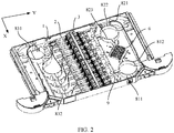
- FIG. 2 shows a structure of an integrated splicing and termination module 10 according to an embodiment of this application.
- the integrated splicing and termination module 10 includes a tray 1.
- the tray 1 is configured to carry a plurality of adapters 2, and the plurality of adapters 2 are mounted on a bracket 3.
- FIG. 3 shows a structure in which the integrated splicing and termination module 10 is pulled out according to an embodiment of this application.
- the bracket 3 includes a top plate 32, a bottom plate 33, and a plurality of side plates.
- the bracket 3 may be produced through integrated forming.
- the top plate 32 and the bottom plate 33 are disposed opposite to each other in the Z direction.
- the plurality of side plates are arranged in the X direction and are separately connected to the top plate 32 and the bottom plate 33 to form a plurality of cavities for accommodating the adapters 2.
- the adapters 2 are fixedly mounted in the cavities.
- the side plates include a first side plate 34 located at an edge of the top plate 32 and the bottom plate 33 and a second side plate 35 located between the top plate 32 and the bottom plate 33.
- the first side plate 34 is connected to the tray 1 to be mounted in the tray 1.
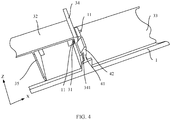
- FIG. 4 shows a specific structure of the bracket 3
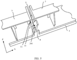
- FIG. 5 shows a structural form of a plurality of brackets 3.
- the integrated splicing and termination module 10 further includes a spacer plate 5.
- the spacer plate 5 is disposed on the tray 1.
- One end of the spacer plate 5 is connected to the tray 1, and the other end of the spacer plate 5 extends in the Z direction to separate the two brackets 3.
- the spacer plate 5 is connected to the first side plate 34 located on each of both sides of the spacer plate 5, so that the plurality of brackets 3 are mounted in the tray 1.
- a splicing operation is performed on a pigtail 71 and an optical fiber 72. Because the splicing operation or another operation performed in the tray 1 may affect cleanness of an end face of the adapter 2, the end face of the adapter needs to be detected and cleaned before the tray 1 is pushed back to the cabinet 01.
- a manner of mounting the bracket 3 in the tray 1 is changed, and a fixed connection between the bracket and the tray in the prior art is changed to a slidable connection between the bracket 3 and the tray 1.
- the bracket 3 is moved out of the tray 1 for operation when necessary, thereby ensuring required operation space.
- the bracket 3 is slidably mounted on the tray 1.
- the bracket 3 can be slidably connected to the tray 1 in a plurality of manners, for example, a slidable connection in which a sliding block cooperates with a sliding rail, and a connection in which a gear cooperates with a rack.
- FIG. 4 shows a connection structure between the bracket 3 and the tray 1.
- An embodiment of this application provides a manner of a guide rod and a guide groove.
- a guide rod 11 is disposed on the tray 1, and the guide rod 11 is fixedly disposed on the tray 1.
- a guide groove 31 matching the guide rod 11 is disposed on the bracket 3, and the guide groove 31 is specifically disposed on the first side plate 34.
- FIG. 5 shows a connection structure between two brackets 3 and the tray 1. To save space and facilitate mounting, guide rods 11 are separately disposed on two side faces of the spacer plate 5 that are opposite to each other in the X direction, and each guide rod 11 is correspondingly slidably connected to the guide groove 31 of the bracket 3.
- a structure of the guide groove 31 may be shown in FIG.
- the guide groove 31 may be provided as a through groove that penetrates through a thickness of the first side plate.
- the guide groove 31 may also be a groove having a specific depth. Different forms may be selected as the structure of the guide groove 31.
- the guide groove 31 is a slotted hole or may be a rectangular hole.
- the guide rod 11 is mounted in the guide groove 31, and a size of the guide rod 11 is smaller than a groove width of the guide groove 31, so that the guide groove 31 can slide relative to the guide rod 11, and the bracket 3 can slide relative to the tray 1 through relative movement between the guide rod 11 and the guide groove 31.
- the adapter 2 is driven to move up from the tray 1 by a distance in the Z direction, and then the end face of the adapter 2 is detected and cleaned, so that the device for cleaning and detecting the end face of the adapter 2 operates in relatively large space.
- an elastic hook 4 is further disposed on the tray 1, as shown in FIG. 4 , FIG. 5 , and FIG. 6 .
- FIG. 4 shows a structure of the elastic hook 4
- FIG. 5 shows a structural change of the elastic hook
- FIG. 6 shows a matching relationship between the elastic hook 4 and the bracket 3.
- One end of the elastic hook 4 is fixed in the tray 1, and the other end of the elastic hook 4 is clamped to the bracket 3.
- different forms may be selected for the elastic hook 4. As shown in FIG.
- the elastic hook 4 is a hook structure and includes a hook body 41 and a hook part 42. One end of the hook body 41 is connected to the tray 1, and the other end of the hook body 41 is connected to the hook part 42. One end that is of the hook part 42 and that is away from the hook body 41 is fastened on an end face 341 that is of the bracket 3 and that is away from the tray 1.
- the elastic hook 4 has elasticity to some extent, and may be prepared by using a plastic material, or may be prepared by using a rubber material. As shown in FIG.
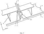
- FIG. 7 shows a position relationship between the bracket 3 and the elastic hook 4.
- the elastic hook 4 returns to an original position, the tray 1 and the elastic hook 4 are in contact, and the elastic hook 4 supports the bracket 3 to prevent the bracket 3 from falling down, that is, the sliding action of the bracket 3 ends.
- the end face of the adapter 2 may be cleaned and detected.
- the bracket 3 moves downward in the reverse direction of the Z direction under the guidance of the guide rod 11, the bracket 3 returns to the tray 1, and the bracket 3 is fastened when the elastic hook 4 is clamped to the bracket 3, as shown in FIG. 6 .
- the end face of the adapter can be detected and cleaned after the adapter 2 is moved to a proper height relative to the tray 1, without interfering with the structure of the tray 1, thereby facilitating detection and cleaning of the end face of the adapter 2.
- the structure of the device for cleaning and detecting the adapter 2 does not need to be changed, thereby reducing costs.
- the adapter 2 may be rotated by an angle on the basis of moving the adapter 2 in the Z direction, so that the adapter 2 is in a better position, where the angle may be 40° to 50°.
- two guide rods 11 may be disposed on the tray 1, and the two guide rods 11 are disposed opposite to each other in an extension direction parallel to the bracket 3.
- two guide rods 11 may be disposed on the tray 1, and two guide rods 11 are disposed on each of two side faces of the spacer plate in the X direction, to ensure that the two guide grooves 31 in each bracket 3 are slidably connected to the guide rod 31.
- the bracket 3 When the bracket 3 is rotated, the two guide rods 11 disposed opposite to each other are used as a rotation axis of rotating the bracket 3, the rotation axis is parallel to the X direction, and the bracket 3 may rotate around the rotation axis by a specific angle relative to the tray 1, which is more convenient for detection and cleaning of the end face of the adapter 2.
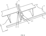
- FIG. 8 shows a position relationship between the bracket 3 and the elastic hook 4 after the sliding of the bracket 3 is completed.
- a surface that is of the hook part 42 and that is away from the hook body 41 is an inclined surface 421 facing the tray 1.
- the stopper 36 is disposed on the bracket 3 and is limited to be in the Z direction. A height of the stopper 36 is not less than a height of the bottom of the guide groove 31.
- the disposing of the stopper 36 can prevent the bracket 3 from falling down, and the stopper 36 cooperates with the inclined surface 421 to support the bracket 3. Therefore, the stopper 36 is disposed, so that when the bracket 3 slides to the specified position, a function of supporting the bracket 3 by the elastic hook 4 and the tray 1 can be better implemented.
- the integrated splicing and termination module 10 further includes a splicing card holder 6.
- FIG. 2 shows a specific structure of the splicing card holder 6
- FIG. 3 shows a connection relationship between the splicing card holder 6 and a cable.
- the splicing card holder 6 is fixedly disposed in the tray 1 to fasten the pigtail 71 and the optical fiber 72 to be spliced.
- One end of the pigtail 71 is mounted on the adapter 2, and the other end of the pigtail 71 enters the splicing card holder 6 for splicing.
- the optical fiber 72 penetrates into the tray 1 from an opening on a right side of the tray 1 and enters the splicing card holder 6 for splicing.
- the pigtail 71 and the optical fiber 72 to be spliced are fastened by using the splicing card holder 6, to facilitate a splicing operation and improve splicing efficiency.
- FIG. 2 shows a specific structure of a baffle plate 9, and FIG. 3 shows a position relationship between the baffle plate 9 and the tray 1.
- the integrated splicing and termination module 10 further includes the baffle plate 9.
- one end of the baffle plate 9 is connected to the tray 1, and the other end of the baffle plate 9 penetrates between the splicing card holder 6 and the adapter 2 and extends in the Z direction, to separate the splicing card holder 6 from the adapter 2.
- contaminants that are generated in a splicing operation and that are attached to the end surface of the adapter 2 can be reduced.
- a length of the baffle plate 9 is limited to be less than a length of the tray 1 in the X direction, to form a channel between a side face of the baffle plate 9 and the tray 1, where the channel is used to pass through the pigtail 71.
- FIG. 2 shows a specific structure of a guide structure 8, and FIG. 3 shows a position relationship between a cable 7 and the guide structure 8.
- the integrated splicing and termination module 10 further includes the guide structure 8, and the guide structure 8 is disposed on the tray 1.
- the guide structure 8 guides the cable 7 in the tray, and a split structure or an integrated structure may be used between the guide structure 8 and the integrated splicing and termination module 10.
- the first guide structure 81 may be fixedly connected to the integrated splicing and termination module 10 by means of bonding, welding, or a connecting piece (a bolt, a screw, or a rivet).
- the integrated splicing and termination module 10 may be produced through integrated forming.
- FIG. 2 shows a specific structure of a first guide structure 81
- FIG. 3 shows a position relationship between a pigtail 71 and the first guide structure 81.
- the guide structure 8 includes the first guide structure 81 configured to guide the pigtail 71 to a front side of the splicing card holder 6.
- the first guide structure 81 includes a first arc-shaped plate 811 and a second arc-shaped plate 812 that are disposed opposite to each other.
- the first arc-shaped plate 811 and the second arc-shaped plate 812 may be an integrated structure.
- the first arc-shaped plate 811 and the second arc-shaped plate 812 are produced through integrated forming.
- the first arc-shaped plate 811 and the second arc-shaped plate 812 may alternatively be separated structures.
- the first arc-shaped plate 811 and the second arc-shaped plate 812 may be connected or may not be connected.
- the first arc-shaped plate 811 and the second arc-shaped plate 812 are fixedly connected to the tray 1 separately, and adjacent ends of the second arc-shaped plate 812 and the first arc-shaped plate 811 may be in direct contact, or may be spaced by a specific gap.
- concave directions of the first arc-shaped plate 811 and the second arc-shaped plate 812 are limited to be opposite.
- An encircling feature used to guide the pigtail 71 is formed by using outer arc faces of the first arc-shaped plate 811 and the second arc-shaped plate 812.
- the pigtail 71 is bent and coiled according to the coiling feature, and then enters the splicing card holder 6 for splicing.
- radiuses of the first arc-shaped plate 811 and the second arc-shaped plate 812 should be greater than a minimum bending radius of the pigtail 71, and the minimum bending radius of the pigtail 71 is a minimum allowed bending radius without damaging the pigtail 71.
- shapes of the first arc-shaped plate 811 and the second arc-shaped plate 812 are not limited to the arc-shaped structures shown in FIG. 2 and FIG. 3 , and another form may be used, for example, an S-shaped structure or a U-shaped structure is used, provided that a bending direction of the pigtail 71 can be limited.
- FIG. 2 shows a specific structure of a second guide structure 82
- FIG. 3 shows a position relationship between the optical fiber 72 and the second guide structure 82.
- the guide structure 8 further includes the second guide structure 82 configured to guide the optical fiber 72 to a rear side of the splicing card holder 6.
- the second guide structure 82 includes a third arc-shaped plate 821, and a fourth arc-shaped plate 822 and a fifth arc-shaped plate 823 that are disposed opposite to each other.
- the third arc-shaped plate 821 is configured to guide the optical fiber 72 from an opening on a right side of the tray 1 to the tray 1.
- the third arc-shaped plate 821, the fourth arc-shaped plate 822, and the fifth arc-shaped plate 823 may be an integrated structure.
- the third arc-shaped plate 821, the fourth arc-shaped plate 822, and the fifth arc-shaped plate 823 are produced through integrated forming.
- the third arc-shaped plate 821, the fourth arc-shaped plate 822, and the fifth arc-shaped plate 823 may alternatively be separated structures. In this case, the third arc-shaped plate 821 and the fourth arc-shaped plate 822 may be connected or may not be connected.
- the third arc-shaped plate 821 and the fourth arc-shaped plate 822 are fixedly connected to the tray 1 separately, and adjacent ends of the third arc-shaped plate 821 and the fourth arc-shaped plate 822 may be in direct contact, or may be spaced by a specific gap.
- the fourth arc-shaped plate 822 and the fifth arc-shaped plate 823 may be connected or may not be connected.
- the fourth arc-shaped plate 822 and the fifth arc-shaped plate 823 are fixedly connected to the tray 1 separately, and adjacent ends of the fourth arc-shaped plate 822 and the fifth arc-shaped plate 823 may be in direct contact, or may be spaced by a specific gap.
- concave directions of the fourth arc-shaped plate 822 and the fifth arc-shaped plate 823 are limited to be opposite.
- An encircling feature used to guide the optical fiber 72 is formed by using outer arc faces of the fourth arc-shaped plate 822 and the fifth arc-shaped plate 823.
- the optical fiber 72 guided into the tray 1 by the third arc-shaped plate 821 is bent and coiled according to the coiling feature, and then enters the splicing card holder 6 for splicing.
- radiuses of the third arc-shaped plate 821, the fourth arc-shaped plate 822, and the fifth arc-shaped plate 823 should be greater than a minimum bending radius of the optical fiber 72.
- the minimum bending radius of the optical fiber 72 is a minimum allowed bending radius without damaging the optical fiber 72.
- shapes of the third arc-shaped plate 821, the fourth arc-shaped plate 822, and the fifth arc-shaped plate 823 are not limited to the arc-shaped structures shown in FIG. 2 and FIG. 3 , and another form may be used, for example, an S-shaped or a U-shaped structure is used, provided that a bending direction of the optical fiber 72 can be limited.
- FIG. 2 shows a specific structure of a third guide structure 83
- FIG. 3 shows a position relationship between a fiber patch cord 73 and the third guide structure 83.
- the guide structure 8 includes the third guide structure 83 configured to guide the fiber patch cord 73 to a side of the adapter 2.
- the third guide structure 83 includes a sixth arc-shaped plate 831 and at least one seventh arc-shaped plate 832.
- the sixth arc-shaped plate 831 and the seventh arc-shaped plate 832 may be an integrated structure.
- the sixth arc-shaped plate 831 and the seventh arc-shaped plate 832 are produced through integrated forming.
- the sixth arc-shaped plate 831 and the seventh arc-shaped plate 832 may alternatively be separated structures.
- the sixth arc-shaped plate 831 and the seventh arc-shaped plate 832 may be connected or may not be connected.
- the sixth arc-shaped plate 831 and the seventh arc-shaped plate 832 are fixedly connected to the tray 1 separately, and adjacent ends of the sixth arc-shaped plate 831 and the seventh arc-shaped plate 832 may be in direct contact, or may be spaced by a specific gap.
- concave directions of the sixth arc-shaped plate 831 and the seventh arc-shaped plate 832 are limited to be opposite.
- a channel is formed between outer arc faces of the sixth arc-shaped plate 831 and the seventh arc-shaped plate 832 and a side wall of the tray 1. The channel is connected to the opening on the left side of the tray 1, and is configured to accommodate the fiber patch cord 73 and guide the fiber patch cord 73 to the left end of the adapter 2.
- radiuses of the sixth arc-shaped plate 831 and the seventh arc-shaped plate 832 should be greater than a minimum bending radius of the fiber patch cord 73, and the minimum bending radius of the fiber patch cord 73 is a minimum allowed bending radius without damaging the fiber patch cord 73.
- shapes of the sixth arc-shaped plate 831 and the seventh arc-shaped plate 832 are not limited to the arc-shaped structures shown in FIG. 2 and FIG. 3 , and another form may be used, for example, an S-shaped structure or a U-shaped structure is used, provided that a bending direction of the fiber patch cord 73 can be limited.
- FIG. 1 is a schematic structural diagram of the communications device 00.
- the communications device 00 includes a cabinet 01, and a slot 02 is disposed on the cabinet 01.
- Each slot 02 is slidably connected to a drawer-like module, and the drawer-like module may be pulled into or pulled out from the slot 02.
- each drawer-like module includes the integrated splicing and termination module 10 according to any one of the foregoing implementations that is slidably assembled in the slot 02.
- the cabinet 01 is connected to the integrated splicing and termination module 10 by using a cable 7.
- two ends of the cable 7 are respectively connected to the cabinet 01 and the adapter 2, and the cable 7 is guided into two sides of the adapter 2 by using the guide structure 8.
- the end face of the adapter 2 can be detected and cleaned after the adapter 2 is moved to a proper height relative to the tray 1, without interfering with the structure of the tray 1, thereby facilitating detection and cleaning of the end face of the adapter 2.
- the structure of the device for cleaning and detecting the adapter 2 does not need to be changed, thereby reducing costs. Therefore, the communications device 00 having the integrated splicing and termination module 10 is universally applicable in consideration of manufacturing and using costs.
Landscapes
- Physics & Mathematics (AREA)
- General Physics & Mathematics (AREA)
- Optics & Photonics (AREA)
- Light Guides In General And Applications Therefor (AREA)
- Mechanical Coupling Of Light Guides (AREA)
Abstract
Description
- This application relates to the field of communications technologies, and in particular, to an integrated splicing and termination module and a communications device.
- In an optical distribution network, an adapter is configured to implement connection between different nodes of an optical cable. To ensure connection quality of an optical fiber, an end face of a connector that is in the adapter and that is used to connect a connection point needs to be detected and cleaned. According to a conventional method in the market, an end face detection device and an end face cleaning tool are used to directly align with the end face of the adapter for detection and cleaning.
- Currently, in an actual operation, adapters are fixedly designed in some modules due to functional requirements. For a single-layer adapter, a conventional device usually interferes with a mechanical part during end face detection and cleaning, and end face detection and cleaning cannot be performed. For a double-layer adapter or a multi-layer adapter, interference is more severe. Currently, a common method is to customize dedicated conversion adapters, detection devices, and cleaning devices. However, customization is unavoidably costly. Because an internal structure of the conversion adapter is complex and there is an optical device, a customization requirement is high. In addition, different conversion adapters need to be frequently replaced for different modules and cannot be produced on a large scale, and there is a defect that a device is prone to damage, and the like. Because different detection devices and cleaning devices are customized for modules with different functions, device compatibility is poor.
- This application provides an integrated splicing and termination module and a communications device, to resolve a problem of inconvenient detection and cleaning of an end face of an adapter.
- According to a first aspect, an example embodiment of this application provides an integrated splicing and termination module. The integrated splicing and termination module includes a tray, the tray is configured to carry a plurality of adapters, and the plurality of adapters are mounted on a bracket. To resolve the problem of inconvenient detection and cleaning of an end face of the adapter, in the integrated splicing and termination module in this application, a manner of mounting the bracket in the tray is changed. During specific disposing, the bracket in the integrated splicing and termination module is slidably mounted on the tray, so that the bracket may be moved out from the tray to detect and clean the end face of the adapter, and a device for cleaning and detecting the end face of the adapter operates in relatively large space. To control the sliding action of the bracket relative to the tray, an elastic hook is disposed on the tray, and the elastic hook is clamped to the bracket. When the end face of the adapter needs to be detected and cleaned, an operator exerts a force on the elastic hook, so that the elastic hook is away from the bracket, to unlock a sliding action of the bracket relative to the tray, and then moves out the bracket in a direction away from the tray. When the bracket slides to a specified position, the returned elastic hook cooperates with the tray to support the bracket, and the sliding action of the bracket ends. In this case, the end face of the adapter may be cleaned and detected. After the end face of the adapter is detected and cleaned, the operator exerts a force on the bracket in a direction towards the tray, the bracket returns to the tray, and the bracket is fastened when the elastic hook is clamped to the bracket. As can be learned from the foregoing description, by changing the manner of connecting the bracket and the tray and adding the elastic hook, the end face of the adapter can be detected and cleaned after the adapter is moved out, without interfering with the structure of the tray, thereby facilitating detection and cleaning of the end face of the adapter. In addition, the structure of the device for cleaning and detecting the adapter does not need to be changed, thereby reducing costs. In a specific implementation, at least one guide rod is disposed on the tray, a guide groove is disposed on the bracket, the guide rod is disposed in the guide groove, and the guide rod is slidably connected to the guide groove. The bracket is slidably connected to the tray by disposing the structural forms of the guide rod and the guide groove.
- In a specific implementation, the bracket includes a top plate and a bottom plate that are disposed opposite to each other, and a plurality of side plates. Every two of the side plates are connected to the top plate and the bottom plate to form a cavity used to mount the adapter. The guide groove is disposed on two side plates located at an edge of the top plate. The guide groove is disposed on the side plates to implement the slidable connection between the bracket and the tray, and a structure is simple.
- In a specific implementation, to help dispose a plurality of brackets, the integrated splicing and termination module further includes a spacer plate. The spacer plate is disposed on the tray and is configured to separate two brackets, the guide rod is disposed on two opposite side faces of the spacer plate, and one guide rod is slidably connected to the guide groove of one bracket. The plurality of brackets are slidably connected to the tray by using the spacer plate.
- In a specific implementation, two guide rods are disposed on the tray, the two guide rods are disposed opposite to each other in an extension direction parallel to the bracket, and the two guide rods are used as rotation axes to rotate the bracket after the bracket is moved out from the tray. This is more convenient for detection and cleaning of the end face of the adapter.
- In a specific implementation, different forms may be selected for the elastic hook. For example, the elastic hook is a hook structure and includes a hook body and a hook part. One end of the hook body is connected to the tray, the other end of the hook body is connected to the hook part, and one end that is of the hook part and that is away from the hook body is fastened on an end face that is of the bracket and that is away from the tray.
- In a specific implementation, a surface that is of the hook part and that is away from the hook body is an inclined surface facing the tray, a stopper is disposed on the bracket, and when the bracket slides to a specified position, the stopper cooperates with the inclined surface to support the bracket. The stopper is disposed, so that the elastic hook and the tray can better support the bracket when the bracket slides to the specified position.
- In a specific implementation, different forms may be selected for the guide groove. For example, the guide groove is a slotted hole in the direction away from the tray, and a height of the bottom of the slotted hole is not greater than a height of the stopper.
- In a specific implementation, to facilitate a splicing operation, the integrated splicing and termination module further includes a splicing card holder. The splicing card holder is disposed in the tray and is configured to fasten a pigtail and an optical fiber that are to be spliced, the pigtail is mounted at one end of the adapter, and the optical fiber penetrates into the tray from an opening of the tray.
- In a specific implementation, to improve a cabling manner of a cable in the tray, the integrated splicing and termination module further includes a guide structure. The guide structure is disposed on the tray, and includes a first guide structure configured to guide the pigtail to one side of the splicing card holder, and a second guide structure configured to guide the optical fiber to the other side of the splicing card holder. The first guide structure includes a first arc-shaped plate and a second arc-shaped plate that are disposed opposite to each other, and concave directions of the first arc-shaped plate and the second arc-shaped plate are opposite. The first arc-shaped plate and the second arc-shaped plate are disposed to form an encircling feature used to guide the pigtail. The second guide structure includes a third arc-shaped plate, and a fourth arc-shaped plate and a fifth arc-shaped plate that are disposed opposite to each other. The third arc-shaped plate is configured to guide the optical fiber from an opening on one side of the tray to the tray, and concave directions of the fourth arc-shaped plate and the fifth arc-shaped plate are opposite. The fourth arc-shaped plate and the fifth arc-shaped plate are disposed to form an encircling feature used to guide the optical fiber.
- In a specific implementation, to reduce pollution to the adapter caused by the splicing operation, the integrated splicing and termination module further includes a baffle plate. One end of the baffle plate is connected to the tray, and the other end of the baffle plate extends between the splicing card holder and the adapter to separate the splicing card holder from the adapter. In addition, a channel for passing the pigtail is disposed between a side face of the baffle plate and the tray, so that the pigtail passes through the channel.
- In a specific implementation, to improve a cabling manner of the cable in the tray, the guide mechanism further includes a third guide structure configured to guide a fiber patch cord to one side of the adapter. The third guide structure includes a sixth arc-shaped plate and at least one seventh arc-shaped plate, and concave directions of the sixth arc-shaped plate and the seventh arc-shaped plate are opposite. The sixth arc-shaped plate, the seventh arc-shaped plate, and the side wall of the tray form a channel that is connected to an opening on the other side of the tray and that is configured to accommodate the fiber patch cord, to guide the fiber patch cord to one end of the adapter. According to a second aspect, an example embodiment of this application provides a communications device. The communications device includes a cabinet, where a slot is disposed on the cabinet; and further includes a drawer-like module, where the drawer-like module includes the integrated splicing and termination module according to any one of the foregoing implementations that is slidably assembled in the slot. In addition, the cabinet is connected to the integrated splicing and termination module by using a cable, and the cable is guided into two sides of the adapter by using a guide structure. In the integrated splicing and termination module, a manner of connecting the bracket and the tray is changed and the elastic hook is added. Therefore, the end face of the adapter can be detected and cleaned after the adapter is moved out, and it is convenient to detect and clean the end face of the adapter. Therefore, the communications device having the integrated splicing and termination module is universally applicable in consideration of manufacturing and using costs.
-
-
FIG. 1 is a schematic structural diagram of a communications device according to an embodiment of this application; -
FIG. 2 is a schematic structural diagram of an integrated splicing and termination module according to an embodiment of this application; -
FIG. 3 is a schematic diagram of a structure in which the integrated splicing and termination module inFIG. 2 is pulled out; -
FIG. 4 is a schematic structural diagram of a bracket and a tray in an integrated splicing and termination module according to an embodiment of this application; -
FIG. 5 is a schematic diagram of a status in which a bracket is disconnected from a tray in an integrated splicing and termination module according to an embodiment of this application; -
FIG. 6 is another schematic structural diagram of a bracket and a tray in an integrated splicing and termination module according to an embodiment of this application; -
FIG. 7 is a schematic diagram of a status in which a bracket stops sliding in an integrated splicing and termination module according to an embodiment of this application; and -
FIG. 8 is another schematic diagram of a status in which a bracket stops sliding in an integrated splicing and termination module according to an embodiment of this application. - To make the objectives, technical solutions, and advantages of the present invention clearer, the following further describes the present invention in detail with reference to the accompanying drawings. Apparently, the described embodiments are merely some rather than all of the embodiments of the present invention. All other embodiments obtained by a person of ordinary skill in the art based on the embodiments of the present invention without creative efforts shall fall within the protection scope of the present invention.
- To help understand an integrated splicing and
termination module 10 provided in an embodiment of this application, the following first describes an application scenario of the integrated splicing andtermination module 10. An example embodiment of this application provides acommunications device 00.FIG. 1 is a schematic structural diagram of thecommunications device 00 according to an example embodiment of this application. Thecommunications device 00 includes acabinet 01. Aslot 02 is disposed on thecabinet 01, and a plurality of integrated splicing andtermination modules 10 are disposed in theslot 02. A plurality of adapters may be disposed in the integrated splicing andtermination module 10. The adapters are configured to implement connection of different nodes of an optical cable. Referring toFIG. 2 , the integrated splicing andtermination module 10 is applied in thecabinet 01 of thecommunications device 00. During disposing, to ensure connection quality of an optical fiber, an end face of a connector of the adapter needs to be detected and cleaned. However, because theadapter 2 is mounted in atray 1 by using abracket 3, space that can be used by a device for detecting and cleaning the end face to operate is relatively small. If the end face is detected and cleaned in the tray, the device for detecting and cleaning the end face interferes with the tray. To resolve the problem of inconvenient detection and cleaning of the end face of the adapter, a structure of the integrated splicing andtermination module 10 is improved in this embodiment of this application. The following describes in detail the integrated splicing andtermination module 10 provided in this embodiment of this application with reference to the accompanying drawings. For ease of description, it is assumed that a pull-out direction of the integrated splicing andtermination module 10 is an X direction, a width direction of thetray 1 is a Y direction, and a pull-out direction of the bracket is a Z direction. In the X direction, thetray 11 has front and rear sides. In the Y direction, thetray 11 has left and right sides. -
FIG. 2 shows a structure of an integrated splicing andtermination module 10 according to an embodiment of this application. The integrated splicing andtermination module 10 includes atray 1. Thetray 1 is configured to carry a plurality ofadapters 2, and the plurality ofadapters 2 are mounted on abracket 3.FIG. 3 shows a structure in which the integrated splicing andtermination module 10 is pulled out according to an embodiment of this application. Thebracket 3 includes atop plate 32, abottom plate 33, and a plurality of side plates. Thebracket 3 may be produced through integrated forming. Thetop plate 32 and thebottom plate 33 are disposed opposite to each other in the Z direction. The plurality of side plates are arranged in the X direction and are separately connected to thetop plate 32 and thebottom plate 33 to form a plurality of cavities for accommodating theadapters 2. Theadapters 2 are fixedly mounted in the cavities. The side plates include afirst side plate 34 located at an edge of thetop plate 32 and thebottom plate 33 and asecond side plate 35 located between thetop plate 32 and thebottom plate 33. Thefirst side plate 34 is connected to thetray 1 to be mounted in thetray 1.FIG. 4 shows a specific structure of thebracket 3, andFIG. 5 shows a structural form of a plurality ofbrackets 3. For ease of disposing the plurality ofbrackets 3, the integrated splicing andtermination module 10 further includes aspacer plate 5. Thespacer plate 5 is disposed on thetray 1. One end of thespacer plate 5 is connected to thetray 1, and the other end of thespacer plate 5 extends in the Z direction to separate the twobrackets 3. Thespacer plate 5 is connected to thefirst side plate 34 located on each of both sides of thespacer plate 5, so that the plurality ofbrackets 3 are mounted in thetray 1. - Still referring to
FIG. 3 , when the integrated splicing andtermination module 10 is pulled out, various operations may be performed in thetray 1, for example, a splicing operation is performed on apigtail 71 and anoptical fiber 72. Because the splicing operation or another operation performed in thetray 1 may affect cleanness of an end face of theadapter 2, the end face of the adapter needs to be detected and cleaned before thetray 1 is pushed back to thecabinet 01. However, to facilitate detection and cleaning of the end face of theadapter 2, in the integrated splicing andtermination module 10 provided in this embodiment of this application, a manner of mounting thebracket 3 in thetray 1 is changed, and a fixed connection between the bracket and the tray in the prior art is changed to a slidable connection between thebracket 3 and thetray 1. In this way, thebracket 3 is moved out of thetray 1 for operation when necessary, thereby ensuring required operation space. Thebracket 3 is slidably mounted on thetray 1. Thebracket 3 can be slidably connected to thetray 1 in a plurality of manners, for example, a slidable connection in which a sliding block cooperates with a sliding rail, and a connection in which a gear cooperates with a rack. -
FIG. 4 shows a connection structure between thebracket 3 and thetray 1. An embodiment of this application provides a manner of a guide rod and a guide groove. Aguide rod 11 is disposed on thetray 1, and theguide rod 11 is fixedly disposed on thetray 1. Aguide groove 31 matching theguide rod 11 is disposed on thebracket 3, and theguide groove 31 is specifically disposed on thefirst side plate 34.FIG. 5 shows a connection structure between twobrackets 3 and thetray 1. To save space and facilitate mounting, guiderods 11 are separately disposed on two side faces of thespacer plate 5 that are opposite to each other in the X direction, and eachguide rod 11 is correspondingly slidably connected to theguide groove 31 of thebracket 3. In addition, a structure of theguide groove 31 may be shown inFIG. 4 , and may be provided as a through groove that penetrates through a thickness of the first side plate. Certainly, theguide groove 31 may also be a groove having a specific depth. Different forms may be selected as the structure of theguide groove 31. For example, theguide groove 31 is a slotted hole or may be a rectangular hole. Theguide rod 11 is mounted in theguide groove 31, and a size of theguide rod 11 is smaller than a groove width of theguide groove 31, so that theguide groove 31 can slide relative to theguide rod 11, and thebracket 3 can slide relative to thetray 1 through relative movement between theguide rod 11 and theguide groove 31. In this way, theadapter 2 is driven to move up from thetray 1 by a distance in the Z direction, and then the end face of theadapter 2 is detected and cleaned, so that the device for cleaning and detecting the end face of theadapter 2 operates in relatively large space. - To ensure that the
bracket 3 can slide relative to thetray 1 only when thebracket 3 needs to move, and ensure that a sliding action of thebracket 3 relative to thetray 1 is controlled without detaching thebracket 3 from thetray 1, anelastic hook 4 is further disposed on thetray 1, as shown inFIG. 4 ,FIG. 5 , andFIG. 6 .FIG. 4 shows a structure of theelastic hook 4,FIG. 5 shows a structural change of the elastic hook, andFIG. 6 shows a matching relationship between theelastic hook 4 and thebracket 3. One end of theelastic hook 4 is fixed in thetray 1, and the other end of theelastic hook 4 is clamped to thebracket 3. During specific disposing, different forms may be selected for theelastic hook 4. As shown inFIG. 4 , theelastic hook 4 is a hook structure and includes ahook body 41 and ahook part 42. One end of thehook body 41 is connected to thetray 1, and the other end of thehook body 41 is connected to thehook part 42. One end that is of thehook part 42 and that is away from thehook body 41 is fastened on anend face 341 that is of thebracket 3 and that is away from thetray 1. Theelastic hook 4 has elasticity to some extent, and may be prepared by using a plastic material, or may be prepared by using a rubber material. As shown inFIG. 5 , when theelastic hook 4 is subjected to an action force in an F direction, theelastic hook 4 is away from theend face 341 of thebracket 3 in the X direction, so that theelastic hook 4 is detached from thebracket 3, and a clamp function is canceled. - The following describes an entire process of sliding the
bracket 3 relative to thetray 1. When the end face of theadapter 2 needs to be detected and cleaned, as shown inFIG. 5 , an operator exerts a force on theelastic hook 4. Thehook part 42 and thehook body 41 are deformed under the force. Driven by thehook body 41, thehook part 42 moves relative to thetray 1 in the X direction, and is detached from theend surface 341, so that theelastic hook 4 is far away from thebracket 3. In this case, the sliding action of thebracket 3 relative to thetray 1 is unlocked. An operator exerts an action force on the bracket in the Z direction, and thebracket 3 moves upwards in the Z direction under the guidance of theguide rod 11. - When the
bracket 3 slides to a specified height,FIG. 7 shows a position relationship between thebracket 3 and theelastic hook 4. Theelastic hook 4 returns to an original position, thetray 1 and theelastic hook 4 are in contact, and theelastic hook 4 supports thebracket 3 to prevent thebracket 3 from falling down, that is, the sliding action of thebracket 3 ends. In this case, the end face of theadapter 2 may be cleaned and detected. - After the end face of the
adapter 2 is detected and cleaned, the operator presses the bracket in the reverse direction of the Z direction. Thebracket 3 moves downward in the reverse direction of the Z direction under the guidance of theguide rod 11, thebracket 3 returns to thetray 1, and thebracket 3 is fastened when theelastic hook 4 is clamped to thebracket 3, as shown inFIG. 6 . - As can be learned from the foregoing description of the sliding process of the
bracket 3 relative to thetray 1, by changing the manner of connecting thebracket 3 and thetray 1 and adding theelastic hook 4, the end face of the adapter can be detected and cleaned after theadapter 2 is moved to a proper height relative to thetray 1, without interfering with the structure of thetray 1, thereby facilitating detection and cleaning of the end face of theadapter 2. In addition, the structure of the device for cleaning and detecting theadapter 2 does not need to be changed, thereby reducing costs. - To better clean and detect the end face of the
adapter 2, theadapter 2 may be rotated by an angle on the basis of moving theadapter 2 in the Z direction, so that theadapter 2 is in a better position, where the angle may be 40° to 50°. During specific disposing, when only onebracket 3 exists in thetray 1, twoguide rods 11 may be disposed on thetray 1, and the twoguide rods 11 are disposed opposite to each other in an extension direction parallel to thebracket 3. When a plurality ofbrackets 3 exist in the tray, twoguide rods 11 may be disposed on thetray 1, and twoguide rods 11 are disposed on each of two side faces of the spacer plate in the X direction, to ensure that the twoguide grooves 31 in eachbracket 3 are slidably connected to theguide rod 31. When thebracket 3 is rotated, the twoguide rods 11 disposed opposite to each other are used as a rotation axis of rotating thebracket 3, the rotation axis is parallel to the X direction, and thebracket 3 may rotate around the rotation axis by a specific angle relative to thetray 1, which is more convenient for detection and cleaning of the end face of theadapter 2. - To ensure that the
adapter 2 is in a stable state when the end face of theadapter 2 is detected and cleaned, astopper 36 cooperating with thehook part 42 is disposed on thebracket 3, to prevent thebracket 3 from falling down.FIG. 8 shows a position relationship between thebracket 3 and theelastic hook 4 after the sliding of thebracket 3 is completed. During specific disposing, a surface that is of thehook part 42 and that is away from thehook body 41 is aninclined surface 421 facing thetray 1. Thestopper 36 is disposed on thebracket 3 and is limited to be in the Z direction. A height of thestopper 36 is not less than a height of the bottom of theguide groove 31. When thebracket 3 slides to a specified position, the disposing of thestopper 36 can prevent thebracket 3 from falling down, and thestopper 36 cooperates with theinclined surface 421 to support thebracket 3. Therefore, thestopper 36 is disposed, so that when thebracket 3 slides to the specified position, a function of supporting thebracket 3 by theelastic hook 4 and thetray 1 can be better implemented. - During specific disposing, to facilitate a splicing operation, the integrated splicing and
termination module 10 further includes asplicing card holder 6.FIG. 2 shows a specific structure of thesplicing card holder 6, andFIG. 3 shows a connection relationship between thesplicing card holder 6 and a cable. Thesplicing card holder 6 is fixedly disposed in thetray 1 to fasten thepigtail 71 and theoptical fiber 72 to be spliced. One end of thepigtail 71 is mounted on theadapter 2, and the other end of thepigtail 71 enters thesplicing card holder 6 for splicing. Theoptical fiber 72 penetrates into thetray 1 from an opening on a right side of thetray 1 and enters thesplicing card holder 6 for splicing. Thepigtail 71 and theoptical fiber 72 to be spliced are fastened by using thesplicing card holder 6, to facilitate a splicing operation and improve splicing efficiency. -
FIG. 2 shows a specific structure of abaffle plate 9, andFIG. 3 shows a position relationship between thebaffle plate 9 and thetray 1. To reduce pollution to theadapter 2 caused by a splicing operation, the integrated splicing andtermination module 10 further includes thebaffle plate 9. During specific disposing, one end of thebaffle plate 9 is connected to thetray 1, and the other end of thebaffle plate 9 penetrates between thesplicing card holder 6 and theadapter 2 and extends in the Z direction, to separate thesplicing card holder 6 from theadapter 2. On one hand, contaminants that are generated in a splicing operation and that are attached to the end surface of theadapter 2 can be reduced. On the other hand, impact on thesplicing card holder 6, the splicedpigtail 71, and the splicedoptical fiber 72 can be further reduced when theadapter 2 is detected and cleaned. However, to prevent disposing of thebaffle plate 9 from affecting cabling of thepigtail 71, a length of thebaffle plate 9 is limited to be less than a length of thetray 1 in the X direction, to form a channel between a side face of thebaffle plate 9 and thetray 1, where the channel is used to pass through thepigtail 71. -
FIG. 2 shows a specific structure of aguide structure 8, andFIG. 3 shows a position relationship between acable 7 and theguide structure 8. The integrated splicing andtermination module 10 further includes theguide structure 8, and theguide structure 8 is disposed on thetray 1. Theguide structure 8 guides thecable 7 in the tray, and a split structure or an integrated structure may be used between theguide structure 8 and the integrated splicing andtermination module 10. When the split structure is used, thefirst guide structure 81 may be fixedly connected to the integrated splicing andtermination module 10 by means of bonding, welding, or a connecting piece (a bolt, a screw, or a rivet). When the integrated structure is used, the integrated splicing andtermination module 10 may be produced through integrated forming. -
FIG. 2 shows a specific structure of afirst guide structure 81, andFIG. 3 shows a position relationship between apigtail 71 and thefirst guide structure 81. To improve a cabling manner of thepigtail 71 in thetray 1 and avoid disorderly disposing of thepigtail 71 in thetray 1 and impact on a splicing operation, theguide structure 8 includes thefirst guide structure 81 configured to guide thepigtail 71 to a front side of thesplicing card holder 6. Thefirst guide structure 81 includes a first arc-shapedplate 811 and a second arc-shapedplate 812 that are disposed opposite to each other. The first arc-shapedplate 811 and the second arc-shapedplate 812 may be an integrated structure. In this case, the first arc-shapedplate 811 and the second arc-shapedplate 812 are produced through integrated forming. The first arc-shapedplate 811 and the second arc-shapedplate 812 may alternatively be separated structures. In this case, the first arc-shapedplate 811 and the second arc-shapedplate 812 may be connected or may not be connected. When the first arc-shapedplate 811 and the second arc-shapedplate 812 are not connected, the first arc-shapedplate 811 and the second arc-shapedplate 812 are fixedly connected to thetray 1 separately, and adjacent ends of the second arc-shapedplate 812 and the first arc-shapedplate 811 may be in direct contact, or may be spaced by a specific gap. In addition, concave directions of the first arc-shapedplate 811 and the second arc-shapedplate 812 are limited to be opposite. An encircling feature used to guide thepigtail 71 is formed by using outer arc faces of the first arc-shapedplate 811 and the second arc-shapedplate 812. Thepigtail 71 is bent and coiled according to the coiling feature, and then enters thesplicing card holder 6 for splicing. During specific setting, radiuses of the first arc-shapedplate 811 and the second arc-shapedplate 812 should be greater than a minimum bending radius of thepigtail 71, and the minimum bending radius of thepigtail 71 is a minimum allowed bending radius without damaging thepigtail 71. Certainly, shapes of the first arc-shapedplate 811 and the second arc-shapedplate 812 are not limited to the arc-shaped structures shown inFIG. 2 andFIG. 3 , and another form may be used, for example, an S-shaped structure or a U-shaped structure is used, provided that a bending direction of thepigtail 71 can be limited. -
FIG. 2 shows a specific structure of asecond guide structure 82, andFIG. 3 shows a position relationship between theoptical fiber 72 and thesecond guide structure 82. To improve a cabling manner of theoptical fiber 72 in thetray 1 and avoid disorderly disposing of theoptical fiber 72 in thetray 1 and impact on a splicing operation, theguide structure 8 further includes thesecond guide structure 82 configured to guide theoptical fiber 72 to a rear side of thesplicing card holder 6. Thesecond guide structure 82 includes a third arc-shapedplate 821, and a fourth arc-shapedplate 822 and a fifth arc-shapedplate 823 that are disposed opposite to each other. The third arc-shapedplate 821 is configured to guide theoptical fiber 72 from an opening on a right side of thetray 1 to thetray 1. The third arc-shapedplate 821, the fourth arc-shapedplate 822, and the fifth arc-shapedplate 823 may be an integrated structure. In this case, the third arc-shapedplate 821, the fourth arc-shapedplate 822, and the fifth arc-shapedplate 823 are produced through integrated forming. The third arc-shapedplate 821, the fourth arc-shapedplate 822, and the fifth arc-shapedplate 823 may alternatively be separated structures. In this case, the third arc-shapedplate 821 and the fourth arc-shapedplate 822 may be connected or may not be connected. When the third arc-shapedplate 821 and the fourth arc-shapedplate 822 are not connected, the third arc-shapedplate 821 and the fourth arc-shapedplate 822 are fixedly connected to thetray 1 separately, and adjacent ends of the third arc-shapedplate 821 and the fourth arc-shapedplate 822 may be in direct contact, or may be spaced by a specific gap. Similarly, the fourth arc-shapedplate 822 and the fifth arc-shapedplate 823 may be connected or may not be connected. When the fourth arc-shapedplate 822 and the fifth arc-shapedplate 823 are not connected, the fourth arc-shapedplate 822 and the fifth arc-shapedplate 823 are fixedly connected to thetray 1 separately, and adjacent ends of the fourth arc-shapedplate 822 and the fifth arc-shapedplate 823 may be in direct contact, or may be spaced by a specific gap. In addition, concave directions of the fourth arc-shapedplate 822 and the fifth arc-shapedplate 823 are limited to be opposite. An encircling feature used to guide theoptical fiber 72 is formed by using outer arc faces of the fourth arc-shapedplate 822 and the fifth arc-shapedplate 823. Theoptical fiber 72 guided into thetray 1 by the third arc-shapedplate 821 is bent and coiled according to the coiling feature, and then enters thesplicing card holder 6 for splicing. In specific setting, radiuses of the third arc-shapedplate 821, the fourth arc-shapedplate 822, and the fifth arc-shapedplate 823 should be greater than a minimum bending radius of theoptical fiber 72. The minimum bending radius of theoptical fiber 72 is a minimum allowed bending radius without damaging theoptical fiber 72. Certainly, shapes of the third arc-shapedplate 821, the fourth arc-shapedplate 822, and the fifth arc-shapedplate 823 are not limited to the arc-shaped structures shown inFIG. 2 andFIG. 3 , and another form may be used, for example, an S-shaped or a U-shaped structure is used, provided that a bending direction of theoptical fiber 72 can be limited. -
FIG. 2 shows a specific structure of athird guide structure 83, andFIG. 3 shows a position relationship between afiber patch cord 73 and thethird guide structure 83. To improve a cabling manner of thefiber patch cord 73 in thetray 1 and avoid disorderly disposing of thefiber patch cord 73 in thetray 1 and impact on a splicing operation, theguide structure 8 includes thethird guide structure 83 configured to guide thefiber patch cord 73 to a side of theadapter 2. Thethird guide structure 83 includes a sixth arc-shapedplate 831 and at least one seventh arc-shapedplate 832. The sixth arc-shapedplate 831 and the seventh arc-shapedplate 832 may be an integrated structure. In this case, the sixth arc-shapedplate 831 and the seventh arc-shapedplate 832 are produced through integrated forming. The sixth arc-shapedplate 831 and the seventh arc-shapedplate 832 may alternatively be separated structures. In this case, the sixth arc-shapedplate 831 and the seventh arc-shapedplate 832 may be connected or may not be connected. When the sixth arc-shapedplate 831 and the seventh arc-shapedplate 832 are not connected, the sixth arc-shapedplate 831 and the seventh arc-shapedplate 832 are fixedly connected to thetray 1 separately, and adjacent ends of the sixth arc-shapedplate 831 and the seventh arc-shapedplate 832 may be in direct contact, or may be spaced by a specific gap. In addition, concave directions of the sixth arc-shapedplate 831 and the seventh arc-shapedplate 832 are limited to be opposite. A channel is formed between outer arc faces of the sixth arc-shapedplate 831 and the seventh arc-shapedplate 832 and a side wall of thetray 1. The channel is connected to the opening on the left side of thetray 1, and is configured to accommodate thefiber patch cord 73 and guide thefiber patch cord 73 to the left end of theadapter 2. During specific setting, radiuses of the sixth arc-shapedplate 831 and the seventh arc-shapedplate 832 should be greater than a minimum bending radius of thefiber patch cord 73, and the minimum bending radius of thefiber patch cord 73 is a minimum allowed bending radius without damaging thefiber patch cord 73. Certainly, shapes of the sixth arc-shapedplate 831 and the seventh arc-shapedplate 832 are not limited to the arc-shaped structures shown inFIG. 2 andFIG. 3 , and another form may be used, for example, an S-shaped structure or a U-shaped structure is used, provided that a bending direction of thefiber patch cord 73 can be limited. - In addition, an embodiment of this application provides a
communications device 00.FIG. 1 is a schematic structural diagram of thecommunications device 00. Thecommunications device 00 includes acabinet 01, and aslot 02 is disposed on thecabinet 01. There may be one ormore slots 02, and when a plurality of slots are used, the plurality ofslots 02 are arranged in a height direction of thecabinet 01, that is, arranged in the Z direction. Eachslot 02 is slidably connected to a drawer-like module, and the drawer-like module may be pulled into or pulled out from theslot 02. During specific disposing, each drawer-like module includes the integrated splicing andtermination module 10 according to any one of the foregoing implementations that is slidably assembled in theslot 02. In addition, thecabinet 01 is connected to the integrated splicing andtermination module 10 by using acable 7. During connection, two ends of thecable 7 are respectively connected to thecabinet 01 and theadapter 2, and thecable 7 is guided into two sides of theadapter 2 by using theguide structure 8. As can be learned from the foregoing description, by changing the manner of connecting thebracket 3 and thetray 1 and adding theelastic hook 4 in the integrated splicing andtermination module 10, the end face of theadapter 2 can be detected and cleaned after theadapter 2 is moved to a proper height relative to thetray 1, without interfering with the structure of thetray 1, thereby facilitating detection and cleaning of the end face of theadapter 2. In addition, the structure of the device for cleaning and detecting theadapter 2 does not need to be changed, thereby reducing costs. Therefore, thecommunications device 00 having the integrated splicing andtermination module 10 is universally applicable in consideration of manufacturing and using costs. - The foregoing descriptions are merely specific implementations of this application, but are not intended to limit the protection scope of this application. Any variation or replacement readily figured out by a person skilled in the art within the technical scope disclosed in this application shall fall within the protection scope of this application. Therefore, the protection scope of this application shall be subject to the protection scope of the claims.
Claims (13)
- An integrated splicing and termination module, comprising a tray and a bracket on which an adapter is mounted, wherein an elastic hook is disposed on the tray, and the bracket is slidably mounted on the tray and is clamped to the elastic hook; when the elastic hook is detached from the bracket, the bracket slides in a direction away from the tray; and when the bracket slides to a specified position, the elastic hook cooperates with the tray to support the bracket.
- The integrated splicing and termination module according to claim 1, wherein at least one guide rod is disposed on the tray, a guide groove is disposed on the bracket, the guide rod is disposed in the guide groove, and the guide rod is slidably connected to the guide groove.
- The integrated splicing and termination module according to claim 2, wherein the bracket comprises a top plate and a bottom plate that are disposed opposite to each other, and a plurality of side plates, every two of the side plates are connected to the top plate and the bottom plate to form a cavity configured to mount the adapter, and the guide groove is disposed on two side plates located at an edge of the top plate.
- The integrated splicing and termination module according to claim 2 or 3, further comprising a spacer plate, wherein the spacer plate is disposed on the tray and is configured to separate two brackets, the guide rod is disposed on two opposite side faces of the spacer plate, and one guide rod is slidably connected to a guide groove of one bracket.
- The integrated splicing and termination module according to claim 2 or 3, wherein two guide rods are disposed on the tray, and the two guide rods are disposed opposite to each other in an extension direction parallel to the bracket.
- The integrated splicing and termination module according to any one of claims 1 to 5, wherein the elastic hook is a hook structure and comprises a hook body and a hook part; one end of the hook body is connected to the tray, and the other end is connected to the hook part; and one end that is of the hook part and that is away from the hook body is fastened on an end surface that is of the bracket and that is away from the tray.
- The integrated splicing and termination module according to claim 6, wherein a surface that is of the hook part and that is away from the hook body is an inclined surface facing the tray, a stopper is disposed on the bracket, and when the bracket slides to a specified position, the stopper cooperates with the inclined surface to support the bracket.
- The integrated splicing and termination module according to claim 7, wherein the guide groove is a slotted hole, and a height of the bottom of the slotted hole is not greater than a height of the stopper in the direction away from the tray.
- The integrated splicing and termination module according to any one of claims 1 to 8, further comprising a splicing card holder, wherein the splicing card holder is disposed in the tray and is configured to fasten a pigtail and an optical fiber that are to be spliced, the pigtail is mounted on one end of the adapter, and the optical fiber penetrates into the tray from an opening of the tray.
- The integrated splicing and termination module according to claim 9, further comprising a guide structure, wherein the guide structure is disposed on the tray, and comprises a first guide structure configured to guide the pigtail to one side of the splicing card holder, and a second guide structure configured to guide the optical fiber to the other side of the splicing card holder; wherein
the first guide structure comprises a first arc-shaped plate and a second arc-shaped plate that are disposed opposite to each other, and concave directions of the first arc-shaped plate and the second arc-shaped plate are opposite; and
the second guide structure comprises a third arc-shaped plate, and a fourth arc-shaped plate and a fifth arc-shaped plate that are disposed opposite to each other, the third arc-shaped plate is configured to guide the optical fiber from an opening on one side of the tray to the tray, and concave directions of the fourth arc-shaped plate and the fifth arc-shaped plate are opposite. - The integrated splicing and termination module according to claim 9 or 10, further comprising a baffle plate, wherein one end of the baffle plate is connected to the tray, and the other end of the baffle plate extends between the splicing card holder and the adapter to separate the splicing card holder from the adapter; and a channel for passing the pigtail is disposed between a side face of the baffle plate and the tray.
- The integrated splicing and termination module according to claim 10, wherein the guide mechanism further comprises a third guide structure configured to guide a fiber patch cord to one side of the adapter; the third guide structure comprises a sixth arc-shaped plate and at least one seventh arc-shaped plate, and concave directions of the sixth arc-shaped plate and the seventh arc-shaped plate are opposite; and the sixth arc-shaped plate, the seventh arc-shaped plate, and a side wall of the tray form a channel that is connected to an opening on the other side of the tray and that is configured to accommodate the fiber patch cord.
- A communications device, comprising:a cabinet, wherein a slot is disposed on the cabinet;a drawer-like module, comprising the integrated splicing and termination module according to any one of claims 1 to 12 that is slidably assembled in the slot; anda cable, wherein two ends of the cable are respectively connected to the cabinet, and the cable is guided to the adapter by using the guide structure.
Applications Claiming Priority (1)
| Application Number | Priority Date | Filing Date | Title |
|---|---|---|---|
| PCT/CN2019/077712 WO2020181470A1 (en) | 2019-03-11 | 2019-03-11 | Fusion-fit module and communication device |
Publications (3)
| Publication Number | Publication Date |
|---|---|
| EP3736614A1 true EP3736614A1 (en) | 2020-11-11 |
| EP3736614A4 EP3736614A4 (en) | 2021-03-03 |
| EP3736614B1 EP3736614B1 (en) | 2026-01-28 |
Family
ID=72427725
Family Applications (1)
| Application Number | Title | Priority Date | Filing Date |
|---|---|---|---|
| EP19906593.9A Active EP3736614B1 (en) | 2019-03-11 | 2019-03-11 | Fusion-fit module and communication device |
Country Status (3)
| Country | Link |
|---|---|
| EP (1) | EP3736614B1 (en) |
| CN (1) | CN112005148B (en) |
| WO (1) | WO2020181470A1 (en) |
Cited By (1)
| Publication number | Priority date | Publication date | Assignee | Title |
|---|---|---|---|---|
| US12487427B2 (en) | 2021-03-31 | 2025-12-02 | Afl Telecommunications Llc | Cable mounting clamps |
Families Citing this family (2)
| Publication number | Priority date | Publication date | Assignee | Title |
|---|---|---|---|---|
| CN114609731B (en) * | 2022-01-30 | 2023-07-18 | 华为技术有限公司 | Fusion module and communication equipment |
| CN118915256B (en) * | 2024-10-10 | 2025-03-21 | 杭州华宏通信设备有限公司 | Optical fiber distribution frame |
Family Cites Families (16)
| Publication number | Priority date | Publication date | Assignee | Title |
|---|---|---|---|---|
| US7171100B2 (en) * | 2004-11-03 | 2007-01-30 | Adc Telecommunications, Inc. | Optical fiber slack storage tray for distribution cabinet |
| CN201047880Y (en) * | 2007-06-14 | 2008-04-16 | 常州太平电器有限公司 | Integrated disk component for optical fibre distributing frame |
| CN101900856B (en) * | 2009-05-28 | 2012-06-27 | 华为技术有限公司 | Optical fiber socket |
| CN201518066U (en) * | 2009-09-24 | 2010-06-30 | 苏州新海宜通信科技股份有限公司 | Fiber fusing disc |
| CN102043201B (en) * | 2009-10-19 | 2012-10-03 | 泰科电子(上海)有限公司 | Optical fiber connecting device |
| RU2554300C2 (en) * | 2010-06-18 | 2015-06-27 | Адс Коммьюникейшнз (Шанхай) Ко., Лтд. | Fibre-optic terminal of distribution network and fibre distribution cable deployment method |
| US9075203B2 (en) * | 2012-01-17 | 2015-07-07 | Adc Telecommunications, Inc. | Fiber optic adapter block |
| EP3100090A4 (en) * | 2014-01-28 | 2017-09-06 | ADC Telecommunications Inc. | Slidable fiber optic connection module with cable slack management |
| WO2016029171A1 (en) * | 2014-08-21 | 2016-02-25 | Adc Telecommunications, Inc. | High density adapter carrier pack |
| HUE054230T2 (en) * | 2015-12-16 | 2021-08-30 | CommScope Connectivity Belgium BVBA | Telecommunication distribution elements |
| WO2017103234A1 (en) * | 2015-12-17 | 2017-06-22 | CommScope Connectivity Belgium BVBA | Telecommunications distribution elements |
| CN205715097U (en) * | 2016-04-21 | 2016-11-23 | 深圳市科信通信技术股份有限公司 | Adapter clip |
| CN206133063U (en) * | 2016-09-18 | 2017-04-26 | 中兴通讯股份有限公司 | Light is joined in marriage fibre web twine ODN and is melted and join in marriage structure of twining |
| WO2018058507A1 (en) * | 2016-09-30 | 2018-04-05 | 华为技术有限公司 | Optical fiber fusion module, optical fiber fusion frame |
| CN110462478B (en) * | 2017-04-04 | 2021-05-07 | 康普技术有限责任公司 | Optical Connectors and Termination Modules |
| CN207992515U (en) * | 2018-01-19 | 2018-10-19 | 西安高新科技职业学院 | Fiber box |
-
2019
- 2019-03-11 EP EP19906593.9A patent/EP3736614B1/en active Active
- 2019-03-11 CN CN201980003407.0A patent/CN112005148B/en active Active
- 2019-03-11 WO PCT/CN2019/077712 patent/WO2020181470A1/en not_active Ceased
Cited By (1)
| Publication number | Priority date | Publication date | Assignee | Title |
|---|---|---|---|---|
| US12487427B2 (en) | 2021-03-31 | 2025-12-02 | Afl Telecommunications Llc | Cable mounting clamps |
Also Published As
| Publication number | Publication date |
|---|---|
| EP3736614B1 (en) | 2026-01-28 |
| CN112005148B (en) | 2022-04-22 |
| CN112005148A (en) | 2020-11-27 |
| EP3736614A4 (en) | 2021-03-03 |
| WO2020181470A1 (en) | 2020-09-17 |
Similar Documents
| Publication | Publication Date | Title |
|---|---|---|
| EP3736614A1 (en) | Fusion-fit module and communication device | |
| US6398149B1 (en) | Cable management system with adjustable cable spools | |
| EP2333597B1 (en) | Fiber optic module assembly and associated methods | |
| CN102647877B (en) | Have support member communication shelf and in shelf the method for installation adapter panel | |
| US20110129186A1 (en) | Fiber Optic Module Assembly and Associated Methods | |
| US9500833B1 (en) | Optical fiber module rack system | |
| CN113534374B (en) | Optical fiber distribution equipment and optical fiber dispatching system | |
| JP7712404B2 (en) | Optical fiber distribution device, optical fiber scheduling method and system | |
| EP4236343B1 (en) | Patch panel with lifting cassette removal | |
| EP3845943A1 (en) | Welding module and communication device | |
| US10798845B2 (en) | 1U rackmount enclosure and 1U rack | |
| US20230068980A1 (en) | Fiber optic distribution frame | |
| US20100232757A1 (en) | Lc adapter | |
| EP3699658B1 (en) | Pull-out assembly | |
| JP2014112162A (en) | Optical connector, optical connector system, and optical backplane apparatus | |
| EP2828698A1 (en) | Pivotal support frame for a fiber optic adapter | |
| JP6005778B2 (en) | Optical connection structure | |
| WO2016154092A1 (en) | Fiber optic module and chassis with cable slack management | |
| CN219936153U (en) | Optical fiber distribution frame easy to disassemble and assemble | |
| CN218995722U (en) | Multi-station optical fiber jumper wire feeding clamp | |
| CN222850784U (en) | A guide rail mounting bracket for a fiber-to-the-home box | |
| CN117811667B (en) | Optical fiber automatic switching equipment and control method | |
| EP4266102A1 (en) | Fiber transportation tube holder | |
| CN216982022U (en) | Data acquisition gateway of numerical control machine tool | |
| CN214164587U (en) | Auxiliary device for drawing plane rectangular coordinate |
Legal Events
| Date | Code | Title | Description |
|---|---|---|---|
| STAA | Information on the status of an ep patent application or granted ep patent |
Free format text: STATUS: UNKNOWN |
|
| STAA | Information on the status of an ep patent application or granted ep patent |
Free format text: STATUS: THE INTERNATIONAL PUBLICATION HAS BEEN MADE |
|
| PUAI | Public reference made under article 153(3) epc to a published international application that has entered the european phase |
Free format text: ORIGINAL CODE: 0009012 |
|
| STAA | Information on the status of an ep patent application or granted ep patent |
Free format text: STATUS: REQUEST FOR EXAMINATION WAS MADE |
|
| 17P | Request for examination filed |
Effective date: 20200707 |
|
| AK | Designated contracting states |
Kind code of ref document: A1 Designated state(s): AL AT BE BG CH CY CZ DE DK EE ES FI FR GB GR HR HU IE IS IT LI LT LU LV MC MK MT NL NO PL PT RO RS SE SI SK SM TR |
|
| AX | Request for extension of the european patent |
Extension state: BA ME |
|
| A4 | Supplementary search report drawn up and despatched |
Effective date: 20210128 |
|
| RIC1 | Information provided on ipc code assigned before grant |
Ipc: G02B 6/44 20060101ALI20210122BHEP Ipc: G02B 6/255 20060101AFI20210122BHEP |
|
| DAV | Request for validation of the european patent (deleted) | ||
| DAX | Request for extension of the european patent (deleted) | ||
| STAA | Information on the status of an ep patent application or granted ep patent |
Free format text: STATUS: EXAMINATION IS IN PROGRESS |
|
| 17Q | First examination report despatched |
Effective date: 20230627 |
|
| REG | Reference to a national code |
Ref country code: DE Ref legal event code: R079 Ipc: G02B0006440000 Ref country code: DE Ref legal event code: R079 Ref document number: 602019080992 Country of ref document: DE Free format text: PREVIOUS MAIN CLASS: G02B0006255000 Ipc: G02B0006440000 |
|
| GRAP | Despatch of communication of intention to grant a patent |
Free format text: ORIGINAL CODE: EPIDOSNIGR1 |
|
| STAA | Information on the status of an ep patent application or granted ep patent |
Free format text: STATUS: GRANT OF PATENT IS INTENDED |
|
| RIC1 | Information provided on ipc code assigned before grant |
Ipc: G02B 6/44 20060101AFI20250909BHEP |
|
| INTG | Intention to grant announced |
Effective date: 20250925 |
|
| GRAS | Grant fee paid |
Free format text: ORIGINAL CODE: EPIDOSNIGR3 |
|
| GRAA | (expected) grant |
Free format text: ORIGINAL CODE: 0009210 |
|
| STAA | Information on the status of an ep patent application or granted ep patent |
Free format text: STATUS: THE PATENT HAS BEEN GRANTED |
|
| AK | Designated contracting states |
Kind code of ref document: B1 Designated state(s): AL AT BE BG CH CY CZ DE DK EE ES FI FR GB GR HR HU IE IS IT LI LT LU LV MC MK MT NL NO PL PT RO RS SE SI SK SM TR |
|
| REG | Reference to a national code |
Ref country code: CH Ref legal event code: F10 Free format text: ST27 STATUS EVENT CODE: U-0-0-F10-F00 (AS PROVIDED BY THE NATIONAL OFFICE) Effective date: 20260128 Ref country code: GB Ref legal event code: FG4D |
|
| REG | Reference to a national code |
Ref country code: DE Ref legal event code: R096 Ref document number: 602019080992 Country of ref document: DE |
|
| REG | Reference to a national code |
Ref country code: IE Ref legal event code: FG4D |
|
| PGFP | Annual fee paid to national office [announced via postgrant information from national office to epo] |
Ref country code: DE Payment date: 20260211 Year of fee payment: 8 |