EP3736525A2 - Exhaust valve for multiple start torpedo - Google Patents
Exhaust valve for multiple start torpedo Download PDFInfo
- Publication number
- EP3736525A2 EP3736525A2 EP19211661.4A EP19211661A EP3736525A2 EP 3736525 A2 EP3736525 A2 EP 3736525A2 EP 19211661 A EP19211661 A EP 19211661A EP 3736525 A2 EP3736525 A2 EP 3736525A2
- Authority
- EP
- European Patent Office
- Prior art keywords
- head
- torpedo
- seawater
- exhaust
- aft section
- Prior art date
- Legal status (The legal status is an assumption and is not a legal conclusion. Google has not performed a legal analysis and makes no representation as to the accuracy of the status listed.)
- Granted
Links
Images


Classifications
-
- F—MECHANICAL ENGINEERING; LIGHTING; HEATING; WEAPONS; BLASTING
- F42—AMMUNITION; BLASTING
- F42B—EXPLOSIVE CHARGES, e.g. FOR BLASTING, FIREWORKS, AMMUNITION
- F42B19/00—Marine torpedoes, e.g. launched by surface vessels or submarines; Sea mines having self-propulsion means
- F42B19/12—Propulsion specially adapted for torpedoes
- F42B19/24—Propulsion specially adapted for torpedoes by electric motors
-
- F—MECHANICAL ENGINEERING; LIGHTING; HEATING; WEAPONS; BLASTING
- F42—AMMUNITION; BLASTING
- F42B—EXPLOSIVE CHARGES, e.g. FOR BLASTING, FIREWORKS, AMMUNITION
- F42B19/00—Marine torpedoes, e.g. launched by surface vessels or submarines; Sea mines having self-propulsion means
- F42B19/12—Propulsion specially adapted for torpedoes
- F42B19/22—Propulsion specially adapted for torpedoes by internal-combustion engines
Definitions
- Exemplary embodiments pertain to the art of exhaust valves for multiple start torpedoes.
- Torpedoes power systems may be configured to start and stop to meet power demands.
- a multiple start torpedo including an aft body having an exhaust conduit defining a turbine end and a seawater end having an orifice.
- the multiple start torpedo includes an exhaust valve associated with the exhaust conduit including.
- the exhaust valve includes a fore section having a head and a valve stem.
- the exhaust valve includes an aft section tapered from the turbine end to the seawater end and defining a receptacle sized to receive the valve stem.
- the exhaust valve includes a biasing member disposed to bias the head in an extended position spaced apart from the aft section and abut the orifice in the extended position.
- further embodiments may include that the head defines a concave exterior surface and the orifice receives the concave exterior surface in the extended position.
- further embodiments may include that the head in a compressed position forms a teardrop shape with the aft section.
- further embodiments may include that the head defines a seawater catch basin oriented toward the seawater end such that seawater inflows drive the head toward the extended position.
- seawater catch basin has an outer surface that is substantially concave.
- further embodiments may include that the aft section is cropped on the seawater end.
- further embodiments may include that an exhaust valve diameter of the exhaust conduit is greater than an orifice diameter of the exhaust conduit.
- further embodiments may include that the aft section is suspended by stanchions along an axis of the exhaust conduit having the exhaust valve diameter.
- an exhaust valve diameter profile of the exhaust conduit is sized according to an outer profile of a teardrop shape formed by the head and the aft section in a compressed position.
- further embodiments may include that an exhaust valve cross-sectional exhaust area of the exhaust conduit and an orifice cross-sectional exhaust area of the exhaust conduit is same.
- a multiple start torpedo including an exhaust valve having a fore section having a head and a valve stem.
- the exhaust valve includes an aft section and defining a receptacle sized to receive the valve stem.
- the exhaust valve includes a biasing member having an extended position where the head is spaced apart from the aft section and a compressed position where the head and the aft section form a teardrop shape.
- further embodiments may include that the head forms an inner bulbous portion of the teardrop shape and the aft section forms an inner tail portion of the teardrop shape.
- further embodiments may include an aft body having an exhaust conduit defining a turbine end and a seawater end.
- further embodiments may include that the aft section is tapered toward the seawater end.
- further embodiments may include that the head defines a seawater catch basin oriented toward the seawater end such that seawater inflows drive the head toward the extended position.
- seawater catch basin has an outer surface that is substantially concave.
- further embodiments may include that the aft section is cropped on the seawater end.
- further embodiments may include that an exhaust valve diameter of the exhaust conduit is greater than an orifice diameter of the exhaust conduit.
- further embodiments may include that the aft section is suspended along an axis of the exhaust conduit.
- a multiple start torpedo including an exhaust valve having a fore section including a head defining a maximum outer diameter and a valve stem.
- the exhaust valve includes an aft section and defining a receptacle sized to receive the valve stem.
- the exhaust valve includes a biasing member having an extended position where the head is spaced apart from the aft section and a compressed position where the head and the aft section form an inner teardrop shape having an inner bulbous portion and an inner tail portion.
- the multiple start torpedo includes an exhaust conduit defining a seawater end and a turbine end, including an orifice defining an orifice diameter less than the maximum outer diameter such that the head is sized to block the orifice in the extended position, and including a contour having an outer teardrop shape that mimics the inner teardrop shape having an outer bulbous portion that joins the orifice toward the turbine end and an outer tail portion that extends toward the seawater end.
- a torpedo may include a propulsion system configured to propel the torpedo through a medium such as seawater.
- the propulsion system may be a hybrid electric propulsion system.
- Hybrid electric propulsion systems may allow a turbine or electric machine to propel the torpedo.
- the turbine may be used to charge an electric battery associated with the electric machine. After the battery has a full state of charge, the turbine is shut down, and the electric machine is used to propel the torpedo.
- An exhaust conduit associated with the turbine may guide exhaust from the turbine to exit the torpedo. The exhaust gas pressure may prevent seawater from entering portions of the exhaust conduit. When the turbine is shut down, seawater may enter the exhaust conduit and attempt to enter the turbine or other connected systems.
- the turbine may be started multiple times as required to charge the battery or propel the torpedo.
- An exhaust valve may be disposed on the exhaust conduit to prevent seawater from entering the turbine cavity or other connected systems.
- the exhaust valve may be configured as a check valve such that exhaust gases from the turbine are expelled from the torpedo and seawater is blocked from entering. Further, the exhaust valve may be operated by a solenoid or motor actuator to adjust positions of the valve.
- the exhaust valve may exert back pressure on the turbine, reducing efficiency.
- the exhaust valve geometry may be configured to minimize back pressure and increase turbine efficiency.
- the torpedo 100 includes a homing system 102 configured to navigate to targets.
- the torpedo 100 includes a warhead module 104.
- the torpedo 100 includes an electronics module for operating the torpedo 100 and the warhead module 104.
- the torpedo 100 includes fuel 110 and an oxidizer 108.
- the torpedo 100 may include a guidance wire spool 114.
- Propulsion electronics 116 operate the hybrid electric propulsion system 118.
- the hybrid electric propulsion system 118 includes a propulsion electric machine 122, a turbine 124 and a combustion chamber.
- the torpedo 100 includes an aft body 120.
- the aft body 120 included a propulsor and an exhaust conduit 126 attached to the turbine outlet.
- the torpedo aft body 120 includes an exhaust conduit 126 and an exhaust valve 128.
- the exhaust valve 128 may be disposed within the exhaust conduit 126.
- the exhaust conduit 126 defines an orifice 144 for configured to receive a fore section 132 of the exhaust valve 128. Upon receipt, the orifice 144 is blocked, preventing seawater from traversing the orifice 144 from the seawater end 138. As such, seawater or other mediums of travel for the torpedo 100 are prevented from entering the turbine end 140 attached to turbine 124.
- the exhaust valve 128 includes an aft section 130.
- the exhaust conduit 126 within torpedo aft body 120 is shown.
- the exhaust valve 128 is shown in a compressed position where fore section 132 meets or abuts the aft section 130.
- the aft section 130 tapers from the turbine end 140 to the seawater end 138, or from an inlet to an outlet of the exhaust conduit 126.
- the fore section 132 includes a head 134 and a valve stem 136.
- the valve stem 136 may be received by the aft section 130 and the head 134 may meet the aft section 130.
- the head 134 may have a concave exterior surface 146.
- the concave exterior surface 146 is curved to properly seat with the orifice 144 to block the backflow of seawater or other travel mediums from the seawater end 138.
- the head 134 in a compressed position forms a teardrop shape with the aft section 130.
- Teardrop shape may have a inner bulbous end 171 and inner tail end 169 corresponding to outer tail portion 168 of the exhaust conduit 126 and outer bulbous portion 170 of the exhaust conduit 126, respectively.
- the teardrop shape or similar shapes may form an aerodynamic exhaust valve 128 that has a reduced backpressure with respect to the attached turbine 124.
- the head 134 defines a seawater catch basin 148 that is oriented toward the seawater end 138. As seawater flows from the seawater end 138 toward the turbine 124, the head 134 is forced closed by the seawater received at the catch basin 148 or biasing member 142.
- the catch basin 148 may have any form configured to receive water or liquid.
- the catch basin 148 may have an outer surface configured to receive seawater.
- the outer surface may be concave similar to that of the outer surface of the head 134.
- the aft section 130 may include crop 150.
- the exhaust conduit 126 may have a nonuniform diameter. That is, the exhaust conduit 126 may have an orifice diameter 152 defining orifice 144.
- the exhaust conduit 126 may also have an exhaust valve diameter 154.
- the exhaust valve diameter 154 may be located in the vicinity of exhaust valve 128.
- the exhaust conduit 126 may also define an exhaust valve diameter profile 156 such that the exhaust conduit 126 mimics the teardrop shape of exhaust valve 128.
- the exhaust valve diameter profile 156 is substantially parallel with an outer profile of the exhaust valve 128 in the compressed position having a teardrop shape for a portion of the exhaust conduit 126 housing the exhaust valve 128. As such, the cross-sectional exhaust area.
- the exhaust valve diameter 154 may be greater than the orifice diameter 152.
- an exhaust valve 128 is shown in an extended position.
- Head 134 is shown abutting the orifice 144 in the extended position.
- the head 134 has a maximum outer diameter 166 that seals the orifice 144 in the extended position.
- the maximum outer diameter 166 is greater than the orifice diameter 152.
- the orifice 144 may be a fileted portion of the exhaust conduit 126 or an extension of the exhaust conduit 126 forming orifice diameter 152.
- the head 134 is shown blocking flow of fluid about the exhaust conduit 126.
- the aft section 130 includes a receptacle 162 for receiving the valve stem 136.
- the biasing member 142 biases the head 134 into the orifice 144 such that the head 134 is spaced apart from the aft section 130.
- the biasing member 142 may be any type of biasing device including springs, metal, motor operated actuators, or electromechanically actuated operations.
- the head 134 defines a seawater catch basin 148 that is oriented toward the seawater end 138. As seawater flows from the seawater end 138 toward the turbine 124, the head 134 is forced closed by the seawater received at the catch basin 148.
- the catch basin 148 may have any form configured to receive water or liquid.
- the catch basin 148 may have an outer surface configured to receive seawater. The outer surface may be concave similar to that of the outer surface of the head 134.
- the head 134 may have a concave exterior surface 146. The concave exterior surface 146 is curved to properly seat with the orifice 144 to block the backflow of seawater or other travel mediums from the seawater end 138
- a cross-section A-A is shown from a front aspect along an axis of the exhaust conduit 126.
- the aft section 130 of exhaust valve 128 is shown.
- the exhaust valve 128 includes biasing member 142 and valve stem receptacle 162.
- the aft section 130 is suspended from the exhaust conduit 126 by stanchions 160. Other suspension mechanisms may be employed, including mesh.
- a cross-sectional exhaust area 164 of the exhaust conduit 126 may be the same as the cross-sectional area of the orifice 144 cross-sectional exhaust area calculated as one half the orifice diameter 152 squared and multiplied by ⁇ .
Landscapes
- Engineering & Computer Science (AREA)
- Chemical & Material Sciences (AREA)
- Combustion & Propulsion (AREA)
- General Engineering & Computer Science (AREA)
- Exhaust Silencers (AREA)
- Lift Valve (AREA)
- Control Of Throttle Valves Provided In The Intake System Or In The Exhaust System (AREA)
- Control Of Turbines (AREA)
Abstract
Description
- Exemplary embodiments pertain to the art of exhaust valves for multiple start torpedoes. Torpedoes power systems may be configured to start and stop to meet power demands.
- Disclosed is a multiple start torpedo including an aft body having an exhaust conduit defining a turbine end and a seawater end having an orifice. The multiple start torpedo includes an exhaust valve associated with the exhaust conduit including. The exhaust valve includes a fore section having a head and a valve stem. The exhaust valve includes an aft section tapered from the turbine end to the seawater end and defining a receptacle sized to receive the valve stem. The exhaust valve includes a biasing member disposed to bias the head in an extended position spaced apart from the aft section and abut the orifice in the extended position.
- In addition to one or more of the features described above, or as an alternative, further embodiments may include that the head defines a concave exterior surface and the orifice receives the concave exterior surface in the extended position.
- In addition to one or more of the features described above, or as an alternative, further embodiments may include that the head in a compressed position forms a teardrop shape with the aft section.
- In addition to one or more of the features described above, or as an alternative, further embodiments may include that the head defines a seawater catch basin oriented toward the seawater end such that seawater inflows drive the head toward the extended position.
- In addition to one or more of the features described above, or as an alternative, further embodiments may include that the seawater catch basin has an outer surface that is substantially concave.
- In addition to one or more of the features described above, or as an alternative, further embodiments may include that the aft section is cropped on the seawater end.
- In addition to one or more of the features described above, or as an alternative, further embodiments may include that an exhaust valve diameter of the exhaust conduit is greater than an orifice diameter of the exhaust conduit.
- In addition to one or more of the features described above, or as an alternative, further embodiments may include that the aft section is suspended by stanchions along an axis of the exhaust conduit having the exhaust valve diameter.
- In addition to one or more of the features described above, or as an alternative, further embodiments may include that an exhaust valve diameter profile of the exhaust conduit is sized according to an outer profile of a teardrop shape formed by the head and the aft section in a compressed position.
- In addition to one or more of the features described above, or as an alternative, further embodiments may include that an exhaust valve cross-sectional exhaust area of the exhaust conduit and an orifice cross-sectional exhaust area of the exhaust conduit is same.
- Also disclosed is a multiple start torpedo including an exhaust valve having a fore section having a head and a valve stem. The exhaust valve includes an aft section and defining a receptacle sized to receive the valve stem. The exhaust valve includes a biasing member having an extended position where the head is spaced apart from the aft section and a compressed position where the head and the aft section form a teardrop shape.
- In addition to one or more of the features described above, or as an alternative, further embodiments may include that the head forms an inner bulbous portion of the teardrop shape and the aft section forms an inner tail portion of the teardrop shape.
- In addition to one or more of the features described above, or as an alternative, further embodiments may include an aft body having an exhaust conduit defining a turbine end and a seawater end.
- In addition to one or more of the features described above, or as an alternative, further embodiments may include that the aft section is tapered toward the seawater end.
- In addition to one or more of the features described above, or as an alternative, further embodiments may include that the head defines a seawater catch basin oriented toward the seawater end such that seawater inflows drive the head toward the extended position.
- In addition to one or more of the features described above, or as an alternative, further embodiments may include that the seawater catch basin has an outer surface that is substantially concave.
- In addition to one or more of the features described above, or as an alternative, further embodiments may include that the aft section is cropped on the seawater end.
- In addition to one or more of the features described above, or as an alternative, further embodiments may include that an exhaust valve diameter of the exhaust conduit is greater than an orifice diameter of the exhaust conduit.
- In addition to one or more of the features described above, or as an alternative, further embodiments may include that the aft section is suspended along an axis of the exhaust conduit.
- Also disclosed is a multiple start torpedo including an exhaust valve having a fore section including a head defining a maximum outer diameter and a valve stem. The exhaust valve includes an aft section and defining a receptacle sized to receive the valve stem. The exhaust valve includes a biasing member having an extended position where the head is spaced apart from the aft section and a compressed position where the head and the aft section form an inner teardrop shape having an inner bulbous portion and an inner tail portion. The multiple start torpedo includes an exhaust conduit defining a seawater end and a turbine end, including an orifice defining an orifice diameter less than the maximum outer diameter such that the head is sized to block the orifice in the extended position, and including a contour having an outer teardrop shape that mimics the inner teardrop shape having an outer bulbous portion that joins the orifice toward the turbine end and an outer tail portion that extends toward the seawater end.
- The following descriptions should not be considered limiting in any way. With reference to the accompanying drawings, like elements are numbered alike:
-
FIG. 1 is a system diagram for a hybrid electric torpedo; -
FIG. 2 is a cross-sectional side view of an exhaust conduit for a torpedo propulsion system; -
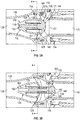
FIG. 3A is a cross-sectional side view of an exhaust valve in an extended position within an exhaust conduit of the hybrid electric torpedo; -
FIG. 3B is a cross-sectional side view of an exhaust valve of an exhaust conduit in a compressed position within an exhaust conduit of the hybrid electric torpedo; and -
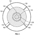
FIG. 4 is a cross-sectional front view of an exhaust valve of an exhaust conduit. - A detailed description of one or more embodiments of the disclosed apparatus and method are presented herein by way of exemplification and not limitation with reference to the Figures.
- A torpedo may include a propulsion system configured to propel the torpedo through a medium such as seawater. The propulsion system may be a hybrid electric propulsion system. Hybrid electric propulsion systems may allow a turbine or electric machine to propel the torpedo. The turbine may be used to charge an electric battery associated with the electric machine. After the battery has a full state of charge, the turbine is shut down, and the electric machine is used to propel the torpedo. An exhaust conduit associated with the turbine may guide exhaust from the turbine to exit the torpedo. The exhaust gas pressure may prevent seawater from entering portions of the exhaust conduit. When the turbine is shut down, seawater may enter the exhaust conduit and attempt to enter the turbine or other connected systems. The turbine may be started multiple times as required to charge the battery or propel the torpedo.
- An exhaust valve may be disposed on the exhaust conduit to prevent seawater from entering the turbine cavity or other connected systems. The exhaust valve may be configured as a check valve such that exhaust gases from the turbine are expelled from the torpedo and seawater is blocked from entering. Further, the exhaust valve may be operated by a solenoid or motor actuator to adjust positions of the valve. The exhaust valve may exert back pressure on the turbine, reducing efficiency. The exhaust valve geometry may be configured to minimize back pressure and increase turbine efficiency.
- Referring to
FIG. 1 atorpedo 100 is shown. Thetorpedo 100 includes ahoming system 102 configured to navigate to targets. Thetorpedo 100 includes awarhead module 104. Thetorpedo 100 includes an electronics module for operating thetorpedo 100 and thewarhead module 104. Thetorpedo 100 includesfuel 110 and anoxidizer 108. Thetorpedo 100 may include aguidance wire spool 114.Propulsion electronics 116 operate the hybridelectric propulsion system 118. The hybridelectric propulsion system 118 includes a propulsionelectric machine 122, aturbine 124 and a combustion chamber. Thetorpedo 100 includes anaft body 120. Theaft body 120 included a propulsor and anexhaust conduit 126 attached to the turbine outlet. - Referring to
FIG. 2 , the torpedo aftbody 120 is shown. Theaft body 120 includes anexhaust conduit 126 and anexhaust valve 128. Theexhaust valve 128 may be disposed within theexhaust conduit 126. Theexhaust conduit 126 defines anorifice 144 for configured to receive afore section 132 of theexhaust valve 128. Upon receipt, theorifice 144 is blocked, preventing seawater from traversing theorifice 144 from theseawater end 138. As such, seawater or other mediums of travel for thetorpedo 100 are prevented from entering theturbine end 140 attached toturbine 124. Theexhaust valve 128 includes anaft section 130. - Referring to
FIG. 3A , theexhaust conduit 126 within torpedo aftbody 120 is shown. Theexhaust valve 128 is shown in a compressed position wherefore section 132 meets or abuts theaft section 130. Theaft section 130, as shown, tapers from theturbine end 140 to theseawater end 138, or from an inlet to an outlet of theexhaust conduit 126. Thefore section 132 includes ahead 134 and avalve stem 136. The valve stem 136 may be received by theaft section 130 and thehead 134 may meet theaft section 130. Thehead 134 may have a concaveexterior surface 146. The concaveexterior surface 146 is curved to properly seat with theorifice 144 to block the backflow of seawater or other travel mediums from theseawater end 138. - As shown, the
head 134 in a compressed position forms a teardrop shape with theaft section 130. Teardrop shape may have a innerbulbous end 171 andinner tail end 169 corresponding toouter tail portion 168 of theexhaust conduit 126 and outerbulbous portion 170 of theexhaust conduit 126, respectively. The teardrop shape or similar shapes may form anaerodynamic exhaust valve 128 that has a reduced backpressure with respect to the attachedturbine 124. Thehead 134 defines aseawater catch basin 148 that is oriented toward theseawater end 138. As seawater flows from theseawater end 138 toward theturbine 124, thehead 134 is forced closed by the seawater received at thecatch basin 148 or biasingmember 142. Thecatch basin 148 may have any form configured to receive water or liquid. Thecatch basin 148 may have an outer surface configured to receive seawater. The outer surface may be concave similar to that of the outer surface of thehead 134. Theaft section 130 may includecrop 150. Theexhaust conduit 126 may have a nonuniform diameter. That is, theexhaust conduit 126 may have anorifice diameter 152 definingorifice 144. Theexhaust conduit 126 may also have anexhaust valve diameter 154. Theexhaust valve diameter 154 may be located in the vicinity ofexhaust valve 128. Theexhaust conduit 126 may also define an exhaustvalve diameter profile 156 such that theexhaust conduit 126 mimics the teardrop shape ofexhaust valve 128. That is, the exhaustvalve diameter profile 156 is substantially parallel with an outer profile of theexhaust valve 128 in the compressed position having a teardrop shape for a portion of theexhaust conduit 126 housing theexhaust valve 128. As such, the cross-sectional exhaust area. Theexhaust valve diameter 154 may be greater than theorifice diameter 152. - Referring to
FIG. 3AB , anexhaust valve 128 is shown in an extended position.Head 134 is shown abutting theorifice 144 in the extended position. Thehead 134 has a maximumouter diameter 166 that seals theorifice 144 in the extended position. The maximumouter diameter 166 is greater than theorifice diameter 152. Theorifice 144 may be a fileted portion of theexhaust conduit 126 or an extension of theexhaust conduit 126 formingorifice diameter 152. Thehead 134 is shown blocking flow of fluid about theexhaust conduit 126. Theaft section 130 includes areceptacle 162 for receiving thevalve stem 136. As shown, the biasingmember 142 biases thehead 134 into theorifice 144 such that thehead 134 is spaced apart from theaft section 130. The biasingmember 142 may be any type of biasing device including springs, metal, motor operated actuators, or electromechanically actuated operations. Thehead 134 defines aseawater catch basin 148 that is oriented toward theseawater end 138. As seawater flows from theseawater end 138 toward theturbine 124, thehead 134 is forced closed by the seawater received at thecatch basin 148. Thecatch basin 148 may have any form configured to receive water or liquid. Thecatch basin 148 may have an outer surface configured to receive seawater. The outer surface may be concave similar to that of the outer surface of thehead 134. Thehead 134 may have a concaveexterior surface 146. The concaveexterior surface 146 is curved to properly seat with theorifice 144 to block the backflow of seawater or other travel mediums from theseawater end 138. - Referring to
FIG. 4 , a cross-section A-A is shown from a front aspect along an axis of theexhaust conduit 126. Theaft section 130 ofexhaust valve 128 is shown. Theexhaust valve 128 includes biasingmember 142 and valve stemreceptacle 162. Theaft section 130 is suspended from theexhaust conduit 126 bystanchions 160. Other suspension mechanisms may be employed, including mesh. Across-sectional exhaust area 164 of theexhaust conduit 126 may be the same as the cross-sectional area of theorifice 144 cross-sectional exhaust area calculated as one half theorifice diameter 152 squared and multiplied by π. - The term "about" is intended to include the degree of error associated with measurement of the particular quantity based upon the equipment available at the time of filing the application.
- The terminology used herein is for the purpose of describing particular embodiments only and is not intended to be limiting of the present disclosure. As used herein, the singular forms "a", "an" and "the" are intended to include the plural forms as well, unless the context clearly indicates otherwise. It will be further understood that the terms "comprises" and/or "comprising," when used in this specification, specify the presence of stated features, integers, steps, operations, elements, and/or components, but do not preclude the presence or addition of one or more other features, integers, steps, operations, element components, and/or groups thereof.
- While the present disclosure has been described with reference to an exemplary embodiment or embodiments, it will be understood by those skilled in the art that various changes may be made and equivalents may be substituted for elements thereof without departing from the scope of the invention as defined by the claims. In addition, many modifications may be made to adapt a particular situation or material to the teachings of the present disclosure without departing from the scope of the invention. Therefore, it is intended that the present disclosure not be limited to the particular embodiment disclosed as the best mode contemplated for carrying out this present disclosure, but that the present disclosure will include all embodiments falling within the scope of the claims.
Claims (15)
- A multiple start torpedo comprising:an aft body (120) having an exhaust conduit (126) defining a turbine end (140) and a seawater end (138) having an orifice (144); andan exhaust valve (128) associated with the exhaust conduit including:a fore section (132) having a head (134) and a valve stem (136);an aft section (130) tapered from the turbine end to the seawater end and defining a receptacle sized to receive the valve stem; anda biasing member (142) disposed to bias the head in an extended position spaced apart from the aft section and abut the orifice in the extended position.
- The multiple start torpedo of claim 1, wherein the head (134) defines a concave exterior surface (146) and the orifice (144) receives the concave exterior surface in the extended position.
- The multiple start torpedo of claim 2, wherein the head in a compressed position forms a teardrop shape with the aft section.
- The multiple start torpedo of claim 2, wherein the head defines a seawater catch basin (148) oriented toward the seawater end such that seawater inflows drive the head toward the extended position, and preferably wherein the seawater catch basin has an outer surface that is substantially concave.
- The multiple start torpedo of any preceding claim, wherein the aft section is cropped on the seawater end.
- The multiple start torpedo of any preceding claim, wherein an exhaust valve diameter of the exhaust conduit is greater than an orifice diameter of the exhaust conduit.
- The multiple start torpedo of claim 6, wherein the aft section is suspended by stanchions along an axis of the exhaust conduit having the exhaust valve diameter.
- The multiple start torpedo of claim 6, wherein an exhaust valve diameter profile of the exhaust conduit is sized according to an outer profile of a teardrop shape formed by the head and the aft section in a compressed position, or wherein an exhaust valve cross-sectional exhaust area of the exhaust conduit and an orifice cross-sectional exhaust area of the exhaust conduit is the same.
- A multiple start torpedo comprising:
an exhaust valve (128) includinga fore section (132) having a head (134) and a valve stem (136),an aft section (130) and defining a receptacle sized to receive the valve stem, anda biasing member (142) having an extended position where the head is spaced apart from the aft section and a compressed position where the head and the aft section form a teardrop shape. - The multiple start torpedo of claim 9, wherein the head forms an inner bulbous portion (171) of the teardrop shape and the aft section forms an inner tail portion (169) of the teardrop shape.
- The multiple start torpedo of claim 10 further comprising, an aft body (120) having an exhaust conduit (126) defining a turbine end (140) and a seawater end (138), and preferably wherein the aft section is tapered toward the seawater end.
- The multiple start torpedo of claim 11, wherein the head defines a seawater catch basin (148) oriented toward the seawater end such that seawater inflows drive the head toward the extended position, and optionally wherein the seawater catch basin has an outer surface that is substantially concave.
- The multiple start torpedo of claim 11 or 12, wherein the aft section is cropped on the seawater end and/or wherein the aft section is suspended along an axis of the exhaust conduit.
- The multiple start torpedo of claim 11, 12 or 13, wherein an exhaust valve diameter of the exhaust conduit is greater than an orifice diameter of the exhaust conduit.
- A multiple start torpedo comprising:
an exhaust valve (128) including:a fore section (132) including a head (134) defining a maximum outer diameter and a valve stem (136);an aft section (130) and defining a receptacle sized to receive the valve stem; anda biasing member (142) having an extended position where the head is spaced apart from the aft section and a compressed position where the head and the aft section form an inner teardrop shape having an inner bulbous portion and an inner tail portion; andan exhaust conduit (126) defining a seawater end and a turbine end, including an orifice defining an orifice diameter less than the maximum outer diameter such that the head is sized to block the orifice in the extended position, and including a contour having an outer teardrop shape that mimics the inner teardrop shape having an outer bulbous portion that joins the orifice toward the turbine end and an outer tail portion that extends toward the seawater end.
Applications Claiming Priority (1)
| Application Number | Priority Date | Filing Date | Title |
|---|---|---|---|
| US16/409,466 US10914562B2 (en) | 2019-05-10 | 2019-05-10 | Exhaust valve for multiple start torpedo |
Publications (3)
| Publication Number | Publication Date |
|---|---|
| EP3736525A2 true EP3736525A2 (en) | 2020-11-11 |
| EP3736525A3 EP3736525A3 (en) | 2020-11-18 |
| EP3736525B1 EP3736525B1 (en) | 2022-03-23 |
Family
ID=68699228
Family Applications (1)
| Application Number | Title | Priority Date | Filing Date |
|---|---|---|---|
| EP19211661.4A Active EP3736525B1 (en) | 2019-05-10 | 2019-11-26 | Exhaust valve for multiple start torpedo |
Country Status (2)
| Country | Link |
|---|---|
| US (1) | US10914562B2 (en) |
| EP (1) | EP3736525B1 (en) |
Family Cites Families (10)
| Publication number | Priority date | Publication date | Assignee | Title |
|---|---|---|---|---|
| FR397532A (en) | 1908-02-21 | 1909-05-10 | Harold Waldron Shonnard | Improvements to torpedoes |
| FR700749A (en) | 1929-08-30 | 1931-03-06 | Silurificio Whitehead Di Fiume | Device for discharging compressed air from the tank of self-propelled torpedoes when they tend to descend beyond a determined depth |
| US2938485A (en) * | 1945-03-31 | 1960-05-31 | William A Riley | Power transmission apparatus for torpedoes |
| FR2234500B1 (en) | 1973-06-25 | 1978-03-03 | Socla | |
| US4346662A (en) * | 1980-05-07 | 1982-08-31 | The United States Of America As Represented By The Secretary Of The Navy | Self-contained backflush/start system for suction LFC undersea vehicle |
| US4359957A (en) * | 1981-01-28 | 1982-11-23 | Trw Inc. | Torpedo and operating method |
| US5097993A (en) * | 1990-11-27 | 1992-03-24 | W.A. Lane, Inc. | Pouch packaging machine fill tube and plunger rod assembly |
| US5291731A (en) * | 1993-03-23 | 1994-03-08 | The United States Of America As Represented By The Secretary Of The Navy | Torpedo with external combustion engine having an expansion chamber |
| US5561276A (en) * | 1995-10-30 | 1996-10-01 | The United States Of America As Represented By The Secretary Of The Navy | Two-phase-flow muffler in a rotating shaft |
| US6796260B1 (en) | 2003-09-08 | 2004-09-28 | The United States Of America As Represented By The Secretary Of The Navy | Elastomeric ejection system with acoustically improved check valve |
-
2019
- 2019-05-10 US US16/409,466 patent/US10914562B2/en active Active
- 2019-11-26 EP EP19211661.4A patent/EP3736525B1/en active Active
Also Published As
| Publication number | Publication date |
|---|---|
| EP3736525B1 (en) | 2022-03-23 |
| US10914562B2 (en) | 2021-02-09 |
| US20200355481A1 (en) | 2020-11-12 |
| EP3736525A3 (en) | 2020-11-18 |
Similar Documents
| Publication | Publication Date | Title |
|---|---|---|
| US8128056B2 (en) | Flow control valve | |
| EP2778039B1 (en) | Air supply device for air-lubricated ship | |
| EP3008308B1 (en) | Pneumatic compressor recirculation valve system | |
| DE69915493D1 (en) | CARTRIDGE FOR SELF LOADING ARMS | |
| EP3056689B1 (en) | Governing valve device and power generating equipment | |
| EP3061935A1 (en) | Engine with supercharger | |
| FR3017655A1 (en) | TURBOREACTOR COMPRISING A SAMPLING SYSTEM FOR TAKING AIR INTO THE TURBOREACTOR | |
| SE1100435A1 (en) | Pressure Pulse Generator | |
| EP3008324B1 (en) | Pneumatic compressor recirculation valve system for limitation of surge | |
| PL173444B1 (en) | Pneumatic gun for removing adhering particulate deposits and cuild-ups | |
| JP2008128150A (en) | Ejector and negative pressure supply device for brake booster using the same | |
| US20200040812A1 (en) | Turbocharger | |
| EP3736525B1 (en) | Exhaust valve for multiple start torpedo | |
| US3392693A (en) | Method of and means for reducing drag | |
| EP3324029B1 (en) | Pressure regulator | |
| US6796772B2 (en) | Ejector and negative-pressure supply apparatus using the same | |
| JPH01502046A (en) | solenoid valve | |
| EP1455084B1 (en) | Check valve for fuel pump | |
| JP6427435B2 (en) | Pressure type actuator | |
| US20030034073A1 (en) | Check valve for fuel pump | |
| CN108071466B (en) | Exhaust system for an internal combustion engine and method for controlling the same | |
| KR101684910B1 (en) | Control Valve for Variable Ballast System of Under Water Submersible | |
| US4817889A (en) | Foolproof simplified vacuum systems | |
| JP6270838B2 (en) | Engine system and ship | |
| KR20160031144A (en) | Underwater weapon launch apparatus and method |
Legal Events
| Date | Code | Title | Description |
|---|---|---|---|
| PUAI | Public reference made under article 153(3) epc to a published international application that has entered the european phase |
Free format text: ORIGINAL CODE: 0009012 |
|
| STAA | Information on the status of an ep patent application or granted ep patent |
Free format text: STATUS: THE APPLICATION HAS BEEN PUBLISHED |
|
| PUAL | Search report despatched |
Free format text: ORIGINAL CODE: 0009013 |
|
| AK | Designated contracting states |
Kind code of ref document: A2 Designated state(s): AL AT BE BG CH CY CZ DE DK EE ES FI FR GB GR HR HU IE IS IT LI LT LU LV MC MK MT NL NO PL PT RO RS SE SI SK SM TR |
|
| AK | Designated contracting states |
Kind code of ref document: A3 Designated state(s): AL AT BE BG CH CY CZ DE DK EE ES FI FR GB GR HR HU IE IS IT LI LT LU LV MC MK MT NL NO PL PT RO RS SE SI SK SM TR |
|
| RIC1 | Information provided on ipc code assigned before grant |
Ipc: F42B 19/22 20060101ALI20201012BHEP Ipc: F42B 19/14 20060101AFI20201012BHEP Ipc: F42B 19/24 20060101ALI20201012BHEP |
|
| STAA | Information on the status of an ep patent application or granted ep patent |
Free format text: STATUS: REQUEST FOR EXAMINATION WAS MADE |
|
| 17P | Request for examination filed |
Effective date: 20210511 |
|
| RBV | Designated contracting states (corrected) |
Designated state(s): AL AT BE BG CH CY CZ DE DK EE ES FI FR GB GR HR HU IE IS IT LI LT LU LV MC MK MT NL NO PL PT RO RS SE SI SK SM TR |
|
| GRAP | Despatch of communication of intention to grant a patent |
Free format text: ORIGINAL CODE: EPIDOSNIGR1 |
|
| STAA | Information on the status of an ep patent application or granted ep patent |
Free format text: STATUS: GRANT OF PATENT IS INTENDED |
|
| RIC1 | Information provided on ipc code assigned before grant |
Ipc: F42B 19/24 20060101ALI20211005BHEP Ipc: F42B 19/22 20060101ALI20211005BHEP Ipc: F42B 19/14 20060101AFI20211005BHEP |
|
| INTG | Intention to grant announced |
Effective date: 20211019 |
|
| GRAS | Grant fee paid |
Free format text: ORIGINAL CODE: EPIDOSNIGR3 |
|
| GRAA | (expected) grant |
Free format text: ORIGINAL CODE: 0009210 |
|
| STAA | Information on the status of an ep patent application or granted ep patent |
Free format text: STATUS: THE PATENT HAS BEEN GRANTED |
|
| AK | Designated contracting states |
Kind code of ref document: B1 Designated state(s): AL AT BE BG CH CY CZ DE DK EE ES FI FR GB GR HR HU IE IS IT LI LT LU LV MC MK MT NL NO PL PT RO RS SE SI SK SM TR |
|
| REG | Reference to a national code |
Ref country code: GB Ref legal event code: FG4D |
|
| REG | Reference to a national code |
Ref country code: CH Ref legal event code: EP |
|
| REG | Reference to a national code |
Ref country code: IE Ref legal event code: FG4D |
|
| REG | Reference to a national code |
Ref country code: DE Ref legal event code: R096 Ref document number: 602019012786 Country of ref document: DE |
|
| REG | Reference to a national code |
Ref country code: AT Ref legal event code: REF Ref document number: 1477718 Country of ref document: AT Kind code of ref document: T Effective date: 20220415 |
|
| REG | Reference to a national code |
Ref country code: LT Ref legal event code: MG9D |
|
| REG | Reference to a national code |
Ref country code: NL Ref legal event code: MP Effective date: 20220323 |
|
| PG25 | Lapsed in a contracting state [announced via postgrant information from national office to epo] |
Ref country code: SE Free format text: LAPSE BECAUSE OF FAILURE TO SUBMIT A TRANSLATION OF THE DESCRIPTION OR TO PAY THE FEE WITHIN THE PRESCRIBED TIME-LIMIT Effective date: 20220323 Ref country code: RS Free format text: LAPSE BECAUSE OF FAILURE TO SUBMIT A TRANSLATION OF THE DESCRIPTION OR TO PAY THE FEE WITHIN THE PRESCRIBED TIME-LIMIT Effective date: 20220323 Ref country code: NO Free format text: LAPSE BECAUSE OF FAILURE TO SUBMIT A TRANSLATION OF THE DESCRIPTION OR TO PAY THE FEE WITHIN THE PRESCRIBED TIME-LIMIT Effective date: 20220623 Ref country code: LT Free format text: LAPSE BECAUSE OF FAILURE TO SUBMIT A TRANSLATION OF THE DESCRIPTION OR TO PAY THE FEE WITHIN THE PRESCRIBED TIME-LIMIT Effective date: 20220323 Ref country code: HR Free format text: LAPSE BECAUSE OF FAILURE TO SUBMIT A TRANSLATION OF THE DESCRIPTION OR TO PAY THE FEE WITHIN THE PRESCRIBED TIME-LIMIT Effective date: 20220323 Ref country code: BG Free format text: LAPSE BECAUSE OF FAILURE TO SUBMIT A TRANSLATION OF THE DESCRIPTION OR TO PAY THE FEE WITHIN THE PRESCRIBED TIME-LIMIT Effective date: 20220623 |
|
| REG | Reference to a national code |
Ref country code: AT Ref legal event code: MK05 Ref document number: 1477718 Country of ref document: AT Kind code of ref document: T Effective date: 20220323 |
|
| PG25 | Lapsed in a contracting state [announced via postgrant information from national office to epo] |
Ref country code: LV Free format text: LAPSE BECAUSE OF FAILURE TO SUBMIT A TRANSLATION OF THE DESCRIPTION OR TO PAY THE FEE WITHIN THE PRESCRIBED TIME-LIMIT Effective date: 20220323 Ref country code: GR Free format text: LAPSE BECAUSE OF FAILURE TO SUBMIT A TRANSLATION OF THE DESCRIPTION OR TO PAY THE FEE WITHIN THE PRESCRIBED TIME-LIMIT Effective date: 20220624 Ref country code: FI Free format text: LAPSE BECAUSE OF FAILURE TO SUBMIT A TRANSLATION OF THE DESCRIPTION OR TO PAY THE FEE WITHIN THE PRESCRIBED TIME-LIMIT Effective date: 20220323 |
|
| PG25 | Lapsed in a contracting state [announced via postgrant information from national office to epo] |
Ref country code: NL Free format text: LAPSE BECAUSE OF FAILURE TO SUBMIT A TRANSLATION OF THE DESCRIPTION OR TO PAY THE FEE WITHIN THE PRESCRIBED TIME-LIMIT Effective date: 20220323 |
|
| PG25 | Lapsed in a contracting state [announced via postgrant information from national office to epo] |
Ref country code: SM Free format text: LAPSE BECAUSE OF FAILURE TO SUBMIT A TRANSLATION OF THE DESCRIPTION OR TO PAY THE FEE WITHIN THE PRESCRIBED TIME-LIMIT Effective date: 20220323 Ref country code: SK Free format text: LAPSE BECAUSE OF FAILURE TO SUBMIT A TRANSLATION OF THE DESCRIPTION OR TO PAY THE FEE WITHIN THE PRESCRIBED TIME-LIMIT Effective date: 20220323 Ref country code: RO Free format text: LAPSE BECAUSE OF FAILURE TO SUBMIT A TRANSLATION OF THE DESCRIPTION OR TO PAY THE FEE WITHIN THE PRESCRIBED TIME-LIMIT Effective date: 20220323 Ref country code: PT Free format text: LAPSE BECAUSE OF FAILURE TO SUBMIT A TRANSLATION OF THE DESCRIPTION OR TO PAY THE FEE WITHIN THE PRESCRIBED TIME-LIMIT Effective date: 20220725 Ref country code: ES Free format text: LAPSE BECAUSE OF FAILURE TO SUBMIT A TRANSLATION OF THE DESCRIPTION OR TO PAY THE FEE WITHIN THE PRESCRIBED TIME-LIMIT Effective date: 20220323 Ref country code: EE Free format text: LAPSE BECAUSE OF FAILURE TO SUBMIT A TRANSLATION OF THE DESCRIPTION OR TO PAY THE FEE WITHIN THE PRESCRIBED TIME-LIMIT Effective date: 20220323 Ref country code: CZ Free format text: LAPSE BECAUSE OF FAILURE TO SUBMIT A TRANSLATION OF THE DESCRIPTION OR TO PAY THE FEE WITHIN THE PRESCRIBED TIME-LIMIT Effective date: 20220323 Ref country code: AT Free format text: LAPSE BECAUSE OF FAILURE TO SUBMIT A TRANSLATION OF THE DESCRIPTION OR TO PAY THE FEE WITHIN THE PRESCRIBED TIME-LIMIT Effective date: 20220323 |
|
| PG25 | Lapsed in a contracting state [announced via postgrant information from national office to epo] |
Ref country code: PL Free format text: LAPSE BECAUSE OF FAILURE TO SUBMIT A TRANSLATION OF THE DESCRIPTION OR TO PAY THE FEE WITHIN THE PRESCRIBED TIME-LIMIT Effective date: 20220323 Ref country code: IS Free format text: LAPSE BECAUSE OF FAILURE TO SUBMIT A TRANSLATION OF THE DESCRIPTION OR TO PAY THE FEE WITHIN THE PRESCRIBED TIME-LIMIT Effective date: 20220723 Ref country code: AL Free format text: LAPSE BECAUSE OF FAILURE TO SUBMIT A TRANSLATION OF THE DESCRIPTION OR TO PAY THE FEE WITHIN THE PRESCRIBED TIME-LIMIT Effective date: 20220323 |
|
| REG | Reference to a national code |
Ref country code: DE Ref legal event code: R097 Ref document number: 602019012786 Country of ref document: DE |
|
| PLBE | No opposition filed within time limit |
Free format text: ORIGINAL CODE: 0009261 |
|
| STAA | Information on the status of an ep patent application or granted ep patent |
Free format text: STATUS: NO OPPOSITION FILED WITHIN TIME LIMIT |
|
| PG25 | Lapsed in a contracting state [announced via postgrant information from national office to epo] |
Ref country code: DK Free format text: LAPSE BECAUSE OF FAILURE TO SUBMIT A TRANSLATION OF THE DESCRIPTION OR TO PAY THE FEE WITHIN THE PRESCRIBED TIME-LIMIT Effective date: 20220323 |
|
| 26N | No opposition filed |
Effective date: 20230102 |
|
| PG25 | Lapsed in a contracting state [announced via postgrant information from national office to epo] |
Ref country code: SI Free format text: LAPSE BECAUSE OF FAILURE TO SUBMIT A TRANSLATION OF THE DESCRIPTION OR TO PAY THE FEE WITHIN THE PRESCRIBED TIME-LIMIT Effective date: 20220323 |
|
| PG25 | Lapsed in a contracting state [announced via postgrant information from national office to epo] |
Ref country code: MC Free format text: LAPSE BECAUSE OF FAILURE TO SUBMIT A TRANSLATION OF THE DESCRIPTION OR TO PAY THE FEE WITHIN THE PRESCRIBED TIME-LIMIT Effective date: 20220323 |
|
| REG | Reference to a national code |
Ref country code: CH Ref legal event code: PL |
|
| P01 | Opt-out of the competence of the unified patent court (upc) registered |
Effective date: 20230603 |
|
| REG | Reference to a national code |
Ref country code: BE Ref legal event code: MM Effective date: 20221130 |
|
| PG25 | Lapsed in a contracting state [announced via postgrant information from national office to epo] |
Ref country code: LI Free format text: LAPSE BECAUSE OF NON-PAYMENT OF DUE FEES Effective date: 20221130 Ref country code: IT Free format text: LAPSE BECAUSE OF FAILURE TO SUBMIT A TRANSLATION OF THE DESCRIPTION OR TO PAY THE FEE WITHIN THE PRESCRIBED TIME-LIMIT Effective date: 20220323 Ref country code: CH Free format text: LAPSE BECAUSE OF NON-PAYMENT OF DUE FEES Effective date: 20221130 |
|
| PG25 | Lapsed in a contracting state [announced via postgrant information from national office to epo] |
Ref country code: LU Free format text: LAPSE BECAUSE OF NON-PAYMENT OF DUE FEES Effective date: 20221126 |
|
| PG25 | Lapsed in a contracting state [announced via postgrant information from national office to epo] |
Ref country code: IE Free format text: LAPSE BECAUSE OF NON-PAYMENT OF DUE FEES Effective date: 20221126 |
|
| PG25 | Lapsed in a contracting state [announced via postgrant information from national office to epo] |
Ref country code: BE Free format text: LAPSE BECAUSE OF NON-PAYMENT OF DUE FEES Effective date: 20221130 |
|
| PG25 | Lapsed in a contracting state [announced via postgrant information from national office to epo] |
Ref country code: CY Free format text: LAPSE BECAUSE OF FAILURE TO SUBMIT A TRANSLATION OF THE DESCRIPTION OR TO PAY THE FEE WITHIN THE PRESCRIBED TIME-LIMIT Effective date: 20220323 |
|
| PG25 | Lapsed in a contracting state [announced via postgrant information from national office to epo] |
Ref country code: MK Free format text: LAPSE BECAUSE OF FAILURE TO SUBMIT A TRANSLATION OF THE DESCRIPTION OR TO PAY THE FEE WITHIN THE PRESCRIBED TIME-LIMIT Effective date: 20220323 Ref country code: HU Free format text: LAPSE BECAUSE OF FAILURE TO SUBMIT A TRANSLATION OF THE DESCRIPTION OR TO PAY THE FEE WITHIN THE PRESCRIBED TIME-LIMIT; INVALID AB INITIO Effective date: 20191126 |
|
| PG25 | Lapsed in a contracting state [announced via postgrant information from national office to epo] |
Ref country code: MT Free format text: LAPSE BECAUSE OF FAILURE TO SUBMIT A TRANSLATION OF THE DESCRIPTION OR TO PAY THE FEE WITHIN THE PRESCRIBED TIME-LIMIT Effective date: 20220323 |
|
| PG25 | Lapsed in a contracting state [announced via postgrant information from national office to epo] |
Ref country code: TR Free format text: LAPSE BECAUSE OF FAILURE TO SUBMIT A TRANSLATION OF THE DESCRIPTION OR TO PAY THE FEE WITHIN THE PRESCRIBED TIME-LIMIT Effective date: 20220323 |
|
| PGFP | Annual fee paid to national office [announced via postgrant information from national office to epo] |
Ref country code: DE Payment date: 20251022 Year of fee payment: 7 |
|
| PGFP | Annual fee paid to national office [announced via postgrant information from national office to epo] |
Ref country code: GB Payment date: 20251023 Year of fee payment: 7 |
|
| PGFP | Annual fee paid to national office [announced via postgrant information from national office to epo] |
Ref country code: FR Payment date: 20251023 Year of fee payment: 7 |