-
The present application relates to a cooking hob integrated with a steam system. Further, the present application relates to a method for manually refilling the steam system of the cooking hob without the need to touch and move pots over it.
-
With economy develops and progresses, normal users are always looking for healthier foods. Nowadays, cooking by steam is a known method and is increasingly popular among normal users for preparing great tasting food and preserving the nutrients naturally present in the food, throughout the cooking process.
-
On the market, there are several small steam cookers (e.g. steamer, rice cooker, bamboo basket, steaming pot) which use steam energy to cook food. These steam cookers might have an integrated heating element on their base, or might be designed to be used over different heating systems such as gas, electric or induction burners. These steam cookers are not integrated into the cooking hob, which means wasting space and having not flexible cooking solutions. Further, these products don't usually have any manual refilling system, so the user is forced to stop the cooking process, by separating the water reservoir of the steam cooker from the pad over it to refill the system.
-
The present section provides an overall outline of the present application, and is not a full disclosure of the full scope or all features of the present application.
-
An object of the present application is to provide a cooking hob integrated with a steam system which is flexible, space-saving, and cheap.
-
Another object of the present application is to provide a steam system that is simple to operate and can be manually filled with water without touching or moving the steam systems.
-
Yet another object of the present application is to provide a steam system which is easy to empty and clean.
-
A further object of the present application is to provide a steam system with higher safety performance.
-
The above objects of the present application is achieved via a cooking hob integrated with a steam system according to embodiments of the present application. The cooking hob includes: a cooking panel; a plurality of heating systems arranged in the cooking panel, including at least one steam system and at least one other heating system; and at least one switch for turning on/off and/or regulating the plurality of heating systems. The steam system includes: a water reservoir for containing water to be heated to provide steam; at least one heating element for heating water in the water reservoir to generate steam; and a steaming container arranged over the water reservoir, of which a bottom has pot holes for steam to enter. The steam system further includes at least one refill opening in communication with the water reservoir which is exposed radially outside the steaming container to allow the user to manually fill the water reservoir without touching or moving the steaming container.
-
In a first embodiment of the first aspect the present invention is a cooking hob integrated with a steam system, comprising cooking panel, a plurality of heating systems arranged in the cooking panel, comprising at least one steam system and at least one other heating system, and at least one switch (S) for turning on/off and/or regulating the plurality of heating systems, wherein the steam system comprises a water reservoir for containing water to be heated to provide steam, at least one heating element (50) for heating water in the water reservoir to generate steam, and a steaming container arranged over the water reservoir, of which a bottom has pot holes for steam to enter, wherein the steam system further comprises at least one refill opening in communication with the water reservoir which is exposed radially outside the steaming container to allow a user to manually fill the water reservoir without touching or moving the steaming container.
-
In a second embodiment of the first aspect, which is also an embodiment of the first embodiment of the first aspect the at least one refill opening is arranged at a location away from the at least one other heating system.
-
In a third embodiment of the first aspect, which is also an embodiment of the first and the second embodiment of the first aspect the water reservoir comprises an inclined side wall, a diameter of the water reservoir is increased from bottom to top, and wherein the steaming container is directly or indirectly supported by the inclined side wall of the water reservoir; or a pad having at least one air hole is arranged between the water reservoir and the steaming container, the pad is directly or indirectly supported by the inclined side wall of the water reservoir, thereby defining a water storage space between the pad and the water reservoir, and the steaming container sits on the pad.
-
In a fourth embodiment of the first aspect, which is also an embodiment of the first, the second and the third embodiment of the first aspect the water reservoir is integrally formed in the cooking panel.
-
In a fifth embodiment of the first aspect, which is also an embodiment of the first, the second, the third and the fourth embodiment of the first aspect the water reservoir is removably arranged in a recess of the cooking panel.
-
In a sixth embodiment of the first aspect, which is also an embodiment of the first, the second, the third, the fourth and preferably the fifth embodiment of the first aspect the recess is a circular hole, the water reservoir is placed in the circular hole and is directly heated by the at least one heating element.
-
In a seventh embodiment of the first aspect, which is also an embodiment of the first, the second, the third, the fourth, the fifth and the sixth embodiment of the first aspect, preferably the fifth embodiment of the first aspect the recess provides a concave heating surface, and the water reservoir is placed in the recess and is indirectly heated by the at least one heating element via the heating surface.
-
In an eighth embodiment of the first aspect, which is also an embodiment of the first, the second, the third, the fourth, the fifth, the sixth and the seventh embodiment of the first aspect, preferably of the sixth or seventh embodiment of the first aspect the water reservoir is arranged in the recess in such a manner that a circumference of the water reservoir is flush with an upper surface of the cooking panel.
-
In a ninth embodiment of the first aspect, which is also an embodiment of the first, the second, the third, the fourth, the fifth, the sixth, the seventh and the eighth embodiment of the first aspect, the refill opening is integrally formed on the water reservoir.
-
In a tenth embodiment of the first aspect, which is also an embodiment of the first, the second, the third, the fourth, the fifth, the sixth, the seventh, the eighth and the ninth, preferably of the ninth, embodiment of the first aspect the water reservoir comprises a protrusion extending outward from an circumference of the water reservoir, the refill opening is formed on the protrusion, a water inlet is formed on a side wall of the water reservoir, and the water inlet is in communication with the refill opening via a pipe.
-
In an eleventh embodiment of the first aspect, which is also an embodiment of the first, the second, the third, the fourth, the fifth, the sixth, the seventh, the eighth, the ninth, tenth, preferably of the tenth, embodiment of the first aspect the protrusion is embedded in the cooking panel and is flush with an upper surface of the cooking panel.
-
In a twelfth embodiment of the first aspect, which is also an embodiment of the first, the second, the third, the fourth, the fifth, the sixth, the seventh, the eighth, the ninth, the tenth, the eleventh embodiment of the first aspect the refill opening is arranged on the cooking panel and adjacent to the water reservoir, a water inlet is formed on a side wall of the water reservoir, and the water inlet is in communication with the refill opening via a pipe.
-
In a thirteenth embodiment of the first aspect, which is also an embodiment of the first, the second, the third, the fourth, the fifth, the sixth, the seventh, the eighth, the ninth, the tenth, the eleventh and the twelfth embodiment of the first aspect, preferably of the tenth, the eleventh and the twelfth embodiment of the first aspect the water inlet is formed on the side wall of the water reservoir at a position higher than or equal to a maximum allowable water level of the water in the water reservoir.
-
In a fourteenth embodiment of the first aspect, which is also an embodiment of the first, the second, the third, the fourth, the fifth, the sixth, the seventh, the eighth, the ninth, the tenth, the eleventh, the twelfth and the thirteenth embodiment of the first aspect, preferably of the tenth, the eleventh and the twelfth embodiment of the first aspect a check valve is arranged in the pipe and/or the water inlet to prevent steam in the water reservoir from leaking outward.
-
In a fifteenth embodiment of the first aspect, which is also an embodiment of the first, the second, the third, the fourth, the fifth, the sixth, the seventh, the eighth, the ninth, the tenth, the eleventh, the twelfth, the thirteenth and the fourteenth embodiment of the first aspect, preferably of the third embodiment of the first aspect the pad is a drip tray, a circumferential wall of the drip tray comprises an annular support portion for supporting the steaming container and a periphery extending outward and upward around the annular support portion, a cylindrical protrusion is formed at a central position of a bottom wall of the drip tray, and at least one air hole through which the steam passes is formed in a wall portion of the protrusion.
-
In a sixteenth embodiment of the first aspect, which is also an embodiment of the first, the second, the third, the fourth, the fifth, the sixth, the seventh, the eighth, the ninth, the tenth, the eleventh, the twelfth, the thirteenth, the fourteenth and the fifteenth embodiment of the first aspect, preferably of the fifteenth embodiment of the first aspect the circumferential wall of the drip tray is formed with a funnel portion, a mouth of the funnel portion extends outwardly such that the mouth, when the steaming container is laid above the drip tray , is exposed radially outside the steaming container and thus serves as the refill opening, and a bottom end of the funnel portion is provided with an orifice allowing the refilled water to flow downward into the water reservoir.
-
In a seventeenth embodiment of the first aspect, which is also an embodiment of the first, the second, the third, the fourth, the fifth, the sixth, the seventh, the eighth, the ninth, the tenth, the eleventh, the twelfth, the thirteenth, the fourteenth, the fifteenth and the sixteenth embodiment of the first aspect, preferably of the sixteenth embodiment of the first aspect a check valve is provided at the orifice of the funnel portion to prevent the steam in the water reservoir from leaking outward.
-
In an eighteenth embodiment of the first aspect, which is also an embodiment of the first, the second, the third, the fourth, the fifth, the sixth, the seventh, the eighth, the ninth, the tenth, the eleventh, the twelfth, the thirteenth, the fourteenth, the fifteenth, the sixteenth and the seventeenth embodiment of the first aspect, a plugging member is provided at the at least one refill opening so as to close the refill opening when it is needless to fill the water reservoir.
-
In a nineteenth embodiment of the first aspect, which is also an embodiment of the first, the second, the third, the fourth, the fifth, the sixth, the seventh, the eighth, the ninth, the tenth, the eleventh, the twelfth, the thirteenth, the fourteenth, the fifteenth, the sixteenth, the seventeenth and the eighteenth embodiment of the first aspect, the plugging member is at least one of a check valve, a cap, a plug, and a slide cover.
-
In a twentieth embodiment of the first aspect, which is also an embodiment of the first, the second, the third, the fourth, the fifth, the sixth, the seventh, the eighth, the ninth, the tenth, the eleventh, the twelfth, the thirteenth, the fourteenth, the fifteenth, the sixteenth, the seventeenth, the eighteenth and the nineteenth embodiment of the first aspect, preferably any of the first, the second the third, the fourth, the fifth, the sixth and the seventh embodiment of the first aspect, the cooking hob further comprises at least one sensor for monitoring water presence, water level and/or water temperature in the water reservoir.
-
In a twenty-first embodiment of the first aspect, which is also an embodiment of the first, the second, the third, the fourth, the fifth, the sixth, the seventh, the eighth, the ninth, the tenth, the eleventh, the twelfth, the thirteenth, the fourteenth, the fifteenth, the sixteenth, the seventeenth, the eighteenth, the nineteenth and the twentieth embodiment of the first aspect, preferably the twentieth embodiment of the first aspect, the at least one sensor is an electromechanical sensor and/or an electronic sensor.
-
In a twenty-second embodiment of the first aspect, which is also an embodiment of the first, the second, the third, the fourth, the fifth, the sixth, the seventh, the eighth, the ninth, the tenth, the eleventh, the twelfth, the thirteenth, the fourteenth, the fifteenth, the sixteenth, the seventeenth, the eighteenth, the nineteenth, the twentieth and the twenty-first embodiment of the first aspect, preferably the twentieth embodiment of the first aspect, the at least one sensor comprises at least one water level sensor and at least one temperature sensor.
-
In a twenty-third embodiment of the first aspect, which is also an embodiment of the first, the second, the third, the fourth, the fifth, the sixth, the seventh, the eighth, the ninth, the tenth, the eleventh, the twelfth, the thirteenth, the fourteenth, the fifteenth, the sixteenth, the seventeenth, the eighteenth, the nineteenth, the twentieth, the twenty-first and the twenty-second embodiment of the first aspect, preferably the twenty-second embodiment of the first aspect, the at least one water level sensor comprises a maximum water level sensor for detecting a maximum allowable water level of water in the water reservoir and a minimum water level sensor for detecting a minimum allowable water level of water in the water reservoir.
-
In a twenty-forth embodiment of the first aspect, which is also an embodiment of the first, the second, the third, the fourth, the fifth, the sixth, the seventh, the eighth, the ninth, the tenth, the eleventh, the twelfth, the thirteenth, the fourteenth, the fifteenth, the sixteenth, the seventeenth, the eighteenth, the nineteenth, the twentieth, the twenty-first, the twenty-second and the twenty-third embodiment of the first aspect, preferably of the twenty-second embodiment of the first aspect, the at least one temperature sensor can be arranged beneath, beside, inside and/or over the water reservoir or arranged beneath, beside, inside and/or over the pipe connecting the refill opening to the water inlet of the water reservoir for monitoring the temperature of the water in the water reservoir.
-
In a twenty-fifth embodiment of the first aspect, which is also an embodiment of the first, the second, the third, the fourth, the fifth, the sixth, the seventh, the eighth, the ninth, the tenth, the eleventh, the twelfth, the thirteenth, the fourteenth, the fifteenth, the sixteenth, the seventeenth, the eighteenth, the nineteenth, the twentieth, the twenty-first, the twenty-second, the twenty-third and the twenty-forth embodiment of the first aspect, preferably of the twenty-forth embodiment of the first aspect, the cooking hob further comprises a visual and/or auditory signal alarm cooperating with the at least one sensor, wherein the alarm is capable of sending a pre-warning signal or an alarm signal to the user according to a detection result of the at least one sensor.
-
In a twenty-sixth embodiment of the first aspect, which is also an embodiment of the first, the second, the third, the fourth, the fifth, the sixth, the seventh, the eighth, the ninth, the tenth, the eleventh, the twelfth, the thirteenth, the fourteenth, the fifteenth, the sixteenth, the seventeenth, the eighteenth, the nineteenth, the twentieth, the twenty-first, the twenty-second, the twenty-third, the twenty-forth and the twenty-fifth embodiment of the first aspect, preferably of the twentieth embodiment of the first aspect, the cooking hob further comprises at least one control element capable of controlling steam cooking process by controlling a duty cycle of a power source based on the detection result of the at least one sensor.
-
In a twenty-seventh embodiment of the first aspect, which is also an embodiment of the first, the second, the third, the fourth, the fifth, the sixth, the seventh, the eighth, the ninth, the tenth, the eleventh, the twelfth, the thirteenth, the fourteenth, the fifteenth, the sixteenth, the seventeenth, the eighteenth, the nineteenth, the twentieth, the twenty-first, the twenty-second, the twenty-third, the twenty-forth, the twenty-fifth and the twenty-sixth embodiment of the first aspect, the cooking panel is a glass ceramic panel or a metal panel.
-
In a first embodiment of a second aspect, which is also an embodiment of the first, the second, the third, the fourth, the fifth, the sixth, the seventh, the eighth, the ninth, the tenth, the eleventh, the twelfth, the thirteenth, the fourteenth, the fifteenth, the sixteenth, the seventeenth, the eighteenth, the nineteenth, the twentieth, the twenty-first, the twenty-second, the twenty-third, the twenty-forth, the twenty-fifth, the twenty-sixth and the twenty-seventh embodiment of the first aspect, the present invention is a method of using the cooking hob integrating with a steam system according to the first, the second, the third, the fourth, the fifth, the sixth, the seventh, the eighth, the ninth, the tenth, the eleventh, the twelfth, the thirteenth, the fourteenth, the fifteenth, the sixteenth, the seventeenth, the eighteenth, the nineteenth, the twentieth, the twenty-first, the twenty-second, the twenty-third, the twenty-forth, the twenty-fifth, the twenty-sixth and the twenty-seventh embodiment of the first aspect, and comprising:
-
monitoring water presence, water level and/or water temperature in the water reservoir by means of at least one sensor during the steam cooking process:
- a) when the water level is about to be equal to or lower than the minimum allowable water level, manually refilling water into the refill opening according to a refilling signal sent by an alarm;
- b) when the water level is about to be equal to or higher than the maximum allowable water level, stopping manually filling the refill opening according to a stop refilling signal sent by an alarm; and/or
- c) when the temperature is about to be equal to or higher than the maximum allowable temperature, manually refilling water into the refill opening or turning off the heating element according to an overheat signal sent by the alarm.
-
Preferably, the at least one refill opening is arranged at a location away from the at least one other heating system.
-
Optionally, the cooking panel is a glass ceramic panel or a metal panel.
-
Preferably, the water reservoir includes an inclined side wall. A diameter of the water reservoir is increased from bottom to top, and wherein the pad is directly or indirectly supported by the inclined side wall of the water reservoir; or a pad having at least one air hole is arranged between the water reservoir and the steaming container, the pad is directly or indirectly supported by the inclined side wall of the water reservoir, thereby defining a water storage space between the pad and the water reservoir.
-
Optionally, the water reservoir is integrally formed in the cooking panel; or the water reservoir is removably arranged in a recess of the cooking panel. Further, the recess is a circular hole, the water reservoir is placed in the circular hole and is directly heated by the at least one heating element; or the recess provides a concave heating surface, the water reservoir is placed in the recess and is indirectly heated by the at least one heating element via the heating surface. Preferably, the water reservoir is arranged in the recess in such a manner that a circumference of the water reservoir is flush with an upper surface of the cooking panel.
-
As an optional embodiment of the present application, the refill opening is integrally formed on the water reservoir. The water reservoir includes a protrusion extending outward from an circumference of the water reservoir, the refill opening is formed on the protrusion, a water inlet is formed on a side wall of the water reservoir, and the water inlet is in communication with the refill opening via a pipe.
-
Preferably, the protrusion is embedded in the cooking panel and is flush with the upper surface of the cooking panel.
-
As another optional embodiment of the present application, the refill opening is arranged on the cooking panel and adjacent to the water reservoir, a water inlet is formed on a side wall of the water reservoir, and the water inlet is in communication with the refill opening via a pipe.
-
Preferably, the water inlet is formed on the side wall of the water reservoir, at a position higher than or equal to the maximum allowable water level of the water in the water reservoir.
-
Optionally, a check valve may be provided in the pipe and/or the water inlet to prevent the steam in the water reservoir from leaking outward.
-
As a further optional embodiment of the present application, the pad is a drip tray, the circumferential wall of the drip tray includes an annular portion for supporting the steaming container and a periphery extending outward and upward around the annular support portion, a cylindrical projection is formed at a central position of a bottom wall of the drip tray, and at least one air hole through which the steam passes is formed in a wall portion of the projection. Wherein the circumferential wall of the drip tray is formed with a funnel portion, a mouth of the funnel portion extends outwardly such that the mouth, when the steaming container is laid above the drip tray, is exposed radially outside the steaming container and thus serves as the refill opening. Moreover, a bottom end of the funnel portion is provided with an orifice allowing the refilled water to flow downward into the water reservoir.
-
Preferably, a check valve may be provided at the orifice of the funnel portion to prevent the steam in the water reservoir from leaking outward.
-
In an embodiment according to the present application, preferably, a plugging member is provided at the refill opening so as to close the refill opening when it is needless to fill the water reservoir.
-
The plugging member may be at least one of a check valve, a cap, a plug, and a slide cover.
-
Preferably, the steam system according to embodiments of the present application may further include at least one sensor for monitoring the water presence, the water level and/or the water temperature in the water reservoir.
-
The at least one sensor may be an electromechanical sensor and/or an electronic sensor.
-
Preferably, the at least one sensor includes at least one water level sensor and at least one temperature sensor.
-
The at least one water level sensor may include a maximum water level sensor for detecting a maximum allowable water level of water in the water reservoir and a minimum water level sensor for detecting a minimum allowable water level of water in the water reservoir.
-
The at least one temperature sensor may be arranged beneath, beside, inside and/or over the water reservoir, or arranged beneath, beside, inside and/or over the pipe connecting the refill opening to the water inlet of the water reservoir for monitoring the temperature of the water in the water reservoir.
-
Preferably, the steam system according to embodiments of the present application further includes a visual and/or auditory signal alarm cooperating with the at least one sensor. The alarm is capable of sending a pre-warning signal or an alarm signal to the user according to a detection result of the at least one sensor.
-
More preferably, the steam system according to embodiments of the present application further includes at least one control element capable of controlling the steam cooking process by controlling a duty cycle of a power source based on the detection result of the at least one sensor.
-
Optionally, the at least one heating element is a tubular heating element and/or an induction heating element.
-
The water reservoir may be made of stainless steel.
-
The at least one other heating system may be at least one of an induction heating system, an electric heating zone, and a gas heating system.
-
The at least one switch may be at least one of a knob, a physical button, and a touch user interface.
-
The present application also provides a method of using the steam system of the cooking hob according to the present application, and in particular a method of manually refilling the steam system of the cooking hob without touching and moving the steaming container. The method at least includes monitoring, in the steam cooking process, the water level and/or temperature of the water in the water reservoir via at least one sensor:
- a) when the water level is about to be equal to or lower than the minimum allowable water level, manually refilling water into the refill opening according to a refilling signal sent by an alarm;
- b) when the water level is about to be equal to or higher than the maximum allowable water level, stopping manually filling the refill opening according to a stop refilling signal sent by an alarm; and/or
- c) when the temperature is about to be equal to or higher than the maximum allowable temperature, manually refilling water into the refill opening or turning off the heating element according to an overheat signal sent by the alarm.
-
The present application is described in further detail with reference to the accompany drawings.
- Figure 1 is a perspective view showing an assembled state of a cooking hob according to a first embodiment of the present application;
- Figure 2 is a perspective view showing an exploded state of the cooking hob according to the first embodiment of the present application;
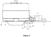
- Figure 3 is a cross-sectional view of the cooking hob according to the first embodiment of the present application;
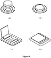
- Figure 4(a) shows an exploded perspective view of a plugging member;
- Figure 4 (b) shows an assembled perspective view of the plugging member shown in Figure 4(a);
- Figure 4(c) shows an exploded perspective view of another plugging member;
- Figure 4(d) shows an assembled perspective view of the plugging member shown in Figure 4(c);
- Figure 5 is a perspective view showing an exploded state of a cooking hob according to a second embodiment of the present application;
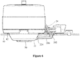
- Figure 6 shows a cross-sectional view of the cooking hob according to the second embodiment of the present application;
- Figure 7 is a perspective view showing an exploded state of a cooking hob according to a third embodiment of the present application;
- Figure 8 is a perspective view of a drip tray of the cooking hob shown in Figure 7; and
- Figure 9 shows a cross-sectional view of the cooking hob according to the third embodiment of the present application.
-
Exemplary embodiments of the present application are described more fully with reference to the accompanying drawings. Same or corresponding structures are represented by corresponding reference numerals, and the repetitive description thereof will be omitted.
-
It is apparent to those skilled in the art that, the exemplary embodiments may be implemented in many different forms without specific details, and hence should not be construed as limiting the scope of the present application. In some exemplary embodiments, the known processes, known device structures, and known techniques will not be described in detail any more.
-
Figure 1 is a perspective view of a cooking hob 1 having a steam system 10 according to a first embodiment of the present application. The cooking hob 1 according to the application relates to a new category of hybrid products by combining steam technology with gas heating, electric heating and/or induction heating techniques. The cooking hob, as an example, includes three cooking areas, wherein a steam cooking zone is arranged in a middle position, while the other two cooking areas are arranged on each side of the steam cooking zone. Specifically, the other two cooking areas may be any one or two of an induction cooking area, an electric cooking area, and/or a gas cooking area.
-
Figure 2 is a perspective view showing an exploded state of the cooking hob 1. As shown, the cooking hob 1 has a cooking panel 40 and includes the steam system 10 and two heating systems embedded in the cooking panel 40, wherein the cooking panel 40 may be, for example, a glass ceramic panel or a metal panel. The cooking panel 40 includes at least one recess 42 and at least one water reservoir 12 arranged into, onto and/or beneath the recess 42. Or optionally, the water reservoir 12 is part of the cooking panel 40. In the illustrated embodiment, the recess 42 is a circular hole (it can also have other shapes) into which the water reservoir 12 is mounted. The water reservoir 12 according to a preferred embodiment includes a flat bottom wall formed as a disk and an inclined side wall encircling the bottom wall, wherein the diameter of the water reservoir 12 is increased from bottom to top. Preferably, the water reservoir 12 is a one-piece component and can be removed from the cooking panel 40, which can facilitate cleaning of the water reservoir 12. For example, the water reservoir 12 can be easily removed and emptied, and then be washed under running water or in a dishwasher at the end of the cooking process.
-
Further, the cooking hob 1 includes at least one heating element (not shown) arranged beneath, beside, and/or inside the water reservoir 12 to boil water in the water reservoir 12 to generate steam. The heating element may be, for example, a tubular heating element and/or an induction heating element.
-
A pad for supporting a steaming container may be arranged over the water reservoir 12. The pad is provided with at least one air hole for the steam to pass upwardly through. When the steaming container is placed on the pad, the at least one air hole on the pad is in communicating with a hole in a bottom of the steaming container, thereby allowing an internal space of the steaming container to communicate with an internal space of the water reservoir 12. In practice, the pad may be a perforated plate, and is not limited to a form of flat plate, for example, the pad may be a drip tray with convex and concave portions. In the embodiments illustrated herein, the pad is exemplarily implemented as a drip tray (such as the drip tray 14 shown in Figure 2) which, in addition to supporting the steaming container, is also used for collecting condensate water and/or food juice dripping from pot holes of the steaming container, and avoiding mixing them with the water in the water reservoir.
-
In the illustrated embodiments, the steam system 10 includes a steaming container implemented as a standard steam cooking pot, and the steam cooking pot includes a pot body 16 and a lid 18. A plurality of pot holes are arranged at a bottom of the pot body 16. However, alternatively the steamed container may also be, for example, a bamboo steamer and a steaming grid. The shape and size of the water reservoir 12 are designed in a manner allowing a stable positioning of dedicated steaming containers, standard steaming containers, and/or commercial steaming containers.
-
The cooking panel 40 is further provided with three switches S for controlling the steam system 10 and two heating systems respectively. In other embodiments than the present, electric, induction, gas burners and steam generator integrated in the cooking hob may be turned on/off and/or regulated by using one or more, same or different switches, such as knobs, physical buttons, and/or touch user interfaces (touch UI).
-
In a case that the water reservoir 12 is filled with water and the heating element (not shown) is activated by a corresponding switch, the water is boiled and steam is generated in the water reservoir 12. Then, the steam escapes upward through the air holes of the drip tray 14, and enters into the steam cooking pot through the pot holes of the pot body 16. Food placed in the steam cooking pot is cooked by the steam.
-
Preferably, the boundary or circumference of the water reservoir 12 is embedded in the cooking panel 40 and is flush with a surface of the cooking panel 40, which is good for the aesthetics of the cooking hob. Preferably, the water reservoir 12 is made of stainless steel. The shape and material of the water reservoir 12 allows for easy cleaning of the water reservoir 12 by a user.
-
In order to facilitate manual refilling of the water reservoir 12, a refill opening for water refilling may be integrally formed on the water reservoir 12. For example, as shown in Figure 2, the water reservoir 12 includes a protrusion 120 extending outward from the circumference, and the refill opening 122 is formed at an end of the protrusion 120. Preferably, the protrusion 120 is embedded in the cooking panel 40 and is flush with the surface of the cooking panel 40. More preferably, the protrusion 120 and the corresponding refill opening 122 are formed at a position away from the other two heating systems. Referring to the cross-sectional view of the cooking hob shown in Figure 3, a water inlet 124 is formed at a suitable position on the side wall of the water reservoir 12, which communicates with the refill opening 122 of a refill area through a pipe 126. Preferably, the water inlet 124 is formed on the side wall of the water reservoir 12 at a position higher than or equal to a maximum allowable water level of the water in the water reservoir 12. By providing such a refill opening 122, the user can fill the water reservoir 12 without touching and/or move any steaming container above the potentially hot water reservoir 12.
-
However, it should be understood that the refill opening may be formed on the water reservoir 12 in other ways. As a possible embodiment, the pipe 126 may be integrally formed on the water reservoir 12, and an end of the pipe extends upwardly such that the end port thereof is exposed to the surface of the cooking panel 40, whereby the end port of the pipe can be directly used as the refill opening.
-
In order to avoid leakage of steam from the refill area, at least one plugging member such as a check valve, cap, plug and/or slide cover may be provided as appropriate at the refill opening 122 and/or the pipe 126 to seal the refill opening and/or the pipe. The at least one plugging member may be mechanically constrained on the steam system 10 or completely independent of the steam system 10, and may be inserted into or removed from the refill area by translational and/or rotational movement. Optionally, the movement of the at least one plugging member may be performed manually or may be performed automatically by using a spring and/or an engine. Furthermore, the opening/closing movement of the at least one plugging member may be performed by the physical button and/or the touch UI. Figures 4(a) to 4(d) show the examples of the plugging members. Figures 4(a) and 4(b) show an open state and a closed state of the plugging member in the form of a plug respectively, and Figures 4(c) and 4(d) show the open state and closed state of the plugging member in the form of a flip respectively. However, it is apparent to those skilled in the art that the plugging member may have many other possible forms.
-
Figures 5 and 6 show another embodiment of the steam system according to the present application. In the present embodiment, the refill area of the steam system 20 is no longer defined by the water reservoir 22, that is, the refill opening 202 is no longer integrally formed on the water reservoir 22, but is instead arranged on the cooking panel 40 beside the water reservoir 22. Preferably, the refill opening 202 is arranged away from other heating systems. With such arrangement, there is no need to provide the water reservoir 22 with an outwardly extending protrusion. In a similar manner, the refill opening 202 is in communication with the water inlet 224 of the water reservoir 22 via the pipe 206 arranged beneath the cooking panel 40. In the light thereof a person skilled in the art, however, will immediately understand that alternatively the connection might be not only realized via a pipe, additionally or alternatively, the connection can be also realized by other connection means, for example through a bended sheet metal. Similarly, in order to avoid leakage of steam from the refill area, at least one plugging member may be provided as appropriate at the refill opening 202 and/or the pipe 206 to close the refill opening 202 and/or the pipe 206, when the water reservoir 22 is not required to be filled. The plugging member may be, for example, one of a check valve, a cap, a plug, and a slide cover.
-
Figure 7 shows yet another embodiment of the steam system according to the present application. In the present embodiment, the cooking panel 40 includes at least one recess 42 and at least one heating surface 31 arranged into, onto and/or beneath the recess 42. Optionally, the at least one heating surface 31 is part of the cooking panel 40. In the illustrated embodiment, the recess 42 is a circular hole into which the heating surface 31 is arranged. In the steam system 30, the water reservoir 32 is in a form of a removable water tray. The water reservoir 32 is not directly heated by the heating element but sits on the heating surface 31. The heating surface 31 is shaped to allow a stable positioning of the removable water reservoir 32. The at least one heating element 50 (see in Figure 9) for generating steam is arranged beneath and/or beside the heating surface 31. Similarly, the at least one heating element 50 may be, for example, a tubular heating element and/or an induction heating element.
-
A drip tray 34 serving as a pad is arranged between the removable water reservoir 32 and the steaming container. However, the water reservoir 32 and the drip tray 34 may also be formed as a one-piece component. Since both the water reservoir 32 and the drip tray 34 can be removed from the cooking panel 40, cleaning of the water reservoir 32 and the drip tray 34 is convenient.
-
Figure 8 shows a perspective view of the drip tray 34. A peripheral wall 340 of the drip tray 34 includes a substantially annular support portion 342 for supporting the steam cooking pot and a circumference 344 extending outwardly and upwardly around the annular support portion 342. A cylindrical projection 360 is formed at a central position of a bottom wall of the drip tray 34, and at least one air hole 362 through which steam passes is formed on a wall, preferable a side wall, portion of the projection 360. In a case that the steaming container is placed on the drip tray 34 and supported by the annular support portion 342, the steam in the water reservoir 32 can enter the steaming container through the at least one air hole 362 and the pot holes at the bottom of the steaming container.
-
Referring to Figure 8, in the present embodiment, in order to refill the removable water reservoir 32, the peripheral wall of the drip tray 34 may be formed with a funnel portion 350. In a case that the steam cooking pot is arranged over the drip tray 34, an mouth 352 of the funnel portion 350 extends radially outside the steam cooking pot and serves as the refill opening, whereby the user can manually fill the water reservoir 32 by a commercial water container (for example, a bottle) and/or a dedicated water container through the mouth 352 of the funnel portion 350 without removing the steam cooking pot. As shown in Figure 8, a radial inward recessed portion 370 is formed at a position of the peripheral wall 340 of the drip tray 34 for forming the funnel portion 350. In a case that the steam cooking pot is arranged over the drip tray 34, a top end of the recessed portion 370 fits along a bottom of the steam cooking pot to prevent the steam entering the drip tray 34 from leaking outward from the top of the recessed portion 370. The funnel portion 350 includes a curved side wall 354 extending downwardly from the top of the recessed portion 370 (or the side wall of the funnel portion is the side wall of the recessed portion or a part of the side wall of the recessed portion), an inclined wall portion 356 extending upwardly and obliquely from the side wall of the funnel portion, and an orifice 358 at a bottom end of the inclined wall portion 356. Preferably, the inclined wall portion 356 extends outwardly beyond the circumference 344 of the drip tray 34 and higher than the circumference 344 as shown in Figure 9, such that when filling water into the funnel portion 350 extending outside the steam cooking pot in an assembled state, water can flow downwardly along the inclined wall portion 356 of the funnel portion through the orifice 358 into the water reservoir 32 at the bottom of the drip tray 34, thereby realizing refilling of the water reservoir 32.
-
Similarly to the foregoing embodiments, in the present embodiment, in order to prevent steam from leaking outside the funnel portion 350 through the orifice 358, at least one plugging member is arranged on the drip tray 34. The plugging member may be, for example, at least one check valve arranged at the orifice 358 and/or the mouth 352 of the funnel portion 350 (such as the plugging member capable of closing the mouth 352 of the funnel portion 350 shown as 330 in Figure 9), or may be a cap, a plug and/or a slide cover arranged at an appropriate position of the funnel portion, to block a passage through which the steam leaks from the water reservoir 32 to the outside of the cooker.
-
In the steam system according to the present application, preferably, at least one electromechanical/electronic sensor (not shown) is further provided to monitor the presence of water, the water level and/or the water temperature. The at least one sensor is, for example, a positive temperature coefficient thermistor sensor (PTC), a negative temperature coefficient thermistor sensor (NTC), a thermostat or a capacitance sensor, etc. Preferably, the at least one sensor includes at least one water level sensor and at least one temperature sensor. The at least one water level sensor may be arranged at a side of or inside the water reservoir. More preferably, the at least one water level sensor includes a maximum water level sensor for detecting a maximum allowable water level of water in the water reservoir and a minimum water level sensor for detecting a minimum allowable water level of water in the water reservoir. The at least one temperature sensor may be arranged beneath, beside, inside and/or over the water reservoir, or arranged beneath, beside, inside and/or over the pipe connecting the refill opening to the water inlet of the water reservoir for monitoring the temperature of the water in the water reservoir.
-
Furthermore, the cooking hob is preferably provided with an alarm (not shown) which cooperates with the sensor. When the sensor detects that the water level or the water temperature is out of a normal range, the alarm sends a visual and/or auditory signal to remind the user. For example, during the steam cooking process, once the water level of the water reservoir is about to be equal to or lower than the minimum allowable water level, the alarm sends a pre-warning signal to remind the user to refill the water reservoir; Once the water level of the water reservoir is about to reach the maximum allowable water level, the alarm sends a pre-warning signal to the user to remind the user to stop refilling; and/or once the water level of the water reservoir is below the minimum allowable water level or above the maximum allowable water level, the alarm sends out an alarm signal. In addition, the alarm can also send out an overheat alarm signal, if the temperature sensor detects that the water temperature is too high. At this time, the user can lower the water temperature by manually refilling water or turning off the heating element.
-
As a more preferable embodiment, the cooking hob is further provided with at least one control element (not shown). The at least one control element can control the turning-on and turning-off of the heating element according to a detection result of the at least one sensor, for example, thereby improving the safety of the cooking hob. For example, the at least one control element can automatically turn off the heating element when the sensor detects that the water temperature is too high or the water level is too high/low. Further preferably, the at least one control element may control the steam cooking process by a duty cycle.
-
By means of the cooking hob according to the embodiment of the present application, since the steam system is integrated on a single cooking panel, steam cooking does not require additional space, thus saving space, which is very advantageous in a kitchen with limited space. Moreover, by combining the steam system together with other cookers such as gas, electric and/or induction burners, a flexible, versatile and cost-effective cooking hob is provided. Moreover, the steam system of the present application can steam a variety of different foods by replacing a suitable steaming container without using another individual small steam system.
-
Furthermore, compared with the existing steam systems, the steam system of the present application on the one hand, simplifies the refilling operation, and on the other hand, ensures a simple structure by providing the refill opening which is convenient for the user to manually refill the water. Furthermore, the water reservoir is easier to empty and clean by making the water reservoir detachable.
-
In addition, the steam system of the present application has higher safety performance. On the one hand, since the refill area is arranged away from burners such as induction, gas burners etc., the user does not risk to get burnt; on the other hand, the user does not have to touch and/or move any steaming containers over the water reservoir which may be hot during the steaming process, thus greatly reducing the risk of getting scalded by the steam or steaming containers; besides, the risk of dry burning, overflow of boiling water and overheating is greatly reduced by providing sensors for detecting water level and temperature.
-
While the illustrative embodiments of present application is described with reference to the drawings, it should be understood that the present application is not limited to any specific embodiments, and those skilled in the art can make other various changes and modifications without departing the scope or the principle of the present application. All such changes and modifications are intent to be included within the scope of the present application defined by the appended claims.