EP3736432A1 - Forming a thrust reverser cascade using corrugated bodies - Google Patents
Forming a thrust reverser cascade using corrugated bodies Download PDFInfo
- Publication number
- EP3736432A1 EP3736432A1 EP19212394.1A EP19212394A EP3736432A1 EP 3736432 A1 EP3736432 A1 EP 3736432A1 EP 19212394 A EP19212394 A EP 19212394A EP 3736432 A1 EP3736432 A1 EP 3736432A1
- Authority
- EP
- European Patent Office
- Prior art keywords
- thrust reverser
- corrugated
- panel
- rail
- manufacturing process
- Prior art date
- Legal status (The legal status is an assumption and is not a legal conclusion. Google has not performed a legal analysis and makes no representation as to the accuracy of the status listed.)
- Granted
Links
Images






Classifications
-
- F—MECHANICAL ENGINEERING; LIGHTING; HEATING; WEAPONS; BLASTING
- F02—COMBUSTION ENGINES; HOT-GAS OR COMBUSTION-PRODUCT ENGINE PLANTS
- F02K—JET-PROPULSION PLANTS
- F02K1/00—Plants characterised by the form or arrangement of the jet pipe or nozzle; Jet pipes or nozzles peculiar thereto
- F02K1/54—Nozzles having means for reversing jet thrust
- F02K1/64—Reversing fan flow
- F02K1/70—Reversing fan flow using thrust reverser flaps or doors mounted on the fan housing
- F02K1/72—Reversing fan flow using thrust reverser flaps or doors mounted on the fan housing the aft end of the fan housing being movable to uncover openings in the fan housing for the reversed flow
-
- B—PERFORMING OPERATIONS; TRANSPORTING
- B29—WORKING OF PLASTICS; WORKING OF SUBSTANCES IN A PLASTIC STATE IN GENERAL
- B29C—SHAPING OR JOINING OF PLASTICS; SHAPING OF MATERIAL IN A PLASTIC STATE, NOT OTHERWISE PROVIDED FOR; AFTER-TREATMENT OF THE SHAPED PRODUCTS, e.g. REPAIRING
- B29C53/00—Shaping by bending, folding, twisting, straightening or flattening; Apparatus therefor
- B29C53/22—Corrugating
- B29C53/24—Corrugating of plates or sheets
-
- B—PERFORMING OPERATIONS; TRANSPORTING
- B29—WORKING OF PLASTICS; WORKING OF SUBSTANCES IN A PLASTIC STATE IN GENERAL
- B29C—SHAPING OR JOINING OF PLASTICS; SHAPING OF MATERIAL IN A PLASTIC STATE, NOT OTHERWISE PROVIDED FOR; AFTER-TREATMENT OF THE SHAPED PRODUCTS, e.g. REPAIRING
- B29C66/00—General aspects of processes or apparatus for joining preformed parts
- B29C66/40—General aspects of joining substantially flat articles, e.g. plates, sheets or web-like materials; Making flat seams in tubular or hollow articles; Joining single elements to substantially flat surfaces
- B29C66/41—Joining substantially flat articles ; Making flat seams in tubular or hollow articles
- B29C66/43—Joining a relatively small portion of the surface of said articles
-
- B—PERFORMING OPERATIONS; TRANSPORTING
- B29—WORKING OF PLASTICS; WORKING OF SUBSTANCES IN A PLASTIC STATE IN GENERAL
- B29C—SHAPING OR JOINING OF PLASTICS; SHAPING OF MATERIAL IN A PLASTIC STATE, NOT OTHERWISE PROVIDED FOR; AFTER-TREATMENT OF THE SHAPED PRODUCTS, e.g. REPAIRING
- B29C66/00—General aspects of processes or apparatus for joining preformed parts
- B29C66/70—General aspects of processes or apparatus for joining preformed parts characterised by the composition, physical properties or the structure of the material of the parts to be joined; Joining with non-plastics material
- B29C66/72—General aspects of processes or apparatus for joining preformed parts characterised by the composition, physical properties or the structure of the material of the parts to be joined; Joining with non-plastics material characterised by the structure of the material of the parts to be joined
- B29C66/721—Fibre-reinforced materials
-
- B—PERFORMING OPERATIONS; TRANSPORTING
- B29—WORKING OF PLASTICS; WORKING OF SUBSTANCES IN A PLASTIC STATE IN GENERAL
- B29C—SHAPING OR JOINING OF PLASTICS; SHAPING OF MATERIAL IN A PLASTIC STATE, NOT OTHERWISE PROVIDED FOR; AFTER-TREATMENT OF THE SHAPED PRODUCTS, e.g. REPAIRING
- B29C70/00—Shaping composites, i.e. plastics material comprising reinforcements, fillers or preformed parts, e.g. inserts
- B29C70/04—Shaping composites, i.e. plastics material comprising reinforcements, fillers or preformed parts, e.g. inserts comprising reinforcements only, e.g. self-reinforcing plastics
- B29C70/28—Shaping operations therefor
- B29C70/40—Shaping or impregnating by compression not applied
- B29C70/42—Shaping or impregnating by compression not applied for producing articles of definite length, i.e. discrete articles
- B29C70/46—Shaping or impregnating by compression not applied for producing articles of definite length, i.e. discrete articles using matched moulds, e.g. for deforming sheet moulding compounds [SMC] or prepregs
-
- F—MECHANICAL ENGINEERING; LIGHTING; HEATING; WEAPONS; BLASTING
- F02—COMBUSTION ENGINES; HOT-GAS OR COMBUSTION-PRODUCT ENGINE PLANTS
- F02K—JET-PROPULSION PLANTS
- F02K1/00—Plants characterised by the form or arrangement of the jet pipe or nozzle; Jet pipes or nozzles peculiar thereto
- F02K1/54—Nozzles having means for reversing jet thrust
-
- B—PERFORMING OPERATIONS; TRANSPORTING
- B29—WORKING OF PLASTICS; WORKING OF SUBSTANCES IN A PLASTIC STATE IN GENERAL
- B29K—INDEXING SCHEME ASSOCIATED WITH SUBCLASSES B29B, B29C OR B29D, RELATING TO MOULDING MATERIALS OR TO MATERIALS FOR MOULDS, REINFORCEMENTS, FILLERS OR PREFORMED PARTS, e.g. INSERTS
- B29K2701/00—Use of unspecified macromolecular compounds for preformed parts, e.g. for inserts
- B29K2701/12—Thermoplastic materials
-
- B—PERFORMING OPERATIONS; TRANSPORTING
- B29—WORKING OF PLASTICS; WORKING OF SUBSTANCES IN A PLASTIC STATE IN GENERAL
- B29L—INDEXING SCHEME ASSOCIATED WITH SUBCLASS B29C, RELATING TO PARTICULAR ARTICLES
- B29L2031/00—Other particular articles
- B29L2031/30—Vehicles, e.g. ships or aircraft, or body parts thereof
- B29L2031/3076—Aircrafts
-
- F—MECHANICAL ENGINEERING; LIGHTING; HEATING; WEAPONS; BLASTING
- F05—INDEXING SCHEMES RELATING TO ENGINES OR PUMPS IN VARIOUS SUBCLASSES OF CLASSES F01-F04
- F05D—INDEXING SCHEME FOR ASPECTS RELATING TO NON-POSITIVE-DISPLACEMENT MACHINES OR ENGINES, GAS-TURBINES OR JET-PROPULSION PLANTS
- F05D2230/00—Manufacture
- F05D2230/20—Manufacture essentially without removing material
- F05D2230/23—Manufacture essentially without removing material by permanently joining parts together
-
- F—MECHANICAL ENGINEERING; LIGHTING; HEATING; WEAPONS; BLASTING
- F05—INDEXING SCHEMES RELATING TO ENGINES OR PUMPS IN VARIOUS SUBCLASSES OF CLASSES F01-F04
- F05D—INDEXING SCHEME FOR ASPECTS RELATING TO NON-POSITIVE-DISPLACEMENT MACHINES OR ENGINES, GAS-TURBINES OR JET-PROPULSION PLANTS
- F05D2230/00—Manufacture
- F05D2230/50—Building or constructing in particular ways
- F05D2230/51—Building or constructing in particular ways in a modular way, e.g. using several identical or complementary parts or features
-
- F—MECHANICAL ENGINEERING; LIGHTING; HEATING; WEAPONS; BLASTING
- F05—INDEXING SCHEMES RELATING TO ENGINES OR PUMPS IN VARIOUS SUBCLASSES OF CLASSES F01-F04
- F05D—INDEXING SCHEME FOR ASPECTS RELATING TO NON-POSITIVE-DISPLACEMENT MACHINES OR ENGINES, GAS-TURBINES OR JET-PROPULSION PLANTS
- F05D2240/00—Components
- F05D2240/10—Stators
- F05D2240/12—Fluid guiding means, e.g. vanes
- F05D2240/129—Cascades, i.e. assemblies of similar profiles acting in parallel
-
- F—MECHANICAL ENGINEERING; LIGHTING; HEATING; WEAPONS; BLASTING
- F05—INDEXING SCHEMES RELATING TO ENGINES OR PUMPS IN VARIOUS SUBCLASSES OF CLASSES F01-F04
- F05D—INDEXING SCHEME FOR ASPECTS RELATING TO NON-POSITIVE-DISPLACEMENT MACHINES OR ENGINES, GAS-TURBINES OR JET-PROPULSION PLANTS
- F05D2300/00—Materials; Properties thereof
- F05D2300/60—Properties or characteristics given to material by treatment or manufacturing
- F05D2300/603—Composites; e.g. fibre-reinforced
-
- Y—GENERAL TAGGING OF NEW TECHNOLOGICAL DEVELOPMENTS; GENERAL TAGGING OF CROSS-SECTIONAL TECHNOLOGIES SPANNING OVER SEVERAL SECTIONS OF THE IPC; TECHNICAL SUBJECTS COVERED BY FORMER USPC CROSS-REFERENCE ART COLLECTIONS [XRACs] AND DIGESTS
- Y02—TECHNOLOGIES OR APPLICATIONS FOR MITIGATION OR ADAPTATION AGAINST CLIMATE CHANGE
- Y02T—CLIMATE CHANGE MITIGATION TECHNOLOGIES RELATED TO TRANSPORTATION
- Y02T50/00—Aeronautics or air transport
- Y02T50/60—Efficient propulsion technologies, e.g. for aircraft
Definitions
- This disclosure relates generally to a thrust reverser for an aircraft propulsion system and, more particularly, to methods for forming a cascade for the thrust reverser.
- An aircraft propulsion system may include a thrust reverser for redirecting bypass air in a forward direction to generate reverse thrust.
- a thrust reverser for redirecting bypass air in a forward direction to generate reverse thrust.
- Many of these thrust reversers include one or more arrays of cascades. Each cascade typically includes a series of aerodynamic vanes for redirecting bypass air in a desired forward direction during reverse thrust operation.
- a composite cascade may be manufactured using a closed-die or autoclave molding process. For example, carbon fiber fabric is laid-up in a mold around mandrels that define open passageways of the cascade. The layup process is generally done by hand and is labor intensive. After this layup, the mold is closed and compressed to consolidate the fabric layers. The process may be expensive, difficult and time consuming.
- a manufacturing process is provided during which a thrust reverser cascade is formed for an aircraft propulsion system.
- a first panel of material is stamped into a first corrugated body.
- a second panel of material is stamped into a second corrugated body.
- the first corrugated body is bonded to the second corrugated body.
- a thrust reverser cascade is formed for an aircraft propulsion system.
- a first panel of material is formed into a first corrugated body with a plurality of first peaks.
- a second panel of material is formed into a second corrugated body with a plurality of second peaks.
- Each of the plurality of first peaks is bonded to a respective one of the plurality of second peaks.
- a thrust reverser cascade is formed for an aircraft propulsion system.
- a plurality of panels are stamped respectively into a plurality of corrugated bodies.
- the plurality of corrugated bodies are arranged side-by-side in an array.
- the arranged plurality of corrugated bodies are respectively bonded together.
- the thrust reverser cascade may be configured from or otherwise include fiber reinforcement within a polymer matrix.
- the first panel of material may be configured from or otherwise include polymer material.
- the first panel of material may be a fiber-reinforced thermoplastic panel of material.
- the bonding of the first corrugated body to the second corrugated body may include bonding a first peak of the first corrugated body to a second peak of the second corrugated body.
- the first peak may be configured with a first chamfered edge.
- the second peak may be configured with a second chamfered edge.
- the second chamfered edge may be bonded to the first chamfered edge.
- the first corrugated body may include a radiused interior corner positioned opposite the first peak.
- the thrust reverser cascade may include a first rail, a second rail and a plurality of vanes connected to and extending between the first rail and the second rail.
- the first corrugated body may be configured as or otherwise include a first corrugation.
- a first section of the first corrugation may form a first of the plurality of vanes.
- a second section of the first corrugation may form a first portion of the first rail.
- the first corrugated body may also include a second corrugation.
- a section of the second corrugation may form a first portion of the second rail.
- the second corrugated body may be configured as or otherwise include a second corrugation.
- a first section of the second corrugation may form a second of the plurality of vanes that is spaced from the first of the plurality of vanes by an air channel.
- a second section of the second corrugation may form a second portion of the first rail that is adjacent and connected to the first portion of the first rail.
- the forming of the thrust reverser cascade may also include bonding a third panel of material to the first corrugated body and the second corrugated body.
- the third panel of material may at least partially form an exterior sidewall of the thrust reverser cascade.
- the first panel of material may be configured with a continuous length of fiber reinforcement that extends end-to-end through the first panel of material.
- the thrust reverser cascade may include a first rail, a second rail and a plurality of vanes connected to and extending between the first rail and the second rail.
- Each of the bonded and arranged plurality of corrugated bodies may form a respective portion of the first rail, a respective portion of the second rail and a respective one of the plurality of vanes.
- the forming of the thrust reverser cascade may also include bonding a flat panel of material to each of the plurality of corrugated bodies.
- the flat panel of material may at least partially form an exterior sidewall of the thrust reverser cascade.
- a first of the plurality of panel may be configured with a continuous length of fiber that extends at least substantially along an entire length of the first of the plurality of panels.
- Each of the plurality of panels may be a fiber-reinforced thermoplastic panel of material.
- the respective bonding of the arranged plurality of corrugated bodies may include bonding a first peak of a first of the plurality of corrugated bodies to a second peak of a second of the plurality of corrugated bodies.
- the present disclosure includes methods for manufacturing one or more cascades for a thrust reverser of an aircraft propulsion system.
- This aircraft propulsion system includes and is powered by a gas turbine engine such as, but not limited to, a turbofan gas turbine engine or a turbojet gas turbine engine.
- a gas turbine engine such as, but not limited to, a turbofan gas turbine engine or a turbojet gas turbine engine.
- An exemplary embodiment of such an aircraft propulsion system 20 and such a thrust reverser 22 is illustrated in FIG. 1 .
- the methods of the present disclosure may be described below with reference to the exemplary aircraft propulsion system 20 and thrust reverser 22 of FIG. 1 .
- the methods of the present disclosure may also be performed to manufacture thrust reverser cascades for different aircraft propulsion systems and cascades of different types and configurations other than those described below and illustrated in the drawings.
- the propulsion system 20 of FIG. 1 includes an outer (e.g., fan / bypass) nacelle structure 24 and an inner (e.g., core) nacelle structure 25 (see FIGS. 2 and 3 ).
- This inner nacelle structure 25 may be referred to as an "inner fixed structure” or an "IFS”.
- the inner nacelle structure 25 houses and is configured to provide an aerodynamic cover for a core of the gas turbine engine.
- the engine core may include a compressor section, a combustion section and a turbine section of the gas turbine engine.
- the outer nacelle structure 24 includes a stationary forward module 26, which may include a nacelle inlet 28 and a fan cowling 30.
- the outer nacelle structure 24 also includes an aft thrust reverser module 32.
- This thrust reverser module 32 includes a translating sleeve 34 and a thrust reverser cascade array 36.
- the thrust reverser module 32 may also include one or more blocker doors 38 configured to deploy and direct air from a bypass flowpath 40 of the aircraft propulsion system 20 into the cascade array 36 during thrust reverser 22 deployment.
- the translating sleeve 34 is configured to translate axially aft along an axial centerline 42 of the propulsion system 20 in order to expose the cascade array 36 and open a thrust reverser flowpath 44 (see FIG. 3 ).
- This thrust reverser flowpath 44 receives bypass air from the bypass flowpath 40, and directs this air through the cascade array 36 which redirects that air in a radially outward and axially forward direction.
- the cascade array 36 may also redirect the air in a circumferential direction in order to, for example, direct the air away from a runway and/or wings of an aircraft as illustrated in FIG. 4 .
- the translating sleeve 34 is also configured to translate axially forward along the centerline 42 in order to cover the cascade array 36 and close the thrust reverser flowpath 44 (see FIG. 2 ).
- the cascade array 36 may include one or more sub-arrays 46.
- the cascade array 36 of FIG. 1 for example, include first and second sub-arrays 46, where the second sub-array 46B is substantially diametrically opposed from the first sub-array 46A and therefore hidden in FIG. 1 .
- Each of these sub-arrays 46 includes one or more thrust reverser cascades 48 arranged circumferentially around the centerline 42.
- FIG. 5 illustrates an exemplary one of the thrust reverser cascades 48.
- This cascade 48 extends longitudinally (e.g., along an x-axis and generally parallel with the centerline 42) between opposing cascade ends 50 and 52.
- the cascade 48 extends laterally (e.g., along a y-axis and generally circumferentially around or tangent to the centerline 42) between opposing cascade sides 54 and 56.
- the cascade 48 also extends transversely (e.g., along a z-axis and generally radially relative to the centerline 42) between opposing inner and outer sides 58 and 60.
- the cascade 48 of FIG. 5 includes a base cascade structure 62 and one or more attachments 64 and 66; e.g., mounting structures. Each of these attachments 64 and 66 is configured to attach / mount the cascade structure 62 to another structure of the propulsion system 20 such as, but not limited to, a torque box 68 or an aft cascade ring 70 (see FIGS. 2 and 3 ).
- the attachments 64 and 66 of FIG. 5 for example, are configured as attachment flanges with apertures for receiving fasteners; e.g., bolds, rivets, etc.
- the cascade structure 62 includes a plurality of strongback rails 72 and one or more arrays 74 of cascade vanes 76.
- the strongback rails 72 of FIG. 5 are arranged parallel with one another, and extend longitudinally between the cascade ends 50 and 52.
- One or more of the strongback rails 72 e.g., the laterally exterior rails
- One or more of the strongback rails 72 may extend into and/or may be configured with one or more of the attachments 64 and 66.
- One or more of the strongback rails 72 (e.g., the laterally interior rails) may extend to one or more of the attachments 64 and 66. Referring to FIG.
- each of the strongback rails 72 may have a non-linear (e.g., curved) cross-sectional geometry in order to redirect air flowing through the cascade 48 in the circumferential direction.
- one or more of the strongback rails 72 may each have a linear (e.g., straight) cross-sectional geometry.
- the arrays 74 of cascade vanes 76 are respectively arranged between laterally adjacent strongback rails 72.
- Each of the arrays 74 of cascade vanes 76 includes a plurality of the cascade vanes 76, which are disposed at discrete locations along the longitudinally length of the strongback rails 72.
- Each longitudinally adjacent pair of vanes 76 thereby forms an air channel 77 therebetween.
- Each of the cascade vanes 76 extends laterally between and is connected to (e.g., bonded to or formed integral with) a respective adjacent set of the strongback rails 72.
- each of the cascade vanes 76 may have a non-linear (e.g., curved) cross-sectional geometry in order to redirect air flowing through the cascade 48 in the axial direction.
- one or more of the cascade vanes 76 may each have a linear (e.g., straight) cross-sectional geometry.
- the entire cascade 48 or at least a portion thereof may be composed of composite material; e.g., fiber-reinforced composite material.
- the cascade 48 may be formed using fiber reinforcement within a polymer matrix; e.g., thermoplastic material.
- the fiber reinforcement material include, but are not limited to, fiberglass material, carbon fiber material, fiberglass, and/or aramid (e.g., Kevlar®) material.
- the fiber material may include one or more continuous lengths of fiber as discussed below in further detail.
- the present disclosure is not limited to the foregoing exemplary materials.
- Each cascade 48 for example, may be formed from any material capable of being processed as described below.
- FIG. 10 is a flow diagram of a process 1000 for forming a thrust reverser cascade. This process 1000 is described below with reference to forming the thrust reverser cascade 48 for ease of description. The process 1000 of FIG. 10 , however, may alternatively be used to form thrust reverser cascades other than the one described above.
- step 1002 the cascade structure 62 is formed.
- This cascade structure 62 may be formed using, for example, a sub-process 1100 as illustrated in FIG. 11 .
- a plurality of panels (e.g., strips) of material 78 are provided, an exemplary one of which is illustrated in FIG. 12 .
- Each of these panels of material 78 may be configured as a fiber-reinforced polymer (e.g., thermoplastic) panel of material.
- each panel of material 78 may include one or more continuous (e.g., uninterrupted) lengths of fiber reinforcement that extend end-to-end through the respective panel of material 78.
- each continuous fiber 80 is embedded with within a polymer (e.g., thermoplastic) matrix 82 and extends at least substantially (e.g., at least 95%) or completely along an entire length 84 of the panel of material 78.
- a single fiber 80 may extend back and forth one or more times at least substantially along the entire length 84 of the panel of material.
- each of the panels of material 78 is formed into a corrugated body 86; e.g., see FIG. 13 .
- each panel of material 78 may be stamped into the corrugated body 86.
- the corrugated body 86 includes one or more corrugations 88 arranged end-to-end along a length thereof.
- Each corrugation 88 includes a first section 90 and a second section 92. A first end of the first section 90 meets and is connected to a first end of the second section 92 at an intra-corrugation peak 94 (e.g., a corner) of the corrugation 88.
- a second end of the first section 90 may meet and be connected to a second end of the second section 92 of an adjacent corrugation 88 at an inter-corrugation peak 96 (e.g., a corner) between the respective corrugations 88.
- the second end of the second section 92 may meet and be connected to the second end of the first section 90 of another adjacent corrugation 88 at another inter-corrugation peak 96 between the respective corrugations 88.
- the corrugated body 86 has a stepped (e.g., zig-zagged) configuration where each of the first sections 90 may form a riser section and each of the second sections 92 may form a run section, or vice versa depending upon the orientation of the corrugated body 86.
- each peak 94 and/or 96 of the corrugated body 86 may have a sharp edge as shown in FIG. 13 .
- at least one or each peak 94 and/or at least one or each peak 96 of the corrugated body 86 may have a chamfered edge as shown in FIG. 14 .
- each intra-corrugation peak 94 is an intra-corrugation interior corner 98 and opposite each inter-corrugation peak 96 is an inter-corrugation interior corner 100.
- Each of these corners 98 and/or 100 of the corrugated body 86 may be configured as a sharp (e.g., a squared-off) corner as shown in FIG. 13 .
- at least one or each corner 98 and/or at least one or each corner 100 of the corrugated body 86 may be configured as a radiused (e.g., curved, arcuate) or filleted corner as shown in FIG. 14 .
- each intra-corrugation peak 94 of each corrugated body 86 is aligned with and may engage (e.g., contact) a respective inter-corrugation peak 96 of an adjacent one of the corrugated bodies 86.
- each inter-corrugation peak 96 of each corrugated body 86 is aligned with and may engage (e.g., contact) a respective intra-corrugation peak 94 of another adjacent one of the corrugated bodies 86.
- the chamfered edges provide additional contact area between the aligned peaks 94 and 96 for subsequent bonding; e.g., see FIG. 16 .
- step 1108 the array of the corrugated bodies 86 are bonded together.
- the aligned peaks 94 and 96 between adjacent corrugated bodies 86 may be welded, adhered and/or otherwise bonded together to provide a corrugated body structure 104.
- At least a portion (or an entirety) of a perimeter of the corrugated body structure 104 is reinforced.
- at least one additional panel of material 106 (similar to or the same as the panels of material 78; see FIG. 12 ) is arranged along the perimeter of the corrugated body structure 104 as shown, for example, in FIG. 17 .
- Each panel of material 106 may extend along an entire side as shown in FIG. 17 .
- a respective panel of material 106 may extend partially along a respective side.
- a respective panel of material 106 may extend along some or all of the sides of the corrugated body structure 104; e.g., wrap partially or completely around the structure 104.
- Each additional panel of material 106 is subsequently bonded to the corrugated body structure 104 to provide the cascade structure 62.
- each first section 90 of each corrugated body 86 may (e.g., completely) form a respective one of the vanes 76, or partially form a respective portion of a respective one of the endwalls 108.
- Each second section 92 of each corrugated body 86 may (e.g., completely) form a respective portion of a respective one of the interior strongback rails 72, or partially form a respective portion of a respective one of the exterior strongback rails 72.
- Each additional panel of material 106 may similarly at least partially form a perimeter wall section (e.g., an exterior sidewall) of the cascade structure 62 such as, for example, a respective exterior strongback rail 72 or a respective endwall 108.
- each vane 76 may be defined by a single first section 90 whereas each strongback rail 72 may be defined by at least a longitudinal array of end-to-end second sections 92.
- one or more of the attachments 64 and 66 are formed; e.g., see FIG. 5 .
- One or more of the attachments 64 and 66 may be formed from a polymer such as thermoplastic material with or without fiber-reinforcement.
- the entire cascade 48 may thereby be formed of the same or similar material; e.g., fiber-reinforce polymer (e.g., thermoplastic) material.
- the attachments 64 and 66 are bonded to the cascade structure 62 to thereby form the cascade 48; e.g., see FIG. 5 .
- Each attachment 64, 66 may be bonded to a respective end 50, 52 of the cascade structure 62 using any suitable bonding technique.
- Such bonding techniques include, but are not limited to, ultrasonic welding, resistance welding, adhesion, etc.
- one or more of the attachments 64 and 66 may be formed along with the cascade structure 62 during the formation step such that the attachment(s) 64, 66 is/are formed integrally with the cascade structure 62.
- the manufacture of the cascade 48 may be at least partially automated and reduce or eliminate requirements for hand layup techniques.
- the panels of material may be cut to length and then stamped using automated equipment.
Landscapes
- Engineering & Computer Science (AREA)
- Mechanical Engineering (AREA)
- Chemical & Material Sciences (AREA)
- Combustion & Propulsion (AREA)
- General Engineering & Computer Science (AREA)
- Composite Materials (AREA)
- Moulding By Coating Moulds (AREA)
Abstract
Description
- This disclosure relates generally to a thrust reverser for an aircraft propulsion system and, more particularly, to methods for forming a cascade for the thrust reverser.
- An aircraft propulsion system may include a thrust reverser for redirecting bypass air in a forward direction to generate reverse thrust. Several types of thrust reversers are known in the art. Many of these thrust reversers include one or more arrays of cascades. Each cascade typically includes a series of aerodynamic vanes for redirecting bypass air in a desired forward direction during reverse thrust operation.
- A composite cascade may be manufactured using a closed-die or autoclave molding process. For example, carbon fiber fabric is laid-up in a mold around mandrels that define open passageways of the cascade. The layup process is generally done by hand and is labor intensive. After this layup, the mold is closed and compressed to consolidate the fabric layers. The process may be expensive, difficult and time consuming.
- There is a need in the art for improved processes for manufacturing a thrust reverser cascade, particularly those made from fiber-reinforced composite material.
- According to an aspect of the present disclosure, a manufacturing process is provided during which a thrust reverser cascade is formed for an aircraft propulsion system. During the formation of the thrust reverser cascade, a first panel of material is stamped into a first corrugated body. A second panel of material is stamped into a second corrugated body. The first corrugated body is bonded to the second corrugated body.
- According to another aspect of the present disclosure, another manufacturing process is provided during which a thrust reverser cascade is formed for an aircraft propulsion system. During the formation of the thrust reverser cascade, a first panel of material is formed into a first corrugated body with a plurality of first peaks. A second panel of material is formed into a second corrugated body with a plurality of second peaks. Each of the plurality of first peaks is bonded to a respective one of the plurality of second peaks.
- According to still another aspect of the present disclosure, another manufacturing process is provided during which a thrust reverser cascade is formed for an aircraft propulsion system. During the formation of the thrust reverser cascade, a plurality of panels are stamped respectively into a plurality of corrugated bodies. The plurality of corrugated bodies are arranged side-by-side in an array. The arranged plurality of corrugated bodies are respectively bonded together.
- In any of the above aspects:
The thrust reverser cascade may be configured from or otherwise include fiber reinforcement within a polymer matrix. - The first panel of material may be configured from or otherwise include polymer material.
- The first panel of material may be a fiber-reinforced thermoplastic panel of material.
- The bonding of the first corrugated body to the second corrugated body may include bonding a first peak of the first corrugated body to a second peak of the second corrugated body.
- The first peak may be configured with a first chamfered edge.
- The second peak may be configured with a second chamfered edge. The second chamfered edge may be bonded to the first chamfered edge.
- The first corrugated body may include a radiused interior corner positioned opposite the first peak.
- The thrust reverser cascade may include a first rail, a second rail and a plurality of vanes connected to and extending between the first rail and the second rail. The first corrugated body may be configured as or otherwise include a first corrugation. A first section of the first corrugation may form a first of the plurality of vanes. A second section of the first corrugation may form a first portion of the first rail.
- The first corrugated body may also include a second corrugation. A section of the second corrugation may form a first portion of the second rail.
- The second corrugated body may be configured as or otherwise include a second corrugation. A first section of the second corrugation may form a second of the plurality of vanes that is spaced from the first of the plurality of vanes by an air channel. A second section of the second corrugation may form a second portion of the first rail that is adjacent and connected to the first portion of the first rail.
- The forming of the thrust reverser cascade may also include bonding a third panel of material to the first corrugated body and the second corrugated body. The third panel of material may at least partially form an exterior sidewall of the thrust reverser cascade.
- The first panel of material may be configured with a continuous length of fiber reinforcement that extends end-to-end through the first panel of material.
- The thrust reverser cascade may include a first rail, a second rail and a plurality of vanes connected to and extending between the first rail and the second rail. Each of the bonded and arranged plurality of corrugated bodies may form a respective portion of the first rail, a respective portion of the second rail and a respective one of the plurality of vanes.
- The forming of the thrust reverser cascade may also include bonding a flat panel of material to each of the plurality of corrugated bodies. The flat panel of material may at least partially form an exterior sidewall of the thrust reverser cascade.
- A first of the plurality of panel may be configured with a continuous length of fiber that extends at least substantially along an entire length of the first of the plurality of panels.
- Each of the plurality of panels may be a fiber-reinforced thermoplastic panel of material.
- The respective bonding of the arranged plurality of corrugated bodies may include bonding a first peak of a first of the plurality of corrugated bodies to a second peak of a second of the plurality of corrugated bodies.
- The foregoing features and the operation of the invention will become more apparent in light of the following description and the accompanying drawings.
-
-
FIG. 1 is a perspective illustration of an aircraft propulsion system with its thrust reverser in a deployed configuration. -
FIG. 2 is a side sectional illustration of an aft portion of the aircraft propulsion system with its thrust reverser in a stowed configuration. -
FIG. 3 is a side sectional illustration of the aft portion of the aircraft propulsion system with its thrust reverser in the deployed configuration. -
FIG. 4 is another perspective illustration of the aircraft propulsion system with its thrust reverser in the deployed configuration as well as exemplary flowpaths of air directed out of the thrust reverser. -
FIG. 5 is a perspective illustration of an embodiment thrust reverser cascade for the thrust reverser. -
FIG. 6 is a cross-sectional illustration of a portion of an embodiment of the thrust reverser cascade. -
FIG. 7 is a cross-sectional illustration of a portion of another embodiment of the thrust reverser cascade. -
FIG. 8 is a side sectional illustration of a portion of an embodiment of the thrust reverser cascade. -
FIG. 9 is a side sectional illustration of a portion of another embodiment of the thrust reverser cascade. -
FIG. 10 is a block diagram of a process for forming a thrust reverser cascade. -
FIG. 11 is a block diagram of a process for forming a cascade structure. -
FIG. 12 is a perspective schematic illustration of a panel of material. -
FIG. 13 is a schematic illustration of a corrugated body. -
FIG. 14 is a schematic illustration of another corrugated body. -
FIG. 15 is a schematic illustration of a corrugated body structure. -
FIG. 16 is a sectional illustration of an exemplary bond joint for the corrugated body structure. -
FIG. 17 is a schematic illustration of the cascade structure. - The present disclosure includes methods for manufacturing one or more cascades for a thrust reverser of an aircraft propulsion system. This aircraft propulsion system includes and is powered by a gas turbine engine such as, but not limited to, a turbofan gas turbine engine or a turbojet gas turbine engine. An exemplary embodiment of such an
aircraft propulsion system 20 and such athrust reverser 22 is illustrated inFIG. 1 . For ease of description, the methods of the present disclosure may be described below with reference to the exemplaryaircraft propulsion system 20 and thrustreverser 22 ofFIG. 1 . The methods of the present disclosure, however, may also be performed to manufacture thrust reverser cascades for different aircraft propulsion systems and cascades of different types and configurations other than those described below and illustrated in the drawings. - The
propulsion system 20 ofFIG. 1 includes an outer (e.g., fan / bypass)nacelle structure 24 and an inner (e.g., core) nacelle structure 25 (seeFIGS. 2 and 3 ). Thisinner nacelle structure 25 may be referred to as an "inner fixed structure" or an "IFS". Referring toFIGS. 2 and 3 , theinner nacelle structure 25 houses and is configured to provide an aerodynamic cover for a core of the gas turbine engine. Briefly, the engine core may include a compressor section, a combustion section and a turbine section of the gas turbine engine. - Referring again to
FIG. 1 , theouter nacelle structure 24 includes astationary forward module 26, which may include anacelle inlet 28 and afan cowling 30. Theouter nacelle structure 24 also includes an aftthrust reverser module 32. Thisthrust reverser module 32 includes a translatingsleeve 34 and a thrustreverser cascade array 36. Referring toFIGS. 2 and 3 , thethrust reverser module 32 may also include one ormore blocker doors 38 configured to deploy and direct air from abypass flowpath 40 of theaircraft propulsion system 20 into thecascade array 36 duringthrust reverser 22 deployment. - The translating
sleeve 34 is configured to translate axially aft along anaxial centerline 42 of thepropulsion system 20 in order to expose thecascade array 36 and open a thrust reverser flowpath 44 (seeFIG. 3 ). Thisthrust reverser flowpath 44 receives bypass air from thebypass flowpath 40, and directs this air through thecascade array 36 which redirects that air in a radially outward and axially forward direction. Thecascade array 36 may also redirect the air in a circumferential direction in order to, for example, direct the air away from a runway and/or wings of an aircraft as illustrated inFIG. 4 . The translatingsleeve 34 is also configured to translate axially forward along thecenterline 42 in order to cover thecascade array 36 and close the thrust reverser flowpath 44 (seeFIG. 2 ). - Referring again to
FIG. 1 , thecascade array 36 may include one or more sub-arrays 46. Thecascade array 36 ofFIG. 1 , for example, include first and second sub-arrays 46, where the second sub-array 46B is substantially diametrically opposed from the first sub-array 46A and therefore hidden inFIG. 1 . Each of these sub-arrays 46 includes one or more thrust reverser cascades 48 arranged circumferentially around thecenterline 42. -
FIG. 5 illustrates an exemplary one of the thrust reverser cascades 48. Thiscascade 48 extends longitudinally (e.g., along an x-axis and generally parallel with the centerline 42) between opposing cascade ends 50 and 52. Thecascade 48 extends laterally (e.g., along a y-axis and generally circumferentially around or tangent to the centerline 42) between opposing cascade sides 54 and 56. Thecascade 48 also extends transversely (e.g., along a z-axis and generally radially relative to the centerline 42) between opposing inner andouter sides - The
cascade 48 ofFIG. 5 includes abase cascade structure 62 and one ormore attachments attachments cascade structure 62 to another structure of thepropulsion system 20 such as, but not limited to, atorque box 68 or an aft cascade ring 70 (seeFIGS. 2 and 3 ). Theattachments FIG. 5 , for example, are configured as attachment flanges with apertures for receiving fasteners; e.g., bolds, rivets, etc. - The
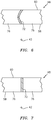
cascade structure 62 includes a plurality of strongback rails 72 and one ormore arrays 74 of cascade vanes 76. The strongback rails 72 ofFIG. 5 are arranged parallel with one another, and extend longitudinally between the cascade ends 50 and 52. One or more of the strongback rails 72 (e.g., the laterally exterior rails) may extend into and/or may be configured with one or more of theattachments attachments FIG. 6 , each of the strongback rails 72 may have a non-linear (e.g., curved) cross-sectional geometry in order to redirect air flowing through thecascade 48 in the circumferential direction. Alternatively, referring toFIG. 7 , one or more of the strongback rails 72 may each have a linear (e.g., straight) cross-sectional geometry. - Referring again to
FIG. 5 , thearrays 74 ofcascade vanes 76 are respectively arranged between laterally adjacent strongback rails 72. Each of thearrays 74 ofcascade vanes 76 includes a plurality of thecascade vanes 76, which are disposed at discrete locations along the longitudinally length of the strongback rails 72. Each longitudinally adjacent pair ofvanes 76 thereby forms anair channel 77 therebetween. Each of the cascade vanes 76 extends laterally between and is connected to (e.g., bonded to or formed integral with) a respective adjacent set of the strongback rails 72. Referring toFIG. 8 , each of thecascade vanes 76 may have a non-linear (e.g., curved) cross-sectional geometry in order to redirect air flowing through thecascade 48 in the axial direction. Alternatively, referring toFIG. 9 , one or more of thecascade vanes 76 may each have a linear (e.g., straight) cross-sectional geometry. - As described below in further detail, the
entire cascade 48 or at least a portion thereof may be composed of composite material; e.g., fiber-reinforced composite material. For example, thecascade 48 may be formed using fiber reinforcement within a polymer matrix; e.g., thermoplastic material. Examples of the fiber reinforcement material include, but are not limited to, fiberglass material, carbon fiber material, fiberglass, and/or aramid (e.g., Kevlar®) material. The fiber material may include one or more continuous lengths of fiber as discussed below in further detail. The present disclosure, however, is not limited to the foregoing exemplary materials. Eachcascade 48, for example, may be formed from any material capable of being processed as described below. -
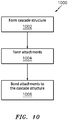
FIG. 10 is a flow diagram of aprocess 1000 for forming a thrust reverser cascade. Thisprocess 1000 is described below with reference to forming thethrust reverser cascade 48 for ease of description. Theprocess 1000 ofFIG. 10 , however, may alternatively be used to form thrust reverser cascades other than the one described above. - In
step 1002, thecascade structure 62 is formed. Thiscascade structure 62 may be formed using, for example, a sub-process 1100 as illustrated inFIG. 11 . - In
step 1102, a plurality of panels (e.g., strips) ofmaterial 78 are provided, an exemplary one of which is illustrated inFIG. 12 . Each of these panels ofmaterial 78 may be configured as a fiber-reinforced polymer (e.g., thermoplastic) panel of material. In some embodiments, each panel ofmaterial 78 may include one or more continuous (e.g., uninterrupted) lengths of fiber reinforcement that extend end-to-end through the respective panel ofmaterial 78. For example, the panel ofmaterial 78 ofFIG. 12 is configured with one or morecontinuous fibers 80, where eachcontinuous fiber 80 is embedded with within a polymer (e.g., thermoplastic)matrix 82 and extends at least substantially (e.g., at least 95%) or completely along anentire length 84 of the panel ofmaterial 78. Of course, in other embodiments, asingle fiber 80 may extend back and forth one or more times at least substantially along theentire length 84 of the panel of material. - In
step 1104, each of the panels ofmaterial 78 is formed into acorrugated body 86; e.g., seeFIG. 13 . For example, each panel ofmaterial 78 may be stamped into thecorrugated body 86. Thecorrugated body 86 includes one ormore corrugations 88 arranged end-to-end along a length thereof. Eachcorrugation 88 includes afirst section 90 and asecond section 92. A first end of thefirst section 90 meets and is connected to a first end of thesecond section 92 at an intra-corrugation peak 94 (e.g., a corner) of thecorrugation 88. A second end of thefirst section 90 may meet and be connected to a second end of thesecond section 92 of anadjacent corrugation 88 at an inter-corrugation peak 96 (e.g., a corner) between therespective corrugations 88. Similarly, the second end of thesecond section 92 may meet and be connected to the second end of thefirst section 90 of anotheradjacent corrugation 88 at anotherinter-corrugation peak 96 between therespective corrugations 88. With such a configuration, thecorrugated body 86 has a stepped (e.g., zig-zagged) configuration where each of thefirst sections 90 may form a riser section and each of thesecond sections 92 may form a run section, or vice versa depending upon the orientation of thecorrugated body 86. - In some embodiments, each peak 94 and/or 96 of the
corrugated body 86 may have a sharp edge as shown inFIG. 13 . However, in other embodiments, at least one or each peak 94 and/or at least one or eachpeak 96 of thecorrugated body 86 may have a chamfered edge as shown inFIG. 14 . - Referring again to
FIG. 13 , opposite eachintra-corrugation peak 94 is an intra-corrugationinterior corner 98 and opposite eachinter-corrugation peak 96 is an inter-corrugationinterior corner 100. Each of thesecorners 98 and/or 100 of thecorrugated body 86 may be configured as a sharp (e.g., a squared-off) corner as shown inFIG. 13 . However, in other embodiments, at least one or eachcorner 98 and/or at least one or eachcorner 100 of thecorrugated body 86 may be configured as a radiused (e.g., curved, arcuate) or filleted corner as shown inFIG. 14 . - In
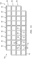
step 1106, thecorrugated bodies 86 are arranged side-by-side in anarray 102 as shown, for example, inFIG. 15 . In thisarray 102, eachintra-corrugation peak 94 of eachcorrugated body 86 is aligned with and may engage (e.g., contact) arespective inter-corrugation peak 96 of an adjacent one of thecorrugated bodies 86. In addition or alternatively, eachinter-corrugation peak 96 of eachcorrugated body 86 is aligned with and may engage (e.g., contact) arespective intra-corrugation peak 94 of another adjacent one of thecorrugated bodies 86. Note, the chamfered edges provide additional contact area between the aligned peaks 94 and 96 for subsequent bonding; e.g., seeFIG. 16 . - In
step 1108, the array of thecorrugated bodies 86 are bonded together. For example, the aligned peaks 94 and 96 between adjacentcorrugated bodies 86 may be welded, adhered and/or otherwise bonded together to provide acorrugated body structure 104. - In
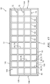
step 1110, at least a portion (or an entirety) of a perimeter of thecorrugated body structure 104 is reinforced. For example, at least one additional panel of material 106 (similar to or the same as the panels ofmaterial 78; seeFIG. 12 ) is arranged along the perimeter of thecorrugated body structure 104 as shown, for example, inFIG. 17 . Each panel ofmaterial 106 may extend along an entire side as shown inFIG. 17 . Alternatively, a respective panel ofmaterial 106 may extend partially along a respective side. Still alternatively, a respective panel ofmaterial 106 may extend along some or all of the sides of thecorrugated body structure 104; e.g., wrap partially or completely around thestructure 104. Each additional panel ofmaterial 106 is subsequently bonded to thecorrugated body structure 104 to provide thecascade structure 62. - With the
formation process 1100 ofFIG. 11 , eachfirst section 90 of eachcorrugated body 86 may (e.g., completely) form a respective one of thevanes 76, or partially form a respective portion of a respective one of theendwalls 108. Eachsecond section 92 of eachcorrugated body 86 may (e.g., completely) form a respective portion of a respective one of the interior strongback rails 72, or partially form a respective portion of a respective one of the exterior strongback rails 72. Each additional panel ofmaterial 106 may similarly at least partially form a perimeter wall section (e.g., an exterior sidewall) of thecascade structure 62 such as, for example, a respectiveexterior strongback rail 72 or arespective endwall 108. Thus, eachvane 76 may be defined by a singlefirst section 90 whereas eachstrongback rail 72 may be defined by at least a longitudinal array of end-to-endsecond sections 92. - Referring again to the
process 1000 ofFIG. 10 , instep 1004, one or more of theattachments FIG. 5 . One or more of theattachments entire cascade 48 may thereby be formed of the same or similar material; e.g., fiber-reinforce polymer (e.g., thermoplastic) material. - In
step 1006, theattachments cascade structure 62 to thereby form thecascade 48; e.g., seeFIG. 5 . Eachattachment respective end cascade structure 62 using any suitable bonding technique. Such bonding techniques include, but are not limited to, ultrasonic welding, resistance welding, adhesion, etc. Of course, in other embodiments, one or more of theattachments cascade structure 62 during the formation step such that the attachment(s) 64, 66 is/are formed integrally with thecascade structure 62. - Using the processes of
FIGS. 10 and11 , the manufacture of thecascade 48 may be at least partially automated and reduce or eliminate requirements for hand layup techniques. For example, the panels of material may be cut to length and then stamped using automated equipment. - While various embodiments of the present invention have been disclosed, it will be apparent to those of ordinary skill in the art that many more embodiments and implementations are possible within the scope of the invention. For example, the present invention as described herein includes several aspects and embodiments that include particular features. Although these features may be described individually, it is within the scope of the present invention that some or all of these features may be combined with any one of the aspects and remain within the scope of the invention. Accordingly, the present invention is not to be restricted except in light of the attached claims and their equivalents.
Claims (15)
- A manufacturing process, comprising:
forming a thrust reverser cascade for an aircraft propulsion system, the forming of the thrust reverser cascade comprisingstamping a first panel of material into a first corrugated body;stamping a second panel of material into a second corrugated body; andbonding the first corrugated body to the second corrugated body. - The manufacturing process of claim 1, wherein the first panel of material comprises polymer material.
- The manufacturing process of claim 1 or 2, wherein the first panel of material is a fiber-reinforced thermoplastic panel of material.
- The manufacturing process of any preceding claim, wherein the bonding of the first corrugated body to the second corrugated body comprises bonding a first peak of the first corrugated body to a second peak of the second corrugated body,
wherein the first peak is optionally configured with a first chamfered edge, wherein, optionally,
the second peak is configured with a second chamfered edge; and
the second chamfered edge is bonded to the first chamfered edge. - The manufacturing process of claim 4, wherein the first corrugated body includes a radiused interior corner positioned opposite the first peak.
- The manufacturing process of any preceding claim, wherein
the thrust reverser cascade includes a first rail, a second rail and a plurality of vanes connected to and extending between the first rail and the second rail;
the first corrugated body comprises a first corrugation;
a first section of the first corrugation forms a first of the plurality of vanes; and
a second section of the first corrugation forms a first portion of the first rail. - The manufacturing process of claim 6, wherein
the first corrugated body further comprises a second corrugation; and
a section of the second corrugation forms a first portion of the second rail. - The manufacturing process of claim 6 or 7, wherein
the second corrugated body comprises a second corrugation;
a first section of the second corrugation forms a second of the plurality of vanes that is spaced from the first of the plurality of vanes by an air channel; and
a second section of the second corrugation forms a second portion of the first rail that is adjacent and connected to the first portion of the first rail. - The manufacturing process of any preceding claim, wherein
the forming of the thrust reverser cascade further comprises bonding a third panel of material to the first corrugated body and the second corrugated body; and
the third panel of material at least partially forms an exterior sidewall of the thrust reverser cascade. - The manufacturing process of any preceding claim, wherein the first panel of material is configured with a continuous length of fiber reinforcement that extends end-to-end through the first panel of material.
- A manufacturing process, comprising:forming a thrust reverser cascade for an aircraft propulsion system, the forming of the thrust reverser cascade comprisingforming a first panel of material into a first corrugated body with a plurality of first peaks;forming a second panel of material into a second corrugated body with a plurality of second peaks; andbonding each of the plurality of first peaks to a respective one of the plurality of second peaks,wherein the thrust reverser cascade optionally comprises fiber reinforcement within a polymer matrix.
- A manufacturing process, comprising:forming a thrust reverser cascade for an aircraft propulsion system, the forming of the thrust reverser cascade comprisingstamping a plurality of panels respectively into a plurality of corrugated bodies, wherein each of the plurality of panels is optionally a fiber-reinforced thermoplastic panel of material;
arranging the plurality of corrugated bodies side-by-side in an array; and respectively bonding the arranged plurality of corrugated bodies together. - The manufacturing process of claim 12, wherein
the thrust reverser cascade includes a first rail, a second rail and a plurality of vanes connected to and extending between the first rail and the second rail; and
each of the bonded and arranged plurality of corrugated bodies forms a respective portion of the first rail, a respective portion of the second rail and a respective one of the plurality of vanes. - The manufacturing process of claim 12 or 13, wherein
the forming of the thrust reverser cascade further comprises bonding a flat panel of material to each of the plurality of corrugated bodies; and
the flat panel of material at least partially forms an exterior sidewall of the thrust reverser cascade. - The manufacturing process of claims 12 to 14, wherein:a first of the plurality of panels is configured with a continuous length of fiber that extends at least substantially along an entire length of the first of the plurality of panels; and/orthe respective bonding of the arranged plurality of corrugated bodies comprises bonding a first peak of a first of the plurality of corrugated bodies to a second peak of a second of the plurality of corrugated bodies.
Applications Claiming Priority (1)
| Application Number | Priority Date | Filing Date | Title |
|---|---|---|---|
| US16/404,363 US11123916B2 (en) | 2019-05-06 | 2019-05-06 | Forming a thrust reverser cascade using corrugated bodies |
Publications (2)
| Publication Number | Publication Date |
|---|---|
| EP3736432A1 true EP3736432A1 (en) | 2020-11-11 |
| EP3736432B1 EP3736432B1 (en) | 2023-03-08 |
Family
ID=68732828
Family Applications (1)
| Application Number | Title | Priority Date | Filing Date |
|---|---|---|---|
| EP19212394.1A Active EP3736432B1 (en) | 2019-05-06 | 2019-11-29 | Forming a thrust reverser cascade using corrugated bodies |
Country Status (2)
| Country | Link |
|---|---|
| US (2) | US11123916B2 (en) |
| EP (1) | EP3736432B1 (en) |
Families Citing this family (4)
| Publication number | Priority date | Publication date | Assignee | Title |
|---|---|---|---|---|
| US12014712B2 (en) | 2021-09-02 | 2024-06-18 | Rohr, Inc. | Corrugated acoustic stiffening devices and methods |
| US11993388B2 (en) | 2021-09-02 | 2024-05-28 | Rohr, Inc. | Corrugated stiffening devices utilizing peaks and valleys and methods of manufacture |
| US11780179B2 (en) | 2021-09-02 | 2023-10-10 | Rohr, Inc. | Thermoplastic composite panel with corrugated peaks and troughs stiffening systems and methods |
| US12043385B2 (en) | 2021-09-13 | 2024-07-23 | Rohr, Inc. | Aircraft control surface having variable height corrugated core |
Citations (3)
| Publication number | Priority date | Publication date | Assignee | Title |
|---|---|---|---|---|
| US20160263820A1 (en) * | 2015-03-13 | 2016-09-15 | Rohr, Inc. | Method of manufacturing thrust reverser cascades |
| FR3048025A1 (en) * | 2016-02-19 | 2017-08-25 | Safran | METHOD FOR MANUFACTURING A TURBOMACHINE PUSH INVERTER GRID |
| US20190113001A1 (en) * | 2017-10-18 | 2019-04-18 | Spirit Aerosystems, Inc. | Cascade segment for thrust reverser with repeating modular units, and method of manufacturing same |
Family Cites Families (29)
| Publication number | Priority date | Publication date | Assignee | Title |
|---|---|---|---|---|
| US3356555A (en) * | 1964-10-29 | 1967-12-05 | Hexcel Corp | Method and apparatus for the manufacture of honeycomb product |
| US4067094A (en) | 1976-04-26 | 1978-01-10 | Harry Feick Co., Inc. | Load bearing vane structure for thrust reversal |
| US4852805A (en) | 1983-12-30 | 1989-08-01 | The Boeing Company | Hybrid thrust reverser cascade basket and method |
| US4722821A (en) | 1983-12-30 | 1988-02-02 | The Boeing Company | Method of making a cascade basket for a thrust reverser |
| US4596621A (en) | 1984-01-03 | 1986-06-24 | The Boeing Company | Method of making a composite bond cascade for a thrust reverser unit of an aircraft engine nacelle |
| US5330599A (en) | 1988-12-19 | 1994-07-19 | Lockheed Missiles & Space Company, Inc. | Grid structures |
| US4893743A (en) * | 1989-05-09 | 1990-01-16 | The United States Of America As Represented By The Secretary Of The Air Force | Method to produce superplastically formed titanium aluminide components |
| US5399221A (en) * | 1990-05-04 | 1995-03-21 | Northrop Grumman Corporation | Continuous process for forming fiber-reinforced high temperature thermoplastic resin honeycomb structures |
| EP0590032B1 (en) | 1991-05-24 | 1999-04-28 | Dow-United Technologies Composite Products, Inc. | Braided complex composite parts and methods of forming same |
| US6725541B1 (en) | 2000-01-21 | 2004-04-27 | Rolls-Royce Plc | Flow directing element and a method of manufacturing a flow directing element |
| GB0001279D0 (en) | 2000-01-21 | 2000-03-08 | Rolls Royce Plc | A flow directing element and a method of manufacturing a flow directing element |
| US6579404B2 (en) * | 2001-01-23 | 2003-06-17 | Northrop Grumman Corporation | Method of making precision geometry advanced composite honeycomb material for spacecraft applications and honeycomb material made thereby |
| FR2869258B1 (en) | 2004-04-27 | 2006-07-21 | Hurel Hispano Sa | METHOD FOR MANUFACTURING ELEMENTS, SUCH AS FLANGES FOR CASCADES OF PUSHED INVERTER, BY MOLDING COMPOSITE MATERIAL |
| WO2007149535A1 (en) * | 2006-06-21 | 2007-12-27 | Ben Strauss | Honeycomb with a fraction of substantially porous cell walls |
| US20080182017A1 (en) | 2007-01-31 | 2008-07-31 | General Electric Company | Laser net shape manufacturing and repair using a medial axis toolpath deposition method |
| DE102008021684A1 (en) | 2008-04-30 | 2009-11-05 | Rolls-Royce Deutschland Ltd & Co Kg | Guide vanes of a vane grille of an aircraft gas turbine |
| US9045992B2 (en) | 2010-06-28 | 2015-06-02 | Herakles | Turbomachine blades or vanes having complementary even/odd geometry |
| US8484944B2 (en) | 2010-08-13 | 2013-07-16 | Spirit Aerosystems, Inc. | Aerodynamic device for thrust reverser cascades |
| US8642151B2 (en) | 2011-01-21 | 2014-02-04 | Albany Engineered Composites, Inc. | Preform and method for reinforcing woven fiber nodes |
| US9086034B2 (en) * | 2011-10-13 | 2015-07-21 | Rohr, Inc. | Thrust reverser cascade assembly with flow deflection shelf |
| US20140099476A1 (en) | 2012-10-08 | 2014-04-10 | Ramesh Subramanian | Additive manufacture of turbine component with multiple materials |
| US9694544B2 (en) | 2013-03-22 | 2017-07-04 | Markforged, Inc. | Methods for fiber reinforced additive manufacturing |
| US20140328688A1 (en) | 2013-05-03 | 2014-11-06 | General Electric Company | Rotor blade assembly having vortex generators for wind turbine |
| JP6475232B2 (en) | 2013-06-05 | 2019-02-27 | マークフォージド,インコーポレーテッド | Fiber reinforced additive manufacturing method |
| WO2015006445A1 (en) | 2013-07-09 | 2015-01-15 | United Technologies Corporation | Plated polymer nacelle |
| US9835112B2 (en) | 2014-02-10 | 2017-12-05 | MRA Systems Inc. | Thrust reverser cascade |
| US9895840B2 (en) | 2014-05-15 | 2018-02-20 | The Boeing Company | Thermoformed cascades for jet engine thrust reversers |
| US10823112B2 (en) | 2017-05-25 | 2020-11-03 | The Boeing Company | Method for manufacturing and assembly of a thrust reverser cascade |
| US10598127B2 (en) | 2017-08-15 | 2020-03-24 | Spirit Aerosystems, Inc. | Method of fabricating a thrust reverser cascade assembly |
-
2019
- 2019-05-06 US US16/404,363 patent/US11123916B2/en active Active
- 2019-11-29 EP EP19212394.1A patent/EP3736432B1/en active Active
-
2021
- 2021-09-20 US US17/479,384 patent/US11668265B2/en active Active
Patent Citations (3)
| Publication number | Priority date | Publication date | Assignee | Title |
|---|---|---|---|---|
| US20160263820A1 (en) * | 2015-03-13 | 2016-09-15 | Rohr, Inc. | Method of manufacturing thrust reverser cascades |
| FR3048025A1 (en) * | 2016-02-19 | 2017-08-25 | Safran | METHOD FOR MANUFACTURING A TURBOMACHINE PUSH INVERTER GRID |
| US20190113001A1 (en) * | 2017-10-18 | 2019-04-18 | Spirit Aerosystems, Inc. | Cascade segment for thrust reverser with repeating modular units, and method of manufacturing same |
Also Published As
| Publication number | Publication date |
|---|---|
| US20220176614A1 (en) | 2022-06-09 |
| US11668265B2 (en) | 2023-06-06 |
| US20200353667A1 (en) | 2020-11-12 |
| EP3736432B1 (en) | 2023-03-08 |
| US11123916B2 (en) | 2021-09-21 |
Similar Documents
| Publication | Publication Date | Title |
|---|---|---|
| US11668265B2 (en) | Forming a thrust reverser cascade using corrugated bodies | |
| EP3141375B1 (en) | Additive manufacturing a fiber-reinforced thrust reverser cascade assembly | |
| US8127530B2 (en) | Thrust reverser for a turbofan gas turbine engine | |
| EP3527812B1 (en) | Thrust reverser cascade | |
| EP3594127B1 (en) | Active laminar flow control system with composite panel | |
| EP3871979B1 (en) | Structural panel with integrated coupler | |
| US10738738B2 (en) | Nacelle with bifurcation extension and integral structural reinforcement | |
| US12286905B2 (en) | Rotor assembly for gas turbine engines | |
| EP4223980A2 (en) | Rotor assembly with structural platforms for gas turbine engines | |
| EP3599370B1 (en) | Low cost joined cascade | |
| US11391167B2 (en) | Hybrid airfoil for gas turbine engines | |
| EP4397850A1 (en) | Manufacturing thrust reverser blocker door using overmolding | |
| EP3578790B1 (en) | Cascade assembly for a jet engine thrust reverser | |
| EP3599369B1 (en) | Cascade array vanes with assembly features | |
| US12194700B2 (en) | Forming duct structure with overbraided woven fiber sleeve | |
| US12397512B2 (en) | Forming duct structure with overbraided woven fiber sleeve | |
| US20240151147A1 (en) | Airfoil and methods of assembly thereof | |
| US20250290451A1 (en) | Gas turbine engine |
Legal Events
| Date | Code | Title | Description |
|---|---|---|---|
| PUAI | Public reference made under article 153(3) epc to a published international application that has entered the european phase |
Free format text: ORIGINAL CODE: 0009012 |
|
| STAA | Information on the status of an ep patent application or granted ep patent |
Free format text: STATUS: THE APPLICATION HAS BEEN PUBLISHED |
|
| AK | Designated contracting states |
Kind code of ref document: A1 Designated state(s): AL AT BE BG CH CY CZ DE DK EE ES FI FR GB GR HR HU IE IS IT LI LT LU LV MC MK MT NL NO PL PT RO RS SE SI SK SM TR |
|
| STAA | Information on the status of an ep patent application or granted ep patent |
Free format text: STATUS: REQUEST FOR EXAMINATION WAS MADE |
|
| 17P | Request for examination filed |
Effective date: 20210511 |
|
| RBV | Designated contracting states (corrected) |
Designated state(s): AL AT BE BG CH CY CZ DE DK EE ES FI FR GB GR HR HU IE IS IT LI LT LU LV MC MK MT NL NO PL PT RO RS SE SI SK SM TR |
|
| GRAP | Despatch of communication of intention to grant a patent |
Free format text: ORIGINAL CODE: EPIDOSNIGR1 |
|
| STAA | Information on the status of an ep patent application or granted ep patent |
Free format text: STATUS: GRANT OF PATENT IS INTENDED |
|
| INTG | Intention to grant announced |
Effective date: 20220922 |
|
| GRAS | Grant fee paid |
Free format text: ORIGINAL CODE: EPIDOSNIGR3 |
|
| GRAA | (expected) grant |
Free format text: ORIGINAL CODE: 0009210 |
|
| STAA | Information on the status of an ep patent application or granted ep patent |
Free format text: STATUS: THE PATENT HAS BEEN GRANTED |
|
| AK | Designated contracting states |
Kind code of ref document: B1 Designated state(s): AL AT BE BG CH CY CZ DE DK EE ES FI FR GB GR HR HU IE IS IT LI LT LU LV MC MK MT NL NO PL PT RO RS SE SI SK SM TR |
|
| REG | Reference to a national code |
Ref country code: CH Ref legal event code: EP Ref country code: AT Ref legal event code: REF Ref document number: 1552715 Country of ref document: AT Kind code of ref document: T Effective date: 20230315 |
|
| REG | Reference to a national code |
Ref country code: DE Ref legal event code: R096 Ref document number: 602019026104 Country of ref document: DE |
|
| REG | Reference to a national code |
Ref country code: IE Ref legal event code: FG4D |
|
| REG | Reference to a national code |
Ref country code: LT Ref legal event code: MG9D |
|
| REG | Reference to a national code |
Ref country code: NL Ref legal event code: MP Effective date: 20230308 |
|
| PG25 | Lapsed in a contracting state [announced via postgrant information from national office to epo] |
Ref country code: RS Free format text: LAPSE BECAUSE OF FAILURE TO SUBMIT A TRANSLATION OF THE DESCRIPTION OR TO PAY THE FEE WITHIN THE PRESCRIBED TIME-LIMIT Effective date: 20230308 Ref country code: NO Free format text: LAPSE BECAUSE OF FAILURE TO SUBMIT A TRANSLATION OF THE DESCRIPTION OR TO PAY THE FEE WITHIN THE PRESCRIBED TIME-LIMIT Effective date: 20230608 Ref country code: LV Free format text: LAPSE BECAUSE OF FAILURE TO SUBMIT A TRANSLATION OF THE DESCRIPTION OR TO PAY THE FEE WITHIN THE PRESCRIBED TIME-LIMIT Effective date: 20230308 Ref country code: LT Free format text: LAPSE BECAUSE OF FAILURE TO SUBMIT A TRANSLATION OF THE DESCRIPTION OR TO PAY THE FEE WITHIN THE PRESCRIBED TIME-LIMIT Effective date: 20230308 Ref country code: HR Free format text: LAPSE BECAUSE OF FAILURE TO SUBMIT A TRANSLATION OF THE DESCRIPTION OR TO PAY THE FEE WITHIN THE PRESCRIBED TIME-LIMIT Effective date: 20230308 Ref country code: ES Free format text: LAPSE BECAUSE OF FAILURE TO SUBMIT A TRANSLATION OF THE DESCRIPTION OR TO PAY THE FEE WITHIN THE PRESCRIBED TIME-LIMIT Effective date: 20230308 |
|
| REG | Reference to a national code |
Ref country code: AT Ref legal event code: MK05 Ref document number: 1552715 Country of ref document: AT Kind code of ref document: T Effective date: 20230308 |
|
| PG25 | Lapsed in a contracting state [announced via postgrant information from national office to epo] |
Ref country code: SE Free format text: LAPSE BECAUSE OF FAILURE TO SUBMIT A TRANSLATION OF THE DESCRIPTION OR TO PAY THE FEE WITHIN THE PRESCRIBED TIME-LIMIT Effective date: 20230308 Ref country code: NL Free format text: LAPSE BECAUSE OF FAILURE TO SUBMIT A TRANSLATION OF THE DESCRIPTION OR TO PAY THE FEE WITHIN THE PRESCRIBED TIME-LIMIT Effective date: 20230308 Ref country code: GR Free format text: LAPSE BECAUSE OF FAILURE TO SUBMIT A TRANSLATION OF THE DESCRIPTION OR TO PAY THE FEE WITHIN THE PRESCRIBED TIME-LIMIT Effective date: 20230609 Ref country code: FI Free format text: LAPSE BECAUSE OF FAILURE TO SUBMIT A TRANSLATION OF THE DESCRIPTION OR TO PAY THE FEE WITHIN THE PRESCRIBED TIME-LIMIT Effective date: 20230308 |
|
| PG25 | Lapsed in a contracting state [announced via postgrant information from national office to epo] |
Ref country code: SM Free format text: LAPSE BECAUSE OF FAILURE TO SUBMIT A TRANSLATION OF THE DESCRIPTION OR TO PAY THE FEE WITHIN THE PRESCRIBED TIME-LIMIT Effective date: 20230308 Ref country code: RO Free format text: LAPSE BECAUSE OF FAILURE TO SUBMIT A TRANSLATION OF THE DESCRIPTION OR TO PAY THE FEE WITHIN THE PRESCRIBED TIME-LIMIT Effective date: 20230308 Ref country code: PT Free format text: LAPSE BECAUSE OF FAILURE TO SUBMIT A TRANSLATION OF THE DESCRIPTION OR TO PAY THE FEE WITHIN THE PRESCRIBED TIME-LIMIT Effective date: 20230710 Ref country code: EE Free format text: LAPSE BECAUSE OF FAILURE TO SUBMIT A TRANSLATION OF THE DESCRIPTION OR TO PAY THE FEE WITHIN THE PRESCRIBED TIME-LIMIT Effective date: 20230308 Ref country code: CZ Free format text: LAPSE BECAUSE OF FAILURE TO SUBMIT A TRANSLATION OF THE DESCRIPTION OR TO PAY THE FEE WITHIN THE PRESCRIBED TIME-LIMIT Effective date: 20230308 Ref country code: AT Free format text: LAPSE BECAUSE OF FAILURE TO SUBMIT A TRANSLATION OF THE DESCRIPTION OR TO PAY THE FEE WITHIN THE PRESCRIBED TIME-LIMIT Effective date: 20230308 |
|
| PG25 | Lapsed in a contracting state [announced via postgrant information from national office to epo] |
Ref country code: SK Free format text: LAPSE BECAUSE OF FAILURE TO SUBMIT A TRANSLATION OF THE DESCRIPTION OR TO PAY THE FEE WITHIN THE PRESCRIBED TIME-LIMIT Effective date: 20230308 Ref country code: PL Free format text: LAPSE BECAUSE OF FAILURE TO SUBMIT A TRANSLATION OF THE DESCRIPTION OR TO PAY THE FEE WITHIN THE PRESCRIBED TIME-LIMIT Effective date: 20230308 Ref country code: IS Free format text: LAPSE BECAUSE OF FAILURE TO SUBMIT A TRANSLATION OF THE DESCRIPTION OR TO PAY THE FEE WITHIN THE PRESCRIBED TIME-LIMIT Effective date: 20230708 |
|
| REG | Reference to a national code |
Ref country code: DE Ref legal event code: R097 Ref document number: 602019026104 Country of ref document: DE |
|
| PLBE | No opposition filed within time limit |
Free format text: ORIGINAL CODE: 0009261 |
|
| STAA | Information on the status of an ep patent application or granted ep patent |
Free format text: STATUS: NO OPPOSITION FILED WITHIN TIME LIMIT |
|
| PG25 | Lapsed in a contracting state [announced via postgrant information from national office to epo] |
Ref country code: SI Free format text: LAPSE BECAUSE OF FAILURE TO SUBMIT A TRANSLATION OF THE DESCRIPTION OR TO PAY THE FEE WITHIN THE PRESCRIBED TIME-LIMIT Effective date: 20230308 Ref country code: DK Free format text: LAPSE BECAUSE OF FAILURE TO SUBMIT A TRANSLATION OF THE DESCRIPTION OR TO PAY THE FEE WITHIN THE PRESCRIBED TIME-LIMIT Effective date: 20230308 |
|
| 26N | No opposition filed |
Effective date: 20231211 |
|
| PG25 | Lapsed in a contracting state [announced via postgrant information from national office to epo] |
Ref country code: IT Free format text: LAPSE BECAUSE OF FAILURE TO SUBMIT A TRANSLATION OF THE DESCRIPTION OR TO PAY THE FEE WITHIN THE PRESCRIBED TIME-LIMIT Effective date: 20230308 |
|
| REG | Reference to a national code |
Ref country code: CH Ref legal event code: PL |
|
| PG25 | Lapsed in a contracting state [announced via postgrant information from national office to epo] |
Ref country code: MC Free format text: LAPSE BECAUSE OF FAILURE TO SUBMIT A TRANSLATION OF THE DESCRIPTION OR TO PAY THE FEE WITHIN THE PRESCRIBED TIME-LIMIT Effective date: 20230308 |
|
| PG25 | Lapsed in a contracting state [announced via postgrant information from national office to epo] |
Ref country code: LU Free format text: LAPSE BECAUSE OF NON-PAYMENT OF DUE FEES Effective date: 20231129 |
|
| PG25 | Lapsed in a contracting state [announced via postgrant information from national office to epo] |
Ref country code: CH Free format text: LAPSE BECAUSE OF NON-PAYMENT OF DUE FEES Effective date: 20231130 |
|
| PG25 | Lapsed in a contracting state [announced via postgrant information from national office to epo] |
Ref country code: MC Free format text: LAPSE BECAUSE OF FAILURE TO SUBMIT A TRANSLATION OF THE DESCRIPTION OR TO PAY THE FEE WITHIN THE PRESCRIBED TIME-LIMIT Effective date: 20230308 Ref country code: LU Free format text: LAPSE BECAUSE OF NON-PAYMENT OF DUE FEES Effective date: 20231129 Ref country code: CH Free format text: LAPSE BECAUSE OF NON-PAYMENT OF DUE FEES Effective date: 20231130 |
|
| REG | Reference to a national code |
Ref country code: BE Ref legal event code: MM Effective date: 20231130 |
|
| REG | Reference to a national code |
Ref country code: IE Ref legal event code: MM4A |
|
| PG25 | Lapsed in a contracting state [announced via postgrant information from national office to epo] |
Ref country code: IE Free format text: LAPSE BECAUSE OF NON-PAYMENT OF DUE FEES Effective date: 20231129 |
|
| PG25 | Lapsed in a contracting state [announced via postgrant information from national office to epo] |
Ref country code: BE Free format text: LAPSE BECAUSE OF NON-PAYMENT OF DUE FEES Effective date: 20231130 |
|
| PG25 | Lapsed in a contracting state [announced via postgrant information from national office to epo] |
Ref country code: IE Free format text: LAPSE BECAUSE OF NON-PAYMENT OF DUE FEES Effective date: 20231129 Ref country code: BE Free format text: LAPSE BECAUSE OF NON-PAYMENT OF DUE FEES Effective date: 20231130 |
|
| PG25 | Lapsed in a contracting state [announced via postgrant information from national office to epo] |
Ref country code: BG Free format text: LAPSE BECAUSE OF FAILURE TO SUBMIT A TRANSLATION OF THE DESCRIPTION OR TO PAY THE FEE WITHIN THE PRESCRIBED TIME-LIMIT Effective date: 20230308 |
|
| PG25 | Lapsed in a contracting state [announced via postgrant information from national office to epo] |
Ref country code: BG Free format text: LAPSE BECAUSE OF FAILURE TO SUBMIT A TRANSLATION OF THE DESCRIPTION OR TO PAY THE FEE WITHIN THE PRESCRIBED TIME-LIMIT Effective date: 20230308 |
|
| PG25 | Lapsed in a contracting state [announced via postgrant information from national office to epo] |
Ref country code: CY Free format text: LAPSE BECAUSE OF FAILURE TO SUBMIT A TRANSLATION OF THE DESCRIPTION OR TO PAY THE FEE WITHIN THE PRESCRIBED TIME-LIMIT; INVALID AB INITIO Effective date: 20191129 |
|
| PG25 | Lapsed in a contracting state [announced via postgrant information from national office to epo] |
Ref country code: HU Free format text: LAPSE BECAUSE OF FAILURE TO SUBMIT A TRANSLATION OF THE DESCRIPTION OR TO PAY THE FEE WITHIN THE PRESCRIBED TIME-LIMIT; INVALID AB INITIO Effective date: 20191129 |
|
| PG25 | Lapsed in a contracting state [announced via postgrant information from national office to epo] |
Ref country code: TR Free format text: LAPSE BECAUSE OF FAILURE TO SUBMIT A TRANSLATION OF THE DESCRIPTION OR TO PAY THE FEE WITHIN THE PRESCRIBED TIME-LIMIT Effective date: 20230308 |
|
| PGFP | Annual fee paid to national office [announced via postgrant information from national office to epo] |
Ref country code: DE Payment date: 20251022 Year of fee payment: 7 |
|
| PGFP | Annual fee paid to national office [announced via postgrant information from national office to epo] |
Ref country code: GB Payment date: 20251023 Year of fee payment: 7 |
|
| PGFP | Annual fee paid to national office [announced via postgrant information from national office to epo] |
Ref country code: FR Payment date: 20251022 Year of fee payment: 7 |
|
| P01 | Opt-out of the competence of the unified patent court (upc) registered |
Free format text: CASE NUMBER: UPC_APP_0019027_3736432/2025 Effective date: 20251222 |