EP3736427B1 - Power modules for hypersonic vehicles - Google Patents
Power modules for hypersonic vehicles Download PDFInfo
- Publication number
- EP3736427B1 EP3736427B1 EP19212195.2A EP19212195A EP3736427B1 EP 3736427 B1 EP3736427 B1 EP 3736427B1 EP 19212195 A EP19212195 A EP 19212195A EP 3736427 B1 EP3736427 B1 EP 3736427B1
- Authority
- EP
- European Patent Office
- Prior art keywords
- propellant
- pressure vessel
- selector valve
- generator
- module
- Prior art date
- Legal status (The legal status is an assumption and is not a legal conclusion. Google has not performed a legal analysis and makes no representation as to the accuracy of the status listed.)
- Active
Links
Images



Classifications
-
- F—MECHANICAL ENGINEERING; LIGHTING; HEATING; WEAPONS; BLASTING
- F02—COMBUSTION ENGINES; HOT-GAS OR COMBUSTION-PRODUCT ENGINE PLANTS
- F02C—GAS-TURBINE PLANTS; AIR INTAKES FOR JET-PROPULSION PLANTS; CONTROLLING FUEL SUPPLY IN AIR-BREATHING JET-PROPULSION PLANTS
- F02C7/00—Features, components parts, details or accessories, not provided for in, or of interest apart form groups F02C1/00 - F02C6/00; Air intakes for jet-propulsion plants
- F02C7/32—Arrangement, mounting, or driving, of auxiliaries
-
- B—PERFORMING OPERATIONS; TRANSPORTING
- B64—AIRCRAFT; AVIATION; COSMONAUTICS
- B64D—EQUIPMENT FOR FITTING IN OR TO AIRCRAFT; FLIGHT SUITS; PARACHUTES; ARRANGEMENT OR MOUNTING OF POWER PLANTS OR PROPULSION TRANSMISSIONS IN AIRCRAFT
- B64D33/00—Arrangement in aircraft of power plant parts or auxiliaries not otherwise provided for
- B64D33/02—Arrangement in aircraft of power plant parts or auxiliaries not otherwise provided for of combustion air intakes
-
- F—MECHANICAL ENGINEERING; LIGHTING; HEATING; WEAPONS; BLASTING
- F01—MACHINES OR ENGINES IN GENERAL; ENGINE PLANTS IN GENERAL; STEAM ENGINES
- F01D—NON-POSITIVE DISPLACEMENT MACHINES OR ENGINES, e.g. STEAM TURBINES
- F01D15/00—Adaptations of machines or engines for special use; Combinations of engines with devices driven thereby
- F01D15/10—Adaptations for driving, or combinations with, electric generators
-
- F—MECHANICAL ENGINEERING; LIGHTING; HEATING; WEAPONS; BLASTING
- F02—COMBUSTION ENGINES; HOT-GAS OR COMBUSTION-PRODUCT ENGINE PLANTS
- F02C—GAS-TURBINE PLANTS; AIR INTAKES FOR JET-PROPULSION PLANTS; CONTROLLING FUEL SUPPLY IN AIR-BREATHING JET-PROPULSION PLANTS
- F02C6/00—Plural gas-turbine plants; Combinations of gas-turbine plants with other apparatus; Adaptations of gas-turbine plants for special use
- F02C6/04—Gas-turbine plants providing heated or pressurised working fluid for other apparatus, e.g. without mechanical power output
- F02C6/06—Gas-turbine plants providing heated or pressurised working fluid for other apparatus, e.g. without mechanical power output providing compressed gas
-
- F—MECHANICAL ENGINEERING; LIGHTING; HEATING; WEAPONS; BLASTING
- F02—COMBUSTION ENGINES; HOT-GAS OR COMBUSTION-PRODUCT ENGINE PLANTS
- F02C—GAS-TURBINE PLANTS; AIR INTAKES FOR JET-PROPULSION PLANTS; CONTROLLING FUEL SUPPLY IN AIR-BREATHING JET-PROPULSION PLANTS
- F02C6/00—Plural gas-turbine plants; Combinations of gas-turbine plants with other apparatus; Adaptations of gas-turbine plants for special use
- F02C6/04—Gas-turbine plants providing heated or pressurised working fluid for other apparatus, e.g. without mechanical power output
- F02C6/06—Gas-turbine plants providing heated or pressurised working fluid for other apparatus, e.g. without mechanical power output providing compressed gas
- F02C6/08—Gas-turbine plants providing heated or pressurised working fluid for other apparatus, e.g. without mechanical power output providing compressed gas the gas being bled from the gas-turbine compressor
-
- F—MECHANICAL ENGINEERING; LIGHTING; HEATING; WEAPONS; BLASTING
- F02—COMBUSTION ENGINES; HOT-GAS OR COMBUSTION-PRODUCT ENGINE PLANTS
- F02C—GAS-TURBINE PLANTS; AIR INTAKES FOR JET-PROPULSION PLANTS; CONTROLLING FUEL SUPPLY IN AIR-BREATHING JET-PROPULSION PLANTS
- F02C6/00—Plural gas-turbine plants; Combinations of gas-turbine plants with other apparatus; Adaptations of gas-turbine plants for special use
- F02C6/14—Gas-turbine plants having means for storing energy, e.g. for meeting peak loads
-
- F—MECHANICAL ENGINEERING; LIGHTING; HEATING; WEAPONS; BLASTING
- F02—COMBUSTION ENGINES; HOT-GAS OR COMBUSTION-PRODUCT ENGINE PLANTS
- F02C—GAS-TURBINE PLANTS; AIR INTAKES FOR JET-PROPULSION PLANTS; CONTROLLING FUEL SUPPLY IN AIR-BREATHING JET-PROPULSION PLANTS
- F02C6/00—Plural gas-turbine plants; Combinations of gas-turbine plants with other apparatus; Adaptations of gas-turbine plants for special use
- F02C6/14—Gas-turbine plants having means for storing energy, e.g. for meeting peak loads
- F02C6/16—Gas-turbine plants having means for storing energy, e.g. for meeting peak loads for storing compressed air
-
- F—MECHANICAL ENGINEERING; LIGHTING; HEATING; WEAPONS; BLASTING
- F02—COMBUSTION ENGINES; HOT-GAS OR COMBUSTION-PRODUCT ENGINE PLANTS
- F02C—GAS-TURBINE PLANTS; AIR INTAKES FOR JET-PROPULSION PLANTS; CONTROLLING FUEL SUPPLY IN AIR-BREATHING JET-PROPULSION PLANTS
- F02C7/00—Features, components parts, details or accessories, not provided for in, or of interest apart form groups F02C1/00 - F02C6/00; Air intakes for jet-propulsion plants
- F02C7/12—Cooling of plants
- F02C7/16—Cooling of plants characterised by cooling medium
-
- F—MECHANICAL ENGINEERING; LIGHTING; HEATING; WEAPONS; BLASTING
- F02—COMBUSTION ENGINES; HOT-GAS OR COMBUSTION-PRODUCT ENGINE PLANTS
- F02K—JET-PROPULSION PLANTS
- F02K7/00—Plants in which the working fluid is used in a jet only, i.e. the plants not having a turbine or other engine driving a compressor or a ducted fan; Control thereof
- F02K7/10—Plants in which the working fluid is used in a jet only, i.e. the plants not having a turbine or other engine driving a compressor or a ducted fan; Control thereof characterised by having ram-action compression, i.e. aero-thermo-dynamic-ducts or ram-jet engines
-
- F—MECHANICAL ENGINEERING; LIGHTING; HEATING; WEAPONS; BLASTING
- F02—COMBUSTION ENGINES; HOT-GAS OR COMBUSTION-PRODUCT ENGINE PLANTS
- F02K—JET-PROPULSION PLANTS
- F02K7/00—Plants in which the working fluid is used in a jet only, i.e. the plants not having a turbine or other engine driving a compressor or a ducted fan; Control thereof
- F02K7/10—Plants in which the working fluid is used in a jet only, i.e. the plants not having a turbine or other engine driving a compressor or a ducted fan; Control thereof characterised by having ram-action compression, i.e. aero-thermo-dynamic-ducts or ram-jet engines
- F02K7/14—Plants in which the working fluid is used in a jet only, i.e. the plants not having a turbine or other engine driving a compressor or a ducted fan; Control thereof characterised by having ram-action compression, i.e. aero-thermo-dynamic-ducts or ram-jet engines with external combustion, e.g. scram-jet engines
-
- F—MECHANICAL ENGINEERING; LIGHTING; HEATING; WEAPONS; BLASTING
- F02—COMBUSTION ENGINES; HOT-GAS OR COMBUSTION-PRODUCT ENGINE PLANTS
- F02K—JET-PROPULSION PLANTS
- F02K7/00—Plants in which the working fluid is used in a jet only, i.e. the plants not having a turbine or other engine driving a compressor or a ducted fan; Control thereof
- F02K7/10—Plants in which the working fluid is used in a jet only, i.e. the plants not having a turbine or other engine driving a compressor or a ducted fan; Control thereof characterised by having ram-action compression, i.e. aero-thermo-dynamic-ducts or ram-jet engines
- F02K7/18—Composite ram-jet/rocket engines
-
- F—MECHANICAL ENGINEERING; LIGHTING; HEATING; WEAPONS; BLASTING
- F02—COMBUSTION ENGINES; HOT-GAS OR COMBUSTION-PRODUCT ENGINE PLANTS
- F02K—JET-PROPULSION PLANTS
- F02K9/00—Rocket-engine plants, i.e. plants carrying both fuel and oxidant therefor; Control thereof
-
- F—MECHANICAL ENGINEERING; LIGHTING; HEATING; WEAPONS; BLASTING
- F02—COMBUSTION ENGINES; HOT-GAS OR COMBUSTION-PRODUCT ENGINE PLANTS
- F02K—JET-PROPULSION PLANTS
- F02K9/00—Rocket-engine plants, i.e. plants carrying both fuel and oxidant therefor; Control thereof
- F02K9/42—Rocket-engine plants, i.e. plants carrying both fuel and oxidant therefor; Control thereof using liquid or gaseous propellants
- F02K9/44—Feeding propellants
- F02K9/56—Control
- F02K9/563—Control of propellant feed pumps
-
- F—MECHANICAL ENGINEERING; LIGHTING; HEATING; WEAPONS; BLASTING
- F02—COMBUSTION ENGINES; HOT-GAS OR COMBUSTION-PRODUCT ENGINE PLANTS
- F02K—JET-PROPULSION PLANTS
- F02K9/00—Rocket-engine plants, i.e. plants carrying both fuel and oxidant therefor; Control thereof
- F02K9/80—Rocket-engine plants, i.e. plants carrying both fuel and oxidant therefor; Control thereof characterised by thrust or thrust vector control
- F02K9/86—Rocket-engine plants, i.e. plants carrying both fuel and oxidant therefor; Control thereof characterised by thrust or thrust vector control using nozzle throats of adjustable cross- section
-
- B—PERFORMING OPERATIONS; TRANSPORTING
- B64—AIRCRAFT; AVIATION; COSMONAUTICS
- B64D—EQUIPMENT FOR FITTING IN OR TO AIRCRAFT; FLIGHT SUITS; PARACHUTES; ARRANGEMENT OR MOUNTING OF POWER PLANTS OR PROPULSION TRANSMISSIONS IN AIRCRAFT
- B64D33/00—Arrangement in aircraft of power plant parts or auxiliaries not otherwise provided for
- B64D33/02—Arrangement in aircraft of power plant parts or auxiliaries not otherwise provided for of combustion air intakes
- B64D2033/0253—Arrangement in aircraft of power plant parts or auxiliaries not otherwise provided for of combustion air intakes specially adapted for particular type of aircraft
- B64D2033/026—Arrangement in aircraft of power plant parts or auxiliaries not otherwise provided for of combustion air intakes specially adapted for particular type of aircraft for supersonic or hypersonic aircraft
-
- F—MECHANICAL ENGINEERING; LIGHTING; HEATING; WEAPONS; BLASTING
- F05—INDEXING SCHEMES RELATING TO ENGINES OR PUMPS IN VARIOUS SUBCLASSES OF CLASSES F01-F04
- F05D—INDEXING SCHEME FOR ASPECTS RELATING TO NON-POSITIVE-DISPLACEMENT MACHINES OR ENGINES, GAS-TURBINES OR JET-PROPULSION PLANTS
- F05D2220/00—Application
- F05D2220/10—Application in ram-jet engines or ram-jet driven vehicles
-
- F—MECHANICAL ENGINEERING; LIGHTING; HEATING; WEAPONS; BLASTING
- F05—INDEXING SCHEMES RELATING TO ENGINES OR PUMPS IN VARIOUS SUBCLASSES OF CLASSES F01-F04
- F05D—INDEXING SCHEME FOR ASPECTS RELATING TO NON-POSITIVE-DISPLACEMENT MACHINES OR ENGINES, GAS-TURBINES OR JET-PROPULSION PLANTS
- F05D2220/00—Application
- F05D2220/70—Application in combination with
- F05D2220/76—Application in combination with an electrical generator
-
- F—MECHANICAL ENGINEERING; LIGHTING; HEATING; WEAPONS; BLASTING
- F05—INDEXING SCHEMES RELATING TO ENGINES OR PUMPS IN VARIOUS SUBCLASSES OF CLASSES F01-F04
- F05D—INDEXING SCHEME FOR ASPECTS RELATING TO NON-POSITIVE-DISPLACEMENT MACHINES OR ENGINES, GAS-TURBINES OR JET-PROPULSION PLANTS
- F05D2220/00—Application
- F05D2220/70—Application in combination with
- F05D2220/76—Application in combination with an electrical generator
- F05D2220/768—Application in combination with an electrical generator equipped with permanent magnets
-
- F—MECHANICAL ENGINEERING; LIGHTING; HEATING; WEAPONS; BLASTING
- F05—INDEXING SCHEMES RELATING TO ENGINES OR PUMPS IN VARIOUS SUBCLASSES OF CLASSES F01-F04
- F05D—INDEXING SCHEME FOR ASPECTS RELATING TO NON-POSITIVE-DISPLACEMENT MACHINES OR ENGINES, GAS-TURBINES OR JET-PROPULSION PLANTS
- F05D2260/00—Function
- F05D2260/42—Storage of energy
-
- Y—GENERAL TAGGING OF NEW TECHNOLOGICAL DEVELOPMENTS; GENERAL TAGGING OF CROSS-SECTIONAL TECHNOLOGIES SPANNING OVER SEVERAL SECTIONS OF THE IPC; TECHNICAL SUBJECTS COVERED BY FORMER USPC CROSS-REFERENCE ART COLLECTIONS [XRACs] AND DIGESTS
- Y02—TECHNOLOGIES OR APPLICATIONS FOR MITIGATION OR ADAPTATION AGAINST CLIMATE CHANGE
- Y02E—REDUCTION OF GREENHOUSE GAS [GHG] EMISSIONS, RELATED TO ENERGY GENERATION, TRANSMISSION OR DISTRIBUTION
- Y02E60/00—Enabling technologies; Technologies with a potential or indirect contribution to GHG emissions mitigation
- Y02E60/16—Mechanical energy storage, e.g. flywheels or pressurised fluids
Definitions
- the subject matter disclosed herein generally relates to electrical systems, and more specifically to generating electrical power for electrical systems.
- Hypersonic vehicles commonly employ rocket and scramjet engines for propulsion.
- Rocket engines operate by flowing a flow of high pressure gases through a nozzle, which converts the internal energy on high pressure gases into a propulsive force according to the geometry of the nozzle.
- Scramjet engines operate combusting fuel in a supersonic airflow, supersonic airflow provided by the forward velocity of the vehicle, which allow the engine to decelerates the air such that pressure and temperature increase.
- Fuel is introduced into the pressurized and heated air, the mixture ignited, and the resulting high pressure combustion product communicated to a nozzle. The nozzle generates thrust using the high pressure combustion products.
- Rockets and scramjet engines generally do not employ rotating components suitable to supply mechanical rotation to generators and hydraulic pumps. It is therefore necessary for a hypersonic vehicles to carry an auxiliary power unit (APU) device to generate power for electrical and hydraulic devices carried by the vehicle.
- APU devices include combustion gas powered APU devices, cold gas powered APU devices, and APU devices with dedicated fuel supplies.
- Hot gas APU devices typically generate power using hot gases extracted from the engine.
- Cold gas powered APU devices generally route compressed fuel or propellant, such as helium or hydrogen gas carried by the vehicle, through a cold-gas turbine to generate electric power.
- Dedicated fuel APU devices typically carry a supply of fuel dedicated for the APU device, typically with a fuel system separate and apart from that which supplies the engine. Each of these approaches require that the vehicle carry fuel sufficient for operation of the APU device during flight of the vehicle.
- a power module for hypersonic vehicles with a scramjet engine is described herein and defined in claim 1.
- further embodiments may include a scramjet engine connected to the propellant selector valve by the bleed air conduit.
- further embodiments may include that the scramjet engine has an inlet segment with a bleed port in fluid communication with a nozzle segment through a combustor segment and an isolator segment, wherein the bleed port is in fluid communication with the bleed air conduit.
- further embodiments may include a gas generator connecting the propellant selector valve to the turbo-generator.
- gas generator comprises a decomposition chamber for decomposing a mono-propellant.
- gas generator comprises a combustion chamber for combusting a bi-propellant with an oxidizer.
- further embodiments may include that the stored energy module comprises a pressure vessel, wherein the pressure vessel is connected to the propellant selector valve.
- further embodiments may include that the stored energy module further comprises a compressed gas contained within the pressure vessel.
- the stored energy module includes a mono-propellant contained within the pressure vessel, and a pressurization gas contained within the pressure vessel, the pressurization gas pressurizing the mono-propellant to urge the mono-propellant toward the propellant selector valve.
- the pressure vessel is a bi-propellant pressure vessel
- the stored energy module including a bi-propellant contained within the bi-propellant pressure vessel, a pressurization gas pressure vessel connected to the bi-propellant pressure vessel and therethrough in fluid communication with the propellant selector valve, and a pressurization gas contained in the pressurization gas pressure vessel and the bi-propellant pressure, the pressurization gas urging the bi-propellant toward the propellant selector valve.
- further embodiments may include that the pressure vessel is a bi-propellant pressure vessel, the stored energy module further including an oxidizer pressure vessel connected to the propellant selector valve, a pressurization gas pressure vessel connected to the oxidizer pressure vessel and the bi-propellant pressure vessel, the pressurization gas pressure vessel in fluid communication with the turbine speed control valve through both the pressurization gas pressure vessel and the oxidizer pressure vessel.
- the stored energy module further including an oxidizer pressure vessel connected to the propellant selector valve, a pressurization gas pressure vessel connected to the oxidizer pressure vessel and the bi-propellant pressure vessel, the pressurization gas pressure vessel in fluid communication with the turbine speed control valve through both the pressurization gas pressure vessel and the oxidizer pressure vessel.
- further embodiments may include that the propellant selector valve is configured to move between the first position and the second position according to energy within an inlet segment of a scramjet engine.
- a vehicle in another embodiment, includes an airframe carrying a scramjet engine and a power module as described above, the scramjet engine connected to the propellant selector valve by the bleed air conduit, the stored energy module including a pressure vessel that is connected to the propellant selector valve, and the propellant selector valve configured to move from the first position to the second position when energy within an inlet segment of the scramjet engine exceeds a predetermined value.
- the vehicle may include a compressed gas, a mono-propellant and a pressurization gas, or a bi-propellant and a pressurization gas contained within the pressure vessel.
- a method of generating electrical power is described herein and defined in claim 11.
- further embodiments may include the diverter element is moved between the first position and the second position based on speed of a vehicle carrying the power module.
- inventions of the present disclosure include the capability to generate hydraulic and/or electrical power on a vehicle that does not have a source of rotational power for a generator.
- the amount of mono-propellant or fuel utilized for power generation on the vehicle is reduced by employing bleed air from the vehicle propulsion system.
- FIG. 1 an exemplary embodiment of a power module in accordance with the disclosure is shown in FIG. 1 and is designated generally by reference character 100.
- FIGS. 2-9 Other embodiments of power modules, vehicles carrying power modules, and methods of generating electrical power in accordance with the present disclosure, or aspects thereof, are provided in FIGS. 2-9 , as will be described.
- the systems and methods described herein can be used for generating electric power without an external source of mechanical rotation, such as on hypersonic vehicles employing scramjet engines, though the present disclosure is not limited to generating electrical power or to scramjet vehicles generally.
- a vehicle 10 e.g., a hypersonic aircraft
- the vehicle 10 includes an airframe 12 carrying a scramjet engine 14, one or more electrical load 16, and the power module 100.
- the one or more electrical load 16 is electrically connected to the power module 100 to receive electrical power P therefrom and can include, for example, avionics, flight control devices, and/or communications equipment.
- the scramjet engine 14 is configured for propelling the vehicle 10 at hypersonic speeds and includes an inlet segment 18, an isolator segment 20, a combustor segment 22, and a nozzle segment 24.
- the nozzle segment 24 is in fluid communication with the inlet segment 18 through the combustor segment 22 and the isolator segment 20, and during operation the scramj et engine 14 maintains a supersonic airflow therethrough.
- a bleed port 102 is located within the isolator segment 20 at a high temperature and high pressure zone 26 for providing energy 28 from the scramjet engine 14 to the power module 100, as will be described.
- the power module 100 includes a turbo-generator 104 with a propellant selector valve 106.
- the turbo-generator 104 is connected through the propellant selector valve 106 to both the stored energy module 108 and the scramjet engine 14, the scramjet being connecting to the propellant selector valve 106 through the bleed air conduit 110.
- the propellant selector valve 106 is arranged to place the turbo-generator 104 in fluid communication with either the stored energy module 108 or the scramjet engine 14 to generate the electrical power P according to the selected source of energy for turbo-generator 104.
- the propellant selector valve 106 has a diverter element 112 (shown in FIG. 2 ) with a first position A (shown in FIG. 2 ) and a second position B (shown in FIG. 3 ).
- the power module 100 includes the turbo-generator 104, the propellant selector valve 106, the stored energy module 108, and the bleed air conduit 110.
- the power module 100 also includes the diverter element 112, a turbine control valve 105, a stored energy module conduit 114, a turbine feed conduit 116, and a power converter 118.
- the power converter 118 is electrically connected to the turbo-generator 104 to receive electrical power from the turbo-generator 104.
- the power converter 118 is also connected to the electrical load 16 (shown in FIG. 1 ) and in this respect is configured to convert electrical power p received from the turbo-generator 104 into the electrical power P, which is of a form suitable for the electrical load 16 (shown in FIG. 1 ).
- the power converter 118 includes rectifier circuitry configured to convert alternating current (AC) power into direct current (DC) power.
- the power converter 118 includes circuitry configured to convert variable frequency AC power into constant frequency AC power, as suitable for an intended application.
- the turbo-generator 104 includes a permanent magnet generator 120 and a turbine 122.
- the permanent magnet generator 120 is operatively associated with the turbine 122 and includes one or more permanent magnet 124 and one or more coil or stator winding 126.
- the one or more permanent magnet 124 is electromagnetically coupled to the one or more coil or stator winding 126.
- the permanent magnet generator 120 is configured to convert mechanical rotation R communicated to the permanent magnet generator 120 by the turbine 122 into the electrical power p by rotating the one or more permanent magnet 124 relative to the one or more coil or stator winding 126.
- the turbo-generator 104 includes an interconnect shaft 128, which connects the turbine 122 to the permanent magnet generator 120 to communicate mechanical rotation R from the turbine 122 into the electrical power p. It is contemplated that the interconnect shaft 128 directly connect the turbine 122 to the permanent magnet generator 120, e.g., without an intervening gear train, simplifying the arrangement of the power module 100 by eliminating the need for an intervening gear assembly, such as an accessory gearbox.
- the turbine 122 is operably connected to the permanent magnet generator 120 and is further connected to the propellant selector valve 106 by the turbine feed conduit 116.
- the turbine 122 is in fluid communication with the propellant selector valve 106 through the turbine feed conduit 116 and is configured to receive therefrom the energy 28 (shown in FIG. 1 ) or the energy 30 (shown in FIG. 1 ).
- the energy 28 is communicated to the turbine 122 from the scramjet engine 14 (shown in FIG. 1 ) through a flow of high temperature and high pressure air 130 received from the inlet segment 18 (shown in FIG. 1 ) of the scramjet engine 14.
- the energy 30 is communicated to the turbine 122 through a flow of compressed gas 132 from the stored energy module 108.
- the turbine 122 expands the received flow of high temperature and high pressure air 130 or the flow of the compressed gas 132, extracts work therefrom, and communicates the work to the permanent magnet generator 120 as mechanical rotation R for generating the electric power P.
- the stored energy module 108 includes one or more pressure vessel 134.
- the one or more pressure vessel 134 contains the compressed gas 132 and is connected to the propellant selector valve 106, and therethrough to the turbine 122.
- the stored energy module 108 is in fluid communication with the propellant selector valve 106 and is arranged to provide thereto a flow of the compressed gas 132 selectively, e.g., according to temperature and pressure conditions within the scramjet engine 14.
- the compressed gas 132 can be compressed helium or compressed hydrogen, by way of non-limiting examples. Utilization of helium and/or hydrogen in the stored energy module 108 simplifies integration of the power module 100 into the vehicle 10 (shown in FIG. 1 ) due to its availability on certain types of hypersonic vehicles.
- the propellant selector valve 106 includes the diverter element 112 and connects both the stored energy module conduit 114 and the bleed air conduit 110 to the turbine feed conduit 116. While in the first position A the diverter element 112, and thereby the propellant selector valve 106, fluidly connects the stored energy module conduit 114 to the turbine feed conduit 116. So connected, the stored energy module 108, and more particularly the one or more pressure vessel 134, provides a flow of the compressed gas 132 to the propellant selector valve 106. The propellant selector valve 106 in turn communicates the flow of the compressed gas 132 to the turbine 122 through the turbine feed conduit 116 via the turbine control valve 105, which is configured for throttling the flow of fluid flowing therethrough to control the turbine 122.
- the flow of the compressed gas 132 in turn serves as the source of the mechanical rotation R, which causes the power module 100 to generate electric power P from the energy 30 (shown in FIG. 1 ).
- the power module 100 is shown with the diverter element 112 in the second position B. While in the second position B the diverter element 112, and thereby the propellant selector valve 106, fluidly connects the bleed air conduit 110 to the turbine feed conduit 116. So connected a flow of the high temperature and high pressure air 130 from the inlet segment 18 (shown in FIG. 1 ) of the scramjet engine 14 (shown in FIG. 1 ) provides the energy 28 (shown in FIG. 1 ) to the turbo-generator 104 to generate the electrical power P. Specifically, the flow of the high temperature and high pressure air 130 flows through bleed air conduit 110, through the propellant selector valve 106, and to the turbine 122 through the turbine feed conduit 116.
- the turbine 122 in turn extracts work from the high temperature and high pressure air 130 and applies the extracted work as mechanical rotation R to the permanent magnet generator 120, thereby generating the electrical power P.
- the flow of high temperature and high pressure air 130 supplements (and in certain embodiments replaces entirely) the flow of compressed gas 132 used to generate the electrical power P, allowing the stored energy module 108 to be commensurately smaller and lighter than otherwise required for a given power requirement during operation of the vehicle 10 (shown in FIG. 1 ).
- a power module 200 is shown.
- the power module 200 is similar to the power module 100 (shown in FIG. 1 ) and additionally includes a propellant stored energy module 208 and a gas generator 240 having a decomposition chamber 242.
- the gas generator 240 is arranged along the turbine feed conduit 116 and fluidly connects the propellant selector valve 106 to the turbine 122. It is contemplated that the decomposition chamber 242 be configured and adapted to decompose a mono-propellant 244 communicated to the decomposition chamber 242 by the propellant selector valve 106.
- the decomposition chamber 242 be configured to decompose the mono-propellant 244, provided by the stored energy module 208 to the decomposition chamber 242 by the propellant selector valve 106, into a flow of high pressure and high temperature decomposition products 252.
- suitable mono-propellants include hydrazine and Otto fuel by way of non-limiting examples.
- the stored energy module 208 includes one or more mono-propellant pressure vessel 246 and one or more pressurization gas pressure vessel 248.
- the one or more mono-propellant pressure vessel 246 is in fluid communication with the stored energy module conduit 114, and therethrough to the gas generator 240 and the decomposition chamber 242, and contains the mono-propellant 244.
- the one or more pressurization gas pressure vessel 248 is connected to the one or more mono-propellant pressure vessel 246, is in fluid communication therewith, and is in fluid communication therethrough with the stored energy module conduit 114 and the gas generator 240.
- the one or more pressurization gas pressure vessel 248 contains a pressurization gas 250, such as an inert gas like carbon dioxide or pure nitrogen by way of non-limiting example.
- the pressurization gas 250 is partially contained within the one or more mono-propellant pressure vessel 246 to pressurize, and thereby communicate according to the position of the diverter element 112, the mono-propellant 244 contained within the mono-propellant pressure vessel 246.
- the propellant selector valve 106 communicates the flow of the mono-propellant 244 to the decomposition chamber 242.
- the decomposition chamber 242 in turn decomposes the mono-propellant 244 to generate the flow of high temperature and high pressure decomposition products 252, which the turbine feed conduit 116 communicates to the turbine 122.
- the turbine 122 expands the high temperature and high pressure decomposition products 252, extracts work therefrom, and applies the extracted work to the generator 120 for generating the electric power P. This allows the power module 200 to generate the electric power P when the energy 28 (shown in FIG. 1 ) is unavailable from the scramjet engine 14 (shown in FIG.
- the turbine flow control valve 106 fluidly separates the stored energy module 208 from the gas generator 240 and fluidly connects the bleed air conduit 110 to the turbine feed conduit 116.
- the gas generator 240 be configured to convey the flow of the high temperature and high pressure air 130 to the turbine 122 of the turbo-generator 104 thereby generating the power P.
- This allows the power module 100 to generate the electric power P using the energy 28 (shown in FIG. 1 ) associated with the velocity of the vehicle 10 (shown in FIG. 1 ) when conditions within the scramjet engine 14 are suitable, such as while the vehicle 10 (shown in FIG. 1 ) is cruising at supersonic speeds and the turbo-generator 104 is not consuming the mono-propellant 244 contained within the stored energy module 208.
- a power module 300 is shown.
- the power module 300 is similar to the power module 100 (shown in FIG. 1 ) and additionally includes a propellant selector valve 306, a stored energy module 308, and a gas generator 340 with a combustion chamber 342.
- the gas generator 340 is arranged along the turbine feed conduit 116, connects the propellant selector valve 306 to the turbine 122, and contains within its interior the combustion chamber 342.
- the combustion chamber 342 is configured and adapted to combust a bi-propellant 344 and an oxidizer 346 communicated to the combustion chamber 342 by the propellant selector valve 306.
- the combustion chamber 342 be configured to oxidize the bi-propellant 344 (e.g., a fuel) and the oxidizer 346 communicated to the combustion chamber 342 by the stored energy module 308.
- bi-propellants and oxidizers include kerosene-based fuels, such as JP-8, and nitrous oxide by way of non-limiting example.
- the stored energy module 308 includes one or more bi-propellant pressure vessel 348, one or more oxidizer pressure vessel 350, and one or more pressurization gas pressure vessel 352.
- the one or more bi-propellant pressure vessel 348 is in fluid communication with a first stored energy module conduit 354, and therethrough to the gas generator 340 and the combustion chamber 342, and contains the bi-propellant 344.
- the one or more oxidizer pressure vessel 350 is in fluid communication with a second stored energy module conduit 356, and therethrough to the gas generator 340 and the combustion chamber 342, and contains the oxidizer 346.
- the one or more pressurization gas pressure vessel 352 is connected to both the one or more bi-propellant pressure vessel 348 and the one or more oxidizer pressure vessel 350, is in fluid communication therewith, and is in fluid communication therethrough with the propellant selector valve 306.
- the one or more pressurization gas pressure vessel 352 contains a pressurization gas 358, such as an inert gas like carbon dioxide or pure nitrogen by way of non-limiting example, for pressurizing the propellant 344 and the oxidizer 346 contained within the one or more bi-propellant pressure vessel 348 and the one or more oxidizer pressure vessel 350, respectively.
- pressurization gas 358 be partially contained within the one or more bi-propellant pressure vessel 348 and the one or more oxidizer pressure vessel 350 to drive the bi-propellant 344 and oxidizer 346 for provision to the gas generator 340 while the propellant selector valve 306 is in the first position A.
- the propellant selector valve 306 has a shuttle diverter element 360.
- the shuttle diverter element 360 is similar to the diverter element 112, and is additionally arranged to connect both the first stored energy module conduit 354 and the second stored energy module conduit 356 to the gas generator 340 when in the first position A. As shown in FIG.6 , while the shuttle diverter element 360 is in the first position A, a flow of the bi-propellant 344 and a flow of the oxidizer 346 are communicated by the propellant selector valve 306 to the gas generator 340.
- the gas generator 340 generates a flow of high pressure combustion products 362 using the flow of the bi-propellant 344 and the oxidizer 346, which the turbine feed conduit 116 provides to the turbine 122 of the turbo-generator 104 to generate electrical power P.
- propellant selector valve 306 to provide both a flow of the bi-propellant 344 and a flow of the oxidizer 346 to the gas generator 340, which generators a flow of high pressure combustion products 360 for communication to the turbine 122, from which the turbine 122 extracts mechanical work and communicates to the generator 120 for generate electrical power P.
- the propellant selector valve 306 fluidly couples the inlet segment 18 (shown in FIG. 1 ) of the scramjet engine 14 (shown in FIG. 1 ) to the turbine 122. Fluidly coupling the inlet segment 18 of the scramjet engine 14 to the turbine 122 causes the propellant selector valve 306 to communicate the flow of high temperature and high pressure air 130 to flow through the bleed air conduit 110 and turbine feed conduit 116 to the turbine 122, communicating the energy 28 (shown in FIG. 1 ) of the scramjet engine 14 to the turbine 122, and the turbo-generator 104 generating electric power P.
- the power module 300 to generate the electric power using the energy 28 (shown in FIG. 1 ) associated with the velocity of the vehicle 10 (shown in FIG. 1 ) to generate the electrical power P when the high temperature and high pressure air within the inlet segment 18 of the scramjet engine 14 is suitable, such as during a cruise flight regime of the vehicle 10, without consuming the bi-propellant 344 and the oxidizer 346 within the stored energy module 308.
- the movement of the shuttle diverter element 360 between the first position A and the second position B be according to the flight regime of the vehicle 10 (shown in FIG. 1 ).
- the flight regime of the vehicle 10 does not generate high temperature and high pressure air within the inlet segment 18 (shown in FIG. 1 ) of the scramjet engine 14 (shown in FIG. 1 ) sufficient to provide the energy 28 (shown in FIG. 1 ) necessary to generate the electrical power P, such as during initial acceleration of a flight and during the terminal deceleration of the flight, the shuttle diverter element 306 assumes the first position A.
- the flight regime of the vehicle 10 generates high temperature and high pressure air within the inlet segment 18 of the scramjet engine 14 (shown in FIG.
- the shuttle diverter element assumes the second position B.
- a chart 400 of velocity versus flight time is shown for a flight of a vehicle, e.g., the vehicle 10 (shown in FIG. 1 ).
- the chart 400 has a trace 402 showing cooperation of scramjet engine energy and stored energy module energy by a power module, e.g., the power module 100 (shown in FIG. 1 ), to generate electrical power during flight of the vehicle 10.
- a power module e.g., the power module 100 (shown in FIG. 1 )
- electrical power is generated using the energy 30 (shown in FIG. 1 ) provided by the stored energy module 108 during the initial acceleration of the vehicle 10 by placing the diverter element 112 (shown in FIG. 2 ) in the first position A. Power generation continues using the energy 30 until the energy level within the inlet segment 18 (shown in FIG.
- the scramjet engine 14 (shown in FIG. 1 ) reaches a predetermined energy level 406, as indicated the vehicle velocity.
- a predetermined energy level 406 is reached the diverter element 112 moves to the second position B, and power generation is thereafter accomplished using the energy 28 (shown in FIG. 1 ) provided by the scramjet engine 14, as shown with region 408.
- Power generation continues using the energy 28 until the energy level within the inlet segment 18 drops below the predetermined energy level 406, as shown with region 410, at which point the diverter element 112 moves to the first position A, and power generation is accomplished using energy provided by the stored energy module 108.
- the diverter element 112 can be passively shuttled.
- the diverter can move between the first position A and the second position B according to differential pressure (if the energy storage pressure is higher than the scramjet pressure, the delta pressure, between the energy storage pressure and the scramjet pressure, forces the valve to the energy storage open position, but as the scramjet pressure rises, it pushes against the energy storage pressure force, once the scramjet pressure exceeds the energy storage pressure, the valve is shuttled by the differential pressure between the two pressures to passively select the scramjet source).
- a method of generating electrical power is shown.
- a determination is made with respect to the energy available within the inlet segment of a scramjet engine, e.g., within the inlet segment 18 (shown in FIG. 1 ) of the scramjet engine 14 (shown in FIG. 1 ).
- a stored energy module e.g., the stored energy module 108 (shown in FIG. 2 )
- a turbo-generator e.g., the turbo-generator 104 (shown in FIG. 2 ), as shown with box 520.
- fluid communication between the stored energy module 108 and the turbo-generator be accomplished by moving a diverter element of a propellant selector valve, e.g., the diverter element 112 (shown in FIG. 2 ) of the propellant selector valve 106 (shown in FIG. 2 ), to a first position, e.g., the first position A (shown in FIG. 2 ), as also shown with box 520.
- the diverter element is moved to the first position when the energy level is below a predetermined level, as shown with box 522. Movement of the diverter element can be according to the speed of a vehicle, e.g., of the vehicle 10, as shown with box 524. Electrical power is thereafter generated for the vehicle using energy provided by the stored energy module, as shown with box 530.
- the bleed air conduit when the energy level is above the predetermined level the bleed air conduit is placed in fluid communication with the turbo-generator.
- the bleed air conduit is placed in fluid communication with the turbo-generator by moving the diverter element to the second position, e.g., the second position B (shown in FIG. 3 ) when the energy level is above the predetermined level, as shown with box 542, and electrical power generated using energy provided by the inlet segment of the scramjet engine through the bleed conduit, as shown with box 550.
- Hypersonic propulsion systems such as scramjet engines are commonly employed to propel vehicles at hypersonic speeds, typically without the use of rotary elements like gas turbine engine cores and crankshafts on internal combustion engines. While it can simplify the operation of such engines, the absence of a source of mechanical rotation means that electrical power need be provided by a dedicated source of mechanical rotation and a dedicated source of energy.
- the advantages associated with having a source of electrical power on such aircraft generally justifies the loss of payload space and weight by the energy source carried by such vehicles for power generation.
- the energy carried by the vehicle for electrical power generation is augmented by the energy available from the movement of the vehicle.
- energy from a stored energy module carried by the vehicle is utilized during flight regimes where energy is unavailable from the engine for electrical power generation, such as during initial acceleration to hypersonic speed and during the terminal portion of deceleration from hypersonic speed at the end of a flight.
- energy provided by the engine is used to generate electric power. This reduces the amount of compressed gas, mono-propellant, and/or bi-propellant and oxidizer that the vehicle must carry to generate electrical power during flight, available space and weight for vehicle payload and/or flight duration commensurately increasing.
Landscapes
- Engineering & Computer Science (AREA)
- Chemical & Material Sciences (AREA)
- Combustion & Propulsion (AREA)
- Mechanical Engineering (AREA)
- General Engineering & Computer Science (AREA)
- Aviation & Aerospace Engineering (AREA)
- Engine Equipment That Uses Special Cycles (AREA)
Description
- The subject matter disclosed herein generally relates to electrical systems, and more specifically to generating electrical power for electrical systems.
- Hypersonic vehicles commonly employ rocket and scramjet engines for propulsion. Rocket engines operate by flowing a flow of high pressure gases through a nozzle, which converts the internal energy on high pressure gases into a propulsive force according to the geometry of the nozzle. Scramjet engines operate combusting fuel in a supersonic airflow, supersonic airflow provided by the forward velocity of the vehicle, which allow the engine to decelerates the air such that pressure and temperature increase. Fuel is introduced into the pressurized and heated air, the mixture ignited, and the resulting high pressure combustion product communicated to a nozzle. The nozzle generates thrust using the high pressure combustion products.
- Rockets and scramjet engines generally do not employ rotating components suitable to supply mechanical rotation to generators and hydraulic pumps. It is therefore necessary for a hypersonic vehicles to carry an auxiliary power unit (APU) device to generate power for electrical and hydraulic devices carried by the vehicle. Examples of such APU devices include combustion gas powered APU devices, cold gas powered APU devices, and APU devices with dedicated fuel supplies. Hot gas APU devices typically generate power using hot gases extracted from the engine. Cold gas powered APU devices generally route compressed fuel or propellant, such as helium or hydrogen gas carried by the vehicle, through a cold-gas turbine to generate electric power. Dedicated fuel APU devices typically carry a supply of fuel dedicated for the APU device, typically with a fuel system separate and apart from that which supplies the engine. Each of these approaches require that the vehicle carry fuel sufficient for operation of the APU device during flight of the vehicle.
- Such systems and methods have generally been satisfactory for their intended purpose. However, a need remains for improved power modules, vehicles, and power generation methods. The present disclosure provides a solution to this need.
US 4,777,793 describes an emergency power unit.US4,864,712 describes a combined auxiliary and emergency power unit.DE 26 42 3547 A1 describes a gas turbine. - A power module for hypersonic vehicles with a scramjet engine is described herein and defined in
claim 1. - In addition to one or more of the features described above, further embodiments may include a scramjet engine connected to the propellant selector valve by the bleed air conduit.
- In addition to one or more of the features described above, further embodiments may include that the scramjet engine has an inlet segment with a bleed port in fluid communication with a nozzle segment through a combustor segment and an isolator segment, wherein the bleed port is in fluid communication with the bleed air conduit.
- In addition to one or more of the features described above, further embodiments may include a gas generator connecting the propellant selector valve to the turbo-generator.
- In addition to one or more of the features described above, further embodiments may include that the gas generator comprises a decomposition chamber for decomposing a mono-propellant.
- In addition to one or more of the features described above, further embodiments may include that the gas generator comprises a combustion chamber for combusting a bi-propellant with an oxidizer.
- In addition to one or more of the features described above, further embodiments may include that the stored energy module comprises a pressure vessel, wherein the pressure vessel is connected to the propellant selector valve.
- In addition to one or more of the features described above, further embodiments may include that the stored energy module further comprises a compressed gas contained within the pressure vessel.
- In addition to one or more of the features described above, further embodiments may include that the stored energy module includes a mono-propellant contained within the pressure vessel, and a pressurization gas contained within the pressure vessel, the pressurization gas pressurizing the mono-propellant to urge the mono-propellant toward the propellant selector valve.
- In addition to one or more of the features described above, further embodiments may include that the pressure vessel is a bi-propellant pressure vessel, the stored energy module including a bi-propellant contained within the bi-propellant pressure vessel, a pressurization gas pressure vessel connected to the bi-propellant pressure vessel and therethrough in fluid communication with the propellant selector valve, and a pressurization gas contained in the pressurization gas pressure vessel and the bi-propellant pressure, the pressurization gas urging the bi-propellant toward the propellant selector valve.
- In addition to one or more of the features described above, further embodiments may include that the pressure vessel is a bi-propellant pressure vessel, the stored energy module further including an oxidizer pressure vessel connected to the propellant selector valve, a pressurization gas pressure vessel connected to the oxidizer pressure vessel and the bi-propellant pressure vessel, the pressurization gas pressure vessel in fluid communication with the turbine speed control valve through both the pressurization gas pressure vessel and the oxidizer pressure vessel.
- In addition to one or more of the features described above, further embodiments may include that the propellant selector valve is configured to move between the first position and the second position according to energy within an inlet segment of a scramjet engine.
- In another embodiment a vehicle is provided. The vehicle includes an airframe carrying a scramjet engine and a power module as described above, the scramjet engine connected to the propellant selector valve by the bleed air conduit, the stored energy module including a pressure vessel that is connected to the propellant selector valve, and the propellant selector valve configured to move from the first position to the second position when energy within an inlet segment of the scramjet engine exceeds a predetermined value.
- In addition to one or more of the features described above, further embodiments the vehicle may include a compressed gas, a mono-propellant and a pressurization gas, or a bi-propellant and a pressurization gas contained within the pressure vessel.
- A method of generating electrical power is described herein and defined in claim 11.
- In addition to one or more of the features described above, further embodiments may include the diverter element is moved between the first position and the second position based on speed of a vehicle carrying the power module.
- Technical effects of embodiments of the present disclosure include the capability to generate hydraulic and/or electrical power on a vehicle that does not have a source of rotational power for a generator. In certain embodiments the amount of mono-propellant or fuel utilized for power generation on the vehicle is reduced by employing bleed air from the vehicle propulsion system.
- These features and elements as well as the operation thereof will become more apparent in light of the following description and the accompanying drawings. It should be understood, however, that the following description and drawings are intended to be illustrative and explanatory in nature and non-limiting.
- The following descriptions should not be considered limiting in any way. With reference to the accompanying drawings, like elements are numbered alike:
-
FIG. 1 illustrates a general schematic system diagram of vehicle having a power module constructed in accordance with the present disclosure, showing a power module with a propellant selector valve in fluid communication with both a stored energy module and a bleed air conduit to receive energy for power generation from either the stored energy module or a scramjet engine connected to the bleed air conduit; -
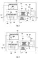
FIGS. 2 and 3 are schematic views of the power module ofFIG. 1 according to one implementation, showing the power module generating electrical power using a flow of compressed gas provided by the stored energy module, and the power module generating electrical power using a flow of high pressure air provided by the scramjet engine, respectively; -
FIGS. 4 and 5 are schematic views of the power module ofFIG. 1 according to another implementation, showing the power module generating electrical power using a flow of mono-propellant provided by the stored energy module, and the power module generating electrical power using a flow of high pressure air provided by the scramjet engine, respectively; -
FIGS. 6 and 7 are schematic views of the power module ofFIG. 1 according to a further implementation, showing the power module generating electrical power using flows of bi-propellant and oxidizer provided by the stored energy module, and the power module generating electrical power using a flow of high pressure air provided by the scramjet engine, respectively; -
FIG. 8 is a chart showing cooperation between the stored energy module and the scramjet engine to generate electrical power with the power modules during flight regimes of a hypersonic vehicle; and -
FIG. 9 is a block diagram of a method of generating electrical power, showing operations of the method. - Reference will now be made to the drawings wherein like reference numerals identify similar structural features or aspects of the subject disclosure. For purposes of explanation and illustration, and not limitation, an exemplary embodiment of a power module in accordance with the disclosure is shown in
FIG. 1 and is designated generally byreference character 100. Other embodiments of power modules, vehicles carrying power modules, and methods of generating electrical power in accordance with the present disclosure, or aspects thereof, are provided inFIGS. 2-9 , as will be described. The systems and methods described herein can be used for generating electric power without an external source of mechanical rotation, such as on hypersonic vehicles employing scramjet engines, though the present disclosure is not limited to generating electrical power or to scramjet vehicles generally. - Referring to
FIG. 1 , avehicle 10, e.g., a hypersonic aircraft, is shown. Thevehicle 10 includes anairframe 12 carrying ascramjet engine 14, one or moreelectrical load 16, and thepower module 100. The one or moreelectrical load 16 is electrically connected to thepower module 100 to receive electrical power P therefrom and can include, for example, avionics, flight control devices, and/or communications equipment. Thescramjet engine 14 is configured for propelling thevehicle 10 at hypersonic speeds and includes aninlet segment 18, an isolator segment 20, acombustor segment 22, and anozzle segment 24. Thenozzle segment 24 is in fluid communication with theinlet segment 18 through thecombustor segment 22 and the isolator segment 20, and during operation thescramj et engine 14 maintains a supersonic airflow therethrough. Ableed port 102 is located within the isolator segment 20 at a high temperature andhigh pressure zone 26 for providingenergy 28 from thescramjet engine 14 to thepower module 100, as will be described. - The
power module 100 includes a turbo-generator 104 with apropellant selector valve 106. The turbo-generator 104 is connected through thepropellant selector valve 106 to both thestored energy module 108 and thescramjet engine 14, the scramjet being connecting to thepropellant selector valve 106 through thebleed air conduit 110. Thepropellant selector valve 106 is arranged to place the turbo-generator 104 in fluid communication with either thestored energy module 108 or thescramjet engine 14 to generate the electrical power P according to the selected source of energy for turbo-generator 104. In the illustrated implementation thepropellant selector valve 106 has a diverter element 112 (shown inFIG. 2 ) with a first position A (shown inFIG. 2 ) and a second position B (shown inFIG. 3 ). - While the
diverter element 112 is in the first position A thepropellant selector valve 106 connects the storedenergy module 108 to the turbo-generator 104 to provideenergy 30 to the turbo-generator from the storedenergy module 108. While thediverter element 112 is in the second position B thepropellant selector valve 106 connects the scramjet engine 14 (shown inFIG. 1 ) to the turbo-generator 104 through the bleed air conduit. The bleed air conduit is in fluid communication with thepropellant selector valve 106 to provideenergy 28 to thepower module 100 from the scramj etengine 14. Although shown and described herein in the context of apropellant selector valve 106 having adiverter element 112 it is to be understood and appreciated that other types of propellant selector valves can be employed and remain within the scope of the present disclosure. - With reference to
FIGS. 2 and 3 , thepower module 100 is shown. Thepower module 100 includes the turbo-generator 104, thepropellant selector valve 106, the storedenergy module 108, and thebleed air conduit 110. Thepower module 100 also includes thediverter element 112, aturbine control valve 105, a storedenergy module conduit 114, aturbine feed conduit 116, and apower converter 118. - The
power converter 118 is electrically connected to the turbo-generator 104 to receive electrical power from the turbo-generator 104. Thepower converter 118 is also connected to the electrical load 16 (shown inFIG. 1 ) and in this respect is configured to convert electrical power p received from the turbo-generator 104 into the electrical power P, which is of a form suitable for the electrical load 16 (shown inFIG. 1 ). In certain embodiments thepower converter 118 includes rectifier circuitry configured to convert alternating current (AC) power into direct current (DC) power. In accordance with certain embodiments thepower converter 118 includes circuitry configured to convert variable frequency AC power into constant frequency AC power, as suitable for an intended application. - The turbo-
generator 104 includes apermanent magnet generator 120 and aturbine 122. Thepermanent magnet generator 120 is operatively associated with theturbine 122 and includes one or morepermanent magnet 124 and one or more coil or stator winding 126. The one or morepermanent magnet 124 is electromagnetically coupled to the one or more coil or stator winding 126. In this respect thepermanent magnet generator 120 is configured to convert mechanical rotation R communicated to thepermanent magnet generator 120 by theturbine 122 into the electrical power p by rotating the one or morepermanent magnet 124 relative to the one or more coil or stator winding 126. In certain embodiments the turbo-generator 104 includes aninterconnect shaft 128, which connects theturbine 122 to thepermanent magnet generator 120 to communicate mechanical rotation R from theturbine 122 into the electrical power p. It is contemplated that theinterconnect shaft 128 directly connect theturbine 122 to thepermanent magnet generator 120, e.g., without an intervening gear train, simplifying the arrangement of thepower module 100 by eliminating the need for an intervening gear assembly, such as an accessory gearbox. - The
turbine 122 is operably connected to thepermanent magnet generator 120 and is further connected to thepropellant selector valve 106 by theturbine feed conduit 116. In this respect theturbine 122 is in fluid communication with thepropellant selector valve 106 through theturbine feed conduit 116 and is configured to receive therefrom the energy 28 (shown inFIG. 1 ) or the energy 30 (shown inFIG. 1 ). More specifically, theenergy 28 is communicated to theturbine 122 from the scramjet engine 14 (shown inFIG. 1 ) through a flow of high temperature andhigh pressure air 130 received from the inlet segment 18 (shown inFIG. 1 ) of thescramjet engine 14. Theenergy 30 is communicated to theturbine 122 through a flow ofcompressed gas 132 from the storedenergy module 108. In both circumstances theturbine 122 expands the received flow of high temperature andhigh pressure air 130 or the flow of thecompressed gas 132, extracts work therefrom, and communicates the work to thepermanent magnet generator 120 as mechanical rotation R for generating the electric power P. - The stored
energy module 108 includes one ormore pressure vessel 134. The one ormore pressure vessel 134 contains thecompressed gas 132 and is connected to thepropellant selector valve 106, and therethrough to theturbine 122. In this respect the storedenergy module 108 is in fluid communication with thepropellant selector valve 106 and is arranged to provide thereto a flow of thecompressed gas 132 selectively, e.g., according to temperature and pressure conditions within thescramjet engine 14. In certain embodiments thecompressed gas 132 can be compressed helium or compressed hydrogen, by way of non-limiting examples. Utilization of helium and/or hydrogen in the storedenergy module 108 simplifies integration of thepower module 100 into the vehicle 10 (shown inFIG. 1 ) due to its availability on certain types of hypersonic vehicles. - The
propellant selector valve 106 includes thediverter element 112 and connects both the storedenergy module conduit 114 and thebleed air conduit 110 to theturbine feed conduit 116. While in the first position A thediverter element 112, and thereby thepropellant selector valve 106, fluidly connects the storedenergy module conduit 114 to theturbine feed conduit 116. So connected, the storedenergy module 108, and more particularly the one ormore pressure vessel 134, provides a flow of thecompressed gas 132 to thepropellant selector valve 106. Thepropellant selector valve 106 in turn communicates the flow of thecompressed gas 132 to theturbine 122 through theturbine feed conduit 116 via theturbine control valve 105, which is configured for throttling the flow of fluid flowing therethrough to control theturbine 122. As will be appreciated by those of skill in the art in view of the present disclosure, the flow of thecompressed gas 132 in turn serves as the source of the mechanical rotation R, which causes thepower module 100 to generate electric power P from the energy 30 (shown inFIG. 1 ). This allows the turbo-generator 104 to generate the electric power P during regimes wherein conditions in the scramjet engine 14 (shown inFIG. 1 ) are ill-suited to provide theenergy 28, such as when thevehicle 10 is operating at subsonic speeds. - With reference to
FIG. 3 , thepower module 100 is shown with thediverter element 112 in the second position B. While in the second position B thediverter element 112, and thereby thepropellant selector valve 106, fluidly connects thebleed air conduit 110 to theturbine feed conduit 116. So connected a flow of the high temperature andhigh pressure air 130 from the inlet segment 18 (shown inFIG. 1 ) of the scramjet engine 14 (shown inFIG. 1 ) provides the energy 28 (shown inFIG. 1 ) to the turbo-generator 104 to generate the electrical power P. Specifically, the flow of the high temperature andhigh pressure air 130 flows throughbleed air conduit 110, through thepropellant selector valve 106, and to theturbine 122 through theturbine feed conduit 116. Theturbine 122 in turn extracts work from the high temperature andhigh pressure air 130 and applies the extracted work as mechanical rotation R to thepermanent magnet generator 120, thereby generating the electrical power P. As will be appreciated by those of skill in the art in view of the present disclosure, the flow of high temperature andhigh pressure air 130 supplements (and in certain embodiments replaces entirely) the flow ofcompressed gas 132 used to generate the electrical power P, allowing the storedenergy module 108 to be commensurately smaller and lighter than otherwise required for a given power requirement during operation of the vehicle 10 (shown inFIG. 1 ). - With reference to
FIGS. 4 and 5 , apower module 200 is shown. Thepower module 200 is similar to the power module 100 (shown inFIG. 1 ) and additionally includes a propellant storedenergy module 208 and agas generator 240 having adecomposition chamber 242. Thegas generator 240 is arranged along theturbine feed conduit 116 and fluidly connects thepropellant selector valve 106 to theturbine 122. It is contemplated that thedecomposition chamber 242 be configured and adapted to decompose a mono-propellant 244 communicated to thedecomposition chamber 242 by thepropellant selector valve 106. In this respect it is contemplated that thedecomposition chamber 242 be configured to decompose the mono-propellant 244, provided by the storedenergy module 208 to thedecomposition chamber 242 by thepropellant selector valve 106, into a flow of high pressure and hightemperature decomposition products 252. Examples of suitable mono-propellants include hydrazine and Otto fuel by way of non-limiting examples. - The stored
energy module 208 includes one or more mono-propellant pressure vessel 246 and one or more pressurizationgas pressure vessel 248. The one or more mono-propellant pressure vessel 246 is in fluid communication with the storedenergy module conduit 114, and therethrough to thegas generator 240 and thedecomposition chamber 242, and contains the mono-propellant 244. The one or more pressurizationgas pressure vessel 248 is connected to the one or more mono-propellant pressure vessel 246, is in fluid communication therewith, and is in fluid communication therethrough with the storedenergy module conduit 114 and thegas generator 240. The one or more pressurizationgas pressure vessel 248 contains apressurization gas 250, such as an inert gas like carbon dioxide or pure nitrogen by way of non-limiting example. Thepressurization gas 250 is partially contained within the one or more mono-propellant pressure vessel 246 to pressurize, and thereby communicate according to the position of thediverter element 112, the mono-propellant 244 contained within the mono-propellant pressure vessel 246. - As shown in
FIG. 4 , while thediverter element 112 is in the first position A, thepropellant selector valve 106 communicates the flow of the mono-propellant 244 to thedecomposition chamber 242. Thedecomposition chamber 242 in turn decomposes the mono-propellant 244 to generate the flow of high temperature and highpressure decomposition products 252, which theturbine feed conduit 116 communicates to theturbine 122. Theturbine 122 expands the high temperature and highpressure decomposition products 252, extracts work therefrom, and applies the extracted work to thegenerator 120 for generating the electric power P. This allows thepower module 200 to generate the electric power P when the energy 28 (shown inFIG. 1 ) is unavailable from the scramjet engine 14 (shown inFIG. 1 ), such as when velocity of the vehicle 10 (shown inFIG. 1 ) is insufficient to pressurize and heat air within the inlet segment 18 (shown inFIG. 1 ) of thescramjet engine 14 to a level sufficient to power the turbo-generator 104. - As shown in
FIG. 5 , while thediverter element 112 is in the second position B the turbineflow control valve 106 fluidly separates the storedenergy module 208 from thegas generator 240 and fluidly connects thebleed air conduit 110 to theturbine feed conduit 116. It is contemplated that thegas generator 240 be configured to convey the flow of the high temperature andhigh pressure air 130 to theturbine 122 of the turbo-generator 104 thereby generating the power P. This allows thepower module 100 to generate the electric power P using the energy 28 (shown inFIG. 1 ) associated with the velocity of the vehicle 10 (shown inFIG. 1 ) when conditions within thescramjet engine 14 are suitable, such as while the vehicle 10 (shown inFIG. 1 ) is cruising at supersonic speeds and the turbo-generator 104 is not consuming the mono-propellant 244 contained within the storedenergy module 208. - With reference to
FIGS. 6 and 7 , apower module 300 is shown. Thepower module 300 is similar to the power module 100 (shown inFIG. 1 ) and additionally includes apropellant selector valve 306, a storedenergy module 308, and agas generator 340 with acombustion chamber 342. Thegas generator 340 is arranged along theturbine feed conduit 116, connects thepropellant selector valve 306 to theturbine 122, and contains within its interior thecombustion chamber 342. Thecombustion chamber 342 is configured and adapted to combust a bi-propellant 344 and anoxidizer 346 communicated to thecombustion chamber 342 by thepropellant selector valve 306. In this respect it is contemplated that thecombustion chamber 342 be configured to oxidize the bi-propellant 344 (e.g., a fuel) and theoxidizer 346 communicated to thecombustion chamber 342 by the storedenergy module 308. Examples of suitable bi-propellants and oxidizers include kerosene-based fuels, such as JP-8, and nitrous oxide by way of non-limiting example. - The stored
energy module 308 includes one or morebi-propellant pressure vessel 348, one or moreoxidizer pressure vessel 350, and one or more pressurizationgas pressure vessel 352. The one or morebi-propellant pressure vessel 348 is in fluid communication with a first storedenergy module conduit 354, and therethrough to thegas generator 340 and thecombustion chamber 342, and contains the bi-propellant 344. The one or moreoxidizer pressure vessel 350 is in fluid communication with a second storedenergy module conduit 356, and therethrough to thegas generator 340 and thecombustion chamber 342, and contains theoxidizer 346. The one or more pressurizationgas pressure vessel 352 is connected to both the one or morebi-propellant pressure vessel 348 and the one or moreoxidizer pressure vessel 350, is in fluid communication therewith, and is in fluid communication therethrough with thepropellant selector valve 306. The one or more pressurizationgas pressure vessel 352 contains apressurization gas 358, such as an inert gas like carbon dioxide or pure nitrogen by way of non-limiting example, for pressurizing thepropellant 344 and theoxidizer 346 contained within the one or morebi-propellant pressure vessel 348 and the one or moreoxidizer pressure vessel 350, respectively. It is contemplated that thepressurization gas 358 be partially contained within the one or morebi-propellant pressure vessel 348 and the one or moreoxidizer pressure vessel 350 to drive the bi-propellant 344 andoxidizer 346 for provision to thegas generator 340 while thepropellant selector valve 306 is in the first position A. - The
propellant selector valve 306 has ashuttle diverter element 360. Theshuttle diverter element 360 is similar to thediverter element 112, and is additionally arranged to connect both the first storedenergy module conduit 354 and the second storedenergy module conduit 356 to thegas generator 340 when in the first position A. As shown inFIG.6 , while theshuttle diverter element 360 is in the first position A, a flow of the bi-propellant 344 and a flow of theoxidizer 346 are communicated by thepropellant selector valve 306 to thegas generator 340. Thegas generator 340 generates a flow of high pressure combustion products 362 using the flow of the bi-propellant 344 and theoxidizer 346, which theturbine feed conduit 116 provides to theturbine 122 of the turbo-generator 104 to generate electrical power P. This allows thepower module 300 to generate electric power P when high temperature air and high pressure air is unavailable from the inlet segment 18 (shown inFIG. 1 ) of the scramjet engine 14 (shown inFIG. 1 ). This allows thepropellant selector valve 306 to provide both a flow of the bi-propellant 344 and a flow of theoxidizer 346 to thegas generator 340, which generators a flow of highpressure combustion products 360 for communication to theturbine 122, from which theturbine 122 extracts mechanical work and communicates to thegenerator 120 for generate electrical power P. - As shown in
FIG. 7 , while thediverter element 112 is in the second position B, thepropellant selector valve 306 fluidly couples the inlet segment 18 (shown inFIG. 1 ) of the scramjet engine 14 (shown inFIG. 1 ) to theturbine 122. Fluidly coupling theinlet segment 18 of thescramjet engine 14 to theturbine 122 causes thepropellant selector valve 306 to communicate the flow of high temperature andhigh pressure air 130 to flow through thebleed air conduit 110 andturbine feed conduit 116 to theturbine 122, communicating the energy 28 (shown inFIG. 1 ) of thescramjet engine 14 to theturbine 122, and the turbo-generator 104 generating electric power P. This allows thepower module 300 to generate the electric power using the energy 28 (shown inFIG. 1 ) associated with the velocity of the vehicle 10 (shown inFIG. 1 ) to generate the electrical power P when the high temperature and high pressure air within theinlet segment 18 of thescramjet engine 14 is suitable, such as during a cruise flight regime of thevehicle 10, without consuming the bi-propellant 344 and theoxidizer 346 within the storedenergy module 308. - It is contemplated that the movement of the
shuttle diverter element 360 between the first position A and the second position B be according to the flight regime of the vehicle 10 (shown inFIG. 1 ). In this respect, when the flight regime of thevehicle 10 does not generate high temperature and high pressure air within the inlet segment 18 (shown inFIG. 1 ) of the scramjet engine 14 (shown inFIG. 1 ) sufficient to provide the energy 28 (shown inFIG. 1 ) necessary to generate the electrical power P, such as during initial acceleration of a flight and during the terminal deceleration of the flight, theshuttle diverter element 306 assumes the first position A. When the flight regime of thevehicle 10 generates high temperature and high pressure air within theinlet segment 18 of the scramjet engine 14 (shown inFIG. 1 ) adequate to provide the energy needed to generate the electrical power P, such as during terminal acceleration, constant velocity flight, and during initial deceleration, the shuttle diverter element assumes the second position B. This allows the weight associated with theoxidizer 346 andfuel 344 contained within theenergy storage module 308 to be limited to that required for subsonic flight of the vehicle 10 (shown inFIG. 1 ) while providing a flow of electrical power throughout the flight, increasing the payload and/or range of thevehicle 10. - With reference to
FIG. 8 , achart 400 of velocity versus flight time is shown for a flight of a vehicle, e.g., the vehicle 10 (shown inFIG. 1 ). Thechart 400 has atrace 402 showing cooperation of scramjet engine energy and stored energy module energy by a power module, e.g., the power module 100 (shown inFIG. 1 ), to generate electrical power during flight of thevehicle 10. As shown inregion 404, electrical power is generated using the energy 30 (shown inFIG. 1 ) provided by the storedenergy module 108 during the initial acceleration of thevehicle 10 by placing the diverter element 112 (shown inFIG. 2 ) in the first position A. Power generation continues using theenergy 30 until the energy level within the inlet segment 18 (shown inFIG. 1 ) of the scramjet engine 14 (shown inFIG. 1 ) reaches apredetermined energy level 406, as indicated the vehicle velocity. Once thepredetermined energy level 406 is reached thediverter element 112 moves to the second position B, and power generation is thereafter accomplished using the energy 28 (shown inFIG. 1 ) provided by thescramjet engine 14, as shown withregion 408. Power generation continues using theenergy 28 until the energy level within theinlet segment 18 drops below thepredetermined energy level 406, as shown withregion 410, at which point thediverter element 112 moves to the first position A, and power generation is accomplished using energy provided by the storedenergy module 108. - In certain embodiments the
diverter element 112 can be passively shuttled. For example, the diverter can move between the first position A and the second position B according to differential pressure (if the energy storage pressure is higher than the scramjet pressure, the delta pressure, between the energy storage pressure and the scramjet pressure, forces the valve to the energy storage open position, but as the scramjet pressure rises, it pushes against the energy storage pressure force, once the scramjet pressure exceeds the energy storage pressure, the valve is shuttled by the differential pressure between the two pressures to passively select the scramjet source). - With reference to
FIG. 9 , a method of generating electrical power is shown. As shown withbox 510, a determination is made with respect to the energy available within the inlet segment of a scramjet engine, e.g., within the inlet segment 18 (shown inFIG. 1 ) of the scramjet engine 14 (shown inFIG. 1 ). When the energy level is below a predetermined level, a stored energy module, e.g., the stored energy module 108 (shown inFIG. 2 ), is placed in fluid communication with a turbo-generator, e.g., the turbo-generator 104 (shown inFIG. 2 ), as shown withbox 520. It is contemplated that fluid communication between the storedenergy module 108 and the turbo-generator be accomplished by moving a diverter element of a propellant selector valve, e.g., the diverter element 112 (shown inFIG. 2 ) of the propellant selector valve 106 (shown inFIG. 2 ), to a first position, e.g., the first position A (shown inFIG. 2 ), as also shown withbox 520. The diverter element is moved to the first position when the energy level is below a predetermined level, as shown withbox 522. Movement of the diverter element can be according to the speed of a vehicle, e.g., of thevehicle 10, as shown withbox 524. Electrical power is thereafter generated for the vehicle using energy provided by the stored energy module, as shown withbox 530. - As shown with
box 540, when the energy level is above the predetermined level the bleed air conduit is placed in fluid communication with the turbo-generator. The bleed air conduit is placed in fluid communication with the turbo-generator by moving the diverter element to the second position, e.g., the second position B (shown inFIG. 3 ) when the energy level is above the predetermined level, as shown withbox 542, and electrical power generated using energy provided by the inlet segment of the scramjet engine through the bleed conduit, as shown withbox 550. - Hypersonic propulsion systems, such as scramjet engines are commonly employed to propel vehicles at hypersonic speeds, typically without the use of rotary elements like gas turbine engine cores and crankshafts on internal combustion engines. While it can simplify the operation of such engines, the absence of a source of mechanical rotation means that electrical power need be provided by a dedicated source of mechanical rotation and a dedicated source of energy. The advantages associated with having a source of electrical power on such aircraft generally justifies the loss of payload space and weight by the energy source carried by such vehicles for power generation.
- In embodiments described herein the energy carried by the vehicle for electrical power generation is augmented by the energy available from the movement of the vehicle. In this respect energy from a stored energy module carried by the vehicle is utilized during flight regimes where energy is unavailable from the engine for electrical power generation, such as during initial acceleration to hypersonic speed and during the terminal portion of deceleration from hypersonic speed at the end of a flight. Between these intervals, e.g., during the terminal portion of acceleration to hypersonic flight, flight at hypersonic speeds, and the initial portion of deceleration from hypersonic speed, energy provided by the engine is used to generate electric power. This reduces the amount of compressed gas, mono-propellant, and/or bi-propellant and oxidizer that the vehicle must carry to generate electrical power during flight, available space and weight for vehicle payload and/or flight duration commensurately increasing.
- The term "about" is intended to include the degree of error associated with measurement of the particular quantity based upon the equipment available at the time of filing the application. For example, "about" can include a range of ± 8% or 5%, or 2% of a given value.
- The terminology used herein is for the purpose of describing particular embodiments only and is not intended to be limiting of the present disclosure. As used herein, the singular forms "a", "an" and "the" are intended to include the plural forms as well, unless the context clearly indicates otherwise. It will be further understood that the terms "comprises" and/or "comprising," when used in this specification, specify the presence of stated features, integers, steps, operations, elements, and/or components, but do not preclude the presence or addition of one or more other features, integers, steps, operations, element components, and/or groups thereof.
- While the present disclosure has been described with reference to an exemplary embodiment or embodiments, it is intended that the present disclosure is not be limited to the particular embodiment disclosed as the best mode contemplated for carrying out this present disclosure, but that the present disclosure will include all embodiments falling within the scope of the claims.
Claims (12)
- A power module for hypersonic vehicles with a scramjet engine, comprising:a turbo-generator (104) with a propellant selector valve (106);a stored energy module (208) connected to the propellant selector valve; anda bleed air conduit (110) connected to the propellant selector valve, wherein the propellant selector valve has a diverter element with a first position and a second position, the stored energy module in fluid communication with the turbo-generator in the first position, and the bleed air conduit in fluid communication with the turbo-generator in the second position and configured to generate electrical power with the turbo-generator using energy provided by an inlet segment of the scramjet engine through the bleed air conduit, and characterised in that the propellant selector valve is configured to move between the first position and the second position according to energy within the inlet segment of the scramjet engine, or wherein the propellant selector valve is configured to move from the first position to the second position when energy within the 2. arr inlet segment of the scramjet engine exceeds a predetermined value.
- The power module as recited in claim 1, further comprising a scramjet engine connected to the propellant selector valve by the bleed air conduit, wherein the scramjet engine has an inlet segment with a bleed port in fluid communication with a nozzle segment through a combustor segment and an isolator segment, wherein the bleed port is in fluid communication with the bleed air conduit.
- The power module as recited in any preceding claim, further comprising a gas generator connecting the propellant selector valve to the turbo-generator.
- The power module as recited in claim 3, wherein the gas generator comprises a decomposition chamber for decomposing a mono-propellant, or wherein the gas generator comprises a combustion chamber for combusting a bi-propellant with an oxidizer.
- The power module as recited in any preceding claim, wherein the stored energy module comprises a pressure vessel, wherein the pressure vessel is connected to the propellant selector valve.
- The power module as recited in claim 5, wherein the stored energy module further comprises a compressed gas contained within the pressure vessel, or wherein the stored energy module further comprises:a mono-propellant contained within the pressure vessel; anda pressurization gas contained within the pressure vessel, wherein the pressurization gas pressurizes the mono-propellant to urge the mono-propellant toward the propellant selector valve, or wherein the pressure vessel is a bi-propellant pressure vessel, the stored energy module further comprising:a bi-propellant contained within the bi-propellant pressure vessel;a pressurization gas pressure vessel connected to the bi-propellant pressure vessel and therethrough in fluid communication with the propellant selector valve; anda pressurization gas contained in the pressurization gas pressure vessel and the bi-propellant pressure vessel and the bi-propellant pressure vessel, the pressurization gas urging the bi-propellant toward the propellant selector valve.
- The power module as recited in claim 5, wherein the pressure vessel is a bi-propellant pressure vessel, the stored energy module further comprising:an oxidizer pressure vessel connected to the propellant selector valve;a pressurization gas pressure vessel connected to the oxidizer pressure vessel and the bi-propellant pressure vessel, the pressurization gas pressure vessel in fluid communication with the turbine speed control valve through both the pressurization gas pressure vessel and the oxidizer pressure vessel.
- The power module as recited in any preceding claim, wherein the turbo-generator comprises:a turbine connected to the propellant selector valve;an interconnect shaft connected to the turbine;a permanent magnet generator operably connected to the turbine by the interconnect shaft.
- A vehicle, comprising:an airframe carrying a scramjet engine and a power module as recited in any preceding claim, wherein the scramjet engine is connected to the propellant selector valve by the bleed air conduit;wherein the stored energy module comprises a pressure vessel, wherein the pressure vessel is connected to the propellant selector valve; andwherein the propellant selector valve is configured to move from the first position to the second position when energy within an inlet segment of the scramjet engine exceeds a predetermined value.
- The vehicle as recited in claim 9, further comprising a compressed gas, a mono-propellant and a pressurization gas, or a bi-propellant and a pressurization gas contained within the pressure vessel.
- A method of generating electrical power, comprising:at a turbo-generator (104) with a propellant selector valve (106), a stored energy module (208) connected to the propellant selector valve, and a bleed air conduit (110) connected to the propellant selector valve having a diverter element with a first position and a second position,placing the stored energy module in fluid communication with the turbo-generator by moving the diverter element to the first position;generating electrical power with the turbo-generator using energy provided by the stored energy module;placing the bleed air conduit in fluid communication with the bleed air conduit by moving the diverter element to the second position; andgenerating electrical power with the turbo-generator using energy provided by an inlet segment of a scramjet engine through the bleed air conduit, and characterised in that the method further comprises:determining an energy level within the inlet segment of the scramjet engine;moving the diverter element to the first position when the energy level is below a predetermined level; andmoving the diverter element to the second position when the energy level is above the predetermined level.
- The method as recited in claim 11, wherein the diverter element is moved between the first position and the second position based on speed of a vehicle carrying the power module.
Applications Claiming Priority (1)
| Application Number | Priority Date | Filing Date | Title |
|---|---|---|---|
| US16/409,307 US20200354070A1 (en) | 2019-05-10 | 2019-05-10 | Power modules for hypersonic vehicles |
Publications (2)
| Publication Number | Publication Date |
|---|---|
| EP3736427A1 EP3736427A1 (en) | 2020-11-11 |
| EP3736427B1 true EP3736427B1 (en) | 2024-02-28 |
Family
ID=68731887
Family Applications (1)
| Application Number | Title | Priority Date | Filing Date |
|---|---|---|---|
| EP19212195.2A Active EP3736427B1 (en) | 2019-05-10 | 2019-11-28 | Power modules for hypersonic vehicles |
Country Status (2)
| Country | Link |
|---|---|
| US (1) | US20200354070A1 (en) |
| EP (1) | EP3736427B1 (en) |
Families Citing this family (3)
| Publication number | Priority date | Publication date | Assignee | Title |
|---|---|---|---|---|
| CN113202655B (en) * | 2021-06-07 | 2022-05-24 | 北京理工大学 | Solid-liquid stamping combined engine |
| US12214889B2 (en) * | 2022-08-11 | 2025-02-04 | Venus Aerospace Corp. | Integral propulsion and auxiliary power generation system for rocket engine powered aircraft |
| US12421920B1 (en) * | 2024-07-26 | 2025-09-23 | Venus Aerospace Corp | Multi-mode rocket-based combined cycle |
Family Cites Families (4)
| Publication number | Priority date | Publication date | Assignee | Title |
|---|---|---|---|---|
| AT358335B (en) * | 1975-10-03 | 1980-09-10 | Gilli Paul Viktor Dipl Ing Dr | DEVICE FOR QUICK START AND / OR SHORT-TIME OVERLOADING OF A GAS TURBINE SET WITH OPEN PROCESS GUIDANCE |
| US4777793A (en) * | 1986-04-14 | 1988-10-18 | Allied-Signal Inc. | Emergency power unit |
| US4864812A (en) * | 1987-11-13 | 1989-09-12 | Sundstrand Corporation | Combined auxiliary and emergency power unit |
| US20160010485A1 (en) * | 2014-07-09 | 2016-01-14 | Aerojet Rocketdyne, Inc. | Combined cycle propulsion system |
-
2019
- 2019-05-10 US US16/409,307 patent/US20200354070A1/en not_active Abandoned
- 2019-11-28 EP EP19212195.2A patent/EP3736427B1/en active Active
Also Published As
| Publication number | Publication date |
|---|---|
| EP3736427A1 (en) | 2020-11-11 |
| US20200354070A1 (en) | 2020-11-12 |
Similar Documents
| Publication | Publication Date | Title |
|---|---|---|
| US8430361B2 (en) | Method and device enabling a rocket engine pump to be driven by an internal combustion engine | |
| US6316841B1 (en) | Integrated emergency power and environmental control system | |
| EP3153690B1 (en) | All co2 aircraft | |
| US9677503B2 (en) | Rocket engine systems | |
| EP3736427B1 (en) | Power modules for hypersonic vehicles | |
| US11319882B2 (en) | Gear and electric amplification of generator motor compressor and turbine drives | |
| CN109764774B (en) | Test device for simulating rocket return landing process | |
| WO1990014511A1 (en) | Aircraft engine starting and emergency power generating system | |
| US12104606B2 (en) | Power modules with regenerative compressor wheels | |
| US12024302B2 (en) | Hybrid starter motor-generator | |
| CN121620478A (en) | Fuel cell turbofan for aircraft | |
| JP2001317406A (en) | Method and apparatus for placing a satellite in low earth orbit | |
| EP1669587B1 (en) | Propulsion system | |
| Koerner | Recent developments in aircraft emergency power | |
| Kobayashi et al. | Hypersonic turbojet engine design of a balloon-based flight testing vehicle | |
| EP3726136B1 (en) | Distributed fuel modules with hydraulic flow circuit breakers and gaseous flow circuit breakers | |
| Jäger et al. | Parametric Study on the Cycle of an electric Hybrid Adaptive Cycle Engine | |
| BRENNAN | Milestones in cryogenic liquid propellant rocket engines | |
| Beremand et al. | An H2-O2 auxiliary power unit for space shuttle | |
| Rudman et al. | Titan IVB launch vehicle and propulsion systems | |
| Beaurain et al. | Earth-to-orbit Rocket Propulsion | |
| Souchier et al. | Earth-to-Orbit Rocket Propulsion | |
| Hoffman | Propulsion for Space Flight | |
| BARDWELL Jr | Aircraft Turbo-Jet and Prop-Jet Starter Systems | |
| Moult | Design and Development of Engines for High-Speed Flight |
Legal Events
| Date | Code | Title | Description |
|---|---|---|---|
| PUAI | Public reference made under article 153(3) epc to a published international application that has entered the european phase |
Free format text: ORIGINAL CODE: 0009012 |
|
| STAA | Information on the status of an ep patent application or granted ep patent |
Free format text: STATUS: THE APPLICATION HAS BEEN PUBLISHED |
|
| AK | Designated contracting states |
Kind code of ref document: A1 Designated state(s): AL AT BE BG CH CY CZ DE DK EE ES FI FR GB GR HR HU IE IS IT LI LT LU LV MC MK MT NL NO PL PT RO RS SE SI SK SM TR |
|
| STAA | Information on the status of an ep patent application or granted ep patent |
Free format text: STATUS: REQUEST FOR EXAMINATION WAS MADE |
|
| 17P | Request for examination filed |
Effective date: 20210510 |
|
| RBV | Designated contracting states (corrected) |
Designated state(s): AL AT BE BG CH CY CZ DE DK EE ES FI FR GB GR HR HU IE IS IT LI LT LU LV MC MK MT NL NO PL PT RO RS SE SI SK SM TR |
|
| STAA | Information on the status of an ep patent application or granted ep patent |
Free format text: STATUS: EXAMINATION IS IN PROGRESS |
|
| 17Q | First examination report despatched |
Effective date: 20220405 |
|
| GRAP | Despatch of communication of intention to grant a patent |
Free format text: ORIGINAL CODE: EPIDOSNIGR1 |
|
| STAA | Information on the status of an ep patent application or granted ep patent |
Free format text: STATUS: GRANT OF PATENT IS INTENDED |
|
| INTG | Intention to grant announced |
Effective date: 20230922 |
|
| GRAS | Grant fee paid |
Free format text: ORIGINAL CODE: EPIDOSNIGR3 |
|
| GRAA | (expected) grant |
Free format text: ORIGINAL CODE: 0009210 |
|
| STAA | Information on the status of an ep patent application or granted ep patent |
Free format text: STATUS: THE PATENT HAS BEEN GRANTED |
|
| AK | Designated contracting states |
Kind code of ref document: B1 Designated state(s): AL AT BE BG CH CY CZ DE DK EE ES FI FR GB GR HR HU IE IS IT LI LT LU LV MC MK MT NL NO PL PT RO RS SE SI SK SM TR |
|
| REG | Reference to a national code |
Ref country code: GB Ref legal event code: FG4D |
|
| REG | Reference to a national code |
Ref country code: CH Ref legal event code: EP |
|
| REG | Reference to a national code |
Ref country code: DE Ref legal event code: R096 Ref document number: 602019047242 Country of ref document: DE |
|
| REG | Reference to a national code |
Ref country code: IE Ref legal event code: FG4D |
|
| REG | Reference to a national code |
Ref country code: LT Ref legal event code: MG9D |
|
| PG25 | Lapsed in a contracting state [announced via postgrant information from national office to epo] |
Ref country code: IS Free format text: LAPSE BECAUSE OF FAILURE TO SUBMIT A TRANSLATION OF THE DESCRIPTION OR TO PAY THE FEE WITHIN THE PRESCRIBED TIME-LIMIT Effective date: 20240628 |
|
| REG | Reference to a national code |
Ref country code: NL Ref legal event code: MP Effective date: 20240228 |
|
| PG25 | Lapsed in a contracting state [announced via postgrant information from national office to epo] |
Ref country code: LT Free format text: LAPSE BECAUSE OF FAILURE TO SUBMIT A TRANSLATION OF THE DESCRIPTION OR TO PAY THE FEE WITHIN THE PRESCRIBED TIME-LIMIT Effective date: 20240228 |
|
| PG25 | Lapsed in a contracting state [announced via postgrant information from national office to epo] |
Ref country code: GR Free format text: LAPSE BECAUSE OF FAILURE TO SUBMIT A TRANSLATION OF THE DESCRIPTION OR TO PAY THE FEE WITHIN THE PRESCRIBED TIME-LIMIT Effective date: 20240529 |
|
| PG25 | Lapsed in a contracting state [announced via postgrant information from national office to epo] |
Ref country code: RS Free format text: LAPSE BECAUSE OF FAILURE TO SUBMIT A TRANSLATION OF THE DESCRIPTION OR TO PAY THE FEE WITHIN THE PRESCRIBED TIME-LIMIT Effective date: 20240528 Ref country code: NL Free format text: LAPSE BECAUSE OF FAILURE TO SUBMIT A TRANSLATION OF THE DESCRIPTION OR TO PAY THE FEE WITHIN THE PRESCRIBED TIME-LIMIT Effective date: 20240228 Ref country code: HR Free format text: LAPSE BECAUSE OF FAILURE TO SUBMIT A TRANSLATION OF THE DESCRIPTION OR TO PAY THE FEE WITHIN THE PRESCRIBED TIME-LIMIT Effective date: 20240228 |
|
| PG25 | Lapsed in a contracting state [announced via postgrant information from national office to epo] |
Ref country code: ES Free format text: LAPSE BECAUSE OF FAILURE TO SUBMIT A TRANSLATION OF THE DESCRIPTION OR TO PAY THE FEE WITHIN THE PRESCRIBED TIME-LIMIT Effective date: 20240228 |
|
| PG25 | Lapsed in a contracting state [announced via postgrant information from national office to epo] |
Ref country code: RS Free format text: LAPSE BECAUSE OF FAILURE TO SUBMIT A TRANSLATION OF THE DESCRIPTION OR TO PAY THE FEE WITHIN THE PRESCRIBED TIME-LIMIT Effective date: 20240528 Ref country code: NO Free format text: LAPSE BECAUSE OF FAILURE TO SUBMIT A TRANSLATION OF THE DESCRIPTION OR TO PAY THE FEE WITHIN THE PRESCRIBED TIME-LIMIT Effective date: 20240528 Ref country code: NL Free format text: LAPSE BECAUSE OF FAILURE TO SUBMIT A TRANSLATION OF THE DESCRIPTION OR TO PAY THE FEE WITHIN THE PRESCRIBED TIME-LIMIT Effective date: 20240228 Ref country code: LT Free format text: LAPSE BECAUSE OF FAILURE TO SUBMIT A TRANSLATION OF THE DESCRIPTION OR TO PAY THE FEE WITHIN THE PRESCRIBED TIME-LIMIT Effective date: 20240228 Ref country code: IS Free format text: LAPSE BECAUSE OF FAILURE TO SUBMIT A TRANSLATION OF THE DESCRIPTION OR TO PAY THE FEE WITHIN THE PRESCRIBED TIME-LIMIT Effective date: 20240628 Ref country code: HR Free format text: LAPSE BECAUSE OF FAILURE TO SUBMIT A TRANSLATION OF THE DESCRIPTION OR TO PAY THE FEE WITHIN THE PRESCRIBED TIME-LIMIT Effective date: 20240228 Ref country code: GR Free format text: LAPSE BECAUSE OF FAILURE TO SUBMIT A TRANSLATION OF THE DESCRIPTION OR TO PAY THE FEE WITHIN THE PRESCRIBED TIME-LIMIT Effective date: 20240529 Ref country code: FI Free format text: LAPSE BECAUSE OF FAILURE TO SUBMIT A TRANSLATION OF THE DESCRIPTION OR TO PAY THE FEE WITHIN THE PRESCRIBED TIME-LIMIT Effective date: 20240228 Ref country code: ES Free format text: LAPSE BECAUSE OF FAILURE TO SUBMIT A TRANSLATION OF THE DESCRIPTION OR TO PAY THE FEE WITHIN THE PRESCRIBED TIME-LIMIT Effective date: 20240228 Ref country code: BG Free format text: LAPSE BECAUSE OF FAILURE TO SUBMIT A TRANSLATION OF THE DESCRIPTION OR TO PAY THE FEE WITHIN THE PRESCRIBED TIME-LIMIT Effective date: 20240228 |
|
| PG25 | Lapsed in a contracting state [announced via postgrant information from national office to epo] |
Ref country code: PL Free format text: LAPSE BECAUSE OF FAILURE TO SUBMIT A TRANSLATION OF THE DESCRIPTION OR TO PAY THE FEE WITHIN THE PRESCRIBED TIME-LIMIT Effective date: 20240228 Ref country code: PT Free format text: LAPSE BECAUSE OF FAILURE TO SUBMIT A TRANSLATION OF THE DESCRIPTION OR TO PAY THE FEE WITHIN THE PRESCRIBED TIME-LIMIT Effective date: 20240628 |
|
| REG | Reference to a national code |
Ref country code: AT Ref legal event code: MK05 Ref document number: 1661452 Country of ref document: AT Kind code of ref document: T Effective date: 20240228 |
|
| PG25 | Lapsed in a contracting state [announced via postgrant information from national office to epo] |
Ref country code: SE Free format text: LAPSE BECAUSE OF FAILURE TO SUBMIT A TRANSLATION OF THE DESCRIPTION OR TO PAY THE FEE WITHIN THE PRESCRIBED TIME-LIMIT Effective date: 20240228 Ref country code: PT Free format text: LAPSE BECAUSE OF FAILURE TO SUBMIT A TRANSLATION OF THE DESCRIPTION OR TO PAY THE FEE WITHIN THE PRESCRIBED TIME-LIMIT Effective date: 20240628 Ref country code: PL Free format text: LAPSE BECAUSE OF FAILURE TO SUBMIT A TRANSLATION OF THE DESCRIPTION OR TO PAY THE FEE WITHIN THE PRESCRIBED TIME-LIMIT Effective date: 20240228 Ref country code: LV Free format text: LAPSE BECAUSE OF FAILURE TO SUBMIT A TRANSLATION OF THE DESCRIPTION OR TO PAY THE FEE WITHIN THE PRESCRIBED TIME-LIMIT Effective date: 20240228 |
|
| PG25 | Lapsed in a contracting state [announced via postgrant information from national office to epo] |
Ref country code: DK Free format text: LAPSE BECAUSE OF FAILURE TO SUBMIT A TRANSLATION OF THE DESCRIPTION OR TO PAY THE FEE WITHIN THE PRESCRIBED TIME-LIMIT Effective date: 20240228 |
|
| PG25 | Lapsed in a contracting state [announced via postgrant information from national office to epo] |
Ref country code: SM Free format text: LAPSE BECAUSE OF FAILURE TO SUBMIT A TRANSLATION OF THE DESCRIPTION OR TO PAY THE FEE WITHIN THE PRESCRIBED TIME-LIMIT Effective date: 20240228 |
|
| PG25 | Lapsed in a contracting state [announced via postgrant information from national office to epo] |
Ref country code: EE Free format text: LAPSE BECAUSE OF FAILURE TO SUBMIT A TRANSLATION OF THE DESCRIPTION OR TO PAY THE FEE WITHIN THE PRESCRIBED TIME-LIMIT Effective date: 20240228 Ref country code: CZ Free format text: LAPSE BECAUSE OF FAILURE TO SUBMIT A TRANSLATION OF THE DESCRIPTION OR TO PAY THE FEE WITHIN THE PRESCRIBED TIME-LIMIT Effective date: 20240228 |
|
| PG25 | Lapsed in a contracting state [announced via postgrant information from national office to epo] |
Ref country code: AT Free format text: LAPSE BECAUSE OF FAILURE TO SUBMIT A TRANSLATION OF THE DESCRIPTION OR TO PAY THE FEE WITHIN THE PRESCRIBED TIME-LIMIT Effective date: 20240228 |
|
| PG25 | Lapsed in a contracting state [announced via postgrant information from national office to epo] |
Ref country code: SK Free format text: LAPSE BECAUSE OF FAILURE TO SUBMIT A TRANSLATION OF THE DESCRIPTION OR TO PAY THE FEE WITHIN THE PRESCRIBED TIME-LIMIT Effective date: 20240228 |
|
| PG25 | Lapsed in a contracting state [announced via postgrant information from national office to epo] |
Ref country code: SM Free format text: LAPSE BECAUSE OF FAILURE TO SUBMIT A TRANSLATION OF THE DESCRIPTION OR TO PAY THE FEE WITHIN THE PRESCRIBED TIME-LIMIT Effective date: 20240228 Ref country code: SK Free format text: LAPSE BECAUSE OF FAILURE TO SUBMIT A TRANSLATION OF THE DESCRIPTION OR TO PAY THE FEE WITHIN THE PRESCRIBED TIME-LIMIT Effective date: 20240228 Ref country code: RO Free format text: LAPSE BECAUSE OF FAILURE TO SUBMIT A TRANSLATION OF THE DESCRIPTION OR TO PAY THE FEE WITHIN THE PRESCRIBED TIME-LIMIT Effective date: 20240228 Ref country code: EE Free format text: LAPSE BECAUSE OF FAILURE TO SUBMIT A TRANSLATION OF THE DESCRIPTION OR TO PAY THE FEE WITHIN THE PRESCRIBED TIME-LIMIT Effective date: 20240228 Ref country code: DK Free format text: LAPSE BECAUSE OF FAILURE TO SUBMIT A TRANSLATION OF THE DESCRIPTION OR TO PAY THE FEE WITHIN THE PRESCRIBED TIME-LIMIT Effective date: 20240228 Ref country code: CZ Free format text: LAPSE BECAUSE OF FAILURE TO SUBMIT A TRANSLATION OF THE DESCRIPTION OR TO PAY THE FEE WITHIN THE PRESCRIBED TIME-LIMIT Effective date: 20240228 Ref country code: AT Free format text: LAPSE BECAUSE OF FAILURE TO SUBMIT A TRANSLATION OF THE DESCRIPTION OR TO PAY THE FEE WITHIN THE PRESCRIBED TIME-LIMIT Effective date: 20240228 |
|
| REG | Reference to a national code |
Ref country code: DE Ref legal event code: R097 Ref document number: 602019047242 Country of ref document: DE |
|
| PG25 | Lapsed in a contracting state [announced via postgrant information from national office to epo] |
Ref country code: IT Free format text: LAPSE BECAUSE OF FAILURE TO SUBMIT A TRANSLATION OF THE DESCRIPTION OR TO PAY THE FEE WITHIN THE PRESCRIBED TIME-LIMIT Effective date: 20240228 |
|
| PG25 | Lapsed in a contracting state [announced via postgrant information from national office to epo] |
Ref country code: IT Free format text: LAPSE BECAUSE OF FAILURE TO SUBMIT A TRANSLATION OF THE DESCRIPTION OR TO PAY THE FEE WITHIN THE PRESCRIBED TIME-LIMIT Effective date: 20240228 |
|
| PLBE | No opposition filed within time limit |
Free format text: ORIGINAL CODE: 0009261 |
|
| STAA | Information on the status of an ep patent application or granted ep patent |
Free format text: STATUS: NO OPPOSITION FILED WITHIN TIME LIMIT |
|
| PGFP | Annual fee paid to national office [announced via postgrant information from national office to epo] |
Ref country code: DE Payment date: 20241022 Year of fee payment: 6 |
|
| PGFP | Annual fee paid to national office [announced via postgrant information from national office to epo] |
Ref country code: GB Payment date: 20241023 Year of fee payment: 6 |
|
| PGFP | Annual fee paid to national office [announced via postgrant information from national office to epo] |
Ref country code: FR Payment date: 20241022 Year of fee payment: 6 |
|
| 26N | No opposition filed |
Effective date: 20241129 |
|
| PG25 | Lapsed in a contracting state [announced via postgrant information from national office to epo] |
Ref country code: SI Free format text: LAPSE BECAUSE OF FAILURE TO SUBMIT A TRANSLATION OF THE DESCRIPTION OR TO PAY THE FEE WITHIN THE PRESCRIBED TIME-LIMIT Effective date: 20240228 |
|
| REG | Reference to a national code |
Ref country code: CH Ref legal event code: PL |
|
| PG25 | Lapsed in a contracting state [announced via postgrant information from national office to epo] |
Ref country code: MC Free format text: LAPSE BECAUSE OF FAILURE TO SUBMIT A TRANSLATION OF THE DESCRIPTION OR TO PAY THE FEE WITHIN THE PRESCRIBED TIME-LIMIT Effective date: 20240228 |
|
| PG25 | Lapsed in a contracting state [announced via postgrant information from national office to epo] |
Ref country code: LU Free format text: LAPSE BECAUSE OF NON-PAYMENT OF DUE FEES Effective date: 20241128 |
|
| REG | Reference to a national code |
Ref country code: CH Ref legal event code: PL |
|
| PG25 | Lapsed in a contracting state [announced via postgrant information from national office to epo] |
Ref country code: CH Free format text: LAPSE BECAUSE OF NON-PAYMENT OF DUE FEES Effective date: 20241130 |
|
| REG | Reference to a national code |
Ref country code: BE Ref legal event code: MM Effective date: 20241130 |
|
| PG25 | Lapsed in a contracting state [announced via postgrant information from national office to epo] |
Ref country code: BE Free format text: LAPSE BECAUSE OF NON-PAYMENT OF DUE FEES Effective date: 20241130 |
|
| PG25 | Lapsed in a contracting state [announced via postgrant information from national office to epo] |
Ref country code: IE Free format text: LAPSE BECAUSE OF NON-PAYMENT OF DUE FEES Effective date: 20241128 |
|
| PG25 | Lapsed in a contracting state [announced via postgrant information from national office to epo] |
Ref country code: HU Free format text: LAPSE BECAUSE OF FAILURE TO SUBMIT A TRANSLATION OF THE DESCRIPTION OR TO PAY THE FEE WITHIN THE PRESCRIBED TIME-LIMIT; INVALID AB INITIO Effective date: 20191128 |
|
| PG25 | Lapsed in a contracting state [announced via postgrant information from national office to epo] |
Ref country code: CY Free format text: LAPSE BECAUSE OF FAILURE TO SUBMIT A TRANSLATION OF THE DESCRIPTION OR TO PAY THE FEE WITHIN THE PRESCRIBED TIME-LIMIT; INVALID AB INITIO Effective date: 20191128 |