EP3736412A1 - Fan inter-blade platform with core and polymer matrix composite skin - Google Patents
Fan inter-blade platform with core and polymer matrix composite skin Download PDFInfo
- Publication number
- EP3736412A1 EP3736412A1 EP20170925.0A EP20170925A EP3736412A1 EP 3736412 A1 EP3736412 A1 EP 3736412A1 EP 20170925 A EP20170925 A EP 20170925A EP 3736412 A1 EP3736412 A1 EP 3736412A1
- Authority
- EP
- European Patent Office
- Prior art keywords
- fan
- core
- gaspath
- platform
- recited
- Prior art date
- Legal status (The legal status is an assumption and is not a legal conclusion. Google has not performed a legal analysis and makes no representation as to the accuracy of the status listed.)
- Granted
Links
Images



Classifications
-
- F—MECHANICAL ENGINEERING; LIGHTING; HEATING; WEAPONS; BLASTING
- F01—MACHINES OR ENGINES IN GENERAL; ENGINE PLANTS IN GENERAL; STEAM ENGINES
- F01D—NON-POSITIVE DISPLACEMENT MACHINES OR ENGINES, e.g. STEAM TURBINES
- F01D11/00—Preventing or minimising internal leakage of working-fluid, e.g. between stages
- F01D11/005—Sealing means between non relatively rotating elements
- F01D11/006—Sealing the gap between rotor blades or blades and rotor
- F01D11/008—Sealing the gap between rotor blades or blades and rotor by spacer elements between the blades, e.g. independent interblade platforms
-
- F—MECHANICAL ENGINEERING; LIGHTING; HEATING; WEAPONS; BLASTING
- F01—MACHINES OR ENGINES IN GENERAL; ENGINE PLANTS IN GENERAL; STEAM ENGINES
- F01D—NON-POSITIVE DISPLACEMENT MACHINES OR ENGINES, e.g. STEAM TURBINES
- F01D5/00—Blades; Blade-carrying members; Heating, heat-insulating, cooling or antivibration means on the blades or the members
- F01D5/30—Fixing blades to rotors; Blade roots ; Blade spacers
- F01D5/3053—Fixing blades to rotors; Blade roots ; Blade spacers by means of pins
-
- F—MECHANICAL ENGINEERING; LIGHTING; HEATING; WEAPONS; BLASTING
- F01—MACHINES OR ENGINES IN GENERAL; ENGINE PLANTS IN GENERAL; STEAM ENGINES
- F01D—NON-POSITIVE DISPLACEMENT MACHINES OR ENGINES, e.g. STEAM TURBINES
- F01D5/00—Blades; Blade-carrying members; Heating, heat-insulating, cooling or antivibration means on the blades or the members
- F01D5/02—Blade-carrying members, e.g. rotors
-
- F—MECHANICAL ENGINEERING; LIGHTING; HEATING; WEAPONS; BLASTING
- F05—INDEXING SCHEMES RELATING TO ENGINES OR PUMPS IN VARIOUS SUBCLASSES OF CLASSES F01-F04
- F05D—INDEXING SCHEME FOR ASPECTS RELATING TO NON-POSITIVE-DISPLACEMENT MACHINES OR ENGINES, GAS-TURBINES OR JET-PROPULSION PLANTS
- F05D2220/00—Application
- F05D2220/30—Application in turbines
- F05D2220/36—Application in turbines specially adapted for the fan of turbofan engines
-
- F—MECHANICAL ENGINEERING; LIGHTING; HEATING; WEAPONS; BLASTING
- F05—INDEXING SCHEMES RELATING TO ENGINES OR PUMPS IN VARIOUS SUBCLASSES OF CLASSES F01-F04
- F05D—INDEXING SCHEME FOR ASPECTS RELATING TO NON-POSITIVE-DISPLACEMENT MACHINES OR ENGINES, GAS-TURBINES OR JET-PROPULSION PLANTS
- F05D2230/00—Manufacture
- F05D2230/20—Manufacture essentially without removing material
- F05D2230/23—Manufacture essentially without removing material by permanently joining parts together
-
- F—MECHANICAL ENGINEERING; LIGHTING; HEATING; WEAPONS; BLASTING
- F05—INDEXING SCHEMES RELATING TO ENGINES OR PUMPS IN VARIOUS SUBCLASSES OF CLASSES F01-F04
- F05D—INDEXING SCHEME FOR ASPECTS RELATING TO NON-POSITIVE-DISPLACEMENT MACHINES OR ENGINES, GAS-TURBINES OR JET-PROPULSION PLANTS
- F05D2240/00—Components
- F05D2240/80—Platforms for stationary or moving blades
-
- F—MECHANICAL ENGINEERING; LIGHTING; HEATING; WEAPONS; BLASTING
- F05—INDEXING SCHEMES RELATING TO ENGINES OR PUMPS IN VARIOUS SUBCLASSES OF CLASSES F01-F04
- F05D—INDEXING SCHEME FOR ASPECTS RELATING TO NON-POSITIVE-DISPLACEMENT MACHINES OR ENGINES, GAS-TURBINES OR JET-PROPULSION PLANTS
- F05D2260/00—Function
- F05D2260/30—Retaining components in desired mutual position
-
- F—MECHANICAL ENGINEERING; LIGHTING; HEATING; WEAPONS; BLASTING
- F05—INDEXING SCHEMES RELATING TO ENGINES OR PUMPS IN VARIOUS SUBCLASSES OF CLASSES F01-F04
- F05D—INDEXING SCHEME FOR ASPECTS RELATING TO NON-POSITIVE-DISPLACEMENT MACHINES OR ENGINES, GAS-TURBINES OR JET-PROPULSION PLANTS
- F05D2300/00—Materials; Properties thereof
- F05D2300/40—Organic materials
- F05D2300/43—Synthetic polymers, e.g. plastics; Rubber
-
- F—MECHANICAL ENGINEERING; LIGHTING; HEATING; WEAPONS; BLASTING
- F05—INDEXING SCHEMES RELATING TO ENGINES OR PUMPS IN VARIOUS SUBCLASSES OF CLASSES F01-F04
- F05D—INDEXING SCHEME FOR ASPECTS RELATING TO NON-POSITIVE-DISPLACEMENT MACHINES OR ENGINES, GAS-TURBINES OR JET-PROPULSION PLANTS
- F05D2300/00—Materials; Properties thereof
- F05D2300/60—Properties or characteristics given to material by treatment or manufacturing
- F05D2300/603—Composites; e.g. fibre-reinforced
-
- Y—GENERAL TAGGING OF NEW TECHNOLOGICAL DEVELOPMENTS; GENERAL TAGGING OF CROSS-SECTIONAL TECHNOLOGIES SPANNING OVER SEVERAL SECTIONS OF THE IPC; TECHNICAL SUBJECTS COVERED BY FORMER USPC CROSS-REFERENCE ART COLLECTIONS [XRACs] AND DIGESTS
- Y02—TECHNOLOGIES OR APPLICATIONS FOR MITIGATION OR ADAPTATION AGAINST CLIMATE CHANGE
- Y02T—CLIMATE CHANGE MITIGATION TECHNOLOGIES RELATED TO TRANSPORTATION
- Y02T50/00—Aeronautics or air transport
- Y02T50/60—Efficient propulsion technologies, e.g. for aircraft
Definitions
- Gas turbine engines typically include a compressor, a combustor, and a turbine that operate in a known manner to rotate a fan to provide thrust.
- the fan includes fan blades that are attached to a hub. There may be platforms between the fan blades near the hub that serve to provide an inner diameter boundary for air entering the fan blades. The platforms are typically secured to the hub, such as by a fastener pin.
- a fan platform comprising a platform body that has gaspath and non-gaspath sides, leading and trailing ends, first and second circumferential sides that are contoured to follow profiles of adjacent fan blades, and lugs projecting from the non-gaspath side that define fastener openings.
- the platform body includes a core and a fiber-reinforced polymer matrix composite skin attached on the core at least on the gaspath and non-gaspath sides.
- the skin is also attached on the lugs.
- the core includes lug stubs, and there are lug pieces adhesively bonded to the lug stubs.
- the lug pieces contain the fastener openings.
- the lug pieces are selected from the group consisting of polymer blocks, metal blocks, and combinations thereof.
- the core is formed of a material selected from the group consisting of honeycomb, foam, and combinations thereof.
- the core is formed of a closed-cell foam.
- the core is bare and exposed on at least a portion of the leading end, the trailing end, the first circumferential side, or the second circumferential side.
- the platform body further includes an environmental barrier layer disposed on at least a portion of the core that does not have the skin.
- the environmental barrier layer is selected from the group consisting of a glass fiber-reinforced material, an elastomer material, and combinations thereof.
- the environmental barrier layer includes a fluoropolymer.
- the fastener openings are axially aligned.
- the core thickens from the leading end to the trailing end.
- the platform body further includes an adhesive between the skin and the core.
- the core includes lug stubs, and there are lug pieces adhesively bonded to the lug stubs.
- the lug pieces contain the fastener openings.
- the core is formed of a material selected from the group consisting of honeycomb, foam, and combinations thereof, and the lug pieces are selected from the group consisting of polymer blocks, metal blocks, and combinations thereof.
- the fan platform is included in a fan of a gas turbine engine that also includes a compressor section, a combustor, and a turbine section.
- the core has lug stubs, and there are lug pieces adhesively bonded to the lug stubs.
- the lug pieces contain the fastener openings.
- the core is formed of a material selected from the group consisting of honeycomb, foam, and combinations thereof, and the lug pieces are selected from the group consisting of polymer blocks, metal blocks, and combinations thereof.
- a method of fabricating a fan platform comprising forming a platform body that has gaspath and non-gaspath sides, leading and trailing ends, first and second circumferential sides that are contoured to follow profiles of adjacent fan blades, and lugs that project from the non-gaspath side and define fastener openings.
- the forming includes arranging one or more layers of a fiber-reinforced polymer matrix composite skin on a core at least on the gaspath and non-gaspath sides.
- An embodiment of the above embodiment the method further comprises, prior to the arranging, adhesively bonding lug pieces to lug stubs on the core.
- the lug pieces contain the fastener openings.
- the method further comprises applying an environmental barrier layer on at least a portion of the core that does not have the skin.
- the environmental barrier layer is selected from the group consisting of a glass fiber-reinforced material, fluoropolymer, and combinations thereof.
- FIG. 1 schematically illustrates a gas turbine engine 20.
- the gas turbine engine 20 is disclosed herein as a two-spool turbofan that generally incorporates a fan section 22, a compressor section 24, a combustor section 26 and a turbine section 28.
- the fan section 22 drives air along a bypass flow path B in a bypass duct defined within a nacelle 15, and also drives air along a core flow path C for compression and communication into the combustor section 26 then expansion through the turbine section 28.
- FIG. 1 schematically illustrates a gas turbine engine 20.
- the gas turbine engine 20 is disclosed herein as a two-spool turbofan that generally incorporates a fan section 22, a compressor section 24, a combustor section 26 and a turbine section 28.
- the fan section 22 drives air along a bypass flow path B in a bypass duct defined within a nacelle 15, and also drives air along a core flow path C for compression and communication into the combustor section 26 then expansion through the turbine section 28.
- FIG. 1 schematic
- the exemplary engine 20 generally includes a low speed spool 30 and a high speed spool 32 mounted for rotation about an engine central longitudinal axis A relative to an engine static structure 36 via several bearing systems 38. It should be understood that various bearing systems 38 at various locations may alternatively or additionally be provided, and the location of bearing systems 38 may be varied as appropriate to the application.
- the low speed spool 30 generally includes an inner shaft 40 that interconnects, a first (or low) pressure compressor 44 and a first (or low) pressure turbine 46.
- the inner shaft 40 is connected to the fan 42 through a speed change mechanism, which in exemplary gas turbine engine 20 is illustrated as a geared architecture 48 to drive a fan 42 at a lower speed than the low speed spool 30.
- the high speed spool 32 includes an outer shaft 50 that interconnects a second (or high) pressure compressor 52 and a second (or high) pressure turbine 54.
- a combustor 56 is arranged in exemplary gas turbine 20 between the high pressure compressor 52 and the high pressure turbine 54.
- a mid-turbine frame 57 of the engine static structure 36 may be arranged generally between the high pressure turbine 54 and the low pressure turbine 46.
- the mid-turbine frame 57 further supports bearing systems 38 in the turbine section 28.
- the inner shaft 40 and the outer shaft 50 are concentric and rotate via bearing systems 38 about the engine central longitudinal axis A which is colline
- the core airflow is compressed by the low pressure compressor 44 then the high pressure compressor 52, mixed and burned with fuel in the combustor 56, then expanded over the high pressure turbine 54 and low pressure turbine 46.
- the mid-turbine frame 57 includes airfoils 59 which are in the core airflow path C.
- the turbines 46, 54 rotationally drive the respective low speed spool 30 and high speed spool 32 in response to the expansion.
- gear system 48 may be located aft of the low pressure compressor, or aft of the combustor section 26 or even aft of turbine section 28, and fan 42 may be positioned forward or aft of the location of gear system 48.
- the engine 20 in one example is a high-bypass geared aircraft engine.
- the engine 20 bypass ratio is greater than about six, with an example embodiment being greater than about ten
- the geared architecture 48 is an epicyclic gear train, such as a planetary gear system or other gear system, with a gear reduction ratio of greater than about 2.3 and the low pressure turbine 46 has a pressure ratio that is greater than about five.
- the engine 20 bypass ratio is greater than about ten
- the fan diameter is significantly larger than that of the low pressure compressor 44
- the low pressure turbine 46 has a pressure ratio that is greater than about five.
- the low pressure turbine 46 pressure ratio is pressure measured prior to the inlet of low pressure turbine 46 as related to the pressure at the outlet of the low pressure turbine 46 prior to an exhaust nozzle.
- the geared architecture 48 may be an epicycle gear train, such as a planetary gear system or other gear system, with a gear reduction ratio of greater than about 2.3:1 and less than about 5:1. It should be understood, however, that the above parameters are only exemplary of one embodiment of a geared architecture engine and that the present invention is applicable to other gas turbine engines including direct drive turbofans.
- the fan section 22 of the engine 20 is designed for a particular flight condition -- typically cruise at about 0.8 Mach and about 35,000 feet (10,668 meters).
- the flight condition of 0.8 Mach and 35,000 ft (10,668 meters), with the engine at its best fuel consumption - also known as "bucket cruise Thrust Specific Fuel Consumption ('TSFC')" - is the industry standard parameter of lbm of fuel being burned divided by lbf of thrust the engine produces at that minimum point.
- "Low fan pressure ratio” is the pressure ratio across the fan blade alone, without a Fan Exit Guide Vane (“FEGV”) system.
- the low fan pressure ratio as disclosed herein according to one non-limiting embodiment is less than about 1.45.
- the "Low corrected fan tip speed” as disclosed herein according to one non-limiting embodiment is less than about 1150 ft / second (350.5 meters/second).
- the example gas turbine engine 20 includes the fan section 22 that comprises in one non-limiting embodiment less than about 26 fan blades 42. In another non-limiting embodiment, the fan section 22 includes less than about 20 fan blades 42. Moreover, in one disclosed embodiment the low pressure turbine 46 includes no more than about 5 turbine rotors. In another disclosed embodiment, the low pressure turbine includes about 6 rotors. In another non-limiting example embodiment, the low pressure turbine 46 includes about 3 turbine rotors. In yet another disclosed embodiment, the number of turbine rotors for the low pressure turbine 46 may be between 3 and 6. A ratio between the number of fan blades 42 and the number of low pressure turbine rotors is between about 3.3 and about 8.6. The example low pressure turbine 46 provides the driving power to rotate the fan section 22 and therefore the relationship between the number of turbine rotors 34 in the low pressure turbine 46 and the number of blades 42 in the fan section 22 disclose an example gas turbine engine 20 with increased power transfer efficiency.
- each fan blade 42 has a root 42a that is received axially into a corresponding slot 60a in the rim of the hub 60.
- the slot 60a radially secures the blade 42.
- the roots 42a are a dovetails and the slots 60a are doveslots.
- each adjacent pair of blades 42 there is a fan platform 62, which is also shown in an elevation view in Figure 3 and a sectional view in Figure 4 .
- the fan platform 62 serves to provide an inner diameter boundary for air coming into the fan blades 42.
- FIGS. 5 and 6 illustrate isolated views of the fan platform 62.
- the fan platform 62 generally includes a platform body 64 that defines a gaspath side 66a, a non-gaspath side 66b, a leading end 66c, a trailing end 66d, a first circumferential side 66e, and a second circumferential side 66f.
- the gaspath side 66a generally faces radially outwards away from the slots 60a in the hub 60, while the non-gaspath side 66b faces radially inwards towards the slots 60a.
- the leading end 66c faces toward the front of the engine 20 and the trailing end 66d faces toward the rear of the engine 20.
- the circumferential sides 66e/66f are contoured to follow the aerodynamic profiles of the adjacent fan blades 42.
- the circumferential sides 66e/66f may abut the blades 42 or interface with seals that abut the blades 42.
- the platform body 64 includes lugs 68a/68b/68c/68d that project from the non-gaspath side 66b.
- the lugs 68a/68b/68c/68d each define a respective fastener opening 70.
- the openings 70 are coaxial such that a fastener 72 ( Figures 3 and 4 ) can be received there through.
- the fastener 72 is also received through corresponding openings 74 in the rim of the hub 60 to secure the fan platform 62 to hub 60.
- one or more bushings 75 can be used with the fastener 72 to facilitate mounting.
- the platform body 64 is formed of several distinct sections. As best shown in Figures 5 and 6 , the platform body 64 includes a core 76 and a fiber-reinforced polymer matrix composite skin 78 attached on the core 76 at least on portions of the gaspath side 66a and non-gaspath side 66b. As an example, the skin 78 is adhesively attached by an adhesive layer 79, such as an epoxy adhesive.
- the core 76 is relatively lightweight and provides a substrate for the skin 78, which is conformal with the core 76.
- the core 76 may be formed of a honeycomb or a foam. One example foam is a closed-cell polymer foam.
- the core 76 thickens in the radial dimension from the leading end 66c to the trailing end 66d (e.g., tapers from the trailing end 66d to the leading end 66c).
- Such a geometry may be used to facilitate meeting space requirements and also enhance bending stiffness.
- the skin 78 is generally strong and durable.
- the skin is formed of a high strength fibers, such as carbon fibers, glass fibers, or aramid fibers, disposed in a polymer matrix, such as an epoxy matrix.
- the fibers are provided as a woven fabric.
- the fibers are unidirectional.
- the skin 78 may be formed of multiple fiber layers, including multiple woven layers, multiple unidirectional layers that alternate in fiber direction, or multiple woven and unidirectional layers.
- the core 76 and skin 78 may have considerable strength, there may be elevated stresses at the lugs 68a/68b/68c/68d.
- the lugs 68a/68b/68c/68d are formed, at least in part, by lug pieces 80 that are composed of a different, stronger material than at least the core 76.
- the lug pieces 80 are formed of blocks of a polymer material or metal which includes the openings 70.
- the polymer material is a reinforced polymer matrix composite.
- the reinforced polymer matrix composite is a laminate formed of multiple fiber layers, such as woven and/or unidirectional fiber layers, disposed in a polymer matrix.
- the fibers of the fiber layers are high strength fibers, such as carbon fibers, and the polymer matrix is epoxy.
- the reinforced polymer matrix composite is a discontinuous fiber composite that includes short fibers disposed in a polymer matrix.
- the metal is aluminum or steel.
- the core 76 includes lug stubs 76a at which the respective lug pieces 80 are attached.
- the lug stubs 76a are relatively short projections that have an interface surface for receiving the lug pieces 80.
- the interface surfaces are flat surfaces that receive and interface with corresponding flat surfaces on the lug pieces 80.
- the lug pieces 80 are adhesively bonded by an adhesive layer 82 to the lug stubs 76a.
- the skin 78 does not completely cover the core 76.
- the skin 78 completely covers the gaspath side 66a and portions of the non-gaspath side 66b but does not cover portions of the lugs 68a/68b/68c/68d, the side of the leading end 66d, the side of the trailing end 66c, or the circumferential sides 66e/66f.
- These portions of the core 76 are thus bare and exposed. If erosion, infiltration of air and/or foreign debris, or other environmental factors are not of concern, those portions may be left bare in the final fan platform 62.
- the fan platform 62 may be provided with an environmental barrier layer 84 on those portions that were bare in the prior example, i.e., the portions of the lugs 68a/68b/68c/68d, the side of the leading end 66d, the side of the trailing end 66c, and the circumferential sides 66e/66f.
- the skin 78 and the environmental barrier layer 84 completely encase the core 76 such that no exterior portion of the core 76 is bare. Even if additional environmental resistance is not desired, the layer 84 may be utilized to strengthen or stiffen the fan platform 62.
- the environmental barrier layer 84 is a glass fiber-reinforced material, an elastomer material, or a combinations thereof.
- the environmental barrier layer 84 is a glass fiber-reinforced material that includes discontinuous glass fibers disposed in a polymer matrix, such as an epoxy matrix.
- the environmental barrier layer 84 includes a fluoropolymer.
- the environmental barrier layer 84 is a continuous layer of the fluoropolymer.
- the fluoropolymer is VITON.
- Figure 8 depicts a method of fabricating the fan platform 62.
- the method generally includes forming the platform body 64 by arranging one or more layers of the fiber-reinforced polymer matrix composite skin 78 on the core 76 at least on portions of the gaspath and non-gaspath sides 66a/66b.
- the core 76 is initially provided without any skin 78 or lug pieces 80 attached.
- the core 76 is provided as a pre-fabricated piece in a desired geometry.
- the core 76 is formed to the desired geometry from a starting or blank shape. For instance, the core 76 is machined or cut from an initial piece of stock foam or honeycomb.
- the lug pieces 80 are attached to the lug stubs 76a by applying the adhesive 82 to the lug stubs 76a, the lug pieces 80, or both and then moving the lug pieces 80 onto the lug stubs 76a. Once the adhesive dries or cures, at least enough to permit handling without inadvertent dislodging, the lug pieces 80 are secured to the core 76.
- one or more layers of the skin 78 are applied to the core 76.
- the layers are fiber layers that are preimpregnated with matrix material
- the layers may be tacky and adhere to the core 76 to permit application without the addition of the adhesive 79.
- the adhesive 79 is applied to the layer, the core 76, or both.
- the fiber layers are dry fiber layers that do not contain any of the matrix material.
- the matrix material may be introduced in a later step, such as by resin transfer, compression molding, or the like.
- a curing step may be conducted to cure the matrix material.
- the curing step involves a thermal curing in which heat is applied above a curing temperature of the matrix material for a period of time until the matrix material is substantially or fully cured.
- the fan platform 62 may still require additional processing steps to achieve a final desired geometry.
- the skin 78 may be trimmed or smoothed and/or the lugs 68a/68b/68c/68d may be machined.
- the lugs 68a/68b/68c/68d initially have a rectangular geometry but are machined to achieve the rounded geometry shown in Figure 6 , which may also serve to reduce weight.
- the environmental barrier layer 84 is used, the environmental barrier layer 84 is then applied at least to the bare regions of the core 76, including those portions exposed by machining. If required, the environmental barrier layer 84 is cured, such as in a thermal curing process. The environmental barrier layer 84 may thereafter be trimmed, smoothed, or machined as appropriate to achieve a final desired geometry.
- the use of the core 76 and skin 78 also permits the fabrication process to be readily adapted for different designs. For instance, it may be desirable that the contour of the aerodynamic gaspath side 66a of the fan platform 62 not be varied from one design to another. Yet, the geometry of the hub 60 may differ between the two designs such that there is more or less design space for the lugs. In this regard, the lugs can be readily redesigned in location and size to accommodate the space available. The fabrication process, however, can remain generally the same between the two designs, as the core 76 and lug pieces 80 are just provided or formed according to the different designs. In contrast, for a platform that is cast or molded, entirely new tooling may be required for the different designs.
Landscapes
- Engineering & Computer Science (AREA)
- Mechanical Engineering (AREA)
- General Engineering & Computer Science (AREA)
- Structures Of Non-Positive Displacement Pumps (AREA)
Abstract
Description
- Gas turbine engines typically include a compressor, a combustor, and a turbine that operate in a known manner to rotate a fan to provide thrust. The fan includes fan blades that are attached to a hub. There may be platforms between the fan blades near the hub that serve to provide an inner diameter boundary for air entering the fan blades. The platforms are typically secured to the hub, such as by a fastener pin.
- In a first aspect of the present invention, there is provided a fan platform comprising a platform body that has gaspath and non-gaspath sides, leading and trailing ends, first and second circumferential sides that are contoured to follow profiles of adjacent fan blades, and lugs projecting from the non-gaspath side that define fastener openings. The platform body includes a core and a fiber-reinforced polymer matrix composite skin attached on the core at least on the gaspath and non-gaspath sides.
- In an embodiment of the above embodiment, the skin is also attached on the lugs.
- In an embodiment of any of the above embodiments, the core includes lug stubs, and there are lug pieces adhesively bonded to the lug stubs. The lug pieces contain the fastener openings.
- In an embodiment of any of the above embodiments, the lug pieces are selected from the group consisting of polymer blocks, metal blocks, and combinations thereof.
- In an embodiment of any of the above embodiments, the core is formed of a material selected from the group consisting of honeycomb, foam, and combinations thereof.
- In an embodiment of any of the above embodiments, the core is formed of a closed-cell foam.
- In an embodiment of any of the above embodiments, the core is bare and exposed on at least a portion of the leading end, the trailing end, the first circumferential side, or the second circumferential side.
- In an embodiment of any of the above embodiments, the platform body further includes an environmental barrier layer disposed on at least a portion of the core that does not have the skin.
- In an embodiment of any of the above embodiments, the environmental barrier layer is selected from the group consisting of a glass fiber-reinforced material, an elastomer material, and combinations thereof.
- In an embodiment of any of the above embodiments, the environmental barrier layer includes a fluoropolymer.
- In an embodiment of any of the above embodiments, the fastener openings are axially aligned.
- In an embodiment of any of the above embodiments, the core thickens from the leading end to the trailing end.
- In an embodiment of any of the above embodiments, the platform body further includes an adhesive between the skin and the core.
- In an embodiment of any of the above embodiments, the core includes lug stubs, and there are lug pieces adhesively bonded to the lug stubs. The lug pieces contain the fastener openings. The core is formed of a material selected from the group consisting of honeycomb, foam, and combinations thereof, and the lug pieces are selected from the group consisting of polymer blocks, metal blocks, and combinations thereof.
- In a second aspect of the present invention, the fan platform is included in a fan of a gas turbine engine that also includes a compressor section, a combustor, and a turbine section.
- In an embodiment of the above embodiment, the core has lug stubs, and there are lug pieces adhesively bonded to the lug stubs. The lug pieces contain the fastener openings. The core is formed of a material selected from the group consisting of honeycomb, foam, and combinations thereof, and the lug pieces are selected from the group consisting of polymer blocks, metal blocks, and combinations thereof.
- In a third aspect of the present invention, there is provided a method of fabricating a fan platform comprising forming a platform body that has gaspath and non-gaspath sides, leading and trailing ends, first and second circumferential sides that are contoured to follow profiles of adjacent fan blades, and lugs that project from the non-gaspath side and define fastener openings. The forming includes arranging one or more layers of a fiber-reinforced polymer matrix composite skin on a core at least on the gaspath and non-gaspath sides.
- An embodiment of the above embodiment the method further comprises, prior to the arranging, adhesively bonding lug pieces to lug stubs on the core. The lug pieces contain the fastener openings.
- In an embodiment of any of the above embodiments the method further comprises applying an environmental barrier layer on at least a portion of the core that does not have the skin. The environmental barrier layer is selected from the group consisting of a glass fiber-reinforced material, fluoropolymer, and combinations thereof.
- The various features and advantages of the present invention will become apparent to those skilled in the art from the following detailed description. The drawings that accompany the detailed description can be briefly described as follows.
-
Figure 1 illustrates an embodiment of a gas turbine engine according to the present invention. -
Figure 2 illustrates selected portions from the fan section of the engine ofFigure 1 . -
Figure 3 illustrates an elevation view of the fan hub, a fan blade, and a fan platform in the fan section ofFigure 2 . -
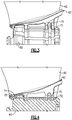
Figure 4 illustrates a sectional view of the joint between the fan platform and the hub ofFigure 2 . -
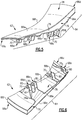
Figure 5 illustrates an isolated view of the fan platform ofFigure 1 . -
Figure 6 illustrates another isolated view of the fan platform ofFigure 1 . -
Figure 7 illustrates an embodiment of a fan platform with an environmental barrier layer according to the present invention. -
Figure 8 depicts an embodiment of a method of fabricating an embodiment of a fan platform according to the present invention. -
Figure 9 illustrates the fan platform ofFigure 8 during fabrication, before a machining operation. -
Figure 10 illustrates an elevation view of the fan platform ofFigure 9 . -
Figure 1 schematically illustrates agas turbine engine 20. Thegas turbine engine 20 is disclosed herein as a two-spool turbofan that generally incorporates afan section 22, acompressor section 24, acombustor section 26 and aturbine section 28. Thefan section 22 drives air along a bypass flow path B in a bypass duct defined within anacelle 15, and also drives air along a core flow path C for compression and communication into thecombustor section 26 then expansion through theturbine section 28. Although depicted as a two-spool turbofan gas turbine engine in the disclosed non-limiting embodiment, it should be understood that the concepts described herein are not limited to use with two-spool turbofans as the teachings may be applied to other types of turbine engines including but not limited to three-spool architectures. - The
exemplary engine 20 generally includes alow speed spool 30 and ahigh speed spool 32 mounted for rotation about an engine central longitudinal axis A relative to an enginestatic structure 36 viaseveral bearing systems 38. It should be understood thatvarious bearing systems 38 at various locations may alternatively or additionally be provided, and the location ofbearing systems 38 may be varied as appropriate to the application. - The
low speed spool 30 generally includes aninner shaft 40 that interconnects, a first (or low)pressure compressor 44 and a first (or low)pressure turbine 46. Theinner shaft 40 is connected to thefan 42 through a speed change mechanism, which in exemplarygas turbine engine 20 is illustrated as a gearedarchitecture 48 to drive afan 42 at a lower speed than thelow speed spool 30. Thehigh speed spool 32 includes anouter shaft 50 that interconnects a second (or high)pressure compressor 52 and a second (or high)pressure turbine 54. Acombustor 56 is arranged inexemplary gas turbine 20 between thehigh pressure compressor 52 and thehigh pressure turbine 54. Amid-turbine frame 57 of the enginestatic structure 36 may be arranged generally between thehigh pressure turbine 54 and thelow pressure turbine 46. Themid-turbine frame 57 further supports bearingsystems 38 in theturbine section 28. Theinner shaft 40 and theouter shaft 50 are concentric and rotate viabearing systems 38 about the engine central longitudinal axis A which is collinear with their longitudinal axes. - The core airflow is compressed by the
low pressure compressor 44 then thehigh pressure compressor 52, mixed and burned with fuel in thecombustor 56, then expanded over thehigh pressure turbine 54 andlow pressure turbine 46. Themid-turbine frame 57 includesairfoils 59 which are in the core airflow path C. Theturbines low speed spool 30 andhigh speed spool 32 in response to the expansion. It will be appreciated that each of the positions of thefan section 22,compressor section 24,combustor section 26,turbine section 28, and fandrive gear system 48 may be varied. For example,gear system 48 may be located aft of the low pressure compressor, or aft of thecombustor section 26 or even aft ofturbine section 28, andfan 42 may be positioned forward or aft of the location ofgear system 48. - The
engine 20 in one example is a high-bypass geared aircraft engine. In a further example, theengine 20 bypass ratio is greater than about six, with an example embodiment being greater than about ten, the gearedarchitecture 48 is an epicyclic gear train, such as a planetary gear system or other gear system, with a gear reduction ratio of greater than about 2.3 and thelow pressure turbine 46 has a pressure ratio that is greater than about five. In one disclosed embodiment, theengine 20 bypass ratio is greater than about ten, the fan diameter is significantly larger than that of thelow pressure compressor 44, and thelow pressure turbine 46 has a pressure ratio that is greater than about five. Thelow pressure turbine 46 pressure ratio is pressure measured prior to the inlet oflow pressure turbine 46 as related to the pressure at the outlet of thelow pressure turbine 46 prior to an exhaust nozzle. The gearedarchitecture 48 may be an epicycle gear train, such as a planetary gear system or other gear system, with a gear reduction ratio of greater than about 2.3:1 and less than about 5:1. It should be understood, however, that the above parameters are only exemplary of one embodiment of a geared architecture engine and that the present invention is applicable to other gas turbine engines including direct drive turbofans. - A significant amount of thrust is provided by the bypass flow B due to the high bypass ratio. The
fan section 22 of theengine 20 is designed for a particular flight condition -- typically cruise at about 0.8 Mach and about 35,000 feet (10,668 meters). The flight condition of 0.8 Mach and 35,000 ft (10,668 meters), with the engine at its best fuel consumption - also known as "bucket cruise Thrust Specific Fuel Consumption ('TSFC')" - is the industry standard parameter of lbm of fuel being burned divided by lbf of thrust the engine produces at that minimum point. "Low fan pressure ratio" is the pressure ratio across the fan blade alone, without a Fan Exit Guide Vane ("FEGV") system. The low fan pressure ratio as disclosed herein according to one non-limiting embodiment is less than about 1.45. "Low corrected fan tip speed" is the actual fan tip speed in ft/sec divided by an industry standard temperature correction of [(Tram °R) / (518.7 °R)]0.5 (where °R = K x 9/5). The "Low corrected fan tip speed" as disclosed herein according to one non-limiting embodiment is less than about 1150 ft / second (350.5 meters/second). - The example
gas turbine engine 20 includes thefan section 22 that comprises in one non-limiting embodiment less than about 26fan blades 42. In another non-limiting embodiment, thefan section 22 includes less than about 20fan blades 42. Moreover, in one disclosed embodiment thelow pressure turbine 46 includes no more than about 5 turbine rotors. In another disclosed embodiment, the low pressure turbine includes about 6 rotors. In another non-limiting example embodiment, thelow pressure turbine 46 includes about 3 turbine rotors. In yet another disclosed embodiment, the number of turbine rotors for thelow pressure turbine 46 may be between 3 and 6. A ratio between the number offan blades 42 and the number of low pressure turbine rotors is between about 3.3 and about 8.6. The examplelow pressure turbine 46 provides the driving power to rotate thefan section 22 and therefore the relationship between the number of turbine rotors 34 in thelow pressure turbine 46 and the number ofblades 42 in thefan section 22 disclose an examplegas turbine engine 20 with increased power transfer efficiency. - Selected portions of the
fan section 22 are shown inFigure 2 . The fan blades 42 (two shown) are attached to afan hub 60. For example, eachfan blade 42 has aroot 42a that is received axially into acorresponding slot 60a in the rim of thehub 60. Theslot 60a radially secures theblade 42. In one embodiment, theroots 42a are a dovetails and theslots 60a are doveslots. - Between each adjacent pair of
blades 42 there is afan platform 62, which is also shown in an elevation view inFigure 3 and a sectional view inFigure 4 . Thefan platform 62 serves to provide an inner diameter boundary for air coming into thefan blades 42. -
Figures 5 and 6 illustrate isolated views of thefan platform 62. Thefan platform 62 generally includes aplatform body 64 that defines agaspath side 66a, anon-gaspath side 66b, aleading end 66c, a trailingend 66d, a firstcircumferential side 66e, and a secondcircumferential side 66f. Thegaspath side 66a generally faces radially outwards away from theslots 60a in thehub 60, while thenon-gaspath side 66b faces radially inwards towards theslots 60a. Theleading end 66c faces toward the front of theengine 20 and the trailingend 66d faces toward the rear of theengine 20. Thecircumferential sides 66e/66f are contoured to follow the aerodynamic profiles of theadjacent fan blades 42. For example, thecircumferential sides 66e/66f may abut theblades 42 or interface with seals that abut theblades 42. - The
platform body 64 includeslugs 68a/68b/68c/68d that project from thenon-gaspath side 66b. Thelugs 68a/68b/68c/68d each define arespective fastener opening 70. For example, theopenings 70 are coaxial such that a fastener 72 (Figures 3 and 4 ) can be received there through. Thefastener 72 is also received through correspondingopenings 74 in the rim of thehub 60 to secure thefan platform 62 tohub 60. Optionally, one ormore bushings 75 can be used with thefastener 72 to facilitate mounting. - The
platform body 64 is formed of several distinct sections. As best shown inFigures 5 and 6 , theplatform body 64 includes acore 76 and a fiber-reinforced polymer matrixcomposite skin 78 attached on the core 76 at least on portions of thegaspath side 66a andnon-gaspath side 66b. As an example, theskin 78 is adhesively attached by anadhesive layer 79, such as an epoxy adhesive. Thecore 76 is relatively lightweight and provides a substrate for theskin 78, which is conformal with thecore 76. As an example, thecore 76 may be formed of a honeycomb or a foam. One example foam is a closed-cell polymer foam. In the illustrated example, thecore 76 thickens in the radial dimension from theleading end 66c to the trailingend 66d (e.g., tapers from the trailingend 66d to theleading end 66c). Such a geometry may be used to facilitate meeting space requirements and also enhance bending stiffness. - The
skin 78 is generally strong and durable. For example, the skin is formed of a high strength fibers, such as carbon fibers, glass fibers, or aramid fibers, disposed in a polymer matrix, such as an epoxy matrix. In one embodiment, the fibers are provided as a woven fabric. In another embodiment, the fibers are unidirectional. In additional embodiments, theskin 78 may be formed of multiple fiber layers, including multiple woven layers, multiple unidirectional layers that alternate in fiber direction, or multiple woven and unidirectional layers. - Although the
core 76 andskin 78 may have considerable strength, there may be elevated stresses at thelugs 68a/68b/68c/68d. In this regard, thelugs 68a/68b/68c/68d are formed, at least in part, bylug pieces 80 that are composed of a different, stronger material than at least the core 76. For example, thelug pieces 80 are formed of blocks of a polymer material or metal which includes theopenings 70. In one embodiment, the polymer material is a reinforced polymer matrix composite. For example, the reinforced polymer matrix composite is a laminate formed of multiple fiber layers, such as woven and/or unidirectional fiber layers, disposed in a polymer matrix. In one further example, the fibers of the fiber layers are high strength fibers, such as carbon fibers, and the polymer matrix is epoxy. In one alternative example, the reinforced polymer matrix composite is a discontinuous fiber composite that includes short fibers disposed in a polymer matrix. In one example of a metal block, the metal is aluminum or steel. - The
core 76 includeslug stubs 76a at which therespective lug pieces 80 are attached. The lug stubs 76a are relatively short projections that have an interface surface for receiving thelug pieces 80. For instance, the interface surfaces are flat surfaces that receive and interface with corresponding flat surfaces on thelug pieces 80. In one example, thelug pieces 80 are adhesively bonded by anadhesive layer 82 to thelug stubs 76a. - As shown in
Figures 5 and 6 , theskin 78 does not completely cover thecore 76. In this example, theskin 78 completely covers thegaspath side 66a and portions of thenon-gaspath side 66b but does not cover portions of thelugs 68a/68b/68c/68d, the side of theleading end 66d, the side of the trailingend 66c, or thecircumferential sides 66e/66f. These portions of the core 76 are thus bare and exposed. If erosion, infiltration of air and/or foreign debris, or other environmental factors are not of concern, those portions may be left bare in thefinal fan platform 62. - Referring to a modified example of the
fan platform 62 inFigure 7 , if greater resistance to environmental factors is desired, thefan platform 62 may be provided with anenvironmental barrier layer 84 on those portions that were bare in the prior example, i.e., the portions of thelugs 68a/68b/68c/68d, the side of theleading end 66d, the side of the trailingend 66c, and thecircumferential sides 66e/66f. In one example, theskin 78 and theenvironmental barrier layer 84 completely encase the core 76 such that no exterior portion of thecore 76 is bare. Even if additional environmental resistance is not desired, thelayer 84 may be utilized to strengthen or stiffen thefan platform 62. - In embodiments, the
environmental barrier layer 84 is a glass fiber-reinforced material, an elastomer material, or a combinations thereof. For instance, theenvironmental barrier layer 84 is a glass fiber-reinforced material that includes discontinuous glass fibers disposed in a polymer matrix, such as an epoxy matrix. In another example, theenvironmental barrier layer 84 includes a fluoropolymer. As an example, theenvironmental barrier layer 84 is a continuous layer of the fluoropolymer. In one embodiment, the fluoropolymer is VITON. -
Figure 8 depicts a method of fabricating thefan platform 62. The method generally includes forming theplatform body 64 by arranging one or more layers of the fiber-reinforced polymer matrixcomposite skin 78 on the core 76 at least on portions of the gaspath andnon-gaspath sides 66a/66b. For instance, as shown, thecore 76 is initially provided without anyskin 78 orlug pieces 80 attached. In one embodiment, thecore 76 is provided as a pre-fabricated piece in a desired geometry. In an alternate example, thecore 76 is formed to the desired geometry from a starting or blank shape. For instance, thecore 76 is machined or cut from an initial piece of stock foam or honeycomb. - Thereafter, the
lug pieces 80 are attached to thelug stubs 76a by applying the adhesive 82 to thelug stubs 76a, thelug pieces 80, or both and then moving thelug pieces 80 onto thelug stubs 76a. Once the adhesive dries or cures, at least enough to permit handling without inadvertent dislodging, thelug pieces 80 are secured to thecore 76. - After securing the
lug pieces 80 to thecore 76, one or more layers of theskin 78 are applied to thecore 76. For instance, if the layers are fiber layers that are preimpregnated with matrix material, the layers may be tacky and adhere to the core 76 to permit application without the addition of the adhesive 79. If the layers are not tacky or are not tacky enough to adhere, the adhesive 79 is applied to the layer, thecore 76, or both. For instance, the fiber layers are dry fiber layers that do not contain any of the matrix material. In this regard, the matrix material may be introduced in a later step, such as by resin transfer, compression molding, or the like. If the matrix material is introduced in this manner, use of a closed-cell foam for thecore 76 prevents the resin from infiltrating from the fiber layer into thecore 76, which could otherwise leave voids in theskin 78. Once the fibers and matrix material are in place on thecore 76, a curing step may be conducted to cure the matrix material. For example, the curing step involves a thermal curing in which heat is applied above a curing temperature of the matrix material for a period of time until the matrix material is substantially or fully cured. - After curing, as shown in
Figure 9 and 10 , thefan platform 62 may still require additional processing steps to achieve a final desired geometry. For instance, theskin 78 may be trimmed or smoothed and/or thelugs 68a/68b/68c/68d may be machined. In the example shown, thelugs 68a/68b/68c/68d initially have a rectangular geometry but are machined to achieve the rounded geometry shown inFigure 6 , which may also serve to reduce weight. If theenvironmental barrier layer 84 is used, theenvironmental barrier layer 84 is then applied at least to the bare regions of the core 76, including those portions exposed by machining. If required, theenvironmental barrier layer 84 is cured, such as in a thermal curing process. Theenvironmental barrier layer 84 may thereafter be trimmed, smoothed, or machined as appropriate to achieve a final desired geometry. - The use of the
core 76 andskin 78 also permits the fabrication process to be readily adapted for different designs. For instance, it may be desirable that the contour of theaerodynamic gaspath side 66a of thefan platform 62 not be varied from one design to another. Yet, the geometry of thehub 60 may differ between the two designs such that there is more or less design space for the lugs. In this regard, the lugs can be readily redesigned in location and size to accommodate the space available. The fabrication process, however, can remain generally the same between the two designs, as thecore 76 andlug pieces 80 are just provided or formed according to the different designs. In contrast, for a platform that is cast or molded, entirely new tooling may be required for the different designs. - Although a combination of features is shown in the illustrated examples, not all of them need to be combined to realize the benefits of various embodiments of this disclosure. In other words, a system designed according to an embodiment of this disclosure will not necessarily include all of the features shown in any one of the Figures or all of the portions schematically shown in the Figures. Moreover, selected features of one example embodiment may be combined with selected features of other example embodiments.
- The preceding description is exemplary rather than limiting in nature. Variations and modifications to the disclosed examples may become apparent to those skilled in the art that do not necessarily depart from this disclosure. The scope of legal protection given to this disclosure can only be determined by studying the following claims.
Claims (15)
- A fan platform (62) comprising:a platform body (64) havinggaspath and non-gaspath sides (66a, 66b),leading and trailing ends (66c, 66d),first and second circumferential sides (66e, 66f) that are contoured to follow profiles of adjacent fan blades (42), andlugs (68a, 68b, 68c, 68d) projecting from the non-gaspath side (66b) and defining fastener openings (70),wherein the platform body (64) comprises a core (76) and a fiber-reinforced polymer matrix composite skin (78) attached on the core (76) at least on the gaspath and non-gaspath sides (66a, 66b).
- The fan platform as recited in claim 1, wherein the skin (78) is also attached on the lugs (68a, 68b, 68c, 68d).
- The fan platform as recited in claim 1 or 2, wherein the core (76) includes lug stubs (76a), and there are lug pieces (80) adhesively bonded to the lug stubs (76a), the lug pieces (80) containing the fastener openings (70).
- The fan platform as recited in claim 3, wherein the lug pieces are selected from the group consisting of polymer blocks, metal blocks, and combinations thereof.
- The fan platform as recited in any of claims 1 to 4, wherein the core (76) is formed of a material selected from the group consisting of honeycomb, foam, and combinations thereof, and optionally the core is formed of a closed-cell foam.
- The fan platform as recited in any of claims 1 to 5, wherein the core (76) is bare and exposed on at least a portion of the leading end (66c), the trailing end (66d), the first circumferential side (66e), or the second circumferential side (66f).
- The fan platform as recited in any of claims 1 to 6, wherein the platform body (64) further comprises an environmental barrier layer (84) disposed on at least a portion of the core (76) that does not have the skin (78).
- The fan platform as recited in claim 7, wherein the environmental barrier layer (84) is selected from the group consisting of a glass fiber-reinforced material, an elastomer material, and combinations thereof, and optionally the environmental barrier layer (84) includes a fluoropolymer.
- The fan platform as recited in any of claims 1 to 8, wherein the fastener openings (70) are axially aligned.
- The fan platform as recited in any of claims 1 to 9, wherein the core (76) thickens from the leading end (66c) to the trailing end (66d).
- The fan platform as recited in any of claims 1 to 10, wherein the platform body (64) further comprises an adhesive (82) between the skin (78) and the core (76).
- A gas turbine engine (20) comprising:a fan (42);a compressor section (24);a combustor (56); anda turbine section (28),wherein the fan (42) includes fan blades and fan platforms (62) according to any of claims 1 to 11 arranged between the fan blades.
- A method of fabricating a fan platform (62), the method comprising:forming a platform body (64) that hasgaspath and non-gaspath sides (66a, 66b),leading and trailing ends (66c, 66d),first and second circumferential sides (66e, 66f) that are contoured to follow profiles of adjacent fan blades (42), andlugs (68a, 68b, 68c, 68d) that project from the non-gaspath side (66b) and define fastener openings (70),by arranging one or more layers of a fiber-reinforced polymer matrix composite skin (78) on a core (76) at least on the gaspath and non-gaspath sides (66a, 66b).
- The method as recited in claim 13, further comprising, prior to the arranging, adhesively bonding lug pieces (80) to lug stubs (76a) on the core (76), the lug pieces (80) containing the fastener openings (70).
- The method as recited in claim 13 or 14, further comprising applying an environmental barrier layer (84) on at least a portion of the core (76) that does not have the skin (78), wherein the environmental barrier layer (84) is selected from the group consisting of a glass fiber-reinforced material, fluoropolymer, and combinations thereof.
Applications Claiming Priority (1)
| Application Number | Priority Date | Filing Date | Title |
|---|---|---|---|
| US16/404,108 US11092021B2 (en) | 2019-05-06 | 2019-05-06 | Fan platform with core and skin |
Publications (2)
| Publication Number | Publication Date |
|---|---|
| EP3736412A1 true EP3736412A1 (en) | 2020-11-11 |
| EP3736412B1 EP3736412B1 (en) | 2024-09-18 |
Family
ID=70417354
Family Applications (1)
| Application Number | Title | Priority Date | Filing Date |
|---|---|---|---|
| EP20170925.0A Active EP3736412B1 (en) | 2019-05-06 | 2020-04-22 | Fan inter-blade platform with core and polymer matrix composite skin |
Country Status (2)
| Country | Link |
|---|---|
| US (1) | US11092021B2 (en) |
| EP (1) | EP3736412B1 (en) |
Cited By (2)
| Publication number | Priority date | Publication date | Assignee | Title |
|---|---|---|---|---|
| FR3109794A1 (en) * | 2020-05-04 | 2021-11-05 | Safran Aircraft Engines | PLATFORM FOR A BLOWER ROTOR OF AN AIRCRAFT TURBOMACHINE |
| EP4163474A3 (en) * | 2021-10-08 | 2023-07-12 | Raytheon Technologies Corporation | Method of repairing a coated inter-blade platform |
Families Citing this family (6)
| Publication number | Priority date | Publication date | Assignee | Title |
|---|---|---|---|---|
| FR3129684B1 (en) * | 2021-11-30 | 2024-08-30 | Safran Aircraft Engines | Bladed wheel platform for turbomachine |
| US12352174B2 (en) * | 2023-02-10 | 2025-07-08 | General Electric Company | Fan retention member for supporting a blade platform of a fan assembly |
| US12234745B1 (en) | 2023-11-03 | 2025-02-25 | General Electric Company | Variable pitch airfoil |
| US12473863B2 (en) | 2024-03-13 | 2025-11-18 | General Electric Company | Gas turbine engine having composite fan blades |
| US12510104B2 (en) | 2024-06-14 | 2025-12-30 | General Electric Company | Gas turbine engine with acoustic spacing of the fan blades and outlet guide vanes |
| US20260063045A1 (en) * | 2024-08-29 | 2026-03-05 | Rtx Corporation | Reinforced Fan Inter-Blade Platforms |
Citations (5)
| Publication number | Priority date | Publication date | Assignee | Title |
|---|---|---|---|---|
| US5281096A (en) * | 1992-09-10 | 1994-01-25 | General Electric Company | Fan assembly having lightweight platforms |
| US5421704A (en) * | 1993-06-10 | 1995-06-06 | Societe Nationale D'etude Et De Construction De Moteurs D'aviation "Snecma" | Inter-blade platform for a bladed disc of a turbomachine rotor |
| US20190112934A1 (en) * | 2017-07-18 | 2019-04-18 | Rolls-Royce Corporation | Annulus filler |
| EP3643885A2 (en) * | 2018-10-16 | 2020-04-29 | United Technologies Corporation | Platform for an airfoil of a gas turbine engine |
| EP3693548A1 (en) * | 2019-02-05 | 2020-08-12 | United Technologies Corporation | Gas turbine engine composite platform |
Family Cites Families (9)
| Publication number | Priority date | Publication date | Assignee | Title |
|---|---|---|---|---|
| US6447250B1 (en) * | 2000-11-27 | 2002-09-10 | General Electric Company | Non-integral fan platform |
| GB0427083D0 (en) * | 2004-12-10 | 2005-01-12 | Rolls Royce Plc | Platform mounted components |
| US9267386B2 (en) * | 2012-06-29 | 2016-02-23 | United Technologies Corporation | Fairing assembly |
| GB201314541D0 (en) | 2013-08-14 | 2013-09-25 | Rolls Royce Plc | Annulus Filler |
| WO2015073096A2 (en) | 2013-09-13 | 2015-05-21 | United Technologies Corporation | Fan platform |
| US20160341071A1 (en) | 2014-01-31 | 2016-11-24 | United Technologies Corporation | Compressed chopped fiber composite fan blade platform |
| FR3029563B1 (en) | 2014-12-08 | 2020-01-17 | Safran Aircraft Engines | LOW HUB RATIO PLATFORM |
| FR3038654B1 (en) | 2015-07-08 | 2017-08-04 | Snecma | ASSEMBLY OF A REPORTED PLATFORM OF BLOWER BLADE ON A BLOWER DISK |
| US9976426B2 (en) * | 2015-07-21 | 2018-05-22 | United Technologies Corporation | Fan platform with stiffening feature |
-
2019
- 2019-05-06 US US16/404,108 patent/US11092021B2/en active Active
-
2020
- 2020-04-22 EP EP20170925.0A patent/EP3736412B1/en active Active
Patent Citations (5)
| Publication number | Priority date | Publication date | Assignee | Title |
|---|---|---|---|---|
| US5281096A (en) * | 1992-09-10 | 1994-01-25 | General Electric Company | Fan assembly having lightweight platforms |
| US5421704A (en) * | 1993-06-10 | 1995-06-06 | Societe Nationale D'etude Et De Construction De Moteurs D'aviation "Snecma" | Inter-blade platform for a bladed disc of a turbomachine rotor |
| US20190112934A1 (en) * | 2017-07-18 | 2019-04-18 | Rolls-Royce Corporation | Annulus filler |
| EP3643885A2 (en) * | 2018-10-16 | 2020-04-29 | United Technologies Corporation | Platform for an airfoil of a gas turbine engine |
| EP3693548A1 (en) * | 2019-02-05 | 2020-08-12 | United Technologies Corporation | Gas turbine engine composite platform |
Cited By (4)
| Publication number | Priority date | Publication date | Assignee | Title |
|---|---|---|---|---|
| FR3109794A1 (en) * | 2020-05-04 | 2021-11-05 | Safran Aircraft Engines | PLATFORM FOR A BLOWER ROTOR OF AN AIRCRAFT TURBOMACHINE |
| WO2021224561A3 (en) * | 2020-05-04 | 2021-12-23 | Safran Aircraft Engines | Platform for a fan rotor of an aircraft turbine engine and associated aircraft turbine engine |
| US11773740B2 (en) | 2020-05-04 | 2023-10-03 | Safran Aircraft Engines | Platform for a fan rotor of an aircraft turbomachine |
| EP4163474A3 (en) * | 2021-10-08 | 2023-07-12 | Raytheon Technologies Corporation | Method of repairing a coated inter-blade platform |
Also Published As
| Publication number | Publication date |
|---|---|
| US11092021B2 (en) | 2021-08-17 |
| US20200355082A1 (en) | 2020-11-12 |
| EP3736412B1 (en) | 2024-09-18 |
Similar Documents
| Publication | Publication Date | Title |
|---|---|---|
| EP3736412B1 (en) | Fan inter-blade platform with core and polymer matrix composite skin | |
| EP3677749B1 (en) | Composite platform with lattice structure | |
| EP3044415B1 (en) | Airfoil with an integrally stiffened composite cover | |
| EP3447306B1 (en) | Fan containment case for gas turbine engine | |
| EP3643885B1 (en) | Platform for an airfoil of a gas turbine engine | |
| US11306601B2 (en) | Pinned airfoil for gas turbine engines | |
| EP3106289B1 (en) | Co-molded metallic fan case containment ring | |
| US10724390B2 (en) | Collar support assembly for airfoils | |
| US11898464B2 (en) | Airfoil for a gas turbine engine | |
| US11391167B2 (en) | Hybrid airfoil for gas turbine engines | |
| EP3913190A1 (en) | Airfoil attachment for gas turbine engines | |
| EP4053382B1 (en) | Composite inter-blade platform | |
| US12503980B2 (en) | Gas turbine engine | |
| US20240301889A1 (en) | Turbomachine and method of assembly | |
| EP4428340B1 (en) | Method for manufacturing a composite bladed disk or rotor | |
| US20240288002A1 (en) | Turbomachine and method of assembly | |
| US20240151147A1 (en) | Airfoil and methods of assembly thereof | |
| CN118273976A (en) | Composite airfoil assembly and method of manufacturing the same | |
| CN121989477A (en) | Methods for manufacturing composite components for gas turbine engines |
Legal Events
| Date | Code | Title | Description |
|---|---|---|---|
| PUAI | Public reference made under article 153(3) epc to a published international application that has entered the european phase |
Free format text: ORIGINAL CODE: 0009012 |
|
| STAA | Information on the status of an ep patent application or granted ep patent |
Free format text: STATUS: THE APPLICATION HAS BEEN PUBLISHED |
|
| AK | Designated contracting states |
Kind code of ref document: A1 Designated state(s): AL AT BE BG CH CY CZ DE DK EE ES FI FR GB GR HR HU IE IS IT LI LT LU LV MC MK MT NL NO PL PT RO RS SE SI SK SM TR |
|
| AX | Request for extension of the european patent |
Extension state: BA ME |
|
| STAA | Information on the status of an ep patent application or granted ep patent |
Free format text: STATUS: REQUEST FOR EXAMINATION WAS MADE |
|
| 17P | Request for examination filed |
Effective date: 20210511 |
|
| RBV | Designated contracting states (corrected) |
Designated state(s): AL AT BE BG CH CY CZ DE DK EE ES FI FR GB GR HR HU IE IS IT LI LT LU LV MC MK MT NL NO PL PT RO RS SE SI SK SM TR |
|
| STAA | Information on the status of an ep patent application or granted ep patent |
Free format text: STATUS: EXAMINATION IS IN PROGRESS |
|
| 17Q | First examination report despatched |
Effective date: 20221031 |
|
| RAP3 | Party data changed (applicant data changed or rights of an application transferred) |
Owner name: RTX CORPORATION |
|
| GRAP | Despatch of communication of intention to grant a patent |
Free format text: ORIGINAL CODE: EPIDOSNIGR1 |
|
| STAA | Information on the status of an ep patent application or granted ep patent |
Free format text: STATUS: GRANT OF PATENT IS INTENDED |
|
| INTG | Intention to grant announced |
Effective date: 20240603 |
|
| GRAS | Grant fee paid |
Free format text: ORIGINAL CODE: EPIDOSNIGR3 |
|
| GRAA | (expected) grant |
Free format text: ORIGINAL CODE: 0009210 |
|
| STAA | Information on the status of an ep patent application or granted ep patent |
Free format text: STATUS: THE PATENT HAS BEEN GRANTED |
|
| AK | Designated contracting states |
Kind code of ref document: B1 Designated state(s): AL AT BE BG CH CY CZ DE DK EE ES FI FR GB GR HR HU IE IS IT LI LT LU LV MC MK MT NL NO PL PT RO RS SE SI SK SM TR |
|
| REG | Reference to a national code |
Ref country code: GB Ref legal event code: FG4D |
|
| REG | Reference to a national code |
Ref country code: CH Ref legal event code: EP |
|
| REG | Reference to a national code |
Ref country code: DE Ref legal event code: R096 Ref document number: 602020037799 Country of ref document: DE |
|
| REG | Reference to a national code |
Ref country code: IE Ref legal event code: FG4D |
|
| REG | Reference to a national code |
Ref country code: LT Ref legal event code: MG9D |
|
| PG25 | Lapsed in a contracting state [announced via postgrant information from national office to epo] |
Ref country code: NO Free format text: LAPSE BECAUSE OF FAILURE TO SUBMIT A TRANSLATION OF THE DESCRIPTION OR TO PAY THE FEE WITHIN THE PRESCRIBED TIME-LIMIT Effective date: 20241218 |
|
| PG25 | Lapsed in a contracting state [announced via postgrant information from national office to epo] |
Ref country code: GR Free format text: LAPSE BECAUSE OF FAILURE TO SUBMIT A TRANSLATION OF THE DESCRIPTION OR TO PAY THE FEE WITHIN THE PRESCRIBED TIME-LIMIT Effective date: 20241219 Ref country code: FI Free format text: LAPSE BECAUSE OF FAILURE TO SUBMIT A TRANSLATION OF THE DESCRIPTION OR TO PAY THE FEE WITHIN THE PRESCRIBED TIME-LIMIT Effective date: 20240918 |
|
| PG25 | Lapsed in a contracting state [announced via postgrant information from national office to epo] |
Ref country code: BG Free format text: LAPSE BECAUSE OF FAILURE TO SUBMIT A TRANSLATION OF THE DESCRIPTION OR TO PAY THE FEE WITHIN THE PRESCRIBED TIME-LIMIT Effective date: 20240918 |
|
| PG25 | Lapsed in a contracting state [announced via postgrant information from national office to epo] |
Ref country code: LV Free format text: LAPSE BECAUSE OF FAILURE TO SUBMIT A TRANSLATION OF THE DESCRIPTION OR TO PAY THE FEE WITHIN THE PRESCRIBED TIME-LIMIT Effective date: 20240918 |
|
| PG25 | Lapsed in a contracting state [announced via postgrant information from national office to epo] |
Ref country code: HR Free format text: LAPSE BECAUSE OF FAILURE TO SUBMIT A TRANSLATION OF THE DESCRIPTION OR TO PAY THE FEE WITHIN THE PRESCRIBED TIME-LIMIT Effective date: 20240918 |
|
| REG | Reference to a national code |
Ref country code: NL Ref legal event code: MP Effective date: 20240918 |
|
| PG25 | Lapsed in a contracting state [announced via postgrant information from national office to epo] |
Ref country code: RS Free format text: LAPSE BECAUSE OF FAILURE TO SUBMIT A TRANSLATION OF THE DESCRIPTION OR TO PAY THE FEE WITHIN THE PRESCRIBED TIME-LIMIT Effective date: 20241218 |
|
| PG25 | Lapsed in a contracting state [announced via postgrant information from national office to epo] |
Ref country code: RS Free format text: LAPSE BECAUSE OF FAILURE TO SUBMIT A TRANSLATION OF THE DESCRIPTION OR TO PAY THE FEE WITHIN THE PRESCRIBED TIME-LIMIT Effective date: 20241218 Ref country code: NO Free format text: LAPSE BECAUSE OF FAILURE TO SUBMIT A TRANSLATION OF THE DESCRIPTION OR TO PAY THE FEE WITHIN THE PRESCRIBED TIME-LIMIT Effective date: 20241218 Ref country code: LV Free format text: LAPSE BECAUSE OF FAILURE TO SUBMIT A TRANSLATION OF THE DESCRIPTION OR TO PAY THE FEE WITHIN THE PRESCRIBED TIME-LIMIT Effective date: 20240918 Ref country code: HR Free format text: LAPSE BECAUSE OF FAILURE TO SUBMIT A TRANSLATION OF THE DESCRIPTION OR TO PAY THE FEE WITHIN THE PRESCRIBED TIME-LIMIT Effective date: 20240918 Ref country code: GR Free format text: LAPSE BECAUSE OF FAILURE TO SUBMIT A TRANSLATION OF THE DESCRIPTION OR TO PAY THE FEE WITHIN THE PRESCRIBED TIME-LIMIT Effective date: 20241219 Ref country code: FI Free format text: LAPSE BECAUSE OF FAILURE TO SUBMIT A TRANSLATION OF THE DESCRIPTION OR TO PAY THE FEE WITHIN THE PRESCRIBED TIME-LIMIT Effective date: 20240918 Ref country code: BG Free format text: LAPSE BECAUSE OF FAILURE TO SUBMIT A TRANSLATION OF THE DESCRIPTION OR TO PAY THE FEE WITHIN THE PRESCRIBED TIME-LIMIT Effective date: 20240918 |
|
| REG | Reference to a national code |
Ref country code: AT Ref legal event code: MK05 Ref document number: 1724850 Country of ref document: AT Kind code of ref document: T Effective date: 20240918 |
|
| PG25 | Lapsed in a contracting state [announced via postgrant information from national office to epo] |
Ref country code: NL Free format text: LAPSE BECAUSE OF FAILURE TO SUBMIT A TRANSLATION OF THE DESCRIPTION OR TO PAY THE FEE WITHIN THE PRESCRIBED TIME-LIMIT Effective date: 20240918 |
|
| PG25 | Lapsed in a contracting state [announced via postgrant information from national office to epo] |
Ref country code: PT Free format text: LAPSE BECAUSE OF FAILURE TO SUBMIT A TRANSLATION OF THE DESCRIPTION OR TO PAY THE FEE WITHIN THE PRESCRIBED TIME-LIMIT Effective date: 20250120 Ref country code: IS Free format text: LAPSE BECAUSE OF FAILURE TO SUBMIT A TRANSLATION OF THE DESCRIPTION OR TO PAY THE FEE WITHIN THE PRESCRIBED TIME-LIMIT Effective date: 20250118 |
|
| PG25 | Lapsed in a contracting state [announced via postgrant information from national office to epo] |
Ref country code: RO Free format text: LAPSE BECAUSE OF FAILURE TO SUBMIT A TRANSLATION OF THE DESCRIPTION OR TO PAY THE FEE WITHIN THE PRESCRIBED TIME-LIMIT Effective date: 20240918 Ref country code: SM Free format text: LAPSE BECAUSE OF FAILURE TO SUBMIT A TRANSLATION OF THE DESCRIPTION OR TO PAY THE FEE WITHIN THE PRESCRIBED TIME-LIMIT Effective date: 20240918 |
|
| PG25 | Lapsed in a contracting state [announced via postgrant information from national office to epo] |
Ref country code: ES Free format text: LAPSE BECAUSE OF FAILURE TO SUBMIT A TRANSLATION OF THE DESCRIPTION OR TO PAY THE FEE WITHIN THE PRESCRIBED TIME-LIMIT Effective date: 20240918 |
|
| PG25 | Lapsed in a contracting state [announced via postgrant information from national office to epo] |
Ref country code: EE Free format text: LAPSE BECAUSE OF FAILURE TO SUBMIT A TRANSLATION OF THE DESCRIPTION OR TO PAY THE FEE WITHIN THE PRESCRIBED TIME-LIMIT Effective date: 20240918 Ref country code: AT Free format text: LAPSE BECAUSE OF FAILURE TO SUBMIT A TRANSLATION OF THE DESCRIPTION OR TO PAY THE FEE WITHIN THE PRESCRIBED TIME-LIMIT Effective date: 20240918 |
|
| PG25 | Lapsed in a contracting state [announced via postgrant information from national office to epo] |
Ref country code: PL Free format text: LAPSE BECAUSE OF FAILURE TO SUBMIT A TRANSLATION OF THE DESCRIPTION OR TO PAY THE FEE WITHIN THE PRESCRIBED TIME-LIMIT Effective date: 20240918 Ref country code: CZ Free format text: LAPSE BECAUSE OF FAILURE TO SUBMIT A TRANSLATION OF THE DESCRIPTION OR TO PAY THE FEE WITHIN THE PRESCRIBED TIME-LIMIT Effective date: 20240918 |
|
| PG25 | Lapsed in a contracting state [announced via postgrant information from national office to epo] |
Ref country code: IT Free format text: LAPSE BECAUSE OF FAILURE TO SUBMIT A TRANSLATION OF THE DESCRIPTION OR TO PAY THE FEE WITHIN THE PRESCRIBED TIME-LIMIT Effective date: 20240918 Ref country code: SK Free format text: LAPSE BECAUSE OF FAILURE TO SUBMIT A TRANSLATION OF THE DESCRIPTION OR TO PAY THE FEE WITHIN THE PRESCRIBED TIME-LIMIT Effective date: 20240918 |
|
| REG | Reference to a national code |
Ref country code: DE Ref legal event code: R097 Ref document number: 602020037799 Country of ref document: DE |
|
| PGFP | Annual fee paid to national office [announced via postgrant information from national office to epo] |
Ref country code: DE Payment date: 20250319 Year of fee payment: 6 |
|
| PG25 | Lapsed in a contracting state [announced via postgrant information from national office to epo] |
Ref country code: DK Free format text: LAPSE BECAUSE OF FAILURE TO SUBMIT A TRANSLATION OF THE DESCRIPTION OR TO PAY THE FEE WITHIN THE PRESCRIBED TIME-LIMIT Effective date: 20240918 |
|
| PLBE | No opposition filed within time limit |
Free format text: ORIGINAL CODE: 0009261 |
|
| STAA | Information on the status of an ep patent application or granted ep patent |
Free format text: STATUS: NO OPPOSITION FILED WITHIN TIME LIMIT |
|
| 26N | No opposition filed |
Effective date: 20250619 |
|
| PG25 | Lapsed in a contracting state [announced via postgrant information from national office to epo] |
Ref country code: SE Free format text: LAPSE BECAUSE OF FAILURE TO SUBMIT A TRANSLATION OF THE DESCRIPTION OR TO PAY THE FEE WITHIN THE PRESCRIBED TIME-LIMIT Effective date: 20240918 |
|
| REG | Reference to a national code |
Ref country code: CH Ref legal event code: H13 Free format text: ST27 STATUS EVENT CODE: U-0-0-H10-H13 (AS PROVIDED BY THE NATIONAL OFFICE) Effective date: 20251125 |
|
| PG25 | Lapsed in a contracting state [announced via postgrant information from national office to epo] |
Ref country code: LU Free format text: LAPSE BECAUSE OF NON-PAYMENT OF DUE FEES Effective date: 20250422 |
|
| PG25 | Lapsed in a contracting state [announced via postgrant information from national office to epo] |
Ref country code: MC Free format text: LAPSE BECAUSE OF FAILURE TO SUBMIT A TRANSLATION OF THE DESCRIPTION OR TO PAY THE FEE WITHIN THE PRESCRIBED TIME-LIMIT Effective date: 20240918 |
|
| REG | Reference to a national code |
Ref country code: BE Ref legal event code: MM Effective date: 20250430 |
|
| PG25 | Lapsed in a contracting state [announced via postgrant information from national office to epo] |
Ref country code: BE Free format text: LAPSE BECAUSE OF NON-PAYMENT OF DUE FEES Effective date: 20250430 |
|
| PG25 | Lapsed in a contracting state [announced via postgrant information from national office to epo] |
Ref country code: CH Free format text: LAPSE BECAUSE OF NON-PAYMENT OF DUE FEES Effective date: 20250430 |
|
| PGFP | Annual fee paid to national office [announced via postgrant information from national office to epo] |
Ref country code: GB Payment date: 20260319 Year of fee payment: 7 |
|
| PG25 | Lapsed in a contracting state [announced via postgrant information from national office to epo] |
Ref country code: IE Free format text: LAPSE BECAUSE OF NON-PAYMENT OF DUE FEES Effective date: 20250422 |
|
| PGFP | Annual fee paid to national office [announced via postgrant information from national office to epo] |
Ref country code: FR Payment date: 20260319 Year of fee payment: 7 |