EP3736359A1 - Materiau ameliore pour le traitement spectro-spatial de signaux optiques - Google Patents
Materiau ameliore pour le traitement spectro-spatial de signaux optiques Download PDFInfo
- Publication number
- EP3736359A1 EP3736359A1 EP20173569.3A EP20173569A EP3736359A1 EP 3736359 A1 EP3736359 A1 EP 3736359A1 EP 20173569 A EP20173569 A EP 20173569A EP 3736359 A1 EP3736359 A1 EP 3736359A1
- Authority
- EP
- European Patent Office
- Prior art keywords
- cation
- level
- transition
- crystal
- representing
- Prior art date
- Legal status (The legal status is an assumption and is not a legal conclusion. Google has not performed a legal analysis and makes no representation as to the accuracy of the status listed.)
- Granted
Links
- ZMIHSKSWHTUOKU-UHFFFAOYSA-N CCC1S(C)CCCC1 Chemical compound CCC1S(C)CCCC1 ZMIHSKSWHTUOKU-UHFFFAOYSA-N 0.000 description 1
- VWCRWJAQBIKZMB-GVHYBUMESA-N C[C@H]1CC(CI)CCC1 Chemical compound C[C@H]1CC(CI)CCC1 VWCRWJAQBIKZMB-GVHYBUMESA-N 0.000 description 1
Images


Classifications
-
- H—ELECTRICITY
- H01—ELECTRIC ELEMENTS
- H01S—DEVICES USING THE PROCESS OF LIGHT AMPLIFICATION BY STIMULATED EMISSION OF RADIATION [LASER] TO AMPLIFY OR GENERATE LIGHT; DEVICES USING STIMULATED EMISSION OF ELECTROMAGNETIC RADIATION IN WAVE RANGES OTHER THAN OPTICAL
- H01S3/00—Lasers, i.e. devices using stimulated emission of electromagnetic radiation in the infrared, visible or ultraviolet wave range
- H01S3/14—Lasers, i.e. devices using stimulated emission of electromagnetic radiation in the infrared, visible or ultraviolet wave range characterised by the material used as the active medium
- H01S3/16—Solid materials
- H01S3/1601—Solid materials characterised by an active (lasing) ion
- H01S3/1603—Solid materials characterised by an active (lasing) ion rare earth
- H01S3/1616—Solid materials characterised by an active (lasing) ion rare earth thulium
-
- C—CHEMISTRY; METALLURGY
- C30—CRYSTAL GROWTH
- C30B—SINGLE-CRYSTAL GROWTH; UNIDIRECTIONAL SOLIDIFICATION OF EUTECTIC MATERIAL OR UNIDIRECTIONAL DEMIXING OF EUTECTOID MATERIAL; REFINING BY ZONE-MELTING OF MATERIAL; PRODUCTION OF A HOMOGENEOUS POLYCRYSTALLINE MATERIAL WITH DEFINED STRUCTURE; SINGLE CRYSTALS OR HOMOGENEOUS POLYCRYSTALLINE MATERIAL WITH DEFINED STRUCTURE; AFTER-TREATMENT OF SINGLE CRYSTALS OR A HOMOGENEOUS POLYCRYSTALLINE MATERIAL WITH DEFINED STRUCTURE; APPARATUS THEREFOR
- C30B29/00—Single crystals or homogeneous polycrystalline material with defined structure characterised by the material or by their shape
- C30B29/10—Inorganic compounds or compositions
- C30B29/16—Oxides
- C30B29/22—Complex oxides
- C30B29/28—Complex oxides with formula A3Me5O12 wherein A is a rare earth metal and Me is Fe, Ga, Sc, Cr, Co or Al, e.g. garnets
Definitions
- the invention relates to the field of reconfigurable and / or broadband spectro-spatial processing of optical signals, and more particularly to the implementation of processing architectures based on spectral hole burning (“spectral hole burning” or SHB in English). ) carried out in an atomic medium with inhomogeneous expansion.
- spectral hole burning spectral hole burning
- the spectral digging methods apply to the processing of optical signals, such as spectral analysis, filtering, correlation, and more particularly to the processing of radar signals (RF frequency) carried optically.
- Other applications also requiring spectro-spatial processing are, for example, acousto-optical imaging, laser stabilization, the detection of digital patterns in RF or broadband communication.
- SHB spectral enhancement
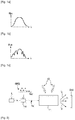
- FIG. 1 A first type of architecture, based on the SHB by writing a processing function in a crystal 11, is illustrated figure 1 .
- the figure 1a illustrates the Abs absorption of crystal 11 as a function of the wavelength ⁇ before programming by SHB and the figure 1b illustrates this same absorption after programming by SHB.
- the SHB is used with a crystal at very low temperature, the latter having to present an inhomogeneous widening of its optical transition at these temperatures.
- the principle of architecture is illustrated figure 1c .
- the objective is to process optical signals, for example unknown RF signals RFS having a complex frequency structure and carried optically: the RFS signal is applied to an optical carrier generated by a laser L via a modulator 14 to form a beam 12.
- the beam 12 consisting of an optical carrier modulated by the RF signal of interest, is incident on the crystal 11, the absorption of which is "Programmed” by entering a processing function as illustrated figure 1c .
- SHB Programming by SHB is carried out by one or more optical beams 13 which illuminate crystal 11. These beams make it possible to shape the absorption of crystal 11 so as to perform a predetermined programming function by increasing the absorption of 11, such as 'illustrated figure 1b .
- An angular dispersion function is programmed into the crystal, as shown figure 1c : an angle is associated with each transmission frequency window, and the incident beam 12 is diffracted on the crystal 11 producing an angular dispersion of the frequency.
- the beam or beams transmitted by crystal 11 are then analyzed via a detector Det so as to extract the desired information on the RFS signal.
- the optical beams 13 are configured to periodically excite the crystal so as to maintain the absorption profile, until a steady state is established. Once the steady state is reached the analysis can be performed 100% of the time.
- FIG. 2 A second type of architecture based on the SHB by recording in the crystal of the signal to be characterized, is illustrated figure 2 .
- the beam 12 directly inscribes its spectrum in the absorption of the crystal 11 by locally widening the absorption for each of its frequencies.
- An example of application of this second type of architecture is the so-called “photographic” spectral analysis.
- a reading beam 15 passes through the programmed crystal 11 and is then detected by a detector Det. This reading beam is spectrally scanned, and rereads the spectrum recorded in the absorption of the material.
- the SHB thus allows the analog processing of radiofrequency signals thanks to the programming of spectro-spatial processing functions in the absorption spectrum of an atomic processor.
- the SHB processing architectures have the advantage of being reconfigurable, that is to say of being able to be used for several functions. For example, in the case of a spectral analyzer, it may be relevant to reconfigure the filter in order to reduce or increase the analysis band as required. It is also necessary to be able to quickly reprogram the filter when it has been accidentally degraded. The reconfiguration speed is then a crucial parameter for minimizing the downtime of the device.
- atomic processors The materials used for these architectures, called “atomic processors”, are generally crystals doped with rare earth ions cooled below 5K.
- the most widely used atomic processor today is the crystal of garnet aluminum and yttrium doped with thulium, denoted Tm 3+ : Y 3 Al 5 O 12 , symbolized by Tm: YAG.
- Tm 3+ the crystal of garnet aluminum and yttrium doped with thulium
- Tm Y 3 Al 5 O 12
- One of the limits of the first type of architecture is the speed of reconfiguration of the processing function and the speed of initialization.
- One of the limits of the second type of architecture is the temporal resolution of the recording.
- the intrinsic spectroscopic properties of the material condition an important part of the performance of SHB architectures.
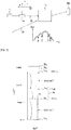
- the figure 3 illustrates the electronic structure of the thulium ion Tm 3+ , optically active ion of the crystal, in a YAG matrix, that is to say the distribution of the energy levels of the thulium ion Tm 3+ and the times of life associated with each level.
- the 3 H 6 level is called the fundamental level
- the 3 H 4 level is called the pumping level.
- the spectral deepening is carried out by excitation of the 3 H 4 pumping level via the optical wave (s) having the wavelength suitable for the 3 H 6 -> 3 H 4 transition, close to 793 nm.
- the intermediate levels 3 H 5 and 3 F 4 are interrelated and can be treated simultaneously as a single metastable level 30.
- the lifetimes of the levels are, for a doping of Tm of 0.5%, of the order of: 3 H 4 : 0.5 ms; 3 H 5: 1 s; 3 F 4 : 15 ms,
- the optical pumping process is a sequential process.
- the atoms are first excited by a laser resonating with the pump level 3 H 4 . Part of the population of Tm 3+ ions is therefore transferred to this 3 H 4 level .
- the ions will return to the ground state either directly radiatively towards the ground level or through the metastable level 3 H 5 and 3 F 4 where they will be stored before relaxing towards the ground level.
- the optical pumping must be repeated a large number of times.
- the typical energy differences of electronic transitions of Tm 3+ are between 14000 and 2000 cm -1 .
- the energy difference between levels 3 H 4 and 3 H 5 of Tm 3+ is about 4500 cm -1 and the energy difference between levels 3 F 4 and 3 H 6 of Tm 3+ is approximately 5500 cm -1 .
- the values of the lifetimes of the different levels of thulium condition the efficiency of the programming, that is to say impose a limit on the speed of reconfiguration (or on the temporal resolution depending on the architecture) and, in to a lesser extent, impose a limit on the contrast programmed structures and therefore the dynamics of analysis. These values also impact the optical pumping efficiency.
- the initialization of the material is done by the repetition of successive light pulses which will ultimately lead to a controlled distribution of populations in the different levels (see figure 3 ).
- a fraction 31 of the population is stored in the 3 H 5 and especially 3 F 4 states of intermediate energy (metastable level).
- This population is then no longer available and does not participate in the initialization step.
- the lifetime of the metastable level 30 is typically of the order of 15 ms, while that of the excited level 3 H 4 is 0.5 ms: due to the presence of the level 3 F 4 having a long lifetime, we observes a bottleneck on this level, which decreases the speed of initialization and reconfigurability (or the temporal resolution according to the architectures), and the efficiency of optical pumping.
- This inhomogeneous width of the absorption line ⁇ inh between the levels 3 H 6 -> 3 H 4 at 793 nm conditions the analysis bandwidth, that is to say the instantaneous processing bandwidth, which is thus limited to about 20 GHz.
- the intrinsic properties of the transition at 793 nm induce a lifetime of the structures optically inscribed in the material of the order of 15 milliseconds without a magnetic field, and an analysis bandwidth. of the order of 15 to 20 GHz.
- Tm 3+ Y 3-x Lu x Al 5 O 12 , with x denoting the average number of lutetium atoms in a molecule of the modified matrix and x between 0.1 and 2.9.
- the publication of A. Ferrier et al, J. Lumin. 194, p116-122 (2018 ) describes the use of Scandium.
- An aim of the present invention is to remedy the aforementioned drawbacks by proposing a new material, as well as its use in a spectral digging device (SHB), exhibiting both reduced lifetimes and an increased inhomogeneous spectral width.
- SHB spectral digging device
- the present invention relates to a crystal for use in a device for spectro-spatial processing of optical signals by spectral digging, of chemical formula Y 3 (1-xy) Tm 3y M 3x Al 5 O 12 with M representing a trivalent cation denoted M 3+ different from thulium and chosen so that it substitutes a part of the trivalent cations yttrium denoted Y 3+ , x representing the degree of substitution of said cation M 3+ , and y representing the degree of substitution of the trivalent cation thulium noted Tm 3+ .
- the M 3+ cation belongs to the Lanthanide family or to the family of transition metals, the Tm 3+ cation has an electronic structure comprising a fundamental level, a pumping level, a metastable intermediate level and a first transition between the level metastable and at the fundamental level, the cation M 3+ exhibits an electronic structure comprising a first resonant transition with said first transition of the Tm 3+ cation.
- the metastable level of the Tm 3+ cation comprises a level called 3 H 5 and a level called 3 F 4
- the first transition of the M 3+ cation is resonant with the first transition of the Tm 3+ cation defined as the transition between the 3 F 4 level and the fundamental level.
- the Tm 3+ cation exhibits a second transition between the pumping level and the metastable level and in which the M 3+ cation exhibits an electronic structure further comprising a second resonant transition with said second transition of the Tm 3 cation. + .
- the first and where appropriate the second transition of the M 3+ cation exhibit an energy difference with the first and, where appropriate, the second transition of the Tm 3+ cation, respectively, of at most 1500 cm ⁇ 1 .
- x is between 0.05 and 0.9.
- y is between 0.001 and 0.05.
- the cation M 3+ is chosen from: Europium, Terbium.
- the crystal has the chemical formula Y 3 (1-xy) Tm 3y M 3x Al 5 O 12 with M representing a trivalent cation noted M 3+ different from thulium and chosen so that it substitutes a part of the trivalent cations yttrium noted Y 3+ , x representing the degree of substitution of said cation M 3+ , and y representing the degree of substitution of the trivalent thulium cation noted Tm 3+ .
- the M 3+ cation belongs to the Lanthanide family or to the family of transition metals.
- the Tm 3+ cation has an electronic structure comprising a fundamental level, a pumping level, a metastable intermediate level and a first transition between the metastable level and the fundamental level.
- the cation M 3+ has an electronic structure comprising a first resonant transition with said first transition of the Tm 3+ cation.
- the objective of the invention is to produce a new crystal optimized for applications for spectro-spatial processing of optical signals (analog or digital signals on an optical carrier) with analysis bands typically between 20 GHz and 200 GHz.
- the invention relates to a CR crystal for use in a device for spectro-spatial processing of optical signals by spectral digging.
- the chemical formula of the crystal according to the invention is Y 3 (1-xy) Tm 3y M 3x Al 5 O 12 , with M representing a trivalent cation denoted M 3+ different from the thulium chosen so that it substitutes a part of the cations yttrium trivalent denoted Y 3+ , x representing the degree of substitution of said cation M 3+ , and y representing the degree of substitution of the trivalent thulium cation denoted Tm 3+ .
- a fraction of the yttrium cations are substituted by thulium cations (rate y being able to be expressed in%) and another fraction of the yttrium ions are substituted by M 3+ cations (rate x) .
- the M 3+ cation belongs to the Lanthanide family or to the family of transition metals.
- the CR crystal according to the invention is derived from the garnet structure, and the presence of the M 3+ cation in the matrix of the crystal according to the invention makes it possible to obtain a material with improved properties for SHB applications, as explained below.
- the Tm 3+ cation has an electronic structure comprising a fundamental level 3 H 6 , a pumping level 3 H 4 and a metastable intermediate level 30.
- a first transition is defined between the metastable level 30 and the fundamental level illustrated. figure 4 .
- the metastable level 30 comprising two levels 3 H 5 and 3 F 4 , this first transition corresponds either to the 3 F 4 ⁇ 3 H 6 transition which we will call T1 (Tm) or to the 3 H 5 ⁇ 3 H 6 transition that we denote by T1 '(Tm).
- the cation M 3+ according to the invention, the electronic structure of which is also illustrated figure 4 , is chosen so as to have an electronic structure comprising at least one transition, called the first transition T1 (M), resonant with the first transition of the cation Tm 3+ , which can be T1 (Tm) or T1 ′ (Tm).
- This first transition T1 (M) is between an “excited” level and the fundamental level.
- resonant level is meant a level whose energy is close to that released by the active ion (here the thulium) during the relaxation step that it is desired to shorten.
- the energy released upon relaxation of the active ion Tm 3+ is transferred to the cation M 3+ and brings the latter into an excited state.
- This energy transfer takes place by an electrostatic coupling (dipole -dipole, dipole-quadrupole) between the Tm ion and the M ion. If this mechanism is resonant and the distance between the Tm and M ions is optimized it can be much faster than radiative relaxation.
- level 3 F 4 improves the speed of initialization and reconfigurability (or of temporal resolution), as well as the efficiency of the optical pumping of a SHB device based on the crystal according to the invention.
- the substituted cations M 3+ exhibit an ionic radius different but close to that of yttrium, so as to be compatible with the substitution of the Y 3+ cations.
- This difference in ionic radius will lead to the appearance of an additional statistical disorder within the crystal structure, which will lead to an increase in the inhomogeneous width.
- This increase in the inhomogeneous width allows the increase in the bandwidth of the spectrum analyzer.
- lutetium and scandium substituents for yttrium known from the state of the art, do not exhibit an electronic structure resonating with the thulium ion. They were chosen only for their compatibility with the garnet matrix and for the introduction of disorder as explained above, to widen the inhomogeneous width of the pumping transition.
- the first transition T1 (M) of the cation M 3+ is resonant with the first transition of the cation Tm 3+ , T1 (M) being defined as the transition between one of the metastable levels and the fundamental level 3 H 6 . Indeed, most of the population being stored in the metastable level, it is preferable to shorten the lifespan of this level as a priority.
- Another way of reducing the population stored in the metastable level is to perform an energy transfer involving the transition T1 ′ defined as the transition between the 3 H 5 level and the fundamental 3 H 6 level .
- this transfer must be efficient enough to take place before the relaxation of the population from level 3 H 5 to level 3 F 4, knowing that this relaxation takes place in a few ⁇ s.
- the cation Tm 3+ presents a second transition between the pumping level 3 H 4 and the metastable level 30.
- This second transition corresponds either to the transition 3 H 4 ⁇ 3 H 5 which we will call T2 (Tm) or to the transition 3 H 4 ⁇ 3 F 4 which we will call T2 '(Tm).
- the cation M 3+ has an electronic structure further comprising a second transition T2 (M) resonating with the second transition of the cation Tm 3+ , T2 (Tm) or T2 ′ (Tm).
- T2 transition of the cation Tm 3+
- T2 (Tm) or T2 ′ (Tm) The energy transfer implemented here is a mechanism similar to that presented previously. To be effective, it also requires energy resonance.
- the first transition T1 (M) preferably has an energy difference with the first transition of the cation Tm 3+ (T1 (Tm) or T1 '(Tm)) substantially equal to +/- 1500 cm -1 .
- the second transition T2 (M) exhibits an energy difference with the second transition of the cation Tm 3+ (T2 (Tm) or T2 ′ (Tm)) of at most 1500 cm ⁇ 1 .
- T2 (Tm) or T2 ′ (Tm) the second transition of the cation Tm 3+
- Tm ion the energy difference between the levels of the Tm ion must be approximately equal to the energy difference between the M levels. This transfer is all the more efficient when it is elastic, that is to say that the energy is conserved.
- the thulium substitution rate y is between 0.001 (0.1%) and 0.05 (5%).
- the rate chosen is related to the desired performance of the SHB device using the crystal according to the invention.
- a value of 0.5% is standard in thulium-doped garnet crystals according to the state of the art.
- doping is used when the substitution rate is low ( ⁇ 10%).
- the value of the rate x is preferably between 0.05 and 0.9.
- the choice of its value is also a function of the desired performance of the SHB device using the crystal according to the invention, more particularly the desired speed / resolution pair of the analyzer.
- the cation M 3+ is europium Eu or terbium Tb.
- the electronic levels of the Eu 3+ cation are shown figure 5 with respect to the levels of thulium described above.
- Europium presents a first transition T1 (Eu) between the level 7 F 6 and the level 7 F 0 exhibiting an energy of approximately 5000 cm -1 resonating with the transition T1 (Tm) of energy 5500 cm -1 . It also presents a second transition T2 (Eu) between the level 7 F 5 and the level 7 F 0 exhibiting an energy of 4000 cm -1 resonating with the transition T2 (Tm) exhibiting an energy of approximately 4500 cm -1 .
- Europium has an ionic radius equal to 1.066 ⁇ , 5% greater than that of yttrium.
- Table 1 illustrates, for different YAG crystals produced with different combinations of values of x and y expressed in%, the values measured, at a temperature of 5K, of the inhomogeneous width ⁇ inh , of the lifetime of the level 3 F 4 and the life time of level 3 H 4 .
- Rate y Tm [% at] 0.4 0.5 0.5 0.5 0.5 0.5 0.8 Rate x Eu [% at] 0 0 1 2 4 6 1
- the lifetime of the metastable 3 F 4 level continues to drop, while that of the excited 3 H 4 level also drops, but to a lesser extent.
- concentration of europium ion is increased, there is a decrease in the distance between the europium ions and the thulium ions. This reduction in distance will lead to an increase in the efficiency of the two transfers T1 and T2.
- inhomogeneous width ⁇ inh increases by approximately 5 GHz per% of Eu 3+ added (at constant% of thulium).
- T 1 representing the lifetime of the pumping level
- ⁇ h corresponding to the homogeneous width which imposes the maximum frequency resolution that can be reached.
- the maximum frequency resolution that can be reached corresponds to 2 times ⁇ h .
- the lower lifetime limit T 1 is 0.4 ⁇ s, and for a desired resolution of 25 kHz the lower lifetime limit T 1 is 12 ⁇ s.
- the resolution of the device is linked to the lifespan of level 3 H 4 . Too short a lifetime would lead to an increase in the homogeneous width and therefore a loss of resolution. Indeed the maximum accessible resolution is equal to twice the homogeneous width (see above).
- the invention relates to a device for spectro-spatial processing of optical signals by spectral digging as described in the state of the art on figures 1 and 2 using a crystal according to the invention.
- the device comprises a laser source L emitting an optical beam, a modulation device 14 configured to modulate the optical beam with an RFS signal, preferably RF, to be analyzed, the crystal CR according to the invention placed in a cryostat at a temperature below 5K, configured to be illuminated by said modulated optical beam 12, and a detector Det configured to detect at least a fraction of an optical beam from the crystal.
- the device according to the invention is not limited to the context of optical processing of microwave signals (spectra analyzer, direction finding, filtering), but can be used in other applications. requiring spectro-spatial processing of optical signals such as acousto-optical imaging or laser stabilization.
Landscapes
- Physics & Mathematics (AREA)
- Electromagnetism (AREA)
- Engineering & Computer Science (AREA)
- Chemical & Material Sciences (AREA)
- Plasma & Fusion (AREA)
- Optics & Photonics (AREA)
- Inorganic Chemistry (AREA)
- Crystallography & Structural Chemistry (AREA)
- Materials Engineering (AREA)
- Metallurgy (AREA)
- Organic Chemistry (AREA)
- Crystals, And After-Treatments Of Crystals (AREA)
- Lasers (AREA)
Abstract
le cation M3+ appartenant à la famille des Lanthanides ou à la famille des métaux de transition,
le cation Tm3+ présentant une structure électronique comprenant un niveau fondamental (3H6), un niveau de pompage (3H4), un niveau intermédiaire métastable (30) et une première transition (T1(Tm), T1'(Tm)) entre le niveau métastable et le niveau fondamental,
le cation M3+ présentant une structure électronique comprenant une première transition (T1(M)) résonnante avec ladite première transition (T1(Tm), T1'(Tm)) du cation Tm3+.
Description
- L'invention concerne le domaine du traitement spectro-spatial de signaux optiques, reconfigurable et/ou large bande, et plus particulièrement sur la mise en œuvre d'architectures de traitement basées sur le creusement spectral (« spectral hole burning » ou SHB en anglais) réalisé dans un milieu atomique à élargissement inhomogène.
- Les méthodes de creusement spectral s'appliquent au traitement de signaux optiques, tels que l'analyse spectrale, le filtrage, la corrélation, et plus particulièrement au traitement de signaux radar (fréquence RF) portés optiquement. D'autres applications nécessitant également un traitement spectro-spatial sont par exemple l'imagerie acousto-optique, la stabilisation laser, la détection de motifs numériques en communication RF ou large bande.
- Le principe de traitement/d'analyse spectrale d'un signal par creusement spectral (SHB) décliné selon deux types d'architecture, est rappelé ci-dessous.
- Un premier type d'architecture, basé sur le SHB par inscription d'une fonction de traitement dans un cristal 11, est illustré
figure 1 . Lafigure 1a illustre l'absorption Abs du cristal 11 en fonction de la longueur d'onde λ avant la programmation par SHB et lafigure 1b illustre cette même absorption après la programmation par SHB. La mise en œuvre du SHB s'effectue avec un cristal à très basse température, ce dernier devant présenter un élargissement inhomogène de sa transition optique à ces températures. - Le principe de l'architecture est illustré
figure 1c . L'objectif est de traiter des signaux optiques, par exemple des signaux RF inconnus RFS présentant une structure fréquentielle complexe et portés optiquement : le signal RFS est appliqué à une porteuse optique générée par un laser L via un modulateur 14 pour former un faisceau 12. Le faisceau 12, constitué d'une porteuse optique modulée par le signal RF d'intérêt, est incident sur le cristal 11 dont l'absorption est « programmée » par inscription d'une fonction de traitement tel qu'illustréfigure 1c . - La programmation par SHB est réalisée par un ou plusieurs faisceaux optiques 13 qui illuminent le cristal 11. Ces faisceaux permettent de façonner l'absorption du cristal 11 de manière à réaliser une fonction de programmation prédéterminée par creusement de l'absorption de 11, tel qu'illustré
figure 1b . - Un exemple d'application de ce premier type d'architecture est l'analyse spectrale dite « arc en ciel».
- Une fonction de dispersion angulaire est programmée dans le cristal, comme illustré
figure 1c : on associe à chaque fenêtre fréquentielle de transmission un angle, et le faisceau 12 incident se diffracte sur le cristal 11 réalisant une dispersion angulaire de la fréquence. Le ou les faisceaux transmis par le cristal 11 sont ensuite analysés via un détecteur Det de manière à extraire l'information souhaitée sur le signal RFS. - Lors de la programmation d'une fonction de filtrage, seule une bande de fréquence prédéfinie du faisceau 12 est transmise par le cristal.
- Les faisceaux optiques 13 sont configurés pour exciter périodiquement le cristal de manière à entretenir le profil d'absorption, jusqu'à l'établissement d'un régime stationnaire. Une fois le régime stationnaire atteint l'analyse peut être effectuée pendant 100% du temps.
- Un deuxième type d'architecture basé sur le SHB par enregistrement dans le cristal du signal à caractériser, est illustré
figure 2 . Ici le faisceau 12 inscrit directement son spectre dans l'absorption du cristal 11 en creusant localement l'absorption pour chacune de ses fréquences. Un exemple d'application de ce deuxième type d'architecture est l'analyse spectrale dite « photographique». - Un faisceau de lecture 15 traverse le cristal programmé 11 et est ensuite détecté par un détecteur Det. Ce faisceau de lecture est balayé spectralement, et vient relire le spectre enregistré dans l'absorption du matériau.
- Le SHB permet ainsi le traitement analogique de signaux radiofréquence grâce à la programmation de fonctions de traitement spectro-spatial dans le spectre d'absorption d'un processeur atomique.
- Les architectures de traitement par SHB présentent l'intérêt d'être reconfigurables, c'est-à-dire de pouvoir être utilisées pour plusieurs fonctions. Par exemple, dans le cas d'un analyseur spectral, il peut être pertinent de reconfigurer le filtre afin de réduire ou augmenter la bande d'analyse en fonction des besoins. Il est également nécessaire d'être en mesure de reprogrammer rapidement le filtre lorsque celui-ci a été accidentellement dégradé. La vitesse de reconfiguration est alors un paramètre crucial pour minimiser les temps morts du dispositif.
- Les matériaux employés pour ces architectures, appelés « processeurs atomiques », sont généralement des cristaux dopés avec des ions terre rare refroidis en dessous de 5K. Le processeur atomique le plus utilisé actuellement est le cristal de grenat d'aluminium et d'yttrium dopé avec du thulium, noté Tm3+ :Y3Al5O12, symbolisé par Tm:YAG. Le creusement spectral s'effectue en modifiant la répartition des populations atomiques des différents niveaux d'énergie intervenant dans le processus.
- Une des limites du premier type d'architecture est la vitesse de reconfiguration de la fonction de traitement et la vitesse d'initialisation. Une des limites du deuxième type d'architecture est la résolution temporelle de l'enregistrement.
- Ces limites trouvent leur source dans la valeur du temps de vie des excitations atomiques dans le matériau, comme expliqué ci-dessous.
- De manière plus générale les propriétés spectroscopiques intrinsèques du matériau conditionnent une part importante des performances des architectures de SHB.
- La
figure 3 illustre la structure électronique de l'ion thulium Tm3+, ion optiquement actif du cristal, dans une matrice YAG, c'est-à-dire la répartition des niveaux d'énergie de l'ion thulium Tm3+ et les temps de vie associés à chaque niveau. - Le niveau 3H6 est dénommé niveau fondamental, le niveau 3H4 est dénommé niveau de pompage. Le creusement spectral s'effectue par excitation du niveau 3H4 de pompage via la ou les ondes optiques présentant la longueur d'onde adaptée à la transition 3H6 -> 3H4, proche de 793 nm.
- Les niveaux intermédiaires 3H5 et 3F4 sont liés entre eux et peuvent être traités simultanément comme un seul niveau métastable 30.
- Les temps de vie des niveaux sont, pour un dopage de Tm de 0.5%, de l'ordre de :
3H4: 0.5 ms; 3H5 : 1 µs ; 3F4: 15 ms, - Le processus de pompage optique est un processus séquentiel. Les atomes sont tout d'abord excités par un laser résonnant avec le niveau de pompage 3H4. Une partie de la population des ions Tm3+ est donc transférée vers ce niveau 3H4. Dans un second temps les ions vont retourner vers l'état fondamental soit directement de manière radiative vers le niveau fondamental soit en passant par le niveau métastable 3H5 et 3F4 où ils vont être stockés avant de relaxer vers le niveau fondamental. Pour être efficace le pompage optique doit être répété un grand nombre de fois.
- Les différences d'énergie typiques des transitions électroniques du Tm3+ sont comprises entre 14000 et 2000 cm-1. Par exemple la différence d'énergie entre les niveaux 3H4 et 3H5 du Tm3+ est d'environ 4500 cm-1 et la différence d'énergie entre les niveaux 3F4 et 3H6 du Tm3+ est d'environ 5500 cm-1.
- Les valeurs des temps de vie des différents niveaux du thulium conditionnent l'efficacité de la programmation, c'est-à-dire imposent une limite à la vitesse de reconfiguration (ou à la résolution temporelle en fonction de l'architecture) et, dans une moindre mesure, imposent une limite sur le contraste des structures programmées et donc la dynamique d'analyse. Ces valeurs impactent également l'efficacité de pompage optique.
- En effet, l'initialisation du matériau se fait par la répétition d'impulsions lumineuses successives qui aboutiront in fine à une répartition contrôlée des populations dans les différents niveaux (voir
figure 3 ). Au cours de ce processus, une fraction 31 de la population est stockée dans les états 3H5 et surtout 3F4 d'énergie intermédiaire (niveau métastable). Cette population n'est alors plus disponible et ne participe pas à l'étape d'initialisation. La durée de vie du niveau métastable 30 est typiquement de l'ordre de 15 ms, alors que celle du niveau excité 3H4 est de 0.5 ms : du fait de la présence du niveau 3F4 présentant un long temps de vie, on observe un goulot d'étranglement («bottleneck» en anglais) sur ce niveau, qui diminue la vitesse d'initialisation et de reconfigurabilité (ou la résolution temporelle selon les architectures), et l'efficacité de pompage optique. - Le caractère inhomogène de la raie d'absorption ΔΓinh de la transition entre les niveaux 3H6 -> 3H4 (pompage) provient du fait que la matrice de YAG possède des défauts et n'est pas parfaitement périodique. Du fait de ce désordre chacun des ions thulium voit ainsi un environnement local légèrement spécifique et différent de celui des autres, ce qui crée un élargissement inhomogène de la fréquence de la raie à 793 nm de 20 GHz, pour un échantillon dopé à 0.5% en Tm3+.
- Cette largeur inhomogène de la raie d'absorption ΔΓinh entre les niveaux 3H6 -> 3H4 à 793 nm conditionne la bande passante d'analyse, c'est-à-dire la bande passante instantanée de traitement, qui est ainsi limitée à environ 20 GHz.
- Ainsi, dans le YAG dopé thulium Tm : YAG, les propriétés intrinsèques de la transition à 793 nm induisent un temps de vie des structures inscrites optiquement dans le matériau de l'ordre de 15 millisecondes sans champ magnétique, et une bande passante d'analyse de l'ordre de 15 à 20 GHz.
- Pour des applications de traitement ou d'analyse spectrale de signaux radar large bande (après transposition dans le domaine optique), ou d'analyse de signaux numériques très grand débit, il est souhaitable:
- de pouvoir reconfigurer la fonction de traitement en un temps inférieur à la milliseconde (contre 15 ms pour le Tm :YAG),
- d'améliorer la résolution temporelle de l'enregistrement, à mieux que la milliseconde (limitée à 15 ms pour le Tm :YAG),
- d'augmenter la bande passante de traitement à 40 GHz voire au-delà (contre 20 GHz pour le Tm:YAG), compte tenu de l'augmentation continue en fréquence des bandes d'intérêt du spectre électromagnétique, et du débit de plus en plus élevé des communications numériques.
- Le problème du temps de vie est adressé dans l'état de l'art :
- en utilisant une excitation lumineuse intense pour « effacer » la fonction ou le signal inscrit, avec l'inconvénient que les puissances nécessaires à un effacement rapide sont en général élevées, et donc contraignantes sur la technologie de la source optique ainsi que sur la cryogénie (la température usuelle d'utilisation de ces matériaux étant de quelques Kelvins),
- en augmentant le taux de dopage du matériau, ce qui réduit les temps de vie des populations des niveaux métastable et excité par le biais de la relaxation croisée. Ce phénomène se produit lorsqu'un ion possède trois niveaux d'énergie tels que leurs écarts sont presque égaux. L'échange d'énergie qui a lieu entre un ion dans son état fondamental et un deuxième ion dans son état excité provoque l'excitation du premier et la désexcitation du second, de sorte qu'ils se retrouvent dans le niveau intermédiaire. Cela se produit par exemple dans le Tm:YAG pour des taux de dopage supérieurs à 2%, tel que décrit dans la publication de G. Armagan et al., Optical Materials 1, pp11-20 (1992). Cela entraîne toutefois une augmentation de la largeur homogène du Tm, ce qui dégrade la résolution spectrale du dispositif.
- Pour augmenter la bande passante de traitement, c'est-à-dire la largeur inhomogène ΔΓinh du Tm :YAG, une solution est d'introduire une autre terre rare dans la matrice de YAG. Ce composé se substitue partiellement à l'ion yttrium et crée autour de lui des contraintes mécaniques qui modifient de manière permanente la structure cristalline et donc l'environnement des ions Tm. Le document
US8829471 décrit l'utilisation d'une matrice de YAG modifiée avec du lutécium, de formule Tm :YLuAG ou plus précisément : - Tm3+:Y3-xLuxAl5O12, avec x désignant le nombre moyen d'atomes de lutécium dans une molécule de la matrice modifiée et x compris entre 0.1 et 2.9. La publication de A. Ferrier et al, J.Lumin. 194, p116-122 (2018) décrit l'utilisation du Scandium.
- Cependant aucun de ces cristaux ne modifie significativement les valeurs des temps de vie des niveaux de l'ion thulium, et les limitations liées à ces valeurs demeurent.
- Un but de la présente invention est de remédier aux inconvénients précités en proposant un nouveau matériau, ainsi que son utilisation dans un dispositif de creusement spectral (SHB), présentant à la fois des temps de vie réduits et une largeur spectrale inhomogène augmentée.
- La présente invention a pour objet un cristal pour une utilisation dans un dispositif de traitement spectro-spatial de signaux optique par creusement spectral, de formule chimique Y3(1-x-y) Tm3yM3xAl5O12 avec M représentant un cation trivalent noté M3+ différent du thulium et choisi de sorte qu'il substitue une partie des cations trivalents yttrium notés Y3+, x représentant le taux de substitution dudit cation M3+, et y représentant le taux de substitution du cation trivalent thulium noté Tm3+. Le cation M3+ appartient à la famille des Lanthanides ou à la famille des Métaux de transition, le cation Tm3+ présente une structure électronique comprenant un niveau fondamental, un niveau de pompage, un niveau intermédiaire métastable et une première transition entre le niveau métastable et le niveau fondamental, le cation M3+ présente une structure électronique comprenant une première transition résonnante avec ladite première transition du cation Tm3+.
- Selon un mode de réalisation le niveau métastable du cation Tm3+ comprend un niveau dénommé 3H5 et un niveau dénommé 3F4, et la première transition du cation M3+ est résonnante avec la première transition du cation Tm3+ définie comme la transition entre le niveau 3F4 et le niveau fondamental.
- Selon un mode de réalisation le cation Tm3+ présente une deuxième transition entre le niveau de pompage et le niveau métastable et dans lequel le cation M3+ présente une structure électronique comprenant en outre une deuxième transition résonnante avec ladite deuxième transition du cation Tm3+.
- Préférentiellement la première et le cas échéant la deuxième transition du cation M3+ présentent une différence d'énergie avec respectivement la première et le cas échéant la deuxième transition du cation Tm3+ d'au maximum 1500 cm-1.
- Préférentiellement x est compris entre 0.05 et 0.9.
- Préférentiellement y est compris entre 0.001 et 0.05.
- Selon un mode de réalisation le cation M3+ est choisi parmi : l'Europium, le Terbium.
- Selon un autre aspect l'invention concerne un dispositif de traitement spectro-spatial de signaux optique par creusement spectral comprenant:
- une source laser émettant un faisceau optique,
- un dispositif de modulation configuré pour moduler le faisceau optique avec un signal à analyser,
- un cristal selon l'invention disposé dans un cryostat à une température inférieure à 5K, configuré pour être illuminé par ledit faisceau optique modulé,
- un détecteur configuré pour détecter au moins une fraction d'un faisceau optique issu du cristal.
- Selon un autre aspect l'invention concerne un procédé de traitement spectro-spatial de signaux optique par creusement spectral comprenant les étapes consistant à :
- émettre un faisceau optique,
- moduler ledit faisceau optique par un signal à analyser,
- illuminer un cristal disposé dans un cryostat à une température inférieure à 5K par ledit faisceau optique modulé,
- réaliser un creusement spectral dans ledit cristal,
- détecter au moins une fraction d'un faisceau optique issu du cristal.
- Le cristal présente la formule chimique Y3(1-x-y)Tm3yM3xAl5O12 avec M représentant un cation trivalent noté M3+ différent du thulium et choisi de sorte qu'il substitue une partie des cations trivalents yttrium notés Y3+, x représentant le taux de substitution dudit cation M3+, et y représentant le taux de substitution du cation trivalent thulium noté Tm3+. Le cation M3+ appartient à la famille des Lanthanides ou à la famille des métaux de transition. Le cation Tm3+ présente une structure électronique comprenant un niveau fondamental, un niveau de pompage un niveau intermédiaire métastable et une première transition entre le niveau métastable et le niveau fondamental. Le cation M3+ présente une structure électronique comprenant une première transition résonnante avec ladite première transition du cation Tm3+.
- La description suivante présente plusieurs exemples de réalisation du dispositif de l'invention : ces exemples sont non limitatifs de la portée de l'invention. Ces exemples de réalisation présentent à la fois les caractéristiques essentielles de l'invention ainsi que des caractéristiques additionnelles liées aux modes de réalisation considérés. Par souci de clarté les mêmes éléments porteront les mêmes repères dans les différentes figures.
- L'invention sera mieux comprise et d'autres caractéristiques, buts et avantages de celle-ci apparaîtront au cours de la description détaillée qui va suivre et en regard des dessins annexés donnés à titre d'exemples non limitatifs et sur lesquels :
- [
Fig 1a ] Lafigure 1a illustre, pour une première architecture de traitement spectro-spatial par creusement spectral, l'absorption du cristal en fonction de la longueur d'onde avant la programmation. - [
Fig 1b ] Lafigure 1b illustre cette même absorption du cristal en fonction de la longueur d'onde après la programmation. - [
Fig 1c ] Lafigure 1c illustre le faisceau constitué d'une porteuse optique modulée par le signal RF d'intérêt, incident sur le cristal dont l'absorption est « programmée » par inscription d'une fonction de traitement, ainsi la fonction de dispersion angulaire issue de la programmation du cristal. - [
Fig 2 ] Lafigure 2 déjà citée illustre un deuxième type d'architecture de traitement spectro-spatial par creusement spectral par enregistrement dans le cristal du signal à caractériser. - [
Fig 3 ] Lafigure 3 déjà citée illustre la structure électronique de l'ion thulium Tm3+. - [
Fig 4 ] Lafigure 4 illustre le mécanisme physique mis en œuvre dans le cristal selon l'invention. - [
Fig 5 ] Lafigure 5 illustre à titre d'exemple de cristal selon l'invention les niveaux électroniques du cation Eu3+ en regard des niveaux du thulium. - L'objectif de l'invention est de réaliser un nouveau cristal optimisé pour des applications de traitement spectro-spatial de signaux optiques (signaux analogiques ou numériques sur porteuse optique) avec des bandes d'analyse comprises typiquement entre 20 GHz et 200 GHz.
- Selon un premier aspect l'invention concerne un cristal CR pour une utilisation dans un dispositif de traitement spectro-spatial de signaux optiques par creusement spectral. La formule chimique du cristal selon l'invention est Y3(1-x-y) Tm3yM3xAl5O12 , avec M représentant un cation trivalent noté M3+ différent du thulium choisi de sorte qu'il substitue une partie des cations trivalents yttrium notés Y3+, x représentant le taux de substitution dudit cation M3+, et y représentant le taux de substitution du cation trivalent thulium noté Tm3+.
- Ainsi dans la matrice du cristal selon l'invention une fraction des cations yttrium sont substitués par des cations thulium (taux y pouvant s'exprimer en %) et une autre fraction des ions yttrium sont substitués par des cations M3+ (taux x).
- Le cation M3+ appartient à la famille des Lanthanides ou à la famille des Métaux de transition. Le cristal CR selon l'invention dérive de la structure grenat, et la présence du cation M3+ dans la matrice du cristal selon l'invention permet d'obtenir un matériau aux propriétés améliorées pour des applications de SHB, comme expliqué plus loin.
- Le mécanisme physique découvert par les inventeurs et mis en œuvre dans le cristal selon l'invention est illustré
figure 4 . - Comme décrit plus haut le cation Tm3+ présente une structure électronique comprenant un niveau fondamental 3H6, un niveau de pompage 3H4 et un niveau intermédiaire métastable 30. On définit une première transition entre le niveau métastable 30 et le niveau fondamental illustrée
figure 4 . Le niveau métastable 30 comprenant deux niveaux 3H5 et 3F4, cette première transition correspond soit à la transition 3F4 → 3H6 que nous dénommerons T1 (Tm) soit à la transition 3H5 → 3H6 que nous dénommerons T1'(Tm). - Le cation M3+ selon l'invention, dont la structure électronique est également illustrée
figure 4 , est choisi de manière à présenter une structure électronique comprenant au moins une transition, dénommée première transition T1(M), résonnante avec la première transition du cation Tm3+, qui peut être T1(Tm) ou T1'(Tm). Cette première transition T1(M) est entre un niveau « excité » et le niveau fondamental. - Cette résonnance entre les structures électroniques du Tm3+ et du M3+ permet des transferts d'énergie entre les deux cations. On entend par niveau résonnant un niveau dont l'énergie est proche de celle libérée par l'ion actif (ici le thulium) lors de l'étape de relaxation que l'on souhaite raccourcir. Ainsi, l'énergie libérée-lors de la relaxation de l'ion actif Tm3+ est transférée au cation M3+ et porte celui-ci dans un état excité. Ce transfert d'énergie s'effectue par un couplage électrostatique (dipôle -dipôle, dipôle-quadrupôle) entre l'ion Tm et l'ion M. Si ce mécanisme est résonnant et que la distance entre les ions Tm et M est optimisée il peut s'avérer bien plus rapide que la relaxation radiative.
- En effet, un tel transfert d'énergie, faisant en particulier intervenir T1(Tm), a pour effet d'accélérer la relaxation de l'ion actif Tm3+ et donc de diminuer considérablement le temps de vie du niveau 3F4.
- Cette diminution du temps de vie du niveau 3F4 améliore la vitesse d'initialisation et de reconfigurabilité (ou de résolution temporelle), ainsi que l'efficacité du pompage optique d'un dispositif de SHB basé sur le cristal selon l'invention.
- D'autre part les cations substitués M3+ présentent un rayon ionique différent mais proche de celui de l'yttrium, de manière à être compatible avec la substitution des cations Y3+. Cette différence de rayon ionique va entraîner l'apparition d'un désordre statistique supplémentaire au sein de la structure cristalline ce qui va entraîner une augmentation de la largeur inhomogène. Cette augmentation de la largeur inhomogène permet l'augmentation de la bande passante de l'analyseur de spectre. Préférentiellement le cation M3+ présente un rayon ionique RM différent du rayon ionique de l'yttrium RY d'au maximum +/-20%, avec RY = 1.019 Å.
- A noter que le lutétium et le scandium, substituants de l'yttrium connus de l'état de la technique, ne présentent pas une structure électronique résonnante avec l'ion thulium. Ils ont été choisis uniquement pour leur compatibilité avec la matrice grenat et pour l'introduction de désordre tel qu'expliqué ci-dessus, pour élargir la largeur inhomogène de la transition de pompage.
- Pour une diminution optimale du temps de vie de l'un des niveaux métastables, selon un mode de réalisation préféré la première transition T1(M) du cation M3+ est résonnante avec la première transition du cation Tm3+ , T1(M) étant définie comme la transition entre l'un des niveaux métastables et le niveau fondamental 3H6. En effet l'essentiel de la population étant stocké dans le niveau métastable, il est préférable de raccourcir en priorité la durée de vie de ce niveau.
- Une autre façon de diminuer la population stockée dans le niveau métastable est d'effectuer un transfert d'énergie mettant en jeu la transition T1' définie comme la transition entre le niveau 3H5 et le niveau fondamental 3H6. Cependant il faut que ce transfert soit suffisamment efficace pour intervenir avant la relaxation de la population du niveau 3H5 vers le niveau 3F4 sachant que cette relaxation s'effectue en quelques µs.
- Une fois le temps de vie du niveau 3F4 nettement diminué, d'autres temps de vie tels que celui sur le niveau de pompage 3H4 deviennent limitants pour le dispositif de SHB.
- Comme illustré
figure 4 le cation Tm3+ présente une deuxième transition entre le niveau de pompage 3H4 et le niveau métastable 30. Cette deuxième transition correspond soit à la transition 3H4 → 3H5 que nous dénommerons T2(Tm) soit à la transition 3H4 → 3F4 que nous dénommerons T2'(Tm). - Selon une variante le cation M3+ présente une structure électronique comprenant en outre une deuxième transition T2(M) résonnante avec la deuxième transition du cation Tm3+, T2(Tm) ou T2'(Tm). Le transfert d'énergie mis en œuvre ici est un mécanisme similaire à celui présenté précédemment. Pour être efficace il nécessite également une résonnance en énergie.
- Pour un transfert d'énergie optimum, préférentiellement la première transition T1 (M) présente une différence d'énergie avec la première transition du cation Tm3+ (T1(Tm) ou T1'(Tm)) sensiblement égale à +/- 1500 cm-1.
- De même le cas échéant préférentiellement la deuxième transition T2(M) présente une différence d'énergie avec la deuxième transition du cation Tm3+ (T2(Tm) ou T2'(Tm)) d'au maximum 1500 cm-1. Pour être efficace ces transferts d'énergies doivent être résonnants, c'est-à-dire que la différence d'énergie entre les niveaux de l'ion Tm doit être environ égale à la différence d'énergie entre les niveaux M. En effet ce transfert est d'autant plus efficace lorsqu'il est élastique c'est-à-dire que l'énergie est conservée.
- A noter que lorsqu'une différence d'énergie est présente elle peut être compensée par l'émission ou l'absorption de phonon. Cependant on observe alors une diminution importante de l'efficacité du transfert.
- Au niveau des taux de substitution préférentiellement le taux y de substitution de thulium est compris entre 0.001 (0.1%) et 0.05 (5%). Le taux choisi est en relation avec les performances souhaitées du dispositif de SHB utilisant le cristal selon l'invention.
- Une valeur de 0.5 % est standard dans les cristaux de grenat dopé thulium selon l'état de la technique. On utilise le terme de dopage lorsque le taux de substitution est faible (<10%).
- La valeur du taux x est préférentiellement comprise entre 0.05 et 0.9. Le choix de sa valeur est également fonction des performances souhaitées du dispositif de SHB utilisant le cristal selon l'invention, plus particulièrement du couple rapidité/résolution souhaité de l'analyseur.
- Préférentiellement le cation M3+ est l'europium Eu ou le terbium Tb.
- Les inventeurs ont en effet identifié que ces deux ions lanthanides présentent des transitions résonnantes avec l'ion thulium.
- Les niveaux électroniques du cation Eu3+ sont illustrés
figure 5 en regard des niveaux du thulium précédemment décrits. - L'europium présente une première transition T1(Eu) entre le niveau 7F6 et le niveau 7F0 présentant une énergie d'environ 5000 cm-1 résonnante avec la transition T1(Tm) d'énergie 5500 cm-1. Il présente également une deuxième transition T2(Eu) entre le niveau 7F5 et le niveau 7F0 présentant une énergie de 4000 cm-1 résonnante avec la transition T2(Tm) présentant une énergie d'environ 4500 cm-1.
- L'europium possède un rayon ionique égale à 1.066 Å, 5% plus grand que celui de l'yttrium.
- Le tableau 1 ci-dessous illustre, pour différents cristaux de YAG réalisés avec différentes combinaisons de valeurs de x et de y exprimées en %, les valeurs mesurées, à une température de 5K, de la largeur inhomogène ΔΓinh, du temps de vie du niveau 3F4 et du temps de vie du niveau 3H4.
[Table 1] Taux y Tm [% at] 0.4 0.5 0.5 0.5 0.5 0.5 0.8 Taux x Eu [% at] 0 0 1 2 4 6 1 Largeur inhomogène ΔΓ inh (GHz) 18.9 12 22 26 35 44 24 Temps de vie 3F4 (ms) 15 13 0.2 0.06 0.02 0.009 0.34 Temps de vie 3H4 (ms) 0.6 0.4 0.4 0.3 01 0.05 03 - On remarque à partir de ce tableau que la présence du couple thulium/europium permet de réduire significativement la durée de vie du niveau métastable grâce à la présence d'un transfert d'énergie entre les ions Tm3+ et Eu3+. Une diminution du temps de vie du niveau de pompage 3H4 est aussi observée. Cependant en raison d'un transfert d'énergie moins efficace cette diminution s'avère plus modérée que celle observée pour le niveau 3F4.
- Par exemple avec 1% d'ions Eu, une diminution de la durée de vie du niveau 3F4 de deux ordres de grandeur a été obtenue pour une variation minime de la durée de vie du niveau de pompage qui ne diminue que d'un tiers.
- Pour un taux y de substitution plus important, le temps de vie du niveau métastable 3F4 continue de chuter, tandis que celui du niveau excité 3H4 chute également, mais dans une moindre mesure. A mesure que l'on augmente la concentration en ion europium on observe une diminution de la distance entre les ions europium et les ions thulium. Cette diminution de distance va entrainer une augmentation de l'efficacité des deux transferts T1 et T2.
- Il a par ailleurs été vérifié que la largeur homogène de la transition 3H4 et les temps de vie des niveaux Zeeman restent compatibles avec les applications envisagées.
- On remarque également que la largeur inhomogène ΔΓinh augmente d'environ 5 GHz par % d'Eu3+ ajouté (à % de thulium constant).
- Il existe une limite au niveau du temps de vie du niveau de pompage 3H4.
- La valeur limite correspond à la résolution fréquentielle souhaitée du traitement spectro-spatial. En effet si l'on suppose que les processus de décohérence restent les mêmes (ils devraient même diminuer grâce à l'élargissement de la largeur inhomogène qui diminue la résonnance entre les spins de l'aluminium) la valeur limite du temps de vie du niveau de pompage 3H4 est donnée par :

- avec T1 représentant le temps de vie du niveau de pompage et Γ h correspondant à la largeur homogène qui impose la résolution fréquentielle maximale pouvant être atteinte. En effet la résolution fréquentielle maximale pouvant être atteinte correspond à 2 fois Γ h .
- Par exemple, pour une résolution souhaitée de 1 MHz la limite inférieure de temps de vie T1 est de 0.4 µs, et pour une résolution souhaitée de 25 kHz la limite inférieure de temps de vie T1 est de 12 µs.
- Ainsi donc si l'on souhaite un dispositif rapide et peu résolu, on augmentera la valeur de y.
- En fait la résolution de l'appareil est liée à la durée de vie du niveau 3H4. Une durée de vie trop courte entraînerait une augmentation de la largeur homogène et donc une perte de résolution. En effet la résolution maximum accessible est égale à 2 fois la largeur homogène (voir ci-dessus).
- Selon un autre aspect l'invention concerne un dispositif de traitement spectro-spatial de signaux optique par creusement spectral tel que décrit dans l'état de la technique sur les
figures 1 et 2 utilisant un cristal selon l'invention. Le dispositif comprend une source laser L émettant un faisceau optique, un dispositif de modulation 14 configuré pour moduler le faisceau optique avec un signal RFS, préférentiellement RF, à analyser, le cristal CR selon l'invention disposé dans un cryostat à une température inférieure à 5K, configuré pour être illuminé par ledit faisceau optique modulé 12, et un détecteur Det configuré pour détecter au moins une fraction d'un faisceau optique issu du cristal. - La diminution très importante des temps de vie des niveaux d'intérêt permet de considérer de nouveaux protocoles de traitements spectro-spatiaux. Par exemple, avec un dispositif selon l'invention on améliore à la fois la bande passante et la reconfigurabilité d'un analyseur spectral radiofréquence basé sur la propriété de creusement spectral.
- De plus le dispositif selon l'invention n'est pas limité au contexte du traitement optique de signaux hyperfréquence (analyseur de spectres, goniométrie, filtrage), mais peut être utilisé dans les autres applications nécessitant un traitement spectro-spatial de signaux optiques comme l'imagerie acousto-optique ou la stabilisation de lasers.
- Selon un dernier aspect l'invention concerne un procédé de traitement spectro-spatial de signaux optique par creusement spectral comprenant les étapes consistant à :
- - émettre un faisceau optique,
- - moduler ledit faisceau optique par un signal à analyser,
- - illuminer un cristal disposé dans un cryostat à une température inférieure à 5K par ledit faisceau optique modulé,
- - -réaliser un creusement spectral dans ledit cristal
- -détecter au moins une fraction d'un faisceau optique issu du cristal.
Claims (9)
- Cristal (CR) pour une utilisation dans un dispositif de traitement spectro-spatial de signaux optique par creusement spectral, de formule chimique Y3(1-x-y) Tm3yM3xAl5O12 avec M représentant un cation trivalent noté M3+ différent du thulium et choisi de sorte qu'il substitue une partie des cations trivalents yttrium notés Y3+, x représentant le taux de substitution dudit cation M3+, et y représentant le taux de substitution du cation trivalent thulium noté Tm3+,
le cation M3+ appartenant à la famille des Lanthanides ou à la famille des Métaux de transition,
le cation Tm3+ présentant une structure électronique comprenant un niveau fondamental (3H6), un niveau de pompage (3H4), un niveau intermédiaire métastable (30) et une première transition (T1(Tm), T1'(Tm)) entre le niveau métastable et le niveau fondamental,
le cation M3+ présentant une structure électronique comprenant une première transition (T1(M)) résonnante avec ladite première transition (T1(Tm), T1'(Tm)) du cation Tm3+. - Cristal selon la revendication 1 dans lequel le niveau métastable (30) du cation Tm3+ comprend un niveau dénommé 3H5 et un niveau dénommé 3F4, et dans lequel la première transition du cation M3+ est résonnante avec la première transition du cation Tm3+ (T1(M)) définie comme la transition entre le niveau 3F4 et le niveau fondamental.
- Cristal selon l'une des revendications précédentes dans lequel le cation Tm3+ présente une deuxième transition (T2(Tm), T2'(Tm)) entre le niveau de pompage et le niveau métastable et dans lequel le cation M3+ présente une structure électronique comprenant en outre une deuxième transition (T2(M)) résonnante avec ladite deuxième transition (T2(Tm), T2'(Tm)) du cation Tm3+.
- Cristal selon l'une des revendications 2 ou 3 dans lequel la première (T1(M)) et le cas échéant la deuxième (T2(M)) transition du cation M3+ présente une différence d'énergie avec respectivement la première ((T1(Tm), T1'(Tm)) et le cas échéant la deuxième (T2(Tm), T2'(Tm)) transition du cation Tm3+ d'au maximum 1500 cm-1.
- Cristal selon l'une des revendications précédentes dans lequel x est compris entre 0.05 et 0.9.
- Cristal selon l'une des revendications précédentes dans lequel y est compris entre 0.001 et 0.05
- Cristal selon l'une des revendications précédentes dans lequel le cation M3+ est choisi parmi : l'Europium (Eu), le Terbium (Tb).
- Dispositif (10) de traitement spectro-spatial de signaux optique par creusement spectral comprenant:- une source laser (L) émettant un faisceau optique,- un dispositif de modulation (14) configuré pour moduler le faisceau optique avec un signal à analyser,- un cristal (CR) selon l'une des revendications 1 à 7 disposé dans un cryostat à une température inférieure à 5K, configuré pour être illuminé par ledit faisceau optique modulé (12),- un détecteur (Det) configuré pour détecter au moins une fraction d'un faisceau optique issu du cristal.
- Procédé de traitement spectro-spatial de signaux optique par creusement spectral comprenant les étapes consistant à :- émettre un faisceau optique,- moduler ledit faisceau optique par un signal à analyser,- illuminer un cristal disposé dans un cryostat à une température inférieure à 5K par ledit faisceau optique modulé,- réaliser un creusement spectral dans ledit cristal,- détecter au moins une fraction d'un faisceau optique issu du cristal,le cristal présentant la formule chimique Y3(1-x-y)Tm3yM3xAl5O12 avec M représentant un cation trivalent noté M3+ différent du thulium et choisi de sorte qu'il substitue une partie des cations trivalents yttrium notés Y3+, x représentant le taux de substitution dudit cation M3+, et y représentant le taux de substitution du cation trivalent thulium noté Tm3+,
le cation M3+ appartenant à la famille des Lanthanides ou à la famille des métaux de transition,
le cation Tm3+ présentant une structure électronique comprenant un niveau fondamental (3H6), un niveau de pompage (3H4), un niveau intermédiaire métastable (30) et une première transition (T1(Tm), T1'(Tm)) entre le niveau métastable et le niveau fondamental,
le cation M3+ présentant une structure électronique comprenant une première transition (T1(M)) résonnante avec ladite première transition (T1 (Tm), T1'(Tm)) du cation Tm3+.
Applications Claiming Priority (1)
| Application Number | Priority Date | Filing Date | Title |
|---|---|---|---|
| FR1904804A FR3095865B1 (fr) | 2019-05-09 | 2019-05-09 | Matériau amélioré pour le traitement spectrospatial de signaux optiques |
Publications (2)
| Publication Number | Publication Date |
|---|---|
| EP3736359A1 true EP3736359A1 (fr) | 2020-11-11 |
| EP3736359B1 EP3736359B1 (fr) | 2024-07-10 |
Family
ID=68987728
Family Applications (1)
| Application Number | Title | Priority Date | Filing Date |
|---|---|---|---|
| EP20173569.3A Active EP3736359B1 (fr) | 2019-05-09 | 2020-05-07 | Matériau améliore pour le traitement spectro-spatial de signaux optiques |
Country Status (2)
| Country | Link |
|---|---|
| EP (1) | EP3736359B1 (fr) |
| FR (1) | FR3095865B1 (fr) |
Citations (1)
| Publication number | Priority date | Publication date | Assignee | Title |
|---|---|---|---|---|
| US8829471B1 (en) | 2011-06-02 | 2014-09-09 | Montana State University | Techniques for spatial spectral holography |
-
2019
- 2019-05-09 FR FR1904804A patent/FR3095865B1/fr active Active
-
2020
- 2020-05-07 EP EP20173569.3A patent/EP3736359B1/fr active Active
Patent Citations (1)
| Publication number | Priority date | Publication date | Assignee | Title |
|---|---|---|---|---|
| US8829471B1 (en) | 2011-06-02 | 2014-09-09 | Montana State University | Techniques for spatial spectral holography |
Non-Patent Citations (3)
| Title |
|---|
| A. FERRIER ET AL., J.LUMIN., vol. 194, 2018, pages 116 - 122 |
| FERRIER ALBAN ET AL: "Scandium doped Tm:YAG ceramics and single crystals: Coherent and high resolution spectroscopy", JOURNAL OF LUMINESCENCE, vol. 194, 29 September 2017 (2017-09-29) - 29 September 2017 (2017-09-29), pages 116 - 122, XP085262970, ISSN: 0022-2313, DOI: 10.1016/J.JLUMIN.2017.09.056 * |
| G. ARMAGAN ET AL., OPTICAL MATERIALS, vol. 1, 1992, pages 11 - 20 |
Also Published As
| Publication number | Publication date |
|---|---|
| FR3095865A1 (fr) | 2020-11-13 |
| EP3736359B1 (fr) | 2024-07-10 |
| FR3095865B1 (fr) | 2021-08-27 |
Similar Documents
| Publication | Publication Date | Title |
|---|---|---|
| Zhong et al. | Optically addressing single rare-earth ions in a nanophotonic cavity | |
| Zhong et al. | Interfacing broadband photonic qubits to on-chip cavity-protected rare-earth ensembles | |
| Zhong et al. | Nanophotonic coherent light–matter interfaces based on rare-earth-doped crystals | |
| Utikal et al. | Spectroscopic detection and state preparation of a single praseodymium ion in a crystal | |
| US5917188A (en) | Diode laser-pumped laser system for intracavity laser spectroscopy (ILS) | |
| US5723864A (en) | Linear cavity laser system for ultra-sensitive gas detection via intracavity laser spectroscopy (ILS) | |
| EP3213093B1 (fr) | Système et procédé d'analyse d'un signal hyperfréquence par imagerie | |
| US20100187208A1 (en) | Laser pulse synthesis system | |
| Norris et al. | Excitation of a single molecule on the surface of a spherical microcavity | |
| EP1075651A1 (fr) | Procede d'excitation d'une cavite optique pour la detection de gaz a l'etat de traces | |
| US20180059039A1 (en) | Sensors and methods of identifying a gas, and levitated spin-optomechanical systems | |
| US5747807A (en) | Diode laser-pumped laser system for ultra-sensitive gas detection via intracavity laser spectroscopy (ILS) | |
| Asghar et al. | Q-switched pulse operation in erbium-doped fiber laser subject to CdS nanoparticles-based saturable absorber deposit directly on the fiber ferrule | |
| US12221394B2 (en) | Doped or alloyed materials and hot isostatic pressing method of making same | |
| EP1125347B1 (fr) | Filtres auto-adaptes pour l'affinement de l'emission laser | |
| EP3736359B1 (fr) | Matériau améliore pour le traitement spectro-spatial de signaux optiques | |
| EP2480866B1 (fr) | Procede de stabilisation de la longueur d'une cavite optique | |
| Lv et al. | High energy widely tunable narrow-linewidth Ti: sapphire laser using combined-cavity configuration | |
| EP0319332A2 (fr) | Système laser à forstérite dopée au chrome | |
| EP1419415B1 (fr) | Source laser ultrabreve compacte a spectre large controle | |
| Barnes et al. | Fluorescence decay measurement via modulated gain spectroscopy | |
| CN119827349B (zh) | 一种bbo晶体中色心密度的测量方法 | |
| TWI846933B (zh) | 真空紫外光之產生方法及用於此的裝置 | |
| Sinitsa | Intracavity laser spectroscopy | |
| Stegeman et al. | Glasses for Raman nonlinear optics |
Legal Events
| Date | Code | Title | Description |
|---|---|---|---|
| PUAI | Public reference made under article 153(3) epc to a published international application that has entered the european phase |
Free format text: ORIGINAL CODE: 0009012 |
|
| STAA | Information on the status of an ep patent application or granted ep patent |
Free format text: STATUS: THE APPLICATION HAS BEEN PUBLISHED |
|
| AK | Designated contracting states |
Kind code of ref document: A1 Designated state(s): AL AT BE BG CH CY CZ DE DK EE ES FI FR GB GR HR HU IE IS IT LI LT LU LV MC MK MT NL NO PL PT RO RS SE SI SK SM TR |
|
| AX | Request for extension of the european patent |
Extension state: BA ME |
|
| STAA | Information on the status of an ep patent application or granted ep patent |
Free format text: STATUS: REQUEST FOR EXAMINATION WAS MADE |
|
| 17P | Request for examination filed |
Effective date: 20210506 |
|
| RBV | Designated contracting states (corrected) |
Designated state(s): AL AT BE BG CH CY CZ DE DK EE ES FI FR GB GR HR HU IE IS IT LI LT LU LV MC MK MT NL NO PL PT RO RS SE SI SK SM TR |
|
| GRAP | Despatch of communication of intention to grant a patent |
Free format text: ORIGINAL CODE: EPIDOSNIGR1 |
|
| STAA | Information on the status of an ep patent application or granted ep patent |
Free format text: STATUS: GRANT OF PATENT IS INTENDED |
|
| INTG | Intention to grant announced |
Effective date: 20240221 |
|
| RAP3 | Party data changed (applicant data changed or rights of an application transferred) |
Owner name: ECOLE NORMALE SUPERIEURE PARIS-SACLAY Owner name: ECOLE NATIONALE SUPERIEURE DE CHIMIE DE PARIS Owner name: CENTRE NATIONAL DE LA RECHERCHE SCIENTIFIQUE Owner name: UNIVERSITE PARIS-SUD 11 Owner name: SORBONNE UNIVERSITE Owner name: THALES |
|
| GRAS | Grant fee paid |
Free format text: ORIGINAL CODE: EPIDOSNIGR3 |
|
| GRAA | (expected) grant |
Free format text: ORIGINAL CODE: 0009210 |
|
| STAA | Information on the status of an ep patent application or granted ep patent |
Free format text: STATUS: THE PATENT HAS BEEN GRANTED |
|
| AK | Designated contracting states |
Kind code of ref document: B1 Designated state(s): AL AT BE BG CH CY CZ DE DK EE ES FI FR GB GR HR HU IE IS IT LI LT LU LV MC MK MT NL NO PL PT RO RS SE SI SK SM TR |
|
| REG | Reference to a national code |
Ref country code: CH Ref legal event code: EP |
|
| REG | Reference to a national code |
Ref country code: DE Ref legal event code: R096 Ref document number: 602020033624 Country of ref document: DE |
|
| REG | Reference to a national code |
Ref country code: LT Ref legal event code: MG9D |
|
| REG | Reference to a national code |
Ref country code: NL Ref legal event code: MP Effective date: 20240710 |
|
| PG25 | Lapsed in a contracting state [announced via postgrant information from national office to epo] |
Ref country code: PT Free format text: LAPSE BECAUSE OF FAILURE TO SUBMIT A TRANSLATION OF THE DESCRIPTION OR TO PAY THE FEE WITHIN THE PRESCRIBED TIME-LIMIT Effective date: 20241111 |
|
| REG | Reference to a national code |
Ref country code: AT Ref legal event code: MK05 Ref document number: 1702110 Country of ref document: AT Kind code of ref document: T Effective date: 20240710 |
|
| PG25 | Lapsed in a contracting state [announced via postgrant information from national office to epo] |
Ref country code: NL Free format text: LAPSE BECAUSE OF FAILURE TO SUBMIT A TRANSLATION OF THE DESCRIPTION OR TO PAY THE FEE WITHIN THE PRESCRIBED TIME-LIMIT Effective date: 20240710 |
|
| PG25 | Lapsed in a contracting state [announced via postgrant information from national office to epo] |
Ref country code: PT Free format text: LAPSE BECAUSE OF FAILURE TO SUBMIT A TRANSLATION OF THE DESCRIPTION OR TO PAY THE FEE WITHIN THE PRESCRIBED TIME-LIMIT Effective date: 20241111 Ref country code: NL Free format text: LAPSE BECAUSE OF FAILURE TO SUBMIT A TRANSLATION OF THE DESCRIPTION OR TO PAY THE FEE WITHIN THE PRESCRIBED TIME-LIMIT Effective date: 20240710 |
|
| PG25 | Lapsed in a contracting state [announced via postgrant information from national office to epo] |
Ref country code: NO Free format text: LAPSE BECAUSE OF FAILURE TO SUBMIT A TRANSLATION OF THE DESCRIPTION OR TO PAY THE FEE WITHIN THE PRESCRIBED TIME-LIMIT Effective date: 20241010 |
|
| PG25 | Lapsed in a contracting state [announced via postgrant information from national office to epo] |
Ref country code: FI Free format text: LAPSE BECAUSE OF FAILURE TO SUBMIT A TRANSLATION OF THE DESCRIPTION OR TO PAY THE FEE WITHIN THE PRESCRIBED TIME-LIMIT Effective date: 20240710 Ref country code: PL Free format text: LAPSE BECAUSE OF FAILURE TO SUBMIT A TRANSLATION OF THE DESCRIPTION OR TO PAY THE FEE WITHIN THE PRESCRIBED TIME-LIMIT Effective date: 20240710 Ref country code: GR Free format text: LAPSE BECAUSE OF FAILURE TO SUBMIT A TRANSLATION OF THE DESCRIPTION OR TO PAY THE FEE WITHIN THE PRESCRIBED TIME-LIMIT Effective date: 20241011 |
|
| PG25 | Lapsed in a contracting state [announced via postgrant information from national office to epo] |
Ref country code: BG Free format text: LAPSE BECAUSE OF FAILURE TO SUBMIT A TRANSLATION OF THE DESCRIPTION OR TO PAY THE FEE WITHIN THE PRESCRIBED TIME-LIMIT Effective date: 20240710 |
|
| PG25 | Lapsed in a contracting state [announced via postgrant information from national office to epo] |
Ref country code: LV Free format text: LAPSE BECAUSE OF FAILURE TO SUBMIT A TRANSLATION OF THE DESCRIPTION OR TO PAY THE FEE WITHIN THE PRESCRIBED TIME-LIMIT Effective date: 20240710 |
|
| PG25 | Lapsed in a contracting state [announced via postgrant information from national office to epo] |
Ref country code: AT Free format text: LAPSE BECAUSE OF FAILURE TO SUBMIT A TRANSLATION OF THE DESCRIPTION OR TO PAY THE FEE WITHIN THE PRESCRIBED TIME-LIMIT Effective date: 20240710 Ref country code: IS Free format text: LAPSE BECAUSE OF FAILURE TO SUBMIT A TRANSLATION OF THE DESCRIPTION OR TO PAY THE FEE WITHIN THE PRESCRIBED TIME-LIMIT Effective date: 20241110 |
|
| PG25 | Lapsed in a contracting state [announced via postgrant information from national office to epo] |
Ref country code: HR Free format text: LAPSE BECAUSE OF FAILURE TO SUBMIT A TRANSLATION OF THE DESCRIPTION OR TO PAY THE FEE WITHIN THE PRESCRIBED TIME-LIMIT Effective date: 20240710 |
|
| PG25 | Lapsed in a contracting state [announced via postgrant information from national office to epo] |
Ref country code: RS Free format text: LAPSE BECAUSE OF FAILURE TO SUBMIT A TRANSLATION OF THE DESCRIPTION OR TO PAY THE FEE WITHIN THE PRESCRIBED TIME-LIMIT Effective date: 20241010 Ref country code: ES Free format text: LAPSE BECAUSE OF FAILURE TO SUBMIT A TRANSLATION OF THE DESCRIPTION OR TO PAY THE FEE WITHIN THE PRESCRIBED TIME-LIMIT Effective date: 20240710 |
|
| PG25 | Lapsed in a contracting state [announced via postgrant information from national office to epo] |
Ref country code: RS Free format text: LAPSE BECAUSE OF FAILURE TO SUBMIT A TRANSLATION OF THE DESCRIPTION OR TO PAY THE FEE WITHIN THE PRESCRIBED TIME-LIMIT Effective date: 20241010 Ref country code: PL Free format text: LAPSE BECAUSE OF FAILURE TO SUBMIT A TRANSLATION OF THE DESCRIPTION OR TO PAY THE FEE WITHIN THE PRESCRIBED TIME-LIMIT Effective date: 20240710 Ref country code: NO Free format text: LAPSE BECAUSE OF FAILURE TO SUBMIT A TRANSLATION OF THE DESCRIPTION OR TO PAY THE FEE WITHIN THE PRESCRIBED TIME-LIMIT Effective date: 20241010 Ref country code: LV Free format text: LAPSE BECAUSE OF FAILURE TO SUBMIT A TRANSLATION OF THE DESCRIPTION OR TO PAY THE FEE WITHIN THE PRESCRIBED TIME-LIMIT Effective date: 20240710 Ref country code: IS Free format text: LAPSE BECAUSE OF FAILURE TO SUBMIT A TRANSLATION OF THE DESCRIPTION OR TO PAY THE FEE WITHIN THE PRESCRIBED TIME-LIMIT Effective date: 20241110 Ref country code: HR Free format text: LAPSE BECAUSE OF FAILURE TO SUBMIT A TRANSLATION OF THE DESCRIPTION OR TO PAY THE FEE WITHIN THE PRESCRIBED TIME-LIMIT Effective date: 20240710 Ref country code: GR Free format text: LAPSE BECAUSE OF FAILURE TO SUBMIT A TRANSLATION OF THE DESCRIPTION OR TO PAY THE FEE WITHIN THE PRESCRIBED TIME-LIMIT Effective date: 20241011 Ref country code: FI Free format text: LAPSE BECAUSE OF FAILURE TO SUBMIT A TRANSLATION OF THE DESCRIPTION OR TO PAY THE FEE WITHIN THE PRESCRIBED TIME-LIMIT Effective date: 20240710 Ref country code: ES Free format text: LAPSE BECAUSE OF FAILURE TO SUBMIT A TRANSLATION OF THE DESCRIPTION OR TO PAY THE FEE WITHIN THE PRESCRIBED TIME-LIMIT Effective date: 20240710 Ref country code: BG Free format text: LAPSE BECAUSE OF FAILURE TO SUBMIT A TRANSLATION OF THE DESCRIPTION OR TO PAY THE FEE WITHIN THE PRESCRIBED TIME-LIMIT Effective date: 20240710 Ref country code: AT Free format text: LAPSE BECAUSE OF FAILURE TO SUBMIT A TRANSLATION OF THE DESCRIPTION OR TO PAY THE FEE WITHIN THE PRESCRIBED TIME-LIMIT Effective date: 20240710 |
|
| REG | Reference to a national code |
Ref country code: DE Ref legal event code: R097 Ref document number: 602020033624 Country of ref document: DE |
|
| PG25 | Lapsed in a contracting state [announced via postgrant information from national office to epo] |
Ref country code: RO Free format text: LAPSE BECAUSE OF FAILURE TO SUBMIT A TRANSLATION OF THE DESCRIPTION OR TO PAY THE FEE WITHIN THE PRESCRIBED TIME-LIMIT Effective date: 20240710 Ref country code: DK Free format text: LAPSE BECAUSE OF FAILURE TO SUBMIT A TRANSLATION OF THE DESCRIPTION OR TO PAY THE FEE WITHIN THE PRESCRIBED TIME-LIMIT Effective date: 20240710 Ref country code: SM Free format text: LAPSE BECAUSE OF FAILURE TO SUBMIT A TRANSLATION OF THE DESCRIPTION OR TO PAY THE FEE WITHIN THE PRESCRIBED TIME-LIMIT Effective date: 20240710 |
|
| PG25 | Lapsed in a contracting state [announced via postgrant information from national office to epo] |
Ref country code: EE Free format text: LAPSE BECAUSE OF FAILURE TO SUBMIT A TRANSLATION OF THE DESCRIPTION OR TO PAY THE FEE WITHIN THE PRESCRIBED TIME-LIMIT Effective date: 20240710 |
|
| PG25 | Lapsed in a contracting state [announced via postgrant information from national office to epo] |
Ref country code: CZ Free format text: LAPSE BECAUSE OF FAILURE TO SUBMIT A TRANSLATION OF THE DESCRIPTION OR TO PAY THE FEE WITHIN THE PRESCRIBED TIME-LIMIT Effective date: 20240710 |
|
| PG25 | Lapsed in a contracting state [announced via postgrant information from national office to epo] |
Ref country code: SK Free format text: LAPSE BECAUSE OF FAILURE TO SUBMIT A TRANSLATION OF THE DESCRIPTION OR TO PAY THE FEE WITHIN THE PRESCRIBED TIME-LIMIT Effective date: 20240710 Ref country code: IT Free format text: LAPSE BECAUSE OF FAILURE TO SUBMIT A TRANSLATION OF THE DESCRIPTION OR TO PAY THE FEE WITHIN THE PRESCRIBED TIME-LIMIT Effective date: 20240710 |
|
| PLBE | No opposition filed within time limit |
Free format text: ORIGINAL CODE: 0009261 |
|
| STAA | Information on the status of an ep patent application or granted ep patent |
Free format text: STATUS: NO OPPOSITION FILED WITHIN TIME LIMIT |
|
| 26N | No opposition filed |
Effective date: 20250411 |
|
| PGFP | Annual fee paid to national office [announced via postgrant information from national office to epo] |
Ref country code: FR Payment date: 20250422 Year of fee payment: 6 |
|
| PG25 | Lapsed in a contracting state [announced via postgrant information from national office to epo] |
Ref country code: SE Free format text: LAPSE BECAUSE OF FAILURE TO SUBMIT A TRANSLATION OF THE DESCRIPTION OR TO PAY THE FEE WITHIN THE PRESCRIBED TIME-LIMIT Effective date: 20240710 |
|
| REG | Reference to a national code |
Ref country code: DE Ref legal event code: R119 Ref document number: 602020033624 Country of ref document: DE |
|
| REG | Reference to a national code |
Ref country code: CH Ref legal event code: H13 Free format text: ST27 STATUS EVENT CODE: U-0-0-H10-H13 (AS PROVIDED BY THE NATIONAL OFFICE) Effective date: 20251223 |
|
| PG25 | Lapsed in a contracting state [announced via postgrant information from national office to epo] |
Ref country code: LU Free format text: LAPSE BECAUSE OF NON-PAYMENT OF DUE FEES Effective date: 20250507 |
|
| PG25 | Lapsed in a contracting state [announced via postgrant information from national office to epo] |
Ref country code: CH Free format text: LAPSE BECAUSE OF NON-PAYMENT OF DUE FEES Effective date: 20250531 |
|
| GBPC | Gb: european patent ceased through non-payment of renewal fee |
Effective date: 20250507 |
|
| REG | Reference to a national code |
Ref country code: BE Ref legal event code: MM Effective date: 20250531 |
|
| PG25 | Lapsed in a contracting state [announced via postgrant information from national office to epo] |
Ref country code: MC Free format text: LAPSE BECAUSE OF FAILURE TO SUBMIT A TRANSLATION OF THE DESCRIPTION OR TO PAY THE FEE WITHIN THE PRESCRIBED TIME-LIMIT Effective date: 20240710 |
|
| PG25 | Lapsed in a contracting state [announced via postgrant information from national office to epo] |
Ref country code: GB Free format text: LAPSE BECAUSE OF NON-PAYMENT OF DUE FEES Effective date: 20250507 |
|
| PG25 | Lapsed in a contracting state [announced via postgrant information from national office to epo] |
Ref country code: IE Free format text: LAPSE BECAUSE OF NON-PAYMENT OF DUE FEES Effective date: 20250507 Ref country code: DE Free format text: LAPSE BECAUSE OF NON-PAYMENT OF DUE FEES Effective date: 20251202 |
|
| PG25 | Lapsed in a contracting state [announced via postgrant information from national office to epo] |
Ref country code: BE Free format text: LAPSE BECAUSE OF NON-PAYMENT OF DUE FEES Effective date: 20250531 |