EP3736159A1 - Method for monitoring and controlling operation of the rear axle of a vehicle - Google Patents
Method for monitoring and controlling operation of the rear axle of a vehicle Download PDFInfo
- Publication number
- EP3736159A1 EP3736159A1 EP18884357.7A EP18884357A EP3736159A1 EP 3736159 A1 EP3736159 A1 EP 3736159A1 EP 18884357 A EP18884357 A EP 18884357A EP 3736159 A1 EP3736159 A1 EP 3736159A1
- Authority
- EP
- European Patent Office
- Prior art keywords
- vehicle
- rear axle
- release
- axle
- check
- Prior art date
- Legal status (The legal status is an assumption and is not a legal conclusion. Google has not performed a legal analysis and makes no representation as to the accuracy of the status listed.)
- Granted
Links
Images
Classifications
-
- B—PERFORMING OPERATIONS; TRANSPORTING
- B60—VEHICLES IN GENERAL
- B60G—VEHICLE SUSPENSION ARRANGEMENTS
- B60G17/00—Resilient suspensions having means for adjusting the spring or vibration-damper characteristics, for regulating the distance between a supporting surface and a sprung part of vehicle or for locking suspension during use to meet varying vehicular or surface conditions, e.g. due to speed or load
- B60G17/015—Resilient suspensions having means for adjusting the spring or vibration-damper characteristics, for regulating the distance between a supporting surface and a sprung part of vehicle or for locking suspension during use to meet varying vehicular or surface conditions, e.g. due to speed or load the regulating means comprising electric or electronic elements
- B60G17/0195—Resilient suspensions having means for adjusting the spring or vibration-damper characteristics, for regulating the distance between a supporting surface and a sprung part of vehicle or for locking suspension during use to meet varying vehicular or surface conditions, e.g. due to speed or load the regulating means comprising electric or electronic elements characterised by the regulation being combined with other vehicle control systems
-
- B—PERFORMING OPERATIONS; TRANSPORTING
- B60—VEHICLES IN GENERAL
- B60K—ARRANGEMENT OR MOUNTING OF PROPULSION UNITS OR OF TRANSMISSIONS IN VEHICLES; ARRANGEMENT OR MOUNTING OF PLURAL DIVERSE PRIME-MOVERS IN VEHICLES; AUXILIARY DRIVES FOR VEHICLES; INSTRUMENTATION OR DASHBOARDS FOR VEHICLES; ARRANGEMENTS IN CONNECTION WITH COOLING, AIR INTAKE, GAS EXHAUST OR FUEL SUPPLY OF PROPULSION UNITS IN VEHICLES
- B60K23/00—Arrangement or mounting of control devices for vehicle transmissions, or parts thereof, not otherwise provided for
- B60K23/08—Arrangement or mounting of control devices for vehicle transmissions, or parts thereof, not otherwise provided for for changing number of driven wheels, for switching from driving one axle to driving two or more axles
-
- B—PERFORMING OPERATIONS; TRANSPORTING
- B60—VEHICLES IN GENERAL
- B60G—VEHICLE SUSPENSION ARRANGEMENTS
- B60G17/00—Resilient suspensions having means for adjusting the spring or vibration-damper characteristics, for regulating the distance between a supporting surface and a sprung part of vehicle or for locking suspension during use to meet varying vehicular or surface conditions, e.g. due to speed or load
- B60G17/005—Suspension locking arrangements
-
- B—PERFORMING OPERATIONS; TRANSPORTING
- B60—VEHICLES IN GENERAL
- B60G—VEHICLE SUSPENSION ARRANGEMENTS
- B60G17/00—Resilient suspensions having means for adjusting the spring or vibration-damper characteristics, for regulating the distance between a supporting surface and a sprung part of vehicle or for locking suspension during use to meet varying vehicular or surface conditions, e.g. due to speed or load
- B60G17/015—Resilient suspensions having means for adjusting the spring or vibration-damper characteristics, for regulating the distance between a supporting surface and a sprung part of vehicle or for locking suspension during use to meet varying vehicular or surface conditions, e.g. due to speed or load the regulating means comprising electric or electronic elements
- B60G17/017—Resilient suspensions having means for adjusting the spring or vibration-damper characteristics, for regulating the distance between a supporting surface and a sprung part of vehicle or for locking suspension during use to meet varying vehicular or surface conditions, e.g. due to speed or load the regulating means comprising electric or electronic elements characterised by their use when the vehicle is stationary, e.g. during loading, engine start-up or switch-off
-
- B—PERFORMING OPERATIONS; TRANSPORTING
- B60—VEHICLES IN GENERAL
- B60G—VEHICLE SUSPENSION ARRANGEMENTS
- B60G5/00—Resilient suspensions for a set of tandem wheels or axles having interrelated movements
-
- B—PERFORMING OPERATIONS; TRANSPORTING
- B60—VEHICLES IN GENERAL
- B60K—ARRANGEMENT OR MOUNTING OF PROPULSION UNITS OR OF TRANSMISSIONS IN VEHICLES; ARRANGEMENT OR MOUNTING OF PLURAL DIVERSE PRIME-MOVERS IN VEHICLES; AUXILIARY DRIVES FOR VEHICLES; INSTRUMENTATION OR DASHBOARDS FOR VEHICLES; ARRANGEMENTS IN CONNECTION WITH COOLING, AIR INTAKE, GAS EXHAUST OR FUEL SUPPLY OF PROPULSION UNITS IN VEHICLES
- B60K17/00—Arrangement or mounting of transmissions in vehicles
- B60K17/22—Arrangement or mounting of transmissions in vehicles characterised by arrangement, location, or type of main drive shafting, e.g. cardan shaft
-
- B—PERFORMING OPERATIONS; TRANSPORTING
- B60—VEHICLES IN GENERAL
- B60K—ARRANGEMENT OR MOUNTING OF PROPULSION UNITS OR OF TRANSMISSIONS IN VEHICLES; ARRANGEMENT OR MOUNTING OF PLURAL DIVERSE PRIME-MOVERS IN VEHICLES; AUXILIARY DRIVES FOR VEHICLES; INSTRUMENTATION OR DASHBOARDS FOR VEHICLES; ARRANGEMENTS IN CONNECTION WITH COOLING, AIR INTAKE, GAS EXHAUST OR FUEL SUPPLY OF PROPULSION UNITS IN VEHICLES
- B60K17/00—Arrangement or mounting of transmissions in vehicles
- B60K17/34—Arrangement or mounting of transmissions in vehicles for driving both front and rear wheels, e.g. four wheel drive vehicles
- B60K17/348—Arrangement or mounting of transmissions in vehicles for driving both front and rear wheels, e.g. four wheel drive vehicles having differential means for driving one set of wheels, e.g. the front, at one speed and the other set, e.g. the rear, at a different speed
- B60K17/35—Arrangement or mounting of transmissions in vehicles for driving both front and rear wheels, e.g. four wheel drive vehicles having differential means for driving one set of wheels, e.g. the front, at one speed and the other set, e.g. the rear, at a different speed including arrangements for suppressing or influencing the power transfer, e.g. viscous clutches
-
- B—PERFORMING OPERATIONS; TRANSPORTING
- B60—VEHICLES IN GENERAL
- B60K—ARRANGEMENT OR MOUNTING OF PROPULSION UNITS OR OF TRANSMISSIONS IN VEHICLES; ARRANGEMENT OR MOUNTING OF PLURAL DIVERSE PRIME-MOVERS IN VEHICLES; AUXILIARY DRIVES FOR VEHICLES; INSTRUMENTATION OR DASHBOARDS FOR VEHICLES; ARRANGEMENTS IN CONNECTION WITH COOLING, AIR INTAKE, GAS EXHAUST OR FUEL SUPPLY OF PROPULSION UNITS IN VEHICLES
- B60K17/00—Arrangement or mounting of transmissions in vehicles
- B60K17/36—Arrangement or mounting of transmissions in vehicles for driving tandem wheels
-
- B—PERFORMING OPERATIONS; TRANSPORTING
- B60—VEHICLES IN GENERAL
- B60K—ARRANGEMENT OR MOUNTING OF PROPULSION UNITS OR OF TRANSMISSIONS IN VEHICLES; ARRANGEMENT OR MOUNTING OF PLURAL DIVERSE PRIME-MOVERS IN VEHICLES; AUXILIARY DRIVES FOR VEHICLES; INSTRUMENTATION OR DASHBOARDS FOR VEHICLES; ARRANGEMENTS IN CONNECTION WITH COOLING, AIR INTAKE, GAS EXHAUST OR FUEL SUPPLY OF PROPULSION UNITS IN VEHICLES
- B60K23/00—Arrangement or mounting of control devices for vehicle transmissions, or parts thereof, not otherwise provided for
- B60K23/04—Arrangement or mounting of control devices for vehicle transmissions, or parts thereof, not otherwise provided for for differential gearing
-
- B—PERFORMING OPERATIONS; TRANSPORTING
- B62—LAND VEHICLES FOR TRAVELLING OTHERWISE THAN ON RAILS
- B62D—MOTOR VEHICLES; TRAILERS
- B62D61/00—Motor vehicles or trailers, characterised by the arrangement or number of wheels, not otherwise provided for, e.g. four wheels in diamond pattern
- B62D61/12—Motor vehicles or trailers, characterised by the arrangement or number of wheels, not otherwise provided for, e.g. four wheels in diamond pattern with variable number of ground engaging wheels, e.g. with some wheels arranged higher than others, or with retractable wheels
- B62D61/125—Motor vehicles or trailers, characterised by the arrangement or number of wheels, not otherwise provided for, e.g. four wheels in diamond pattern with variable number of ground engaging wheels, e.g. with some wheels arranged higher than others, or with retractable wheels the retractable wheel being a part of a set of tandem wheels
-
- B—PERFORMING OPERATIONS; TRANSPORTING
- B60—VEHICLES IN GENERAL
- B60G—VEHICLE SUSPENSION ARRANGEMENTS
- B60G2200/00—Indexing codes relating to suspension types
- B60G2200/40—Indexing codes relating to the wheels in the suspensions
- B60G2200/422—Driving wheels or live axles
-
- B—PERFORMING OPERATIONS; TRANSPORTING
- B60—VEHICLES IN GENERAL
- B60G—VEHICLE SUSPENSION ARRANGEMENTS
- B60G2202/00—Indexing codes relating to the type of spring, damper or actuator
- B60G2202/10—Type of spring
- B60G2202/15—Fluid spring
- B60G2202/152—Pneumatic spring
-
- B—PERFORMING OPERATIONS; TRANSPORTING
- B60—VEHICLES IN GENERAL
- B60G—VEHICLE SUSPENSION ARRANGEMENTS
- B60G2204/00—Indexing codes related to suspensions per se or to auxiliary parts
- B60G2204/40—Auxiliary suspension parts; Adjustment of suspensions
- B60G2204/47—Means for retracting the suspension
- B60G2204/4702—Means for retracting the suspension pneumatically
-
- B—PERFORMING OPERATIONS; TRANSPORTING
- B60—VEHICLES IN GENERAL
- B60G—VEHICLE SUSPENSION ARRANGEMENTS
- B60G2300/00—Indexing codes relating to the type of vehicle
- B60G2300/02—Trucks; Load vehicles
- B60G2300/026—Heavy duty trucks
- B60G2300/0262—Multi-axle trucks
-
- B—PERFORMING OPERATIONS; TRANSPORTING
- B60—VEHICLES IN GENERAL
- B60G—VEHICLE SUSPENSION ARRANGEMENTS
- B60G2300/00—Indexing codes relating to the type of vehicle
- B60G2300/40—Variable track or wheelbase vehicles
- B60G2300/402—Extra load carrying wheels, e.g. tag axles
-
- B—PERFORMING OPERATIONS; TRANSPORTING
- B60—VEHICLES IN GENERAL
- B60G—VEHICLE SUSPENSION ARRANGEMENTS
- B60G2400/00—Indexing codes relating to detected, measured or calculated conditions or factors
- B60G2400/20—Speed
- B60G2400/204—Vehicle speed
-
- B—PERFORMING OPERATIONS; TRANSPORTING
- B60—VEHICLES IN GENERAL
- B60G—VEHICLE SUSPENSION ARRANGEMENTS
- B60G2400/00—Indexing codes relating to detected, measured or calculated conditions or factors
- B60G2400/60—Load
-
- B—PERFORMING OPERATIONS; TRANSPORTING
- B60—VEHICLES IN GENERAL
- B60G—VEHICLE SUSPENSION ARRANGEMENTS
- B60G2400/00—Indexing codes relating to detected, measured or calculated conditions or factors
- B60G2400/90—Other conditions or factors
-
- B—PERFORMING OPERATIONS; TRANSPORTING
- B60—VEHICLES IN GENERAL
- B60G—VEHICLE SUSPENSION ARRANGEMENTS
- B60G2800/00—Indexing codes relating to the type of movement or to the condition of the vehicle and to the end result to be achieved by the control action
- B60G2800/20—Stationary vehicle
-
- B—PERFORMING OPERATIONS; TRANSPORTING
- B60—VEHICLES IN GENERAL
- B60K—ARRANGEMENT OR MOUNTING OF PROPULSION UNITS OR OF TRANSMISSIONS IN VEHICLES; ARRANGEMENT OR MOUNTING OF PLURAL DIVERSE PRIME-MOVERS IN VEHICLES; AUXILIARY DRIVES FOR VEHICLES; INSTRUMENTATION OR DASHBOARDS FOR VEHICLES; ARRANGEMENTS IN CONNECTION WITH COOLING, AIR INTAKE, GAS EXHAUST OR FUEL SUPPLY OF PROPULSION UNITS IN VEHICLES
- B60K23/00—Arrangement or mounting of control devices for vehicle transmissions, or parts thereof, not otherwise provided for
- B60K23/04—Arrangement or mounting of control devices for vehicle transmissions, or parts thereof, not otherwise provided for for differential gearing
- B60K2023/046—Axle differential locking means
-
- B—PERFORMING OPERATIONS; TRANSPORTING
- B60—VEHICLES IN GENERAL
- B60K—ARRANGEMENT OR MOUNTING OF PROPULSION UNITS OR OF TRANSMISSIONS IN VEHICLES; ARRANGEMENT OR MOUNTING OF PLURAL DIVERSE PRIME-MOVERS IN VEHICLES; AUXILIARY DRIVES FOR VEHICLES; INSTRUMENTATION OR DASHBOARDS FOR VEHICLES; ARRANGEMENTS IN CONNECTION WITH COOLING, AIR INTAKE, GAS EXHAUST OR FUEL SUPPLY OF PROPULSION UNITS IN VEHICLES
- B60K23/00—Arrangement or mounting of control devices for vehicle transmissions, or parts thereof, not otherwise provided for
- B60K23/08—Arrangement or mounting of control devices for vehicle transmissions, or parts thereof, not otherwise provided for for changing number of driven wheels, for switching from driving one axle to driving two or more axles
- B60K2023/085—Arrangement or mounting of control devices for vehicle transmissions, or parts thereof, not otherwise provided for for changing number of driven wheels, for switching from driving one axle to driving two or more axles automatically actuated
- B60K2023/0858—Arrangement or mounting of control devices for vehicle transmissions, or parts thereof, not otherwise provided for for changing number of driven wheels, for switching from driving one axle to driving two or more axles automatically actuated with electric means, e.g. electro-hydraulic means
-
- B—PERFORMING OPERATIONS; TRANSPORTING
- B60—VEHICLES IN GENERAL
- B60K—ARRANGEMENT OR MOUNTING OF PROPULSION UNITS OR OF TRANSMISSIONS IN VEHICLES; ARRANGEMENT OR MOUNTING OF PLURAL DIVERSE PRIME-MOVERS IN VEHICLES; AUXILIARY DRIVES FOR VEHICLES; INSTRUMENTATION OR DASHBOARDS FOR VEHICLES; ARRANGEMENTS IN CONNECTION WITH COOLING, AIR INTAKE, GAS EXHAUST OR FUEL SUPPLY OF PROPULSION UNITS IN VEHICLES
- B60K23/00—Arrangement or mounting of control devices for vehicle transmissions, or parts thereof, not otherwise provided for
- B60K23/08—Arrangement or mounting of control devices for vehicle transmissions, or parts thereof, not otherwise provided for for changing number of driven wheels, for switching from driving one axle to driving two or more axles
- B60K2023/0883—Arrangement or mounting of control devices for vehicle transmissions, or parts thereof, not otherwise provided for for changing number of driven wheels, for switching from driving one axle to driving two or more axles manually actuated
-
- B—PERFORMING OPERATIONS; TRANSPORTING
- B60—VEHICLES IN GENERAL
- B60Y—INDEXING SCHEME RELATING TO ASPECTS CROSS-CUTTING VEHICLE TECHNOLOGY
- B60Y2200/00—Type of vehicle
- B60Y2200/10—Road Vehicles
- B60Y2200/14—Trucks; Load vehicles, Busses
Definitions
- the present invention generally refers to a method for controlling the safe operation of the rear axle of a set of combined axles driven by motor vehicles, such as road transport vehicles with 6x4, 8x4 or 10x4 type traction configurations, or tridem models formed by three drive axles.
- motor vehicles such as road transport vehicles with 6x4, 8x4 or 10x4 type traction configurations, or tridem models formed by three drive axles.
- vehicles can take on a 6x2, 6x4, 8x4, 10x4, or even a 6x6 and 8x8 configuration, as is the case with "off road", that is, a total number of contact points, two, four, six or even eight contact points have traction to provide vehicle movement.
- off road a total number of contact points, two, four, six or even eight contact points have traction to provide vehicle movement.
- tractor trucks they usually have two rear axles, and can take on the 6x2 or 6x4 traction configuration, in which of the vehicle's six wheels, only two or four are driven, usually the two wheels of the first rear axle, or the four wheels of the two rear axles are driven.
- the vehicle when the vehicle is not loaded in order to obtain savings on fuel and tires, it is desirable that one of the axles is not used.
- the traction configuration is, for example, of the type 6x2
- one of the rear axles, the one not driven may be suspended and, accordingly, fuel consumption may be reduced, as well as tire wear. This is possible according to a technical solution well known in the state of the art, in which an air bag is usually used to suspend the axle, thus taking advantage of the compressed air line existing in these types of vehicles.
- the invention in question refers to a method for monitoring and controlling the operation of a rear axle of a vehicle, particularly those used for freight transport, being initially comprised by the activation of an actuation button that is usually inside the cab of said vehicle, based on which it has the following execution steps:
- step (b8) during the step (b8) to check the weight of the vehicle with load, the tread limit with all the axles driven from the axle set should be 43 tons. Logically, such a limit may vary according to the laws of the country in which the vehicle travels. In this context, particularly according to the embodiment of the present invention, step (b8) analyzes whether the vehicle is loaded with up to 43 tons.
- step (b10) it is possible to predict that electrical signals are emitted to solenoid valves to promote pneumatic air supply into the release mechanism of the wheel ends, and/or to the solenoid valves to provide pneumatic air supply of a release mechanism of the rear axle locking system, which is, according to one of the possible embodiments, arranged in the differential of the first rear axle of the vehicle's assembly axles.
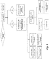
- the method comprises the deactivation of said activation button and, from that moment on, the following steps are carried out:
- step (b10) the electrical signals can be sent to solenoid valves so as to release the pneumatic air from the end release mechanism of the wheels.
- step (c) during step (c), and more particularly, after waiting for the predetermined time period ⁇ t, the electrical signals are sent to the solenoid valves in order to release the pneumatic air from the release mechanism of the rear axle locking system.
- the predetermined time period ⁇ t, established in step (c) is of the order of 15-45 seconds, and more particularly, 30 seconds.
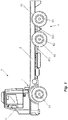
- Figure 1 schematically represents a road vehicle for transporting cargo or goods, such as a truck (V) comprising a tandem axle assembly (T) with a 6x4 type traction configuration.
- V a truck
- T tandem axle assembly
- the truck (V) comprises a cab (O) for the operator/conductor and under which a power train (F) transmission set is provided, such as a combustion engine associated with the gearbox, which are mounted on the chassis (C) which also supports a front axle (E1) and the set of tandem (T) traction axles formed by a first rear axle (E2) and a second rear axle (E3).
- a first cardan axle (EC1) extends from the gearbox to a first differential of the first rear axle (E2) and, from the differential of the first rear axle (E2), a second cardan axle (EC2) extends to the differential of the second rear axle (E3).
- the power is generally divided equally from the first and second differentials to the wheels (R2, R3) of the first and second rear axles (E2, E3).
- differentials transmit the power to the wheels of each axis in a usual way using a crown/pinion system and epicycloidal gears in a manner well known to those skilled in the art.
- Other details of the vehicle (V) are represented in a schematic way and dispense with further explanations, since they are well known in cargo transport vehicles known in the state of the art.
- patent applications BR 10 2016 029390-1 , BR 10 2016 029395-2 and BR 10 2016 029398-7 which refer to systems and mechanisms capable of selectively promoting the uncoupling of one of the drive axles, as well as the uncoupling of the wheels individually through, among a series of possible means, the pneumatic system of trucks (V).
- the aim of the present invention is precisely to monitor and safely control the operation of that rear axle and, more specifically, to disclose a method capable of controlling mechanisms and systems for coupling and uncoupling of axles and wheels, as well as the systems and mechanisms for listing the uncoupled axle.
- said method is intended for controlling the operation of the second rear axle (E3), in order to transform the 6x4 traction configuration to a 6x2 traction configuration, along with the raising of the uncoupled axle to obtain the economic benefits with fuel consumption and tire wear.
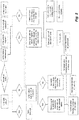
- the method for monitoring and controlling the operation of the rear axle of a set of combined drive axles begins with the operator/driver of the vehicle (V) by activating the actuation button which, according to an embodiment, is arranged inside the cab (O) of the vehicle (V). From this moment onwards, the method for controlling the operation of the vehicle axle basically comprises the following steps:
- the method for controlling the operation of the vehicle axle (V) is intended for trucks for cargo transport and whose tread limit with all its axles driven from the axle set is 43 tons, therefore, in said step (b8), the method checks whether the vehicle is loaded with up to 43 tons. If it is detected that it is not within the limit, return to step (b1), in which the raising of the axle is blocked.
- the method for controlling the operation of the vehicle axle (V) can emit electrical signals for the solenoid valves that supply pneumatic air to the wheel end release mechanism.
- the vehicle (V) is equipped with a wheel release system, as defined by patent documents BR 10 2016 029395-2 and BR 10 2016 029398-7 , cited merely by reference.
- step (b10) of the method for controlling the operation of the vehicle axle (V) it is possible that another electrical signal will be emitted for the solenoid valves feeding the release mechanism of the rear axle locking system, more specifically, the mechanism disposed in the differential of the first rear axle (E2), whose construction can be seen according to the teachings disclosed in patent document BR 10 2016 029390-1 , incorporated herein by reference.
- the present method for controlling the operation of the vehicle axle (V) is applied to the second rear axle (E3), and thus allowing the same vehicle to be able to work on a 6x4 or 6x2 traction configuration, providing greater flexibility to the driver/operator who can thus tow different types, models and carrying capacity.
- the method for controlling the operation of the vehicle axle basically comprises the following steps:
- the method for controlling the operation of the vehicle axle (V) can emit electrical signals to the solenoid valves responsible for the discharge of pneumatic air from the release mechanism of the wheel ends.
- the vehicle (V) is equipped with the wheel release system, as defined by patent documents BR 10 2016 029395-2 and BR 10 2016 029398-7 , cited by reference.
- step (c) in the mode of deactivation of the actuation button and, specifically in step (c), after waiting for the predetermined time period ⁇ t, it emits other electrical signals to the solenoid valves responsible for the discharge of pneumatic air from the release mechanism of the rear axle locking system, more particularly the mechanism arranged on the differential of the first rear axle (E2), the construction of which can be observed according to the teachings disclosed in patent document BR 10 2016 029390-1 , incorporated herein by reference.
- the predetermined time period ⁇ t, established in step (c) is of the order of 15-45 seconds, and more particularly, about 30 seconds.
- said vehicle (V) returns to its original traction configuration, such as 6x4, where said second rear axle (E3) is positioned in such a way as to place its wheels in contact with the ground, and the traction mechanisms are properly connected to transfer power to said axle.
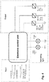
- Figure 4 shows a schematic representation through a block diagram, in which the main parameters that are monitored and controlled are identified by the present method for monitoring and controlling the rear axle operation of the combined set of drive axles of a vehicle. More particularly, on the one hand it is possible to verify the input parameters, which are engine operating signals, speed sensors, load sensors, indicators of the locking systems, as well as signals from the axle raising/lifting system and mechanism. On the other hand, the output signals responsible for activating the solenoid valves controlling the feeding and release of pneumatic air from the systems and mechanisms of wheel release and lock, and cardan axle release are checked.
- the input parameters which are engine operating signals, speed sensors, load sensors, indicators of the locking systems, as well as signals from the axle raising/lifting system and mechanism.
- the output signals responsible for activating the solenoid valves controlling the feeding and release of pneumatic air from the systems and mechanisms of wheel release and lock, and cardan axle release are checked.
- the method for monitoring and controlling the operation of the rear axle of a cargo transport vehicle with combined drive axles is capable of ensuring the proper functioning of the mechanisms and systems for locking and raising/lifting the axle and, more specifically, effectively control the safe conditions to allow the decoupling and raising of the axle only after identifying certain operating parameters which do not endanger the operator/driver and third parties.
Landscapes
- Engineering & Computer Science (AREA)
- Mechanical Engineering (AREA)
- Chemical & Material Sciences (AREA)
- Combustion & Propulsion (AREA)
- Transportation (AREA)
- Automation & Control Theory (AREA)
- Vehicle Body Suspensions (AREA)
- Arrangement And Driving Of Transmission Devices (AREA)
Abstract
Description
- The present invention generally refers to a method for controlling the safe operation of the rear axle of a set of combined axles driven by motor vehicles, such as road transport vehicles with 6x4, 8x4 or 10x4 type traction configurations, or tridem models formed by three drive axles.
- It is the general knowledge of those skilled in the art that motor vehicles and, more particularly, vehicles intended for road transport of freight, such as trucks, are usually driven through the rear axle assembly, which is connected by the so-called cardan axle to the drive axle formed primarily by the engine and gear. Said cardan axle is usually the connection between the output of the power assembly and the axle differential that transmits power to the wheels.
- For road freight vehicles that have two rear axles, vehicles can take on a 6x2, 6x4, 8x4, 10x4, or even a 6x6 and 8x8 configuration, as is the case with "off road", that is, a total number of contact points, two, four, six or even eight contact points have traction to provide vehicle movement. Particularly, in the case of tractor trucks, they usually have two rear axles, and can take on the 6x2 or 6x4 traction configuration, in which of the vehicle's six wheels, only two or four are driven, usually the two wheels of the first rear axle, or the four wheels of the two rear axles are driven.
- As those skilled in the art will appreciate, the use of at least two drive axles, as in the 6x4 configuration, is quite desirable for legislation, because there are countries, including Brazil, that restrict the movement of vehicles according to their load capacity and, for example, to carry a greater load limit the vehicle necessarily needs to rely on a 6x4 traction configuration. In addition, for application reasons, it is also desirable for vehicles to have a higher traction number, as with vehicles for off-road use, for example in sugarcane plantations or mining.
- However, when the vehicle is not loaded in order to obtain savings on fuel and tires, it is desirable that one of the axles is not used. If the traction configuration is, for example, of the type 6x2, one of the rear axles, the one not driven, may be suspended and, accordingly, fuel consumption may be reduced, as well as tire wear. This is possible according to a technical solution well known in the state of the art, in which an air bag is usually used to suspend the axle, thus taking advantage of the compressed air line existing in these types of vehicles.
- However, this type of solution is limited to the 6x2 traction configuration and cannot be used in vehicles with 6x4 or 8x4 traction configuration, for example, since no driven axle can be suspended as the power would be lost to the suspended axle. Therefore, for these reasons, many companies seek solutions that allow the coupling and uncoupling of the traction of at least one axle of a vehicle, particularly a cargo vehicle, such as trucks and tractor trucks.
- In this context, it is known that the state of the art contains some solutions whereby automatic or manual drive selection of one or more axles is permitted. An already known solution consists of engaging or decoupling the gear of the central differential sending power to the axle. This solution, however, cannot be applied to the 6x4 or 8x4 traction configurations, since no central differential is usually used, but traction is transmitted from one differential to another sequentially via the cardan axle.
- One solution that proved to be quite practical and functional is disclosed in patent application
BR10 2015 018592-8 PCT/BR2016/050182 - Thus, although the solution proposed in the state of the art is highly functional, there was still a need to provide a control method that ensures the proper activation of systems and mechanisms for coupling and raising axles, but mainly the safety of the vehicle, the driver and the highways. The present invention seeks to overcome this limitation of the state of the art.
- Given the scenario presented above, it is one of the objectives of this invention to provide a method for controlling the operation of the rear axle of a set of combined drive axles, particularly road freight vehicles with at least two drive axles, such as, for example, in the 6x4 and 8x4 traction configurations.
- More particularly, it is one of the objectives of this invention to provide a method for properly and effectively controlling the actuation of the systems and mechanisms for coupling traction and raising the rear axle of the combined drive axle set from a road cargo transport vehicle.
- Thus, in order to achieve the objectives and technical and functional effects mentioned above, as well as other advantages, the invention in question refers to a method for monitoring and controlling the operation of a rear axle of a vehicle, particularly those used for freight transport, being initially comprised by the activation of an actuation button that is usually inside the cab of said vehicle, based on which it has the following execution steps:
- a) check that the rear axle is locked:
- a1) if so, keep it locked;
- a2) if not, wait for the vehicle status to be checked:
- b) check the status of the vehicle - whether it is connected:
- b1) if not, it does not release the rear axle lifting;
- b2) if so, check the status of the vehicle - whether it is stationary:
- b3) if not, return to step (b1);
- b4) if so, check the status of the vehicle - whether it is unloaded:
- b5) if not, return to step (b1);
- b6) if so, check the status of the vehicle - whether it has sufficient air in the pneumatic system:
- b7) if not, return to step (b1)
- b8) if so, check that the vehicle is loaded with the capacity below the tread limit with all axles driven from the axle set:
- b9) if not, it does not release wheel end traction
- b10) if so, emit electrical signals to solenoid valves, respectively:
- to feed with pneumatic air the mechanism of release of the cardan axle;
- to feed with pneumatic air the raising/lifting mechanism of the rear axle.
- According to an embodiment of the present invention, during the step (b8) to check the weight of the vehicle with load, the tread limit with all the axles driven from the axle set should be 43 tons. Logically, such a limit may vary according to the laws of the country in which the vehicle travels. In this context, particularly according to the embodiment of the present invention, step (b8) analyzes whether the vehicle is loaded with up to 43 tons.
- According to another embodiment of the present invention, during said step (b10), it is possible to predict that electrical signals are emitted to solenoid valves to promote pneumatic air supply into the release mechanism of the wheel ends, and/or to the solenoid valves to provide pneumatic air supply of a release mechanism of the rear axle locking system, which is, according to one of the possible embodiments, arranged in the differential of the first rear axle of the vehicle's assembly axles.
- Additionally, according to another embodiment of the present invention, and more particularly to a complementary embodiment, the method comprises the deactivation of said activation button and, from that moment on, the following steps are carried out:
- (b) check the status of the vehicle - whether it is connected:
- b1) if not, it does not release the lowering of the rear axle;
- b2) if so, check the status of the vehicle - whether it is stationary:
- b3) if not, return to step (b1);
- b10) if so, emit electrical signals to solenoid valves to release pneumatic air from the raising/lifting mechanism of the rear axle;
- c) wait for a predetermined period of time Δt and send new electrical signals to the solenoid valves to release pneumatic air from the cardan axle release mechanism.
- Optionally, according to another embodiment of the present invention, in step (b10), the electrical signals can be sent to solenoid valves so as to release the pneumatic air from the end release mechanism of the wheels.
- Further, according to another embodiment of the method of the present invention, during step (c), and more particularly, after waiting for the predetermined time period Δt, the electrical signals are sent to the solenoid valves in order to release the pneumatic air from the release mechanism of the rear axle locking system.
- According to possible embodiments of the present invention, the predetermined time period Δt, established in step (c), is of the order of 15-45 seconds, and more particularly, 30 seconds.
- The characteristics, advantages and technical effects of the present invention, as indicated above, will be more appropriately understood by a person skilled in the art from the following detailed description, provided for illustration only, and non-restrictively, of preferred embodiments of the invention, which are based on the accompanying schematic drawings, wherein:
-
Figure 1 is a schematic side view of a cargo transportation vehicle, such as a truck, which has a 6x4 traction configuration, for example with a set of combined axle assembly of the tandem type; -
Figure 2 shows a schematic flowchart of the method for controlling the operation of the rear axle of a motor vehicle, according to the present invention, in activation condition; -
Figure 3 shows another schematic flowchart of the method for controlling the operation of the rear axle of a motor vehicle, according to the present invention, in deactivation condition; -
Figure 4 shows a schematic block diagram of the actuator components responsible for the method for controlling the operation of the rear axle of the motor vehicle, according to the present invention. - Initially, for the purpose of illustration and improved understanding of the present invention, as will be appreciated by those skilled in the art,
Figure 1 schematically represents a road vehicle for transporting cargo or goods, such as a truck (V) comprising a tandem axle assembly (T) with a 6x4 type traction configuration. - Thus, as indicated in
Figure 1 , the truck (V) comprises a cab (O) for the operator/conductor and under which a power train (F) transmission set is provided, such as a combustion engine associated with the gearbox, which are mounted on the chassis (C) which also supports a front axle (E1) and the set of tandem (T) traction axles formed by a first rear axle (E2) and a second rear axle (E3). A first cardan axle (EC1) extends from the gearbox to a first differential of the first rear axle (E2) and, from the differential of the first rear axle (E2), a second cardan axle (EC2) extends to the differential of the second rear axle (E3). Thus, the power is generally divided equally from the first and second differentials to the wheels (R2, R3) of the first and second rear axles (E2, E3). Furthermore, it is known that differentials transmit the power to the wheels of each axis in a usual way using a crown/pinion system and epicycloidal gears in a manner well known to those skilled in the art. Other details of the vehicle (V) are represented in a schematic way and dispense with further explanations, since they are well known in cargo transport vehicles known in the state of the art. - As indicated above, it is desirable for certain applications, such as vehicles without loads, that no power be transmitted from the differential of the first rear axle (E2) to the differential of the second rear axle (E3), causing the vehicle to assume a 6x2 traction configuration. With this 6x2 traction configuration, it is possible that the third axle (E3) - or second rear axle is raised in order to save fuel and tires. The form of raising of the second rear axle (E3) can be done by the usual known means, such as taking advantage of the pneumatic systems commonly present in vehicles for cargo transport, such as trucks (V). This type of decoupling of the traction of the second rear axle can be obtained through systems and mechanisms as defined in patent document
BR10 2015 018592-8 PCT/BR2016/050182 - Additionally, also prominently incorporated into the present by reference, patent applications
BR 10 2016 029390-1 BR 10 2016 029395-2 BR 10 2016 029398-7 - The aim of the present invention is precisely to monitor and safely control the operation of that rear axle and, more specifically, to disclose a method capable of controlling mechanisms and systems for coupling and uncoupling of axles and wheels, as well as the systems and mechanisms for listing the uncoupled axle. According to an embodiment of the present invention, said method is intended for controlling the operation of the second rear axle (E3), in order to transform the 6x4 traction configuration to a 6x2 traction configuration, along with the raising of the uncoupled axle to obtain the economic benefits with fuel consumption and tire wear.
- Naturally, the present detailed description of an embodiment of the invention is referred to as a 6x4 and 6x2 traction configuration, but of course the invention can be employed in any traction configuration which is desirable to activate or disable a traction axle, such as a traction configuration of 4x4 / 4x2 or 8x4 / 8x2, etc.
- Given the scenario summarized above, and as represented in the accompanying drawings, it can be said that the method for monitoring and controlling the operation of the rear axle of a set of combined drive axles, according to the present invention, begins with the operator/driver of the vehicle (V) by activating the actuation button which, according to an embodiment, is arranged inside the cab (O) of the vehicle (V). From this moment onwards, the method for controlling the operation of the vehicle axle basically comprises the following steps:
- a) check that the rear axle is locked:
- a1) if so, keep it locked;
- a2) if not, wait for the vehicle status to be checked (V):
- b) check the status of the vehicle - whether it is connected:
- b1) if not, it does not release the rear axle lifting;
- b2) if so, check the status of the vehicle - whether it is stationary:
- b3) if not, return to step (b1);
- b4) if so, check the status of the vehicle - whether it is discharged:
- b5) if not, return to step (b1);
- b6) if so, check the status of the vehicle - whether it has sufficient air in the pneumatic system:
- b7) If not, return to step (b1)
- b8) if so, check that the vehicle is loaded with the capacity below the tread limit with all axles driven from the axle set:
- b9) if not, it does not release wheel end traction
- b10) if so, issue electrical signals to solenoid valves, respectively:
- to feed with pneumatic air the mechanism of release of the cardan axle;
- to feed with pneumatic air the raising/lifting mechanism of the rear axle.
- Additionally, according to an optional embodiment of the present invention, the method for controlling the operation of the vehicle axle (V) is intended for trucks for cargo transport and whose tread limit with all its axles driven from the axle set is 43 tons, therefore, in said step (b8), the method checks whether the vehicle is loaded with up to 43 tons. If it is detected that it is not within the limit, return to step (b1), in which the raising of the axle is blocked.
- Also, according to said step (b10), according to another alternative embodiment of the present invention, the method for controlling the operation of the vehicle axle (V) can emit electrical signals for the solenoid valves that supply pneumatic air to the wheel end release mechanism. In this case, the vehicle (V) is equipped with a wheel release system, as defined by patent documents
BR 10 2016 029395-2 BR 10 2016 029398-7 - Optionally, further with respect to said step (b10) of the method for controlling the operation of the vehicle axle (V), it is possible that another electrical signal will be emitted for the solenoid valves feeding the release mechanism of the rear axle locking system, more specifically, the mechanism disposed in the differential of the first rear axle (E2), whose construction can be seen according to the teachings disclosed in patent document
BR 10 2016 029390-1 - According to an embodiment of the present invention, the present method for controlling the operation of the vehicle axle (V) is applied to the second rear axle (E3), and thus allowing the same vehicle to be able to work on a 6x4 or 6x2 traction configuration, providing greater flexibility to the driver/operator who can thus tow different types, models and carrying capacity.
- Continuing the method for monitoring and controlling the operation of the rear axle of the combined axle drive set, according to the present invention, when the driver/operator of the vehicle (V) wishes to disable the coupling and uncoupling systems and mechanisms of the axles and wheels, as well as the lifting systems and mechanisms of the uncoupled axle, it is necessary to disable the actuation button that is usually inside the cab (O) of the vehicle (V) and, from this point onwards, the method for controlling the operation of the vehicle axle basically comprises the following steps:
- b) check the status of the vehicle - whether it is connected:
- b1) if not, it does not release the lowering of the rear axle;
- b2) if so, check the status of the vehicle - whether it is stationary:
- b3) if not, return to step (b1);
- b10) if so, emit electrical signals to solenoid valves to release pneumatic air from the raising/lifting mechanism of the rear axle;
- c) wait for a predetermined period of time Δt and send new electrical signals to solenoid valves to release pneumatic air from the cardan axle release mechanism.
- Just as in the mode of activation of the actuation button, in the mode of deactivation of said button during the step (b10), according to an alternative embodiment of the present invention, the method for controlling the operation of the vehicle axle (V) can emit electrical signals to the solenoid valves responsible for the discharge of pneumatic air from the release mechanism of the wheel ends. In this case, the vehicle (V) is equipped with the wheel release system, as defined by patent documents
BR 10 2016 029395-2 BR 10 2016 029398-7 - Also, according to another optional embodiment of the present invention, in the mode of deactivation of the actuation button and, specifically in step (c), after waiting for the predetermined time period Δt, it emits other electrical signals to the solenoid valves responsible for the discharge of pneumatic air from the release mechanism of the rear axle locking system, more particularly the mechanism arranged on the differential of the first rear axle (E2), the construction of which can be observed according to the teachings disclosed in patent document
BR 10 2016 029390-1 - According to an embodiment of the present invention, the predetermined time period Δt, established in step (c), is of the order of 15-45 seconds, and more particularly, about 30 seconds.
- Thus, at the end, after completing the steps mentioned above, said vehicle (V) returns to its original traction configuration, such as 6x4, where said second rear axle (E3) is positioned in such a way as to place its wheels in contact with the ground, and the traction mechanisms are properly connected to transfer power to said axle.
- By way of illustration only,
Figure 4 shows a schematic representation through a block diagram, in which the main parameters that are monitored and controlled are identified by the present method for monitoring and controlling the rear axle operation of the combined set of drive axles of a vehicle. More particularly, on the one hand it is possible to verify the input parameters, which are engine operating signals, speed sensors, load sensors, indicators of the locking systems, as well as signals from the axle raising/lifting system and mechanism. On the other hand, the output signals responsible for activating the solenoid valves controlling the feeding and release of pneumatic air from the systems and mechanisms of wheel release and lock, and cardan axle release are checked. - In addition, as a way of interacting with the operator/driver of the vehicle (V), it is possible to have indicators on the functional state of the vehicle, according to the monitoring method conducted by this method of monitoring and controlling the operation of the rear axle of the vehicle, for example, light indicators such as lamps and signs, or even a computer interface capable of displaying graphic representations, etc.
- Thus, in view of the above, it is possible to note that the method for monitoring and controlling the operation of the rear axle of a cargo transport vehicle with combined drive axles, according to the present invention, is capable of ensuring the proper functioning of the mechanisms and systems for locking and raising/lifting the axle and, more specifically, effectively control the safe conditions to allow the decoupling and raising of the axle only after identifying certain operating parameters which do not endanger the operator/driver and third parties.
- Finally, considering the above, it is important to clarify that the purpose of this description is solely to present and define illustrations of preferred embodiments of the method for monitoring and controlling the real axle operation of a vehicle for cargo transport. Accordingly, as those skilled in the art will appreciate, various modifications and constructive and executive combinations of equivalent elements and steps are possible without straying from the scope of protection defined by the accompanying claims.
Claims (10)
- A METHOD FOR MONITORING AND CONTROLLING OPERATION OF THE REAR AXLE OF A VEHICLE, characterized by comprising the activation of an actuation button, from which the following execution steps are initiated:a) check that the rear axle is locked:a1) if so, keep locked;a2) if not, wait for the vehicle status to be checked (V):b) check the status of the vehicle - whether it is connected:b1) if not, it does not release the rear axle raising;b2) if so, check the status of the vehicle - whether it is stationary:b3) if not, return to step (b1);b4) if so, check the status of the vehicle - whether it is discharged:b5) if not, return to step (b1);b6) if so, check the status of the vehicle - whether it has sufficient air in the pneumatic system:b7) If not, return to step (b1)b8) if so, check that the vehicle is loaded with the capacity below the tread limit with all axles driven from the axle set:b9) if not, it does not release wheel end tractionb10) if so, emit electrical signals to solenoid valves, respectively:- to feed with pneumatic air the mechanism of release of the cardan axle;- to feed with pneumatic air the raising/lifting mechanism of the rear axle.
- The METHOD, according to claim 1, characterized by the fact that the vehicle capacity (V) within the tread limit with all its axles driven from the axle set is 43 tons.
- The METHOD, according to claim 1, characterized by the fact that in step (b8) is checked if the vehicle (V) is loaded with up to 43 tons.
- The METHOD, according to claim 1, characterized by the fact that in step (b10), electrical signals are sent to solenoid valves to power with pneumatic air a wheel end release mechanism.
- The METHOD, according to claim 1, characterized by the fact that in step (b10), electrical signals are sent to solenoid valves to power with pneumatic air a mechanism for releasing the rear axle locking system.
- The METHOD, according to claim 5, characterized by the fact that the said mechanism of release of the rear axle locking system is arranged in the differential of the first rear axle.
- The METHOD, according to claim 1, characterized by the fact that it comprises the deactivation of the said actuation button and, from that moment on, the following steps are performed:b) check the status of the vehicle - whether it is connected:b1) if not, it does not release the lowering of the rear axle;b2) if so, check the status of the vehicle - whether it is stationary:b3) if not, return to step (b1);b10) if so, emit electrical signals to solenoid valves to release pneumatic air from the raising/lifting mechanism of the rear axle;c) wait for a predetermined period of time Δt and send new electrical signals to solenoid valves to release pneumatic air from the cardan axle release mechanism.
- The METHOD, according to claim 7, characterized by the fact that in step (b10), electrical signals are sent to solenoid valves to release pneumatic air from the wheel end release mechanism.
- The METHOD, according to claim 7, characterized by the fact that in step (c), after waiting for the predetermined time period Δt, electrical signals are sent to solenoid valves to release pneumatic air from the rear axle locking system release mechanism.
- The METHOD, according to claim 7, characterized by the fact that the predetermined time period Δt, established in step (c), is of the order of 15-45 seconds, and more particularly, 30 seconds.
Applications Claiming Priority (2)
| Application Number | Priority Date | Filing Date | Title |
|---|---|---|---|
| BR102017025512-3A BR102017025512B1 (en) | 2017-11-28 | 2017-11-28 | Method for monitoring and controlling the operation of the rear axle of a vehicle |
| PCT/BR2018/050436 WO2019104404A1 (en) | 2017-11-28 | 2018-11-23 | Method for monitoring and controlling operation of the rear axle of a vehicle |
Publications (4)
| Publication Number | Publication Date |
|---|---|
| EP3736159A1 true EP3736159A1 (en) | 2020-11-11 |
| EP3736159A4 EP3736159A4 (en) | 2021-11-24 |
| EP3736159B1 EP3736159B1 (en) | 2025-08-13 |
| EP3736159C0 EP3736159C0 (en) | 2025-08-13 |
Family
ID=66663719
Family Applications (1)
| Application Number | Title | Priority Date | Filing Date |
|---|---|---|---|
| EP18884357.7A Active EP3736159B1 (en) | 2017-11-28 | 2018-11-23 | Method for monitoring and controlling operation of the rear axle of a vehicle |
Country Status (5)
| Country | Link |
|---|---|
| US (1) | US11247560B2 (en) |
| EP (1) | EP3736159B1 (en) |
| CN (1) | CN111587188B (en) |
| BR (1) | BR102017025512B1 (en) |
| WO (1) | WO2019104404A1 (en) |
Families Citing this family (1)
| Publication number | Priority date | Publication date | Assignee | Title |
|---|---|---|---|---|
| CN114148139B (en) * | 2021-11-09 | 2023-10-03 | 中国重汽集团济南动力有限公司 | A transaxle-boosting air suspension control system |
Family Cites Families (18)
| Publication number | Priority date | Publication date | Assignee | Title |
|---|---|---|---|---|
| IT1066939B (en) * | 1975-08-11 | 1985-03-12 | Eaton Corp | ENGINE AXLE ASSEMBLY WITH DETACHABLE REAR DRIVE AXLE |
| GB2066182B (en) | 1979-12-12 | 1983-05-25 | Scottorn Trailers Ltd | Power-driven vehicles and gear boxes for such vehicles |
| US5711389A (en) | 1995-11-03 | 1998-01-27 | Dana Corporation | Tandem rear drive axle assembly |
| DE102006060842A1 (en) * | 2006-12-22 | 2008-06-26 | Daimler Ag | Tandem axle with drivable lift axle |
| US20090166106A1 (en) * | 2007-12-27 | 2009-07-02 | Scott Daniel Batdorf | Vehicles Having Tandem Axle Assembly |
| EP2914452B1 (en) * | 2012-11-02 | 2019-02-27 | Dana Heavy Vehicle Systems Group, LLC | Hierarchical control system and method for a tandem axle drive system |
| EP2928718B1 (en) * | 2012-12-05 | 2020-08-19 | Mack Trucks, Inc. | Vehicle with multiple drive axle assembly with a raisable and lowerable rear drive axle, and method of neutralizing the rear drive axle and operating such a vehicle |
| US9656545B2 (en) * | 2013-09-10 | 2017-05-23 | Schaeffler Technologies AG & Co. KG | Tandem axle disconnect with synchronized overdrive |
| CA2938609C (en) * | 2014-03-04 | 2016-11-29 | Hendrickson Usa, L.L.C. | Parking brake interlock for automatic lift axle |
| GB2514910A (en) * | 2014-04-11 | 2014-12-10 | Daimler Ag | Tandem axle for a utility vehicle |
| GB2532739A (en) * | 2014-11-25 | 2016-06-01 | Daimler Ag | Tandem axle for a utility vehicle |
| EP3237246B1 (en) * | 2014-12-23 | 2020-03-04 | Volvo Truck Corporation | Method and device for tandem- or multiple-axle drive for a vehicle |
| BR102015018592A2 (en) | 2015-08-03 | 2017-02-07 | Cnh Ind Latin America Ltda | axle and vehicle coupling |
| GB2530877A (en) * | 2015-08-04 | 2016-04-06 | Daimler Ag | Drivetrain Arrangement for a Commercial Vehicle as well as Method for Operating such a Drivetrain Arrangement |
| DE102015014213A1 (en) * | 2015-11-04 | 2017-05-04 | Man Truck & Bus Ag | Commercial vehicle, in particular trucks, with at least one double axle unit |
| US20180051786A1 (en) * | 2016-08-22 | 2018-02-22 | Dana Heavy Vehicle Systems Group, Llc | Automated Differential Locking System |
| US9784355B1 (en) * | 2016-08-31 | 2017-10-10 | Dana Heavy Vehicle Systems Group, Llc | Axle disconnect and differential lock combination |
| BR102016029398B1 (en) | 2016-12-14 | 2021-03-16 | Cnh Industrial America Llc | wheel hub for combined axles and vehicle |
-
2017
- 2017-11-28 BR BR102017025512-3A patent/BR102017025512B1/en active IP Right Grant
-
2018
- 2018-11-23 WO PCT/BR2018/050436 patent/WO2019104404A1/en not_active Ceased
- 2018-11-23 EP EP18884357.7A patent/EP3736159B1/en active Active
- 2018-11-23 CN CN201880080858.XA patent/CN111587188B/en active Active
- 2018-11-23 US US16/767,981 patent/US11247560B2/en active Active
Also Published As
| Publication number | Publication date |
|---|---|
| EP3736159A4 (en) | 2021-11-24 |
| CN111587188B (en) | 2022-10-18 |
| EP3736159B1 (en) | 2025-08-13 |
| EP3736159C0 (en) | 2025-08-13 |
| WO2019104404A1 (en) | 2019-06-06 |
| US11247560B2 (en) | 2022-02-15 |
| BR102017025512A2 (en) | 2019-06-25 |
| CN111587188A (en) | 2020-08-25 |
| BR102017025512B1 (en) | 2022-02-22 |
| US20210188086A1 (en) | 2021-06-24 |
Similar Documents
| Publication | Publication Date | Title |
|---|---|---|
| CN106103147B (en) | Automatic air suspension system control system, vehicle travel control system and traction method | |
| JP5847189B2 (en) | Large transport vehicle for ISO containers | |
| US10099529B2 (en) | Automatically deploying lift axle control system | |
| JP7240656B2 (en) | Lifting platform truck | |
| JP3361275B2 (en) | Camping self-propelled trailer dump | |
| CN101456356A (en) | 4-wheel driven articulated tractor trucks | |
| US9821780B2 (en) | Automated differential lock | |
| US9180845B2 (en) | Passenger car transport | |
| EP3736159B1 (en) | Method for monitoring and controlling operation of the rear axle of a vehicle | |
| ITMI20112109A1 (en) | TRAINED AND SELF-ARTICLE TRAILER PROVIDED WITH THIS TRAILER | |
| US20200086685A1 (en) | Motorized Axle and Vehicle Equipped with Such an Axle | |
| CN201357752Y (en) | 4 wheel driven bowing-type tractor transportation vehicle | |
| CN217227297U (en) | Variable chassis system of commercial car drive pattern | |
| CN104699103B (en) | The four vehicle load sharing intelligent tow truck systems for narrow space | |
| AU2025204879A1 (en) | Retrieval Trailer | |
| US12473021B2 (en) | Control device and method for controlling a tag axle steering system | |
| CN203543675U (en) | Automobile axle with separation device | |
| WO2020051621A1 (en) | A reconfigurable trailer | |
| US7441781B2 (en) | Lift system for raising the rear of a truck | |
| CN205395875U (en) | A control system for tipper safety lifts | |
| US2072728A (en) | Trailer hitch | |
| US4826195A (en) | Auxiliary towing apparatus for tractor trucks and the like | |
| CN210234647U (en) | Axle hydraulic drive device | |
| WO2026025152A1 (en) | A control unit for a mining vehicle | |
| CN203032768U (en) | Traction chassis of full trailer |
Legal Events
| Date | Code | Title | Description |
|---|---|---|---|
| STAA | Information on the status of an ep patent application or granted ep patent |
Free format text: STATUS: THE INTERNATIONAL PUBLICATION HAS BEEN MADE |
|
| PUAI | Public reference made under article 153(3) epc to a published international application that has entered the european phase |
Free format text: ORIGINAL CODE: 0009012 |
|
| STAA | Information on the status of an ep patent application or granted ep patent |
Free format text: STATUS: REQUEST FOR EXAMINATION WAS MADE |
|
| 17P | Request for examination filed |
Effective date: 20200629 |
|
| AK | Designated contracting states |
Kind code of ref document: A1 Designated state(s): AL AT BE BG CH CY CZ DE DK EE ES FI FR GB GR HR HU IE IS IT LI LT LU LV MC MK MT NL NO PL PT RO RS SE SI SK SM TR |
|
| AX | Request for extension of the european patent |
Extension state: BA ME |
|
| DAV | Request for validation of the european patent (deleted) | ||
| DAX | Request for extension of the european patent (deleted) | ||
| RAP1 | Party data changed (applicant data changed or rights of an application transferred) |
Owner name: IVECO S.P.A. |
|
| A4 | Supplementary search report drawn up and despatched |
Effective date: 20211022 |
|
| RIC1 | Information provided on ipc code assigned before grant |
Ipc: B60G 17/005 20060101ALI20211018BHEP Ipc: B60G 17/017 20060101ALI20211018BHEP Ipc: B62D 61/12 20060101ALI20211018BHEP Ipc: B60G 5/00 20060101ALI20211018BHEP Ipc: B60G 17/0195 20060101ALI20211018BHEP Ipc: B60K 23/00 20060101ALI20211018BHEP Ipc: B60K 23/08 20060101ALI20211018BHEP Ipc: B60K 17/00 20060101ALI20211018BHEP Ipc: B60K 17/36 20060101AFI20211018BHEP |
|
| STAA | Information on the status of an ep patent application or granted ep patent |
Free format text: STATUS: EXAMINATION IS IN PROGRESS |
|
| 17Q | First examination report despatched |
Effective date: 20220826 |
|
| GRAJ | Information related to disapproval of communication of intention to grant by the applicant or resumption of examination proceedings by the epo deleted |
Free format text: ORIGINAL CODE: EPIDOSDIGR1 |
|
| GRAP | Despatch of communication of intention to grant a patent |
Free format text: ORIGINAL CODE: EPIDOSNIGR1 |
|
| RIC1 | Information provided on ipc code assigned before grant |
Ipc: B60K 17/00 20060101ALI20250128BHEP Ipc: B60K 23/08 20060101ALI20250128BHEP Ipc: B60K 23/00 20060101ALI20250128BHEP Ipc: B60G 17/0195 20060101ALI20250128BHEP Ipc: B60G 5/00 20060101ALI20250128BHEP Ipc: B62D 61/12 20060101ALI20250128BHEP Ipc: B60G 17/017 20060101ALI20250128BHEP Ipc: B60G 17/005 20060101ALI20250128BHEP Ipc: B60K 17/35 20060101ALI20250128BHEP Ipc: B60K 17/36 20060101AFI20250128BHEP |
|
| GRAP | Despatch of communication of intention to grant a patent |
Free format text: ORIGINAL CODE: EPIDOSNIGR1 |
|
| STAA | Information on the status of an ep patent application or granted ep patent |
Free format text: STATUS: GRANT OF PATENT IS INTENDED |
|
| INTG | Intention to grant announced |
Effective date: 20250320 |
|
| GRAS | Grant fee paid |
Free format text: ORIGINAL CODE: EPIDOSNIGR3 |
|
| GRAA | (expected) grant |
Free format text: ORIGINAL CODE: 0009210 |
|
| STAA | Information on the status of an ep patent application or granted ep patent |
Free format text: STATUS: THE PATENT HAS BEEN GRANTED |
|
| AK | Designated contracting states |
Kind code of ref document: B1 Designated state(s): AL AT BE BG CH CY CZ DE DK EE ES FI FR GB GR HR HU IE IS IT LI LT LU LV MC MK MT NL NO PL PT RO RS SE SI SK SM TR |
|
| REG | Reference to a national code |
Ref country code: GB Ref legal event code: FG4D |
|
| REG | Reference to a national code |
Ref country code: CH Ref legal event code: EP |
|
| REG | Reference to a national code |
Ref country code: DE Ref legal event code: R096 Ref document number: 602018084639 Country of ref document: DE |
|
| REG | Reference to a national code |
Ref country code: IE Ref legal event code: FG4D |
|
| U01 | Request for unitary effect filed |
Effective date: 20250813 |
|
| U07 | Unitary effect registered |
Designated state(s): AT BE BG DE DK EE FI FR IT LT LU LV MT NL PT RO SE SI Effective date: 20250821 |
|
| U20 | Renewal fee for the european patent with unitary effect paid |
Year of fee payment: 8 Effective date: 20251003 |
|
| PG25 | Lapsed in a contracting state [announced via postgrant information from national office to epo] |
Ref country code: IS Free format text: LAPSE BECAUSE OF FAILURE TO SUBMIT A TRANSLATION OF THE DESCRIPTION OR TO PAY THE FEE WITHIN THE PRESCRIBED TIME-LIMIT Effective date: 20251213 |
|
| PG25 | Lapsed in a contracting state [announced via postgrant information from national office to epo] |
Ref country code: NO Free format text: LAPSE BECAUSE OF FAILURE TO SUBMIT A TRANSLATION OF THE DESCRIPTION OR TO PAY THE FEE WITHIN THE PRESCRIBED TIME-LIMIT Effective date: 20251113 |
|
| PG25 | Lapsed in a contracting state [announced via postgrant information from national office to epo] |
Ref country code: HR Free format text: LAPSE BECAUSE OF FAILURE TO SUBMIT A TRANSLATION OF THE DESCRIPTION OR TO PAY THE FEE WITHIN THE PRESCRIBED TIME-LIMIT Effective date: 20250813 |
|
| PG25 | Lapsed in a contracting state [announced via postgrant information from national office to epo] |
Ref country code: GR Free format text: LAPSE BECAUSE OF FAILURE TO SUBMIT A TRANSLATION OF THE DESCRIPTION OR TO PAY THE FEE WITHIN THE PRESCRIBED TIME-LIMIT Effective date: 20251114 |
|
| PG25 | Lapsed in a contracting state [announced via postgrant information from national office to epo] |
Ref country code: PL Free format text: LAPSE BECAUSE OF FAILURE TO SUBMIT A TRANSLATION OF THE DESCRIPTION OR TO PAY THE FEE WITHIN THE PRESCRIBED TIME-LIMIT Effective date: 20250813 |
|
| PG25 | Lapsed in a contracting state [announced via postgrant information from national office to epo] |
Ref country code: RS Free format text: LAPSE BECAUSE OF FAILURE TO SUBMIT A TRANSLATION OF THE DESCRIPTION OR TO PAY THE FEE WITHIN THE PRESCRIBED TIME-LIMIT Effective date: 20251113 |
|
| PG25 | Lapsed in a contracting state [announced via postgrant information from national office to epo] |
Ref country code: ES Free format text: LAPSE BECAUSE OF FAILURE TO SUBMIT A TRANSLATION OF THE DESCRIPTION OR TO PAY THE FEE WITHIN THE PRESCRIBED TIME-LIMIT Effective date: 20250813 |
|
| PG25 | Lapsed in a contracting state [announced via postgrant information from national office to epo] |
Ref country code: SM Free format text: LAPSE BECAUSE OF FAILURE TO SUBMIT A TRANSLATION OF THE DESCRIPTION OR TO PAY THE FEE WITHIN THE PRESCRIBED TIME-LIMIT Effective date: 20250813 |
|
| PG25 | Lapsed in a contracting state [announced via postgrant information from national office to epo] |
Ref country code: CZ Free format text: LAPSE BECAUSE OF FAILURE TO SUBMIT A TRANSLATION OF THE DESCRIPTION OR TO PAY THE FEE WITHIN THE PRESCRIBED TIME-LIMIT Effective date: 20250813 |
|
| PG25 | Lapsed in a contracting state [announced via postgrant information from national office to epo] |
Ref country code: SK Free format text: LAPSE BECAUSE OF FAILURE TO SUBMIT A TRANSLATION OF THE DESCRIPTION OR TO PAY THE FEE WITHIN THE PRESCRIBED TIME-LIMIT Effective date: 20250813 |