EP3736050A1 - Vorrichtung und verfahren zum aufbringen flüssiger medien auf eine substratoberfläche - Google Patents
Vorrichtung und verfahren zum aufbringen flüssiger medien auf eine substratoberfläche Download PDFInfo
- Publication number
- EP3736050A1 EP3736050A1 EP20173799.6A EP20173799A EP3736050A1 EP 3736050 A1 EP3736050 A1 EP 3736050A1 EP 20173799 A EP20173799 A EP 20173799A EP 3736050 A1 EP3736050 A1 EP 3736050A1
- Authority
- EP
- European Patent Office
- Prior art keywords
- approximately
- fluid guide
- fluid
- substrate surface
- guide device
- Prior art date
- Legal status (The legal status is an assumption and is not a legal conclusion. Google has not performed a legal analysis and makes no representation as to the accuracy of the status listed.)
- Granted
Links
Images




Classifications
-
- H—ELECTRICITY
- H10—SEMICONDUCTOR DEVICES; ELECTRIC SOLID-STATE DEVICES NOT OTHERWISE PROVIDED FOR
- H10P—GENERIC PROCESSES OR APPARATUS FOR THE MANUFACTURE OR TREATMENT OF DEVICES COVERED BY CLASS H10
- H10P72/00—Handling or holding of wafers, substrates or devices during manufacture or treatment thereof
- H10P72/04—Apparatus for manufacture or treatment
- H10P72/0448—Apparatus for applying a liquid, a resin, an ink or the like
-
- B—PERFORMING OPERATIONS; TRANSPORTING
- B05—SPRAYING OR ATOMISING IN GENERAL; APPLYING FLUENT MATERIALS TO SURFACES, IN GENERAL
- B05C—APPARATUS FOR APPLYING FLUENT MATERIALS TO SURFACES, IN GENERAL
- B05C11/00—Component parts, details or accessories not specifically provided for in groups B05C1/00 - B05C9/00
- B05C11/10—Storage, supply or control of liquid or other fluent material; Recovery of excess liquid or other fluent material
- B05C11/1002—Means for controlling supply, i.e. flow or pressure, of liquid or other fluent material to the applying apparatus, e.g. valves
- B05C11/1007—Means for controlling supply, i.e. flow or pressure, of liquid or other fluent material to the applying apparatus, e.g. valves responsive to condition of liquid or other fluent material
- B05C11/1013—Means for controlling supply, i.e. flow or pressure, of liquid or other fluent material to the applying apparatus, e.g. valves responsive to condition of liquid or other fluent material responsive to flow or pressure of liquid or other fluent material
-
- B—PERFORMING OPERATIONS; TRANSPORTING
- B05—SPRAYING OR ATOMISING IN GENERAL; APPLYING FLUENT MATERIALS TO SURFACES, IN GENERAL
- B05C—APPARATUS FOR APPLYING FLUENT MATERIALS TO SURFACES, IN GENERAL
- B05C11/00—Component parts, details or accessories not specifically provided for in groups B05C1/00 - B05C9/00
- B05C11/10—Storage, supply or control of liquid or other fluent material; Recovery of excess liquid or other fluent material
- B05C11/1044—Apparatus or installations for supplying liquid or other fluent material to several applying apparatus or several dispensing outlets, e.g. to several extrusion nozzles
-
- B—PERFORMING OPERATIONS; TRANSPORTING
- B05—SPRAYING OR ATOMISING IN GENERAL; APPLYING FLUENT MATERIALS TO SURFACES, IN GENERAL
- B05C—APPARATUS FOR APPLYING FLUENT MATERIALS TO SURFACES, IN GENERAL
- B05C5/00—Apparatus in which liquid or other fluent material is projected, poured or allowed to flow on to the surface of the work
- B05C5/02—Apparatus in which liquid or other fluent material is projected, poured or allowed to flow on to the surface of the work the liquid or other fluent material being discharged through an outlet orifice by pressure, e.g. from an outlet device in contact or almost in contact, with the work
- B05C5/0208—Apparatus in which liquid or other fluent material is projected, poured or allowed to flow on to the surface of the work the liquid or other fluent material being discharged through an outlet orifice by pressure, e.g. from an outlet device in contact or almost in contact, with the work for applying liquid or other fluent material to separate articles
- B05C5/0212—Apparatus in which liquid or other fluent material is projected, poured or allowed to flow on to the surface of the work the liquid or other fluent material being discharged through an outlet orifice by pressure, e.g. from an outlet device in contact or almost in contact, with the work for applying liquid or other fluent material to separate articles only at particular parts of the articles
- B05C5/0216—Apparatus in which liquid or other fluent material is projected, poured or allowed to flow on to the surface of the work the liquid or other fluent material being discharged through an outlet orifice by pressure, e.g. from an outlet device in contact or almost in contact, with the work for applying liquid or other fluent material to separate articles only at particular parts of the articles by relative movement of article and outlet according to a predetermined path
- B05C5/022—Apparatus in which liquid or other fluent material is projected, poured or allowed to flow on to the surface of the work the liquid or other fluent material being discharged through an outlet orifice by pressure, e.g. from an outlet device in contact or almost in contact, with the work for applying liquid or other fluent material to separate articles only at particular parts of the articles by relative movement of article and outlet according to a predetermined path the outlet being fixed during operation
-
- B—PERFORMING OPERATIONS; TRANSPORTING
- B05—SPRAYING OR ATOMISING IN GENERAL; APPLYING FLUENT MATERIALS TO SURFACES, IN GENERAL
- B05C—APPARATUS FOR APPLYING FLUENT MATERIALS TO SURFACES, IN GENERAL
- B05C5/00—Apparatus in which liquid or other fluent material is projected, poured or allowed to flow on to the surface of the work
- B05C5/02—Apparatus in which liquid or other fluent material is projected, poured or allowed to flow on to the surface of the work the liquid or other fluent material being discharged through an outlet orifice by pressure, e.g. from an outlet device in contact or almost in contact, with the work
- B05C5/027—Coating heads with several outlets, e.g. aligned transversally to the moving direction of a web to be coated
-
- H—ELECTRICITY
- H10—SEMICONDUCTOR DEVICES; ELECTRIC SOLID-STATE DEVICES NOT OTHERWISE PROVIDED FOR
- H10F—INORGANIC SEMICONDUCTOR DEVICES SENSITIVE TO INFRARED RADIATION, LIGHT, ELECTROMAGNETIC RADIATION OF SHORTER WAVELENGTH OR CORPUSCULAR RADIATION
- H10F77/00—Constructional details of devices covered by this subclass
- H10F77/20—Electrodes
- H10F77/206—Electrodes for devices having potential barriers
- H10F77/211—Electrodes for devices having potential barriers for photovoltaic cells
-
- B—PERFORMING OPERATIONS; TRANSPORTING
- B05—SPRAYING OR ATOMISING IN GENERAL; APPLYING FLUENT MATERIALS TO SURFACES, IN GENERAL
- B05C—APPARATUS FOR APPLYING FLUENT MATERIALS TO SURFACES, IN GENERAL
- B05C11/00—Component parts, details or accessories not specifically provided for in groups B05C1/00 - B05C9/00
- B05C11/02—Apparatus for spreading or distributing liquids or other fluent materials already applied to a surface ; Controlling means therefor; Control of the thickness of a coating by spreading or distributing liquids or other fluent materials already applied to the coated surface
- B05C11/06—Apparatus for spreading or distributing liquids or other fluent materials already applied to a surface ; Controlling means therefor; Control of the thickness of a coating by spreading or distributing liquids or other fluent materials already applied to the coated surface with a blast of gas or vapour
Definitions
- the invention relates to a device for applying liquid media to a substrate surface, comprising a fluid guide device and at least one fluid delivery device and at least one feed device for generating a relative movement at least between the substrate surface and part of the fluid guide device.
- the invention also relates to a method for applying liquid media to a substrate surface, in which the liquid medium is conveyed with at least one fluid conveying device to at least one fluid conveying device, with at least one advancing device generating a relative movement at least between the substrate surface and part of the fluid conveying device.
- Devices and methods of this type can be used for producing conductor tracks or electrical contacts on semiconductor substrates, for locally applying an etchant or for generative manufacturing processes.
- the invention is therefore based on the object of producing structures with small dimensions with high reliability and short processing times on substrate surfaces.
- a device for applying liquid media which contains a fluid guide device.
- the fluid guide device can be a capillary made of glass or quartz or plastic, or it can contain such a capillary.
- the capillary can be flexible at least in part, so that it can be placed on the substrate surface when the device is in operation.
- the fluid guide device can contain, in a manner known per se, a hose system or a pipe system for supplying the liquid medium. According to the invention, it is therefore proposed to apply a liquid medium to a substrate surface through one or more capillaries. The open end of the capillary intended for the exit of the liquid medium is guided in a sliding manner on the substrate surface.
- the outer diameter of the capillary can be less than about 25 ⁇ m or about 15 ⁇ m or about 10 ⁇ m or about 7 ⁇ m in at least one section at the end facing the substrate surface or at the opening in contact with the substrate surface. According to the invention, it was recognized that the outer diameter of the capillary corresponds to the structure width of the strand of the deposited on the substrate surface influenced liquid medium, so that small structures can also be produced with the disclosed capillaries.
- the outer diameter of the capillary can have an outer diameter in at least a partial section at the end facing the substrate surface or at the opening in contact with the substrate surface, which is greater than about 1 ⁇ m or greater than about 3 ⁇ m or greater than about 5 ⁇ m.
- the capillary can have a first longitudinal section which is angled or bent relative to a second longitudinal section of the capillary.
- the first and second longitudinal sections can enclose an angle of about 170 ° to about 100 ° or from about 160 ° to about 110 ° or from about 150 ° to about 120 °.
- the capillary can be straight, i. the first and the second longitudinal section enclose an angle of approximately 180 °.
- the capillary can be installed inclined in the device so that it forms an angle of about 80 ° to about 10 ° or from about 70 ° to about 20 ° or from about 30 ° to about 45 ° or at least when the device is in operation from about 20 ° to about 10 ° to the normal vector of the substrate surface. This reduces the damage to the substrate surface in contact with the capillary and / or can reduce the risk of the capillary breaking.
- At least one fluid conveying device is used to supply the liquid medium into the fluid conveying device, which conveys the liquid medium at constant pressure and / or constant flow rate into the fluid conveying device and then onto the substrate surface.
- the substrate surface with the liquid medium there is no full-area coating of the substrate surface with the liquid medium, but rather the application of a partial coating or a coating which only covers a partial area of the substrate surface.
- the coated partial areas can form one or more straight or curved lines. These can run next to one another at a constant distance and / or intersect with other lines.
- a single line or partial area can have a width of approximately 50 ⁇ m to approximately 2 ⁇ m or from approximately 30 ⁇ m to approximately 2 ⁇ m or approximately 15 ⁇ m to approximately 4 ⁇ m.
- the partial area coated with the liquid medium can be circular or point-shaped or have a plurality of individual points along a line.
- the device according to the invention has at least one feed device which is used to generate a relative movement between at least part of the fluid guide device and the substrate surface.
- the feed device can contain or consist of a linear drive.
- the device for applying liquid media can generate dot sequences or continuous or broken lines.
- a plurality of parallel lines can be generated by a plurality of fluid guide devices arranged in parallel.
- the feed device can contain or consist of an xy table, so that the substrate can be moved in two directions under a static fluid guide device.
- the movement in two axes allows the application of a plurality of parallel lines with a fluid guide device or the generation of curved or grid-shaped lines.
- the feed device can also enable rotation about at least one axis, for example about the normal direction of the plane spanned by the xy table.
- rotation about at least one axis for example about the normal direction of the plane spanned by the xy table.
- the substrate can also be stored in a stationary manner if the feed device is set up to move the entire fluid guide device or at least a part of the fluid guide device.
- the feed device is set up to enable a relative movement between the substrate and the fluid guide device or a part of the fluid guide device within the plane defined by the substrate.
- the substrate can be a semiconductor material which is provided with electrical contacts.
- the semiconductor substrate can be a photovoltaic cell which is provided with a front-side or a rear-side contact.
- the substrate can contain a metal, an alloy or a semiconductor material, to which locally etching media are applied in order in this way to produce structures in the substrate surface.
- the liquid medium can be an explosive medium, a pyrophoric medium and / or a medium with low vapor pressure.
- the device according to the invention enables, for example, solar cell production using silanes, in particular monosilane.
- the invention enables the production of compound semiconductors, for example using monophosphane or other precursors that are difficult to handle.
- the liquid medium can contain nanoparticles, for example particles made of a metal or an alloy, which form electrically conductive structures after evaporation of a liquid solvent and an optional sintering or tempering step.
- the liquid medium can contain living cells, which can be assembled into larger organisms and / or organs in a 3D printing process. Alternatively, living cells can be placed on a slide or a lab-on-chip to carry out biological experiments with high accuracy.
- the device can further contain at least one drive device for changing the distance between the substrate surface and part of a second longitudinal section of the fluid guide device.
- the drive device is provided on the one hand to avoid damage to the capillary of the fluid guide device and on the other hand to avoid damage to the substrate surface by the fluid guide device being placed hard on.
- a drive device is provided which can set the distance with high accuracy and high control speed. This makes it possible that the longitudinal section of the fluid guide device which is in contact with the substrate surface, e.g. the end of a glass capillary is either guided at a small distance above the substrate surface or the glass capillary slides in contact with the substrate surface with a low pressing force, so that damage to the substrate surface and the capillary is avoided.
- maintaining a constant distance or a constant contact pressure serves to generate a line of constant width.
- a device for distance detection may be present, which the Determines the distance between the substrate surface and part of a second longitudinal section of the fluid guide device.
- an optical distance measurement can take place, for example by image processing of a microscope image or by laser interference.
- the contact pressure between the substrate surface and the fluid guide device can be used as a measure of the distance between the two components. The actual value of the distance recorded in this way can be compared with a predeterminable setpoint value and used to control the drive device.
- the drive device can contain or consist of at least one piezo actuator.
- a drive device enables rapid adjustment, so that the distance between the fluid guide device and the substrate surface can be controlled or regulated even at a high feed rate without applying inadmissibly high forces to the substrate surface, thereby damaging the fluid guide device or the substrate surface.
- the drive device can enable a travel range from approximately 100 ⁇ m to approximately 300 ⁇ m or from approximately 150 ⁇ m to approximately 250 ⁇ m or from approximately 180 ⁇ m to approximately 220 ⁇ m. This travel is sufficient to prevent undesired collisions of the fluid conveying device with the substrate surface, so that damage to the substrate or the fluid conveying device is avoided.
- the drive device can be set up to travel through the travel range with a frequency of approximately 200 Hz to approximately 2000 Hz or from approximately 500 Hz to approximately 1500 Hz or from approximately 800 Hz to approximately 1200 Hz.
- a high adjustment speed of the Drive device enables the compensation of unevenness on the substrate surface and / or the placement and lifting of the fluid guide device from the substrate surface even at high feed speeds of the feed device, so that the processing speed can be increased when applying liquid media.
- the fluid guide device can have at least one second longitudinal section which has an inner diameter of approximately 0.5 ⁇ m to approximately 10 ⁇ m or from approximately 2 ⁇ m to approximately 8 ⁇ m or from approximately 4 ⁇ m to approximately 6 ⁇ m.
- This second longitudinal section is set up and intended to form the distal end of the fluid guide device and thus to define that opening through which the liquid medium is applied to the substrate surface. Since the diameter is thus about a factor of 6 to 10 smaller than with known dispensing needles, the structures produced with the device according to the invention on the substrate surface can also be a factor of 5 to 10 smaller.
- the fluid delivery device can contain or consist of an eccentric screw pump or a piston pump or a syringe pump.
- These fluid conveying devices can be precisely regulated in terms of flow rate and pressure, so that the conveying quantity of the liquid medium can be precisely controlled by the fluid conveying device and, as a result, the structures produced can also be precisely controlled in terms of width and / or longitudinal extent.
- the fluid delivery device can be configured to deliver the liquid medium at a pressure of about 100 mbar to about 500 mbar or from about 150 mbar to about 300 mbar or from about 500 mbar to about 5000 mbar or from about 1000 mbar to approximately 2000 mbar from about 0 mbar to about 100 mbar.
- the pressure ranges mentioned make it possible on the one hand to also reliably convey liquid media, which contain nanoparticles, for example, and thus have a higher viscosity, through a thin fluid guide device.
- the pressures are low enough not to destroy, for example, living cells when applied to the substrate surface.
- the feed device can be configured to operate at a feed rate of about 100 mm / s to about 1000 mm / s or from about 300 mm / s to about 900 mm / s or from about 500 mm / s to about 800 mm / s to be operated.
- This allows a rapid production of straight structures in particular with the device according to the invention, so that mass-produced articles such as solar cells can be processed with a plurality of fluid guide devices with a throughput of up to 23,000 wafers per hour, especially with parallel application of the front side contacts.
- the device furthermore contains a valve for regulating the volume flow of the liquid medium emerging from the fluid guide device.
- a valve for regulating the volume flow of the liquid medium emerging from the fluid guide device.
- the device can also contain an inert gas supply device.
- sensitive media for example substances that tend to self-ignite or oxidize quickly in air, can also be processed.
- the inert gas feed device can have a feed line which concentrically surrounds the fluid guide device.
- the inert gas supply device can have an optional discharge line which concentrically surrounds the supply line. This makes it possible not only to supply an inert gas, but also to suck out the inert gas and / or components of the liquid medium via the discharge line, so that the device can also be suitable for processing toxic media.
- the inert gas supply device can contain a heating device with which the inert gas supplied can be heated.
- the liquid medium can have a viscosity from about 5 mPas to about 200 mPas or from about 5 mPas to about 20 mPas. These media can also be conveyed through fluid guide devices with a small inner diameter.
- the liquid medium can contain metallic nanoparticles with a concentration of about 2% by volume to about 10% by volume or from about 2% by volume to about 6% by volume or from about 3% by volume. % to about 5% by volume.
- the liquid medium can be a conductive inkjet ink, with which conductive Structures such as front-side contacts can be applied to photovoltaic cells in an inkjet printing process.
- the liquid medium is continuously conveyed and not applied in the form of individual drops.
- the structures produced according to the invention can be significantly finer and, for example, have widths transverse to the feed rate of about 2 ⁇ m to about 10 ⁇ m.
- the continuous flow of material also prevents inadmissibly high contact resistances from developing between individual droplets, so that the conductive contacts produced according to the invention can have an increased conductivity or a low ohmic resistance.
- a relative movement takes place between the fluid guide device and the substrate surface. This prevents the substrate surface and / or the fluid guide device from being damaged by a hard impact of the fluid guide device on the substrate.
- Figure 1 a plurality of fluid guide devices arranged in parallel on a substrate 2 and Figure 2 shows a section of a single fluid guide device in operation.
- the figures show a substrate 2 with a substrate surface 21.
- the substrate 2 can for example be a semiconductor material, such as a photovoltaic cell, which is to be provided with a front-side contact.
- the device according to the invention is provided with a plurality of Fluid guide devices 3 used.
- five fluid guide devices arranged in parallel are provided.
- the number of fluid guide devices can also be larger or smaller, for example between one and about fifty. As a result, a plurality of parallel lines can be applied to the substrate 2 at the same time, which reduces the processing time.
- the fluid guide device 3 has at least one first longitudinal section 31, which has a comparatively large diameter and thus has a higher mechanical stability, and a second longitudinal section 32, which has lower mechanical stability due to its smaller diameter.
- the second longitudinal section 32 is arranged downstream of the first longitudinal section 31.
- the second longitudinal section 32 can, at least in sections, have an inner diameter of approximately 0.5 ⁇ m to approximately 10 ⁇ m or from approximately 2 ⁇ m to approximately 8 ⁇ m or from approximately 4 ⁇ m to approximately 6 ⁇ m.
- the outer diameter is increased by the wall thickness of the second longitudinal section, which is between approximately 1 ⁇ m and approximately 4 ⁇ m.
- the outer diameter of the second longitudinal section 32 defines the width of the structures produced.
- This part of the fluid guide device can be formed from a glass capillary or contain a glass capillary.
- the second longitudinal section 32 is mechanically in contact with the substrate surface 21, as a result of which the fluid guide device 3 can bend at its distal end as a function of the distance and contact pressure.
- a relative movement 255 is generated between the fluid guide device 3 and the substrate 2 by a feed device (not shown).
- the liquid medium 6 With simultaneous conveyance of the liquid medium 6 by the fluid conveying device the liquid medium 6 is deposited in a line on the substrate surface 21.
- this is a conductively filled ink
- the front-side contact produced in this way can be mechanically stabilized and / or electrically activated by subsequent annealing.
- the flow of liquid starts automatically at constant pressure if the surface energy of the substrate surface 21 is higher than the surface energy of the surface of the second longitudinal section 32 of the fluid conveying device 3.
- the liquid medium can be an aqueous medium Be solution or suspension if the substrate surface 21 is hydrophilic and at least the second longitudinal section 32 of the fluid conveying device 3 is hydrophobic.
- the current applied to the substrate can be controlled or regulated solely by the distance or the contact pressure of the second longitudinal section 32 of the fluid delivery device 3 on the substrate surface 21.
- the respective surface energies can be selected accordingly.
- Figure 3 shows a first embodiment of the device according to the invention.
- a substrate 2 is shown with a substrate surface 21 to which a liquid medium 6 is to be applied.
- the fluid guide device 3 is available, which is in contact with the substrate surface 21 with its second longitudinal section 32.
- the fluid guide device 3 can in some embodiments of the invention are made of glass or plastic and is mechanically flexible due to its small outer diameter, so that the in Figure 3 and Figure 2 The shape shown forms due to the relative movement 255.
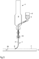
- the device shown also shows a fluid delivery device 4 which is designed as an eccentric screw pump 41 in the illustrated embodiment.
- the eccentric screw pump 41 also contains a reservoir 42 in which the liquid medium 6 is received.
- the liquid medium 6 is conveyed to the fluid guide device 3 by the eccentric screw pump 41 with a specifiable amount and / or a specifiable pressure.
- a connection element 45 is available for connecting the fluid guide device 3 to the eccentric screw pump 41.
- the connection element 45 can, for example, be a compression fitting or a Luer connection.
- the substrate 2 is mounted on a feed device 25, which generates a feed speed 255 in the form of an xy table with an optional rotation possibility of the substrate 2 in the plane spanned by the substrate.
- the substrate can be moved relative to the fluid conveying device 3 in order to generate lines of constant width with constant conveyance of the liquid medium by the fluid conveying device 4. If the delivery rate and / or the feed rate 255 vary over time, lines of different widths or taper can be generated.
- the exit of the liquid Medium 6 from the fluid guide device 3 can be controlled in that the second end 32 of the fluid guide device 3 is brought into contact with the substrate surface 6.
- a continuous conveyor such as a conveyor belt
- the fluid guiding device 3 can be coated by simply raising and lowering the fluid guiding device 3 at a constant pressure of the liquid medium 6 in the reservoir 42.
- Figure 4 shows how four parallel or concentric lines can be generated with four fluid guide devices 3.
- the fluid guide devices 3 are connected to one another by a common line 34.
- the second embodiment shown compared to the first embodiment described above consists in the type of fluid delivery device 4 used.
- the fluid delivery device 4 according to the second embodiment also has a reservoir 42 which is filled with the liquid medium 6.
- the reservoir 42 is subjected to a constant gas pressure via a line 421.
- the pressure is generated by a control or regulating device 7, which either contains a pressure reducer to relax a supplied compressed gas to a predeterminable, lower level or which contains a compression device with which a gas supplied at a lower pressure level is raised to a predeterminable higher pressure level can be.
- the gas used for this can be ambient air or an inert gas such as nitrogen or a noble gas, which is supplied via a gas supply 75.
- the thus pressurized liquid medium 6 escapes from the reservoir 42 via a riser 425.
- the riser 425 there are optional devices for measuring the pressure 73 or for measuring the flow rate 74.
- devices for pressure measurement and for flow measurement can also be present at the same time, as shown.
- the amount of liquid actually supplied to the fluid guide devices 3 is controlled or regulated via a valve 71.
- the valve 71 can for example be a piezo valve which responds quickly and can be controlled with short control times. This can also take place via the control or regulating device 7, which for this purpose can contain a microprocessor or a microcontroller.
- a syringe pump is used as the fluid delivery device.
- This contains a reservoir 42 which can be pressurized with a piston 43.
- the piston 43 is moved mechanically by a linear drive, for example a spindle drive 76. If the spindle 76 is driven by a stepping motor, the syringe pump can generate a uniform fluid flow of the liquid medium 6.
- the fourth embodiment includes elements of the third and second embodiments of the invention described above.
- a syringe body is used as the reservoir 42, which receives the liquid medium 6.
- the pressure required to convey the liquid medium 6 is not generated via a piston, but rather by supplying a pressurized gas to the reservoir 42 closed with a closure 44.
- the liquid medium 6 exits via an outlet arranged at the bottom in the reservoir 42, which in turn is directly connected to the fluid-guiding device 6.
- the gas pressure supplied to the reservoir 42 can in turn contain an inert gas or ambient air, it being possible for the gases to be supplied via a gas supply 75.
- An electrical or mechanical control valve 72 can be provided to set the required pressure.
- the inert gas supply device 5 essentially comprises a supply pipe 51 which opens into an outlet nozzle 54.
- the inert gas for example a noble gas or nitrogen, can optionally be heated to a desired temperature between approximately 30 ° C. and approximately 500 ° C. with a heating device 55.
- the fluid guide device 3 and the outlet nozzle 54 cooperate in such a way that the end of the second longitudinal section 32 opens below the outlet nozzle 54 or in the outlet area of the inert gas and the liquid medium is applied to the substrate 2 within the inert gas flow. If the inert gas stream is heated, it can contribute to the rapid drying of the liquid medium, so that the liquid medium hardens through crosslinking of its constituents and / or a solvent contained therein evaporates. At the same time, the inert gas prevents unwanted oxidation of the liquid medium or of the Surface 21 remaining components of the liquid medium.
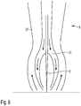
- an alternative inert gas supply device which has a supply line 51 which concentrically surrounds the fluid guide device 3 or a part or longitudinal section of the fluid guide device 3. In this way, the inert gas is supplied in a targeted manner where the liquid medium emerges from the fluid guide device 3. This can reduce the consumption of the inert gas.
- Figure 8 also shows an optional discharge line 52 which concentrically surrounds the supply line 51 and the fluid guide device 3.
- an optional discharge line 52 which concentrically surrounds the supply line 51 and the fluid guide device 3.
- a first embodiment of a drive device is explained in more detail. It shows Figure 9 a plurality of fluid guide devices 3 which are arranged with an assigned drive device 1 on a common carrier 16. In the illustrated embodiment, thirty-three fluid guide devices 3 are arranged in parallel. In other embodiments of the invention, the number of fluid guide devices 3 can also be larger or smaller, for example between 1 and approximately 50 or between approximately 10 and approximately 100. In this way, a number of lines corresponding to the number of fluid guide devices 3 can be applied from the liquid medium 6 to the substrate surface 21 at the same time. By parallelizing the order, the process time when applying the lines is shortened to the same extent, so that liquid media with the Process according to the invention can also be applied inexpensively to mass-produced articles.
- a fluid guide device 3 which contains a glass capillary with a first longitudinal section 31 with a comparatively large cross section and a second longitudinal section 32 in which the cross section tapers to the final diameter of, for example, approximately 0.5 ⁇ m to approximately 10 ⁇ m.
- the liquid medium is fed to the first longitudinal section 31 of the glass capillary via hose lines 33 which are fastened with a sealing and fastening element 34 and are supplied with the liquid medium via a fluid delivery device (not shown).
- a drive device 1 which can control or regulate the distance with great accuracy and / or high adjusting speed.
- the drive device 1 has a base element 15 which has a cantilever arm 17 which is separated from the rest of the base element 15 by a gap 16.
- a retaining clip 46 is arranged on the cantilever arm 17 and accommodates the fluid guiding device 3, for example by clamping the first longitudinal section 31 of a glass capillary.
- the base element 15 can be made of a polymer or a metal or an alloy.
- the drive device 1 also contains a piezo stack 11, the length of which changes when an electrical voltage is applied. This induces mechanical stresses in the base element 15, so that a movement of the cantilever arm 17 results from its deformation.
- the fluid guiding device 3 thus travels through an adjustment path 19 which, for example, is between approximately 100 ⁇ m to approximately 300 ⁇ m can and which can be passed through due to the rapid response speed of the piezo stack 11 with a frequency of about 200 Hz to about 2000 Hz.
- the drive device proposed according to the invention can thus vary the distance or the pressing force of the second longitudinal section 32 of the fluid guide device 3 on the substrate surface 21 with great accuracy and high speed, so that the fluid guide device 3 can be guided with great precision on the substrate surface 21 without the substrate surface 21 or the fluid guide device 3 is damaged.
- the drive device 1 also contains a base element 15 which is provided for receiving the fluid guide device 3.
- a glass capillary with its first longitudinal section 31 can be held in a clamp 46.
- the basic elements 15 have a shape which enables an endless array of a plurality of fluid guide devices 3 in order to parallelize the delivery of the liquid medium.
- Figure 11 only nine parallel fluid guide devices are shown. However, as explained above, this number can also be larger or smaller.
- the invention does not teach the use of exactly nine fluid guide devices as a solution principle.
- no piezo stack 11 which changes its length when a voltage is applied, but a bending piezo 12 which bends up or down like a bimetal when an electrical voltage is applied.
- the bending piezo 12 is arranged directly in the gap 16 of the base element 15 and thus acts directly on the A cantilever arm 17, which is thus also deflected upwards or downwards along the travel 19 in a manner corresponding to the movement of the bending piezo 12.
- the exemplary embodiment is based on the generation of a front-side contact of a photovoltaic cell.
- Such front-side contacts are applied as a line or grid structure in order to simultaneously couple light into the semiconductor material of the photovoltaic cell and dissipate the resulting electric current.
- an aqueous suspension which contains about 4% by volume of metallic nanoparticles is used to produce the front-side contact.
- the degree of filling of the metal in the entire aqueous solution is thus about 50% by weight.
- the nanoparticles can contain or consist of silver.
- the viscosity of this suspension is between 5 mPa ⁇ s and 20 mPa ⁇ s.
- such suspensions are applied by the inkjet process, i. E. ejected in the form of small droplets from a print head and applied to the substrate surface.
- the lines that can be generated have a width of more than 40 ⁇ m.
- the fluid guide device used according to the invention contains a glass capillary with an inner diameter of approximately 6 ⁇ m at the end of the second longitudinal section 32.
- a glass capillary is sold, for example, by Eppendorf under the order number 5195000087.
- the inner diameter of the fluid guide device 3 is selected so that it is greater than approximately 5 to 8 times the average particle diameter of the metallic nanoparticles in the suspension used.
- the liquid medium was ejected from the fluid guide devices by a fluid conveying device at a pressure of approximately 100 mbar and applied to a photovoltaic cell with an approximately square basic shape and an edge length of 156 mm.
- the surface was provided with a pyramid-shaped texture and a coating which contains indium tin oxide. For 80 lines, each running over the entire length of the cell and each having a width of 16 ⁇ 1 ⁇ m, a total of only 0.3 ⁇ 0.1 mg of the suspension was consumed. After the suspension has dried, it has a higher silver content than conventional screen printing pastes, which results in better conductivity than with known printed front-side contacts.
- front-side contacts can be produced more quickly and with a smaller structure size than in the screen printing or inkjet method, the consumption of the silver-containing suspension is reduced and, at the same time, improved front-side contacts with higher electrical conductivity can be produced.
Landscapes
- Physics & Mathematics (AREA)
- Fluid Mechanics (AREA)
- Coating Apparatus (AREA)
- Application Of Or Painting With Fluid Materials (AREA)
- Manufacturing Of Printed Circuit Boards (AREA)
Abstract
Description
- Die Erfindung betrifft eine Vorrichtung zum Aufbringen flüssiger Medien auf eine Substratoberfläche, enthaltend eine Fluidführungseinrichtung und zumindest eine Fluidfördereinrichtung und zumindest eine Vorschubeinrichtung zur Erzeugung einer Relativbewegung zumindest zwischen der Substratoberfläche und einem Teil der Fluidführungseinrichtung. Weiterhin betrifft die Erfindung ein Verfahren zum Aufbringen flüssiger Medien auf eine Substratoberfläche, bei welchem das flüssige Medium mit zumindest einer Fluidfördereinrichtung zu zumindest einer Fluidführungseinrichtung gefördert wird, wobei mit zumindest einer Vorschubeinrichtung eine Relativbewegung zumindest zwischen der Substratoberfläche und einem Teil der Fluidfördereinrichtung erzeugt wird. Vorrichtungen und Verfahren dieser Art können zur Herstellung von Leiterbahnen oder elektrischen Kontakten auf Halbleitersubstraten, zum lokalen Aufbringen eines Ätzmittels oder für generative Herstellungsverfahren verwendet werden.
- Aus der Praxis ist bekannt, zur Erzeugung eines Vorderseitenkontaktes auf einer photovoltaischen Zelle eine Siebdruckpaste mit Metallpartikeln durch eine Dosiernadel auf der Oberfläche eines Halbleitersubstrates abzulegen und durch nachfolgendes Tempern einen ohmschen Kontakt auszubilden. Die hierfür verwendete Dosiernadel weist Durchmesser von mehr als 60 µm auf, sodass auch die kleinste hiermit erzielbare Strukturgröße des Vorderseitenkontaktes nicht geringer sein kann. Darüber hinaus sind die erzielbaren Übergangswiderstände oftmals zu hoch und der Kontakt dadurch unzulänglich.
- Ausgehend vom Stand der Technik liegt der Erfindung somit die Aufgabe zugrunde, Strukturen mit kleinen Abmessungen mit hoher Zuverlässigkeit und kurzen Bearbeitungszeiten auf Substratoberflächen zu erzeugen.
- Die Aufgabe wird erfindungsgemäß durch eine Vorrichtung gemäß Anspruch 1, deren Verwendung nach Anspruch 9 und ein Verfahren nach Anspruch 10 gelöst. Vorteilhafte Weiterbildungen der Erfindung finden sich in den Unteransprüchen.
- Erfindungsgemäß wird eine Vorrichtung zum Aufbringen flüssiger Medien vorgeschlagen, welche eine Fluidführungseinrichtung enthält. Die Fluidführungseinrichtung kann in einigen Ausführungsformen der Erfindung eine Kapillare aus Glas oder Quartz oder Kunststoff sein oder eine solche Kapillare enthalten. Die Kapillare kann zumindest in einem Teilabschnitt biegsam sein, sodass diese bei Betrieb der Vorrichtung auf der Substratoberfläche aufgesetzt werden kann. Daneben kann die Fluidführungseinrichtung in an sich bekannter Weise ein Schlauchsystem beziehungsweise ein Rohrsystem zur Zufuhr des flüssigen Mediums enthalten. Erfindungsgemäß wird somit vorgeschlagen, ein flüssiges Medium durch eine oder mehrere Kapillaren auf eine Substratoberfläche aufzubringen. Das zum Austritt des flüssigen Mediums bestimmte offene Ende der Kapillare wird dabei gleitend auf der Substratoberfläche geführt.
- Der Außendurchmesser der Kapillare kann in zumindest einem Teilabschnitt an dem der Substratoberfläche zugewandten Ende bzw. an der mit der Substratoberfläche in Kontakt stehenden Öffnung geringer sein als etwa 25 µm oder etwa 15 µm oder etwa 10 µm oder etwa 7 µm. Erfindungsgemäß wurde erkannt, dass der Außendurchmesser der Kapillare die Strukturbreite des auf der Substratoberfläche abgelegten Strangs des flüssigen Mediums beeinflusst, sodass mit den offenbarten Kapillaren auch kleine Strukturen erzeugbar sind. Der Außendurchmesser der Kapillare kann in zumindest einem Teilabschnitt an dem der Substratoberfläche zugewanden Ende bzw. an der mit der Substratoberfläche in Kontakt stehenden Öffnung einen Außendurchmesser aufweisen, welcher größer ist als etwa 1 µm oder größer ist als etwa 3 µm oder größer ist als etwa 5 µm.
- In einigen Ausführungsformen der Erfindung kann die Kapillare einen ersten Längsabschnitt aufweisen, welcher gegenüber einem zweiten Längsabschnitt der Kapillare angewinkelt bzw. gebogen ist. Der erste und der zweite Längsabschnitt können einen Winkel von etwa 170° bis etwa 100° oder von etwa 160° bis etwa 110° oder von etwa 150° bis etwa 120° einschließen. In anderen Ausführungsformen der Erfindung kann die Kapillare gerade sein, d.h. der erste und der zweite Längsabschnitt schließen einen Winkel von etwa 180° ein. In diesem Fall kann die Kapillare in der Vorrichtung geneigt eingebaut sein, so dass diese zumindest im Betrieb der Vorrichtung einen Winkel von etwa 80° bis etwa 10° oder von etwa 70° bis etwa 20° oder von etwa 30° bis etwa 45° oder von etwa 20° bis etwa 10° zum Normalenvektor der Substratoberfläche einschließt. Dies reduziert die Beschädigung der in Kontakt mit der Kapillare stehenden Substratoberfläche und/oder kann die Bruchgefahr der Kapillare reduzieren.
- Zur Zufuhr des flüssigen Mediums in die Fluidführungseinrichtung dient zumindest eine Fluidfördereinrichtung, welche das flüssige Medium mit konstantem Druck und/oder konstanter Durchflussrate in die Fluidführungseinrichtung und nachfolgend auf die Substratoberfläche fördert.
- Erfindungsgemäß ist keine vollflächige Beschichtung der Substratoberfläche mit dem flüssigen Medium vorgesehen, sondern das Aufbringen einer Teilbeschichtung beziehungsweise einer Beschichtung, welche nur eine Teilfläche der Substratoberfläche belegt. Die beschichteten Teilflächen können eine oder mehrere gerade oder gekrümmte Linien bilden. Diese können in konstantem Abstand nebeneinander verlaufen und/oder sich mit weiteren Linien kreuzen. Eine einzelne Linie bzw. Teilfläche kann eine Breite von etwa 50 µm bis etwa 2 µm oder von etwa 30 µm bis etwa 2 µm oder etwa 15 µm bis etwa 4 µm aufweisen. In anderen Ausführungsformen der Erfindung kann die mit dem flüssigen Medium beschichtete Teilfläche kreis- bzw. punktförmig sein oder eine Mehrzahl von Einzelpunkten entlang einer Linie aufweisen.
- Zur Erzeugung einer ausgedehnten Teilfläche bzw. Linie weist die erfindungsgemäße Vorrichtung zumindest eine Vorschubeinrichtung auf, welche der Erzeugung einer Relativbewegung zwischen zumindest einem Teil der Fluidführungseinrichtung und der Substratoberfläche dient. In einigen Ausführungsformen der Erfindung kann die Vorschubeinrichtung einen Linearantrieb enthalten oder daraus bestehen. In diesem Fall kann die Vorrichtung zum Aufbringen flüssiger Medien Punktfolgen oder durchgehende oder unterbrochene Linien erzeugen. Eine Mehrzahl paralleler Linien kann durch mehrere, parallel angeordnete Fluidführungseinrichtung erzeugt werden.
- In einigen Ausführungsformen der Erfindung kann die Vorschubeinrichtung einen x-y-Tisch enthalten oder daraus bestehen, sodass das Substrat unter einer statischen Fluidführungseinrichtung in zwei Richtungen bewegbar ist. Die Bewegung in zwei Achsen erlaubt das Aufbringen einer Mehrzahl paralleler Linien mit einer Fluidführungseinrichtung oder auch die Erzeugung gekrümmter oder gitterförmiger Linien. Alternativ oder zusätzlich kann die Vorschubeinrichtung auch eine Rotation um zumindest eine Achse ermöglichen, beispielsweise um die Normalenrichtung der durch den x-y-Tisch aufgespannten Ebene. Somit können in einfacher Weise runde oder spiralförmige Linien oder auch gerade Linien in unterschiedlichen Richtungen erzeugt werden.
- Erfindungsgemäß kommt es lediglich auf eine relative Bewegung zwischen der Substratoberfläche und zumindest einem Teil der Fluidfördereinrichtung an. Daher kann selbstverständlich auch das Substrat ortsfest gelagert werden, wenn die Vorschubeinrichtung dazu eingerichtet ist, die gesamte Fluidführungseinrichtung oder zumindest einen Teil der Fluidführungseinrichtung zu bewegen. In einigen Ausführungsformen der Erfindung ist die Vorschubeinrichtung dazu eingerichtet, eine relative Bewegung zwischen dem Substrat und der Fluidführungseinrichtung beziehungsweise einem Teil der Fluidführungseinrichtung innerhalb der durch das Substrat definierten Ebene zu ermöglichen.
- Das Substrat kann in einigen Ausführungsformen der Erfindung ein Halbleitermaterial sein, welches mit elektrischen Kontakten versehen wird. In einigen Ausführungsformen der Erfindung kann das Halbleitersubstrat eine photovoltaische Zelle sein, welche mit einem Vorderseiten- oder einem Rückseitenkontakt versehen wird. In anderen Ausführungsformen der Erfindung kann das Substrat ein Metall, eine Legierung oder ein Halbleitermaterial enthalten, auf welches lokal ätzende Medien aufgebracht werden, um auf diese Weise Strukturen in der Substratoberfläche zu erzeugen. In wiederum anderen Ausführungsformen der Erfindung kann das flüssige Medium ein explosives Medium, ein pyrophores Medium und/oder ein Medium mit niedrigem Dampfdruck sein. In diesen Fällen ermöglicht die erfindungsgemäße Vorrichtung beispielsweise eine Solarzellenproduktion unter Verwendung von Silanen, insbesondere Monosilan. In wiederum anderen Ausführungsformen ermöglicht die Erfindung die Herstellung von Verbindungshalbleitern, beispielsweise unter Verwendung von Monophosphan oder anderen, schwer handhabbaren Precursoren.
- In wiederum anderen Ausführungsformen der Erfindung kann das flüssige Medium Nanopartikel enthalten, beispielsweise Partikel aus einem Metall oder einer Legierung, welche nach Verdampfen eines flüssigen Lösungsmittels und einem optionalen Sinter- oder Temperschritt elektrisch leitfähige Strukturen ausbilden. In wiederum anderen Ausführungsformen der Erfindung kann das flüssige Medium lebende Zellen enthalten, welche in einem 3D-Druckverfahren zu größeren Organismen und/oder Organen zusammengesetzt werden können. Alternativ können lebende Zellen zur Durchführung biologischer Experimente mit hoher Genauigkeit auf einem Objektträger oder einem Lab-on-Chip abgelegt werden.
- In einigen Ausführungsformen der Erfindung kann die Vorrichtung weiterhin zumindest eine Antriebseinrichtung zur Veränderung des Abstandes zwischen der Substratoberfläche und einem Teil eines zweiten Längsabschnittes der Fluidführungseinrichtung enthalten. Die Antriebseinrichtung ist dazu vorgesehen, einerseits eine Beschädigung der Kapillare der Fluidführungseinrichtung zu vermeiden und andererseits eine Beschädigung der Substratoberfläche durch hartes Aufsetzen der Fluidführungseinrichtung zu vermeiden. Hierzu ist eine Antriebseinrichtung vorgesehen, welche den Abstand mit hoher Genauigkeit und hoher Regelgeschwindigkeit einstellen kann. Hierdurch wird ermöglicht, dass der mit der Substratoberfläche in Kontakt stehende Längsabschnitt der Fluidführungseinrichtung, z.B. das Ende einer Glaskapillare, entweder in geringem Abstand über der Substratoberfläche geführt wird oder aber die Glaskapillare in Kontakt mit der Substratoberfläche mit geringer Anpresskraft gleitet, sodass eine Beschädigung der Substratoberfläche und der Kapillare vermieden wird. Weiterhin dient das Einhalten eines konstanten Abstandes bzw. eines konstanten Anpressdruckes dazu, eine Linie konstanter Breite zu erzeugen.
- In einigen Ausführungsformen der Erfindung kann eine Einrichtung zur Abstandserfassung vorhanden sein, welche den Abstand zwischen der Substratoberfläche und einem Teil eines zweiten Längsabschnittes der Fluidführungseinrichtung bestimmt. Hierzu kann eine optische Abstandsmessung erfolgen, beispielweise durch Bildverarbeitung eines Mikroskopbildes oder durch Laserinterferenz. In anderen Ausführungsformen der Erfindung kann die Anpresskraft zwischen der Substratoberfläche und der Fluidführungseinrichtung als Maß für den Abstand beider Bauteile herangezogen werden. Der so erfasste Ist-Wert des Abstandes kann mit einem vorgebbaren Soll-Wert verglichen und zur Regelung der Antriebseinrichtung verwendet werden.
- In einigen Ausführungsformen der Erfindung kann die Antriebseinrichtung zumindest einen Piezosteller enthalten oder daraus bestehen. Eine solche Antriebseinrichtung ermöglicht eine rasche Verstellung, sodass auch bei hoher Vorschubgeschwindigkeit der Abstand zwischen der Fluidführungseinrichtung und der Substratoberfläche gesteuert oder geregelt werden kann, ohne unzulässig hohe Kräfte auf die Substratoberfläche aufzubringen dadurch die Fluidführungseinrichtung oder die Substratoberfläche zu beschädigen.
- In einigen Ausführungsformen der Erfindung kann die Antriebseinrichtung einen Stellweg von etwa 100 µm bis etwa 300 µm oder von etwa 150 µm bis etwa 250 µm oder von etwa 180 µm bis etwa 220 µm ermöglichen. Dieser Stellweg reicht aus, um unerwünschte Kollisionen der Fluidfördereinrichtung mit der Substratoberfläche zu verhindern, sodass eine Beschädigung des Substrates oder der Fluidführungseinrichtung vermieden wird.
- In einigen Ausführungsformen der Erfindung kann die Antriebseinrichtung dazu eingerichtet sein, den Stellweg mit einer Frequenz von etwa 200 Hz bis etwa 2000 Hz oder von etwa 500 Hz bis etwa 1500 Hz oder von etwa 800 Hz bis etwa 1200 Hz zu durchfahren. Eine hohe Stellgeschwindigkeit der Antriebseinrichtung ermöglicht den Ausgleich von Unebenheiten auf der Substratoberfläche und/oder das Aufsetzen und Anheben der Fluidführungseinrichtung von der Substratoberfläche auch bei hohen Vorschubgeschwindigkeiten der Vorschubeinrichtung, sodass die Bearbeitungsgeschwindigkeit beim Aufbringen flüssiger Medien erhöht sein kann.
- In einigen Ausführungsformen der Erfindung kann die Fluidführungseinrichtung zumindest einen zweiten Längsabschnitt aufweisen, welcher einen Innendurchmesser von etwa 0,5 µm bis etwa 10 µm oder von etwa 2 µm bis etwa 8 µm oder von etwa 4 µm bis etwa 6 µm aufweist. Dieser zweite Längsabschnitt ist dazu eingerichtet und bestimmt, das distale Ende der Fluidführungseinrichtung zu bilden und damit diejenige Öffnung zu definieren, durch welche das flüssige Medium auf die Substratoberfläche aufgebracht wird. Da der Durchmesser somit etwa einen Faktor 6 bis 10 geringer ist als bei bekannten Dosiernadeln, können die mit der erfindungsgemäßen Vorrichtung erzeugten Strukturen auf der Substratoberfläche ebenfalls einen Faktor 5 bis 10 geringer sein.
- In einigen Ausführungsformen der Erfindung kann die Fluidfördereinrichtung eine Exzenterschneckenpumpe oder eine Kolbenpumpe oder eine Spritzenpumpe enthalten oder daraus bestehen. Diese Fluidfördereinrichtungen lassen sich in Durchfluss und Druck präzise regeln, sodass die Fördermenge des flüssigen Mediums durch die Fluidführungseinrichtung präzise kontrollierbar ist und dadurch auch die erzeugten Strukturen in Breite und/oder Längsausdehnung präzise kontrollierbar sind.
- In einigen Ausführungsformen der Erfindung kann die Fluidfördereinrichtung dazu eingerichtet sein, das flüssige Medium mit einem Druck von etwa 100 mbar bis etwa 500 mbar oder von etwa 150 mbar bis etwa 300 mbar oder von etwa 500 mbar bis etwa 5000 mbar oder von etwa 1000 mbar bis etwa 2000 mbar von etwa 0 mbar bis etwa 100 mbar zu fördern. Die genannten Druckbereiche ermöglichen einerseits, auch flüssige Medien, welche beispielsweise Nanopartikel enthalten und hierdurch eine höhere Viskosität aufweisen, zuverlässig durch eine dünne Fluidführungseinrichtung zu fördern. Andererseits sind die Drücke gering genug, um beispielsweise lebende Zellen bei der Applikation auf der Substratoberfläche nicht zu zerstören.
- In einigen Ausführungsformen der Erfindung kann die Vorschubeinrichtung dazu eingerichtet sein, mit einer Vorschubgeschwindigkeit von etwa 100 mm/s bis etwa 1000 mm/s oder von etwa 300 mm/s bis etwa 900 mm/s oder von etwa 500 mm/s bis etwa 800 mm/s betrieben zu werden. Dies erlaubt eine rasche Fertigung insbesondere geradliniger Strukturen mit der erfindungsgemäßen Vorrichtung, sodass Massenartikel wie beispielsweise Solarzellen insbesondere bei paralleler Aufbringung der Vorderseitenkontakte mit einer Mehrzahl von Fluidführungseinrichtungen mit einem Durchsatz bis 23000 Wafer pro Stunde prozessiert werden können. Damit hat sich überraschend gezeigt, dass das auf den ersten Blick sehr aufwendig erscheinende Verfahren gleichwohl einen hohen Durchsatz erlaubt, sodass die erfindungsgemäße Vorrichtung und das erfindungsgemäße Verfahren das Potenzial haben, üblichen Sieb- oder Tampondruck bei der Herstellung von Solarzellen abzulösen, bei gleichzeitig sinkenden Strukturgrößen der Vorderseitenkontakte.
- In einigen Ausführungsformen der Erfindung enthält die Vorrichtung weiterhin ein Ventil zur Regelung des Volumenstroms des aus der Fluidführungseinrichtung austretenden flüssigen Mediums. Diese Ausführungsform der Erfindung erlaubt es, das aufzubringende flüssige Medium mittels der Fluidfördereinrichtung mit kontantem Druck zu beaufschlagen und den Volumenstrom allein durch das Öffnen und schließen eines Ventils zu steuern bzw. zu regeln. Hierdurch kann ein schnelles Regelverhalten erreicht werden, was die Toleranzen der Strukturbreite reduziert und/oder das An- und Absetzen am Anfang und Ende eines Substrates, beispielsweise eines Wafers, weiter beschleunigt.
- In einigen Ausführungsformen der Erfindung kann die Vorrichtung weiterhin eine Intergaszufuhreinrichtung enthalten. In diesem Fall können auch sensible Medien, beispielsweise Stoffe, die zur Selbstentzündung neigen oder an Luft rasch oxidieren verarbeitet werden.
- In einigen Ausführungsformen der Erfindung kann die Intergaszufuhreinrichtung einer Zufuhrleitung aufweisen, welche die Fluidführungseinrichtung konzentrisch umgibt. Weiterhin kann die Intergaszufuhreinrichtung eine optionale Abfuhrleitung aufweisen, welche die Zufuhrleitung konzentrisch umgibt. Hierdurch ist es möglich, nicht nur ein Inertgas zuzuführen, sondern auch das Inertgas und/oder Bestandteile des flüssigen Mediums über die Abfuhrleitung abzusaugen, sodass sich die Vorrichtung auch für die Verarbeitung toxischer Medien eignen kann.
- In einigen Ausführungsformen der Erfindung kann die Intergaszufuhreinrichtung eine Heizeinrichtung enthalten, mit welcher das zugeführte Inertgas erwärmbar ist.
- In einigen Ausführungsformen der Erfindung kann das flüssige Medium eine Viskosität von etwa 5 mPa·s bis etwa 200 mPa·s oder von etwa 5 mPa·s bis etwa 20 mPa·s aufweisen. Diese Medien lassen sich auch durch Fluidführungsvorrichtungen mit kleinem Innendurchmesser fördern.
- In einigen Ausführungsformen der Erfindung kann das flüssige Medium metallische Nanopartikel mit einer Konzentration von etwa 2 Vol.-% bis etwa 10 Vol.-% oder von etwa 2 Vol.-% bis etwa 6 Vol.-% oder von etwa 3 Vol.-% bis etwa 5 Vol.-% enthalten. Beispielsweise kann das flüssige Medium eine leitfähige InkJet-Tinte sein, mit welcher leitfähige Strukturen wie beispielsweise Vorderseitenkontakte auf photovoltaischen Zellen in einem Tintenstrahldruckverfahren aufgebracht werden können. Anders als bei der Verarbeitung im Tintenstrahldruckverfahren wird das flüssige Medium erfindungsgemäß jedoch stetig gefördert und nicht in Form einzelner Tropfen aufgebracht. Hierdurch können die erfindungsgemäß hergestellten Strukturen wesentlich feiner sein und beispielsweise Breitenausdehnungen quer zur Vorschubgeschwindigkeit von etwa 2 µm bis etwa 10 µm aufweisen. Durch den kontinuierlichen Materialfluss wird darüber hinaus vermieden, dass sich zwischen einzelnen Tröpfchen unzulässig große Übergangswiderstände ausbilden, sodass die erfindungsgemäß hergestellten leitfähigen Kontakte eine erhöhte Leitfähigkeit beziehungsweise einen geringen ohmschen Widerstand aufweisen können.
- In einigen Ausführungsformen der Erfindung erfolgt beim Aufsetzen der Fluidführungseinrichtung auf die Substratoberfläche eine Relativbewegung zwischen der Fluidführungseinrichtung und der Substratoberfläche. Hierdurch wird vermieden, dass durch einen harten Anprall der Fluidführungseinrichtung auf das Substrat die Substratoberfläche und/oder die Fluidführungseinrichtung beschädigt wird.
- Nachfolgend soll die Erfindung anhand von Figuren ohne Beschränkung des allgemeinen Erfindungsgedankens näher erläutert werden. Dabei zeigt
-
Figur 1 Fluidführungseinrichtungen auf einem Substrat. -
Figur 2 zeigt einen Ausschnitt ausFigur 1 . -
Figur 3 zeigt eine Vorrichtung zum Aufbringen flüssiger Medien in einer ersten Ausführungsform. -
Figur 4 zeigt eine Vorrichtung zum Aufbringen flüssiger Medien in einer zweiten Ausführungsform. -
Figur 5 zeigt eine Vorrichtung zum Aufbringen flüssiger Medien in einer dritten Ausführungsform. -
Figur 6 zeigt eine Vorrichtung zum Aufbringen flüssiger Medien in einer vierten Ausführungsform. -
Figur 7 zeigt eine Vorrichtung zum Aufbringen flüssiger Medien mit einer Intergaszufuhreinrichtung in einer ersten Ausführungsform. -
Figur 8 zeigt eine Intergaszufuhreinrichtung in einer zweiten Ausführungsform. -
Figur 9 zeigt eine Fluidführungseinrichtung mit Antriebseinrichtung in einer ersten Ausführungsform. -
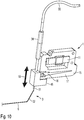
Figur 10 zeigt einen Ausschnitt ausFigur 9 . -
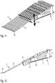
Figur 11 zeigt eine Fluidführungseinrichtung mit Antriebseinrichtung in einer zweiten Ausführungsform. -
Figur 12 zeigt einen Ausschnitt ausFigur 11 . - Anhand der
Figuren 1 und 2 werden Fluidführungseinrichtungen erläutert, welche zum Aufbringen flüssiger Medien verwendbar sind. Dabei zeigtFigur 1 eine Mehrzahl parallel angeordneter Fluidführungseinrichtungen auf einem Substrat 2 undFigur 2 zeigt einen Ausschnitt einer einzelnen Fluidführungseinrichtung im Betrieb. - Die Figuren zeigen ein Substrat 2 mit einer Substratoberfläche 21. Das Substrat 2 kann beispielsweise ein Halbleitermaterial sein, wie zum Beispiel eine photovoltaische Zelle, welche mit einem Vorderseitenkontakt versehen werden soll. Zum Aufbringen der Vorderseitenkontakte aus einer mit metallischen Nanopartikeln gefüllten leitfähigen Tinte wird die erfindungsgemäße Vorrichtung mit einer Mehrzahl von Fluidführungseinrichtungen 3 verwendet. Im dargestellten Ausführungsbeispiel sind fünf parallel angeordnete Fluidführungseinrichtungen vorgesehen. In anderen Ausführungsformen der Erfindung kann die Anzahl der Fluidführungseinrichtungen auch größer oder geringer sein und beispielsweise zwischen eins und etwa fünfzig betragen. Hierdurch kann eine Mehrzahl paralleler Linien gleichzeitig auf das Substrat 2 aufgebracht werden, wodurch sich die Bearbeitungszeit reduziert.
- Wie
Figur 1 weiter zeigt, weist die Fluidführungseinrichtung 3 zumindest einen ersten Längsabschnitt 31 auf, welcher einen vergleichsweise großen Durchmesser hat und dadurch eine höhere mechanische Stabilität besitzt sowie einen zweiten Längsabschnitt 32, welcher aufgrund seines geringeren Durchmessers eine geringere mechanische Stabilität aufweist. Der zweite Längsabschnitt 32 ist stromabwärts des ersten Längsabschnittes 31 angeordnet. Der zweite Längsabschnitt 32 kann zumindest abschnittsweise einen Innendurchmesser von etwa 0,5 µm bis etwa 10 µm oder von etwa 2 µm bis etwa 8 µm oder von etwa 4 µm bis etwa 6 µm aufweisen. Der Außendurchmesser ist um die Wandstärke des zweiten Längsabschnittes vergrößert, welche zwischen etwa 1 µm bis eta 4 µm beträgt. Hierdurch definiert der Außendurchmesser des zweiten Längsabschnitt 32 die Breite der erzeugten Strukturen. Dieser Teil der Fluidführungseinrichtung kann aus einer Glaskapillare gebildet werden bzw. eine Glaskapillare enthalten. - Wie
Figur 2 weiter zeigt, steht der zweite Längsabschnitt 32 mechanisch im Kontakt mit der Substratoberfläche 21, wodurch in Abhängigkeit von Abstand und Anpresskraft eine Biegung der Fluidführungseinrichtung 3 an deren distalen Ende vorliegen kann. Zwischen der Fluidführungseinrichtung 3 und dem Substrat 2 wird durch eine nicht dargestellte Vorschubeinrichtung eine Relativbewegung 255 erzeugt. Bei gleichzeitigem Fördern des flüssigen Mediums 6 durch die Fluidfördereinrichtung wird das flüssige Medium 6 in einer Linie auf der Substratoberfläche 21 abgelegt. Soweit es sich hierbei um eine leitfähig gefüllte Tinte handelt, kann der so erzeugte Vorderseitenkontakt durch nachträgliches Tempern mechanisch stabilisiert und/oder elektrisch aktiviert werden. - Es wurde erkannt, dass sich an der Öffnung der Fluidfördereinrichtung unter konstantem Druck des flüssigen Mediums 6 ein Tropfen bildet, welcher den weiteren Austritt des flüssigen Mediums aus der Fluidfördereinrichtung 3 verhindert, so lange diese nicht in Kontakt mit der Substratoberfläche 21 steht. Beim Aufsetzen des zweiten Längsabschnittes 32 der Fluidfördereinrichtung 3 auf die Substratoberfläche 21 startet der Flüssigkeitsstrom bei konstantem Druck selbsttätig, wenn die Oberflächenenergie der Substratoberfläche 21 höher ist als die Oberflächenenergie der Oberfläche der des zweiten Längsabschnittes 32 der Fluidfördereinrichtung 3. Beispielsweise kann das flüssige Medium eine wässrige Lösung oder Suspension sein, wenn die Substratoberfläche 21 hydrophil ist und zumindest der zweite Längsabschnitt 32 der Fluidfördereinrichtung 3 hydrophob ist. In diesem Fall kann der auf das Substrat aufgebrachte Strom allein durch den Abstand bzw. den Anpressdruck des zweiten Längsabschnittes 32 der Fluidfördereinrichtung 3 auf der Substratoberfläche 21 gesteuert bzw. geregelt werden. Bei unpolaren Flüssigkeiten können die jeweiligen Oberflächenenergien entsprechend gewählt werden.
-
Figur 3 zeigt eine erste Ausführungsform der erfindungsgemäßen Vorrichtung. Dargestellt ist wiederum ein Substrat 2 mit einer Substratoberfläche 21, auf welche ein flüssiges Medium 6 aufgebracht werden soll. Hierzu steht, wie vorstehend in Verbindung mitFigur 1 und 2 beschrieben, die Fluidführungseinrichtung 3 zur Verfügung, welche mit ihrem zweiten Längsabschnitt 32 im Kontakt mit der Substratoberfläche 21 steht. Die Fluidführungseinrichtung 3 kann in einigen Ausführungsformen der Erfindung aus Glas oder Kunststoff bestehen und ist aufgrund ihres geringen Außendurchmessers mechanisch biegsam, sodass sich die inFigur 3 undFigur 2 gezeigte Form aufgrund der Relativbewegung 255 ausbildet. - Die in
Figur 3 gezeigte Vorrichtung zeigt weiterhin eine Fluidfördereinrichtung 4 welche im dargestellten Ausführungsbeispiel als Exzenterschneckenpumpe 41 ausgeführt ist. Die Exzenterschneckenpumpe 41 enthält darüber hinaus ein Reservoir 42, in welchem das flüssige Medium 6 aufgenommen ist. Das flüssige Medium 6 wird durch die Exzenterschneckenpumpe 41 mit vorgebbarer Menge und/oder vorgebbarem Druck zur Fluidführungseinrichtung 3 gefördert. Zur Verbindung der Fluidführungseinrichtung 3 mit der Exzenterschneckenpumpe 41 steht ein Anschlusselement 45 zur Verfügung. Das Anschlusselement 45 kann beispielsweise eine Quetschverschraubung oder ein Luer-Anschluss sein. - Anhand von
Figur 4 wird eine zweite Ausführungsform der erfindungsgemäßen Vorrichtung erläutert. Gleiche Bestandteile der Erfindung sind mit gleichen Bezugszeichen versehen, sodass sich die nachfolgende Beschreibung auf die wesentlichen Unterschiede beschränkt. - Wie
Figur 4 zeigt, ist das Substrat 2 auf einer Vorschubeinrichtung 25 montiert, welche in Form eines x-y-Tisches mit einer optionalen Rotationsmöglichkeit des Substrates 2 in der durch das Substrat aufgespannten Ebene eine Vorschubgeschwindigkeit 255 erzeugt. Hierdurch kann das Substrat relativ zur Fluidführungseinrichtung 3 bewegt werden, um so bei konstanter Förderung des flüssigen Mediums durch die Fluidfördereinrichtung 4 Linien konstanter Breite zu Erzeugen. Sofern die Fördermenge und/oder die Vorschubgeschwindigkeit 255 zeitlich variiert, können Linien unterschiedlicher Breite bzw. Taper erzeugt werden. Wie vorstehend beschrieben wurde, kann der Austritt des flüssigen Mediums 6 aus der Fluidführungsvorrichtung 3 dadurch kontrolliert werden, dass das zweite Ende 32 der Fluidführungsvorrichtung 3 mit der Substratoberfläche 6 in Kontakt gebracht wird. Somit können in einigen Ausführungsformen der Erfindung mehrere, auf einem Stetigförderer, wie zum Beispiel einem Förderband, unter der Fluidführungsvorrichtung 3 hindurch transportierte Substrate durch einfaches Anheben und Absenken der Fluidführungsvorrichtung 3 bei konstantem Druck des Flüssigen Mediums 6 im Reservoir 42 beschichtet werden. -
Figur 4 zeigt, wie mit vier Fluidführungseinrichtungen 3 vier parallele beziehungsweise konzentrische Linien erzeugt werden können. Um eine gleichmäßige Zufuhr des flüssigen Mediums zu ermöglichen, sind die Fluidführungseinrichtungen 3 durch eine gemeinsame Leitung 34 miteinander verbunden. - Der weitere Unterschied der in
Figur 4 gezeigten zweiten Ausführungsform gegenüber der vorstehend beschriebenen ersten Ausführungsform besteht in der Art der verwendeten Fluidfördereinrichtung 4. Auch die Fluidfördereinrichtung 4 gemäß der zweiten Ausführungsform weist eine Reservoir 42 auf, welches mit dem flüssigen Medium 6 gefüllt ist. Das Reservoir 42 wird über eine Leitung 421 mit einem konstanten Gasdruck beaufschlagt. Der Druck wird über eine Steuer- oder Regeleinrichtung 7 erzeugt, welche entweder einen Druckminderer enthält, um ein zugeführtes Druckgas auf ein vorgebbares, niedrigeres Niveau zu entspannen oder welcher eine Kompressionseinrichtung enthält, mit dem ein auf niedrigerem Druckniveau zugeführtes Gas auf ein vorgebbares höheres Druckniveau angehoben werden kann. Das hierzu verwendete Gas kann Umgebungsluft sein oder aber ein Inertgas wie beispielsweise Stickstoff oder ein Edelgas, welches über eine Gaszufuhr 75 zugeführt wird. - Das so unter Druck gesetzte flüssige Medium 6 entweicht aus dem Reservoir 42 über eine Steigleitung 425. In der Steigleitung 425 finden sich optionale Einrichtungen zum Messen des Druckes 73 oder zur Messung des Durchflusses 74. In einigen Ausführungsformen können auch wie dargestellt Einrichtungen zur Druckmessung und zur Durchflussmessung gleichzeitig vorhanden sein. Die den Fluidführungseinrichtungen 3 tatsächlich zugeführte Flüssigkeitsmenge wird über ein Ventil 71 gesteuert oder geregelt. Das Ventil 71 kann beispielsweise ein Piezoventil sein, welches rasch anspricht und mit kurzen Regelzeiten angesteuert werden kann. Auch dies kann über die Steuer- oder Regeleinrichtung 7 erfolgen, welcher hierzu einen Mikroprozessor oder einen Mikrocontroller enthalten kann.
- Anhand der
Figur 5 wird eine dritte Ausführungsform der vorliegenden Erfindung erläutert. Gleiche Bestandteile sind wiederum mit gleichen Bezugszeichen versehen, sodass sich die folgende Beschreibung auf die wesentlichen Unterschiede beschränkt. In der dargestellten dritten Ausführungsform wird als Fluidfördereinrichtung eine Spritzenpumpe verwendet. Diese enthält ein Reservoir 42, welches mit einem Kolben 43 unter Druck gesetzt werden kann. Der Kolben 43 wird durch einen Linearantrieb maschinell bewegt, beispielsweise ein Spindelantrieb 76. Sofern die Spindel 76 mit einem Schrittmotor angetrieben wird, kann die Spritzenpumpe einen gleichmäßigen Fluidstrom des flüssigen Mediums 6 erzeugen. - Anhand der
Figur 6 wird eine vierte Ausführungsform der Erfindung erläutert. Die vierte Ausführungsform umfasst Elemente der vorstehend beschriebenen dritten und zweiten Ausführungsform der Erfindung. Auch in diesem Fall wird ein Spritzenkörper als Reservoir 42 verwendet, welcher das flüssige Medium 6 aufnimmt. Der zur Förderung des flüssigen Mediums 6 erforderliche Druck wird jedoch in der vierten Ausführungsform nicht über einen Kolben erzeugt, sondern durch Zufuhr eines Druckgases zu dem mit einem Verschluss 44 verschlossenen Reservoir 42. - Anstatt über eine Steigleitung tritt das flüssige Medium 6 über einen unten im Reservoir 42 angeordneten Ablauf aus, welcher wiederum unmittelbar mit der Fluidführungseinrichtung 6 verbunden ist.
- Der dem Reservoir 42 zugeführte Gasdruck kann wiederum ein Inertgas oder Umgebungsluft enthalten, wobei die Gase über eine Gaszufuhr 75 zugeführt werden können. Zur Einstellung des benötigten Druckes kann ein elektrisches oder mechanisches Regelventil 72 vorhanden sein.
- Anhand der
Figur 7 wird erläutert, wie die erfindungsgemäße Vorrichtung durch eine Inertgaszufuhreinrichtung 5 ergänzt werden kann. Dargestellt ist inFigur 7 eine Fluidfördereinrichtung 4 in Form einer Spritze sowie eine Fluidführungseinrichtung 3 in Form einer Glaskapillare, deren zweiter Längsabschnitt 32 mit dem Substrat 2 in Kontakt steht. Selbstverständlich kann für die Fluidfördereinrichtung auch jede andere der vorstehend beschriebenen alternativen Ausführungsformen verwendet werden. - Die Inertgaszufuhreinrichtung 5 umfasst im Wesentlichen ein Zufuhrrohr 51, welches in eine Austrittsdüse 54 mündet. Das Inertgas, beispielsweise ein Edelgas oder Stickstoff, kann optional mit einer Heizeinrichtung 55 auf eine gewünschte Temperatur zwischen etwa 30°C und etwa 500°C erwärmt werden. Die Fluidführungseinrichtung 3 und die Austrittsdüse 54 wirken so zusammen, dass das Ende des zweiten Längsabschnittes 32 unterhalb der Austrittsdüse 54 bzw. im Austrittsbereich des Inertgases mündet und das flüssige Medium innerhalb des Inertgasstromes auf das Substrat 2 aufgebracht wird. Sofern der Inertgasstrom beheizt wird, kann dieser zur raschen Trocknung des flüssigen Mediums beitragen, sodass das flüssige Medium durch Vernetzung seiner Bestandteile aushärtet und/oder ein darin enthaltenes Lösemittel verdampft. Gleichzeitig verhindert das Inertgas eine unerwünschte Oxidation des flüssigen Mediums bzw. der auf der Oberfläche 21 verbleibenden Bestandteile des flüssigen Mediums.
- Anhand der
Figur 8 wird eine alternative Inertgaszufuhreinrichtung gezeigt, welche eine Zufuhrleitung 51 aufweist, welche die Fluidführungseinrichtung 3 beziehungsweise einen Teil oder Längsabschnitt der Fluidführungseinrichtung 3 konzentrisch umgibt. Hierdurch wird das Inertgas gezielt dort zugeführt, wo das flüssige Medium aus der Fluidführungseinrichtung 3 austritt. Der Verbrauch des Inertgases kann dadurch reduziert sein. -
Figur 8 zeigt weiterhin eine optionale Abfuhrleitung 52, welche die Zufuhrleitung 51 und die Fluidführungseinrichtung 3 konzentrisch umgibt. Dadurch kann das zugeführte Inertgas und/oder gasförmige Bestandteile des flüssigen Mediums 6 zumindest teilweise abgesaugt werden, sodass eine Kontamination der Umgebung durch toxische Medien vermieden oder reduziert werden kann. - Anhand der
Figuren 9 und10 wird eine erste Ausführungsform einer Antriebseinrichtung näher erläutert. Dabei zeigtFigur 9 eine Mehrzahl von Fluidführungseinrichtungen 3, welche mit einer zugeordneten Antriebseinrichtung 1 auf einem gemeinsamen Träger 16 angeordnet sind. Im dargestellten Ausführungsbeispiel sind dreiunddreißig Fluidführungseinrichtungen 3 parallel angeordnet. In anderen Ausführungsformen der Erfindung kann die Anzahl der Fluidführungseinrichtungen 3 auch größer oder geringer sein und beispielsweise zwischen 1 und etwa 50 oder zwischen etwa 10 und etwa 100 betragen. Hierdurch können eine der Anzahl der Fluidführungseinrichtungen 3 entsprechende Anzahl an Linien aus dem flüssigen Medium 6 auf die Substratoberfläche 21 zeitgleich aufgebracht werden. Durch die Parallelisierung des Auftrags wird die Prozesszeit beim Aufbringen der Linien im gleichen Maße verkürzt, sodass flüssige Medien mit dem erfindungsgemäßen Verfahren auch kostengünstig auf Massenartikel aufgebracht werden können. - Dargestellt ist jeweils eine Fluidführungseinrichtung 3, welche eine Glaskapillare enthält mit einem ersten Längsabschnitt 31 mit vergleichsweise großem Querschnitt und einem zweiten Längsabschnitt 32, in welchem sich der Querschnitt auf den Enddurchmesser von beispielsweise etwa 0,5 µm bis etwa 10 µm verjüngt. Das flüssige Medium wird dem ersten Längsabschnitt 31 der Glaskapillare über Schlauchleitungen 33 zugeführt, welche mit einem Dicht- und Befestigungselement 34 befestigt sind und über eine nicht dargestellte Fluidfördereinrichtung mit dem flüssigem Medium versorgt werden.
- Um eine Beschädigung der Fluidführungseinrichtung 3 bei Kontakt mit der Oberfläche 21 des Substrates 2 zu vermeiden, ist eine Antriebseinrichtung 1 vorgesehen, welche den Abstand mit großer Genauigkeit und/oder hoher Stellgeschwindigkeit steuern bzw. regeln kann.
- Hierzu weist die Antriebseinrichtung 1 ein Grundelement 15 auf, welches einen Kragarm 17 aufweist, welcher durch einen Spalt 16 vom übrigen Grundelement 15 getrennt ist. Am Kragarm 17 ist eine Halteklammer 46 angeordnet, welche die Fluidführungseinrichtung 3 aufnimmt, beispielsweise durch Klemmung des ersten Längsabschnittes 31 einer Glaskapillare. Das Grundelement 15 kann aus einem Polymer oder einem Metall oder einer Legierung gefertigt sein.
- Weiterhin enthält die Antriebseinrichtung 1 einen Piezostack 11, dessen Länge sich beim Anlegen einer elektrischen Spannung verändert. Dies induziert mechanische Spannungen im Grundelement 15, sodass sich durch dessen Verformung eine Bewegung des Kragarmes 17 ergibt. Die Fluidführungseinrichtung 3 durchfährt somit einen Stellweg 19, welcher beispielsweise zwischen etwa 100 µm bis etwa 300 µm betragen kann und welcher aufgrund der raschen Ansprechgeschwindigkeit des Piezostacks 11 mit einer Frequenz von etwa 200 Hz bis etwa 2000 Hz durchfahren werden kann. Die erfindungsgemäß vorgeschlagene Antriebseinrichtung kann somit den Abstand bzw. die Anpresskraft des zweiten Längsabschnittes 32 der Fluidführungseinrichtung 3 auf der Substratoberfläche 21 mit großer Genauigkeit und großer Geschwindigkeit variieren, sodass die Fluidführungseinrichtung 3 mit großer Präzision auf der Substratoberfläche 21 geführt werden kann, ohne dass die Substratoberfläche 21 oder die Fluidführungseinrichtung 3 beschädigt wird.
- Anhand der
Figuren 11 und 12 wird eine zweite Ausführungsform einer Antriebseinrichtung 1 näher erläutert. Auch die Antriebseinrichtung 1 enthält ein Grundelement 15, welcher zur Aufnahme der Fluidführungseinrichtung 3 vorgesehen ist. Auch in diesem Fall kann eine Glaskapillare mit ihrem ersten Längsabschnitt 31 in einer Klemmung 46 aufgenommen werden. - Die Grundelemente 15 weisen eine Form auf, welche eine endlose Anreihung einer Mehrzahl von Fluidführungseinrichtungen 3 ermöglicht, um die Abgabe des flüssigen Mediums zu Parallelisieren. In
Figur 11 sind lediglich neun parallele Fluidführungseinrichtungen dargestellt. Wie jedoch vorstehend erläutert, kann diese Zahl auch größer oder geringer sein. Die Erfindung lehrt nicht die Verwendung von exakt neun Fluidführungseinrichtungen als Lösungsprinzip. - Im Unterschied zur ersten Ausführungsform der Antriebseinrichtung 1 wird in der zweiten Ausführungsform kein Piezostack 11 verwendet, welcher beim Anlegen einer Spannung seine Länge ändert, sondern einen Bendingpiezo 12, welcher sich nach Art eines Bimetalls bei Anlegen einer elektrischen Spannung nach oben oder unten verbiegt.
- Der Bendingpiezo 12 ist unmittelbar im Spalt 16 des Grundelementes 15 angeordnet und wirkt damit unmittelbar auf den Kragarm 17 ein, welcher damit ebenfalls korrespondierend zur Bewegung des Bendingpiezo 12 nach oben oder unten entlang des Stellweges 19 ausgelenkt wird.
- Nachfolgend soll die Erfindung anhand eines Ausführungsbeispiels näher erläutert werden. Dem Ausführungsbeispiel liegt die Erzeugung eines Vorderseitenkontaktes einer photovoltaischen Zelle zugrunde. Solche Vorderseitenkontakte werden als Linien- oder Gitterstruktur aufgebracht, um gleichzeitig Licht in das Halbleitermaterial der photovoltaischen Zelle einzukoppeln und den entstehenden elektrischen Strom abzuführen.
- Zur Erzeugung des Vorderseitenkontaktes wird erfindungsgemäß eine wässrige Suspension verwendet, welche etwa 4 Vol.-% metallischer Nanopartikel enthält. Der Füllgrad des Metalls an der gesamten wässrigen Lösung beträgt somit etwa 50 Gew.-%. Die Nanopartikel können Silber enthalten oder daraus bestehen. Die Viskosität dieser Suspension liegt zwischen 5 mPa·s und 20 mPa·s. In bekannten Verfahren zur Erzeugung von Vorderseitenkontakten werden solche Suspensionen im InkJet-Verfahren aufgebracht, d.h. in Form kleiner Tröpfchen aus einem Druckkopf ausgestoßen und auf die Substratoberfläche aufgebracht. Die damit erzeugbaren Linien weisen eine Breite von mehr als 40 µm auf.
- Die erfindungsgemäß verwendete Fluidführungseinrichtung enthält eine Glaskapillare mit einem Innendurchmesser von etwa 6 µm am Ende des zweiten Längsabschnittes 32. Eine solche Glaskapillare wird beispielsweise von der Fa. Eppendorf unter der Bestellnummer 5195000087 vertrieben. Der Innendurchmesser der Fluidführungseinrichtung 3 ist so gewählt, dass dieser größer ist als das etwa 5- bis 8-fache des durchschnittlichen Partikeldurchmesser der metallischen Nanopartikel in der verwendeten Suspension.
- Durch eine Fluidfördereinrichtung wurde das flüssige Medium mit einem Druck von etwa 100 mbar aus den Fluidführungseinrichtungen ausgestoßen und auf eine photovoltaische Zelle mit etwa quadratischer Grundform und 156 mm Kantenlänge aufgebracht. Die Oberfläche war mit einer pyramidenförmigen Textur und einer Beschichtung versehen, welche Indium-ZinnOxid enthält. Für 80 Linien, welche jeweils über die gesamte Länge der Zelle verlaufen und jeweils eine Breite von 16 ± 1 µm aufweisen, wurden insgesamt nur 0,3 ± 0,1 mg der Suspension verbraucht. Nach Trocknen der Suspension hat diese einen höheren Silberanteil als übliche Siebdruckpasten, woraus eine bessere Leitfähigkeit als bei bekannten gedruckten Vorderseitenkontakten resultiert.
- Es wurde somit gezeigt, dass mit dem erfindungsgemäßen Verfahren Vorderseitenkontakte schneller und mit geringerer Strukturgröße produziert werden können als im Siebdruck- oder InkJet-Verfahren, der Verbrauch der silberhaltigen Suspension reduziert ist und gleichwohl verbesserte Vorderseitenkontakte mit höherer elektrischer Leitfähigkeit erzeugt werden konnten.
- Selbstverständlich ist die Erfindung nicht auf die dargestellten Ausführungsformen beschränkt. Die vorstehende Beschreibung ist daher nicht als beschränkend, sondern als erläuternd anzusehen. Die nachfolgenden Ansprüche sind so zu verstehen, dass ein genanntes Merkmal in zumindest einer Ausführungsform der Erfindung vorhanden ist. Dies schließt die Anwesenheit weiterer Merkmale nicht aus. Sofern die Ansprüche und die vorstehende Beschreibung "erste" und "zweite" Ausführungsformen definieren, so dient diese Bezeichnung der Unterscheidung zweier gleichartiger Ausführungsformen, ohne eine Rangfolge festzulegen.
Claims (15)
- Vorrichtung zum Aufbringen flüssiger Medien (6) auf eine Substratoberfläche (21), enthaltend zumindest eine Fluidführungseinrichtung (3) und zumindest eine Fluidfördereinrichtung (4) und zumindest eine Vorschubeinrichtung (25) zur Erzeugung einer Relativbewegung zumindest zwischen der Substratoberfläche (21) und einem Teil der Fluidführungseinrichtung (3), dadurch gekennzeichnet, dass
die Vorrichtung weiterhin zumindest eine Antriebseinrichtung (1) zur Veränderung des Abstandes zwischen der Substratoberfläche (21) und einem Teil eines zweiten Längsabschnittes (32) der Fluidführungseinrichtung (3) enthält, und
die Fluidführungseinrichtung (3) eine Kapillare enthält oder daraus besteht, welche einen Außendurchmesser von 25 µm oder weniger aufweist. - Vorrichtung nach Anspruch 1, dadurch gekennzeichnet, dass die Fluidführungseinrichtung (3) eine Glaskapillare enthält oder daraus besteht und/oder
dass die Fluidführungseinrichtung (3) zumindest einen zweiten Längsabschnitt (32) aufweist, welcher einen Innendurchmesser von etwa 0,5 µm bis etwa 10 µm oder von etwa 2 µm bis etwa 8 µm oder von etwa 4 µm bis etwa 6 µm aufweist. - Vorrichtung nach einem der Ansprüche 1 bis 2, dadurch gekennzeichnet, dass die Fluidführungseinrichtung (3) eine Kapillare enthält oder daraus besteht, welche einen Außendurchmesser von 15 µm oder weniger aufweist oder dass die Fluidführungseinrichtung (3) eine Kapillare enthält oder daraus besteht, welche einen Außendurchmesser von 10 µm oder weniger aufweist oder
dass die Fluidführungseinrichtung (3) eine Kapillare enthält oder daraus besteht, welche einen Außendurchmesser von 7 µm oder weniger aufweist. - Vorrichtung nach einem der Ansprüche 1 bis 3, dadurch gekennzeichnet, dass die Kapillare einen ersten Längsabschnitt aufweist, welcher gegenüber einem zweiten Längsabschnitt der Kapillare angewinkelt bzw. gebogen ist oder
dass die Kapillare einen ersten Längsabschnitt und einen zweiten Längsabschnitt aufweist, welche einen Winkel von etwa 170° bis etwa 100° oder von etwa 160° bis etwa 110° oder von etwa 150° bis etwa 120° einschließen. - Vorrichtung nach einem der Ansprüche 1 bis 4, dadurch gekennzeichnet, dass die Fluidfördereinrichtung (4) eine Excenterschneckenpumpe (41) oder eine Kolbenpumpe (43, 76) enthält oder daraus besteht und/oder
dass die Fluidfördereinrichtung (4) dazu eingerichtet ist, das flüssige Medium mit einem Druck von etwa 100 mbar bis etwa 500 mbar oder von etwa 150 mbar bis etwa 300 mbar oder von etwa 500 mbar bis etwa 5000 mbar oder von etwa 1000 mbar bis etwa 2000 mbar von etwa 0 mbar bis etwa 100 mbar zu fördern. - Vorrichtung nach einem der Ansprüche 1 bis 5, weiterhin enthaltend ein Ventil (71) zur Regelung des Volumenstroms des aus der Fluidführungseinrichtung (3) austretenden flüssigen Mediums (6).
- Vorrichtung nach einem der Ansprüche 1 bis 6, weiterhin enthaltend eine Inertgaszufuhreinrichtung (5).
- Vorrichtung nach Anspruch 7, dadurch gekennzeichnet, dass die Inertgaszufuhreinrichtung (5) eine Zufuhrleitung (51) aufweist, welche die Fluidführungseinrichtung (3) konzentrisch umgibt und eine optionale Abfuhrleitung (52) aufweist, welche die Zufuhrleitung (51) konzentrisch umgibt.
- Verwendung einer Vorrichtung nach einem der Ansprüche 1 bis 8 zum Aufbringen einer Vorderseitenmetallisierung auf eine Solarzelle und/oder zum Aufbringen eines Ätzmittels und/oder zum Aufbringen eines pyrophoren Mediums und/oder zum Aufbringen lebender Zellen.
- Verfahren zum Aufbringen flüssiger Medien (6) auf eine Substratoberfläche (21), bei welchem das flüssige Medium (6) mit zumindest einer Fluidfördereinrichtung (4) zu zumindest einer Fluidführungseinrichtung (3) gefördert wird und mit zumindest einer Vorschubeinrichtung (25) eine Relativbewegung zumindest zwischen der Substratoberfläche (21) und einem Teil der Fluidfördereinrichtung (4) erzeugt wird, dadurch gekennzeichnet, dass
durch zumindest eine Antriebseinrichtung (1) der Abstand zwischen der Substratoberfläche (21) und der Fluidführungseinrichtung (3) so variiert wird, dass zumindest ein Teil eines zweiten Längsabschnittes (32) in Kontakt mit der Substratoberfläche (21) steht und die Fluidführungseinrichtung (3) eine Kapillare enthält oder daraus besteht, welche einen Außendurchmesser von 25 µm oder weniger aufweist. - Verfahren nach Anspruch 10, dadurch gekennzeichnet, dass die Fluidführungseinrichtung (3) eine Glaskapillare enthält oder daraus besteht und/oder
dass die Fluidführungseinrichtung (3) zumindest einen zweiten Längsabschnitt (32) aufweist, welcher einen Innendurchmesser von etwa 0,5 µm bis etwa 10 µm oder von etwa 2 µm bis etwa 8 µm oder von etwa 4 µm bis etwa 6 µm aufweist und/oder
dass die Fluidführungseinrichtung (3) eine Kapillare enthält oder daraus besteht, welche einen Außendurchmesser von 15 µm oder weniger aufweist oder dass die Fluidführungseinrichtung (3) eine Kapillare enthält oder daraus besteht, welche einen Außendurchmesser von 10 µm oder weniger aufweist oder
dass die Fluidführungseinrichtung (3) eine Kapillare enthält oder daraus besteht, welche einen Außendurchmesser von 7 µm oder weniger aufweist. - Verfahren nach einem der Ansprüche 10 bis 11, dadurch gekennzeichnet, dass dadurch gekennzeichnet, dass der Volumenstrom des aus der Fluidführungseinrichtung (3) austretenden flüssigen Mediums (6) durch ein Ventil (71) geregelt wird und/oder
dass der Volumenstrom des aus der Fluidführungseinrichtung (3) austretenden flüssigen Mediums (6) stetig aus der Kapillare austritt. - Verfahren nach einem der Ansprüche 10 bis 12, dadurch gekennzeichnet, dass das flüssige Medium (6) eine Viskosität von etwa 5 mPa·s bis etwa 200 mPa·s oder von etwa 5 mPa·s bis etwa 20 mPa·s aufweist und/oder
dass das flüssige Medium (6) metallische Nanopartikel mit einer Konzentration von etwa 2 Vol% bis etwa 10 Vol% oder von etwa 2 Vol% bis etwa 6 Vol% von etwa 3 Vol% bis etwa 5 Vol% enthält. - Verfahren nach einem der Ansprüche 10 bis 13, dadurch gekennzeichnet, dass beim Aufsetzen der Fluidführungseinrichtung (3) auf die Substratoberfläche (21) eine Relativbewegung zwischen der Fluidführungseinrichtung (3) und der Substratoberfläche (21) erfolgt.
- Verfahren nach einem der Ansprüche 10 bis 14, dadurch gekennzeichnet, dass die Kapillare oder der zweite Längsabschnitt der Kapillare einen Winkel von etwa 80° bis etwa 10° oder von etwa 70° bis etwa 20° oder von etwa 30° bis etwa 45° oder von etwa 20° bis etwa 10° zum Normalenvektor der Substratoberfläche einschließt.
Applications Claiming Priority (1)
| Application Number | Priority Date | Filing Date | Title |
|---|---|---|---|
| DE102019206706.9A DE102019206706A1 (de) | 2019-05-09 | 2019-05-09 | Vorrichtung und Verfahren zum Aufbringen flüssiger Medien auf eine Substratoberfläche |
Publications (2)
| Publication Number | Publication Date |
|---|---|
| EP3736050A1 true EP3736050A1 (de) | 2020-11-11 |
| EP3736050B1 EP3736050B1 (de) | 2022-11-16 |
Family
ID=70680337
Family Applications (1)
| Application Number | Title | Priority Date | Filing Date |
|---|---|---|---|
| EP20173799.6A Active EP3736050B1 (de) | 2019-05-09 | 2020-05-11 | Vorrichtung und verfahren zum aufbringen flüssiger medien auf eine substratoberfläche |
Country Status (4)
| Country | Link |
|---|---|
| EP (1) | EP3736050B1 (de) |
| DE (1) | DE102019206706A1 (de) |
| ES (1) | ES2936322T3 (de) |
| PL (1) | PL3736050T3 (de) |
Cited By (1)
| Publication number | Priority date | Publication date | Assignee | Title |
|---|---|---|---|---|
| CN116851214A (zh) * | 2023-07-03 | 2023-10-10 | 绍兴奥美电子科技有限公司 | 一种直线式点胶机 |
Citations (7)
| Publication number | Priority date | Publication date | Assignee | Title |
|---|---|---|---|---|
| US20090238994A1 (en) * | 2006-01-25 | 2009-09-24 | Fraunhofer-Gesellschaft Zur Forderung Der Angewandten Forschung E.V. | Method for producing a metal contact structure of a solar cell |
| EP2196316A1 (de) * | 2008-12-09 | 2010-06-16 | Palo Alto Research Center Incorporated | Mikroextrusionsdruckkopf mit Düsenventilen |
| US20120038031A1 (en) * | 2009-01-06 | 2012-02-16 | 1366 Technologies Inc. | Dispensing liquid containing material to patterned surfaces using a dispensing tube |
| US20130025664A1 (en) * | 2011-02-04 | 2013-01-31 | E.I. Du Pont De Nemours And Company | Solar cell electrode, and method for manufacturing the same, and paste for the solar cell electrode |
| WO2014081051A1 (ko) * | 2012-11-21 | 2014-05-30 | 엔젯 주식회사 | 이송형 멀티노즐 시스템 및 이를 이용하는 투명전극 제조방법 |
| US20140329019A1 (en) * | 2011-12-13 | 2014-11-06 | 3M Innovative Properties Company | Contact coating by use of a manifold provided with capillary tubes |
| CN103456835B (zh) * | 2013-07-31 | 2015-11-18 | 华中科技大学 | 一种制备太阳能电池栅电极的装置及方法 |
Family Cites Families (5)
| Publication number | Priority date | Publication date | Assignee | Title |
|---|---|---|---|---|
| DE2749400C3 (de) * | 1976-11-16 | 1981-03-19 | PPG Industries, Inc., 15222 Pittsburgh, Pa. | Elektrostatische Spritzeinrichtung mit Schutzgasummantelung |
| CN1080143C (zh) * | 1994-12-28 | 2002-03-06 | 东丽株式会社 | 涂层方法与涂层设备 |
| DE19633407A1 (de) * | 1996-08-19 | 1998-02-26 | Fraunhofer Ges Forschung | Vorrichtung und Verfahren zum Auftragen von Fotoresist auf nicht ebene Grundkörperflächen für fotolithografische Verfahren |
| DE69919116T2 (de) * | 1998-12-28 | 2005-07-28 | Fuji Photo Film Co., Ltd., Minami-Ashigara | Verfahren und Gerät zur Bilderzeugung |
| EP1659094B1 (de) * | 2003-07-31 | 2019-05-15 | SIJTechnology, Inc. | Verfahren zur herstellung einer dreidimensionalen struktur |
-
2019
- 2019-05-09 DE DE102019206706.9A patent/DE102019206706A1/de not_active Withdrawn
-
2020
- 2020-05-11 EP EP20173799.6A patent/EP3736050B1/de active Active
- 2020-05-11 PL PL20173799.6T patent/PL3736050T3/pl unknown
- 2020-05-11 ES ES20173799T patent/ES2936322T3/es active Active
Patent Citations (7)
| Publication number | Priority date | Publication date | Assignee | Title |
|---|---|---|---|---|
| US20090238994A1 (en) * | 2006-01-25 | 2009-09-24 | Fraunhofer-Gesellschaft Zur Forderung Der Angewandten Forschung E.V. | Method for producing a metal contact structure of a solar cell |
| EP2196316A1 (de) * | 2008-12-09 | 2010-06-16 | Palo Alto Research Center Incorporated | Mikroextrusionsdruckkopf mit Düsenventilen |
| US20120038031A1 (en) * | 2009-01-06 | 2012-02-16 | 1366 Technologies Inc. | Dispensing liquid containing material to patterned surfaces using a dispensing tube |
| US20130025664A1 (en) * | 2011-02-04 | 2013-01-31 | E.I. Du Pont De Nemours And Company | Solar cell electrode, and method for manufacturing the same, and paste for the solar cell electrode |
| US20140329019A1 (en) * | 2011-12-13 | 2014-11-06 | 3M Innovative Properties Company | Contact coating by use of a manifold provided with capillary tubes |
| WO2014081051A1 (ko) * | 2012-11-21 | 2014-05-30 | 엔젯 주식회사 | 이송형 멀티노즐 시스템 및 이를 이용하는 투명전극 제조방법 |
| CN103456835B (zh) * | 2013-07-31 | 2015-11-18 | 华中科技大学 | 一种制备太阳能电池栅电极的装置及方法 |
Cited By (1)
| Publication number | Priority date | Publication date | Assignee | Title |
|---|---|---|---|---|
| CN116851214A (zh) * | 2023-07-03 | 2023-10-10 | 绍兴奥美电子科技有限公司 | 一种直线式点胶机 |
Also Published As
| Publication number | Publication date |
|---|---|
| PL3736050T3 (pl) | 2023-06-12 |
| ES2936322T3 (es) | 2023-03-16 |
| EP3736050B1 (de) | 2022-11-16 |
| DE102019206706A1 (de) | 2020-11-12 |
Similar Documents
| Publication | Publication Date | Title |
|---|---|---|
| DE69220151T2 (de) | Verfahren und gerät zur erzeugung von kontakten | |
| EP2486163B1 (de) | Atmosphärendruckplasmaverfahren zur herstellung oberflächenmodifizierter partikel und von beschichtungen | |
| EP0655020B1 (de) | Verfahren und vorrichtung zur herstellung einer kontaktmetallisierung | |
| DE102015100665B4 (de) | Verfahren zum Erzeugen einer Metallschicht auf einem Halbleiterkörper unter Verwendung eines Druckprozesses | |
| DE69633871T2 (de) | Verfahren zum auftragen einer beschichtungsflüssigkeit auf eine platte durch eine beschichtungsvorrichtung mit einer breitschlitzdüse | |
| DE4005796A1 (de) | Vorrichtung zum bilden einer duennenschicht | |
| WO2007085448A1 (de) | Verfahren zum herstellen einer metallischen kontaktstruktur einer solarzelle | |
| EP0194272A1 (de) | Verfahren zum aufbringen von suspensionen einbrennfähiger feststoffe auf keramik- oder glassubstrate und vorrichtung zur durchführung des verfahrens | |
| EP2891194B1 (de) | Verfahren zur herstellung eines dielektrischen elastomerstapelaktors | |
| EP1499168B1 (de) | Verfahren und Vorrichtung zum Herstellen eines Systems mit einer an einer vorbestimmten Stelle einer Oberfläche eines Substrats aufgebrachten Komponente | |
| DE19633407A1 (de) | Vorrichtung und Verfahren zum Auftragen von Fotoresist auf nicht ebene Grundkörperflächen für fotolithografische Verfahren | |
| EP3736050B1 (de) | Vorrichtung und verfahren zum aufbringen flüssiger medien auf eine substratoberfläche | |
| DE102018204429A1 (de) | Vorrichtung zur förderung und dosierung von pulver und vorrichtung zur herstellung einer schichtstruktur auf einem oberflächenbereich eines bauelements | |
| EP2754188A2 (de) | Elastomerbeschichtungskopf mit einer beschichtungsdüse und verwendung von aufweitmitteln | |
| DE102018212623A1 (de) | Verfahren zum Aufbringen einer Funktions-Schicht auf einen Behälter | |
| EP3538314B1 (de) | Verfahren zum erzeugen einer strukturierten keimschicht unter verwendung eines laserstrahles ; entsprechende vorrichtung | |
| DE1652320A1 (de) | UEberzugseinrichtung | |
| DE102019220151A1 (de) | Breitschlitzdüse und Verfahren zum Betreiben einer Breitschlitzdüse | |
| EP3768870A1 (de) | Vorrichtung zur förderung und dosierung von pulver, vorrichtung zur herstellung einer schichtstruktur auf einem oberflächenbereich eines bauelements, flächiges heizelement und verfahren zur herstellung eines flächigen heizelements | |
| DE112019006815T5 (de) | Verfahren zum Drucken eines Fluids | |
| EP1399262B1 (de) | Pipettenvorrichtung und verfahren zu deren herstellung | |
| DE112020003653T5 (de) | Verfahren zum Abgeben einer metallischen Nanopartikelzusammensetzung aus einer Düse auf ein Substrat | |
| EP3374542A1 (de) | Vorrichtung und verfahren zum aufbringen einer beschichtung | |
| WO2020208011A1 (de) | Anlage zur herstellung elektrischer kontaktelemente mit selektiv veredelten elektrischen kontaktflächen | |
| WO2013153158A1 (de) | Druckkopf, aerosol-drucker und aerosol-druckverfahren |
Legal Events
| Date | Code | Title | Description |
|---|---|---|---|
| PUAI | Public reference made under article 153(3) epc to a published international application that has entered the european phase |
Free format text: ORIGINAL CODE: 0009012 |
|
| STAA | Information on the status of an ep patent application or granted ep patent |
Free format text: STATUS: THE APPLICATION HAS BEEN PUBLISHED |
|
| AK | Designated contracting states |
Kind code of ref document: A1 Designated state(s): AL AT BE BG CH CY CZ DE DK EE ES FI FR GB GR HR HU IE IS IT LI LT LU LV MC MK MT NL NO PL PT RO RS SE SI SK SM TR |
|
| AX | Request for extension of the european patent |
Extension state: BA ME |
|
| STAA | Information on the status of an ep patent application or granted ep patent |
Free format text: STATUS: REQUEST FOR EXAMINATION WAS MADE |
|
| 17P | Request for examination filed |
Effective date: 20210510 |
|
| RBV | Designated contracting states (corrected) |
Designated state(s): AL AT BE BG CH CY CZ DE DK EE ES FI FR GB GR HR HU IE IS IT LI LT LU LV MC MK MT NL NO PL PT RO RS SE SI SK SM TR |
|
| RAP3 | Party data changed (applicant data changed or rights of an application transferred) |
Owner name: FRAUNHOFER-GESELLSCHAFT ZUR FOERDERUNG DER ANGEWANDTEN FORSCHUNG E.V. |
|
| GRAP | Despatch of communication of intention to grant a patent |
Free format text: ORIGINAL CODE: EPIDOSNIGR1 |
|
| STAA | Information on the status of an ep patent application or granted ep patent |
Free format text: STATUS: GRANT OF PATENT IS INTENDED |
|
| RIC1 | Information provided on ipc code assigned before grant |
Ipc: B05C 11/10 20060101ALN20220512BHEP Ipc: B05C 11/06 20060101ALN20220512BHEP Ipc: H01L 21/67 20060101ALI20220512BHEP Ipc: H01L 31/0224 20060101ALI20220512BHEP Ipc: B41M 5/00 20060101ALI20220512BHEP Ipc: B05B 7/02 20060101ALI20220512BHEP Ipc: B05C 5/02 20060101AFI20220512BHEP |
|
| INTG | Intention to grant announced |
Effective date: 20220615 |
|
| RIN1 | Information on inventor provided before grant (corrected) |
Inventor name: KEDING, ROMAN Inventor name: JAHN, MIKE |
|
| GRAS | Grant fee paid |
Free format text: ORIGINAL CODE: EPIDOSNIGR3 |
|
| GRAA | (expected) grant |
Free format text: ORIGINAL CODE: 0009210 |
|
| STAA | Information on the status of an ep patent application or granted ep patent |
Free format text: STATUS: THE PATENT HAS BEEN GRANTED |
|
| AK | Designated contracting states |
Kind code of ref document: B1 Designated state(s): AL AT BE BG CH CY CZ DE DK EE ES FI FR GB GR HR HU IE IS IT LI LT LU LV MC MK MT NL NO PL PT RO RS SE SI SK SM TR |
|
| REG | Reference to a national code |
Ref country code: GB Ref legal event code: FG4D Free format text: NOT ENGLISH |
|
| REG | Reference to a national code |
Ref country code: CH Ref legal event code: EP |
|
| REG | Reference to a national code |
Ref country code: DE Ref legal event code: R096 Ref document number: 502020001987 Country of ref document: DE |
|
| REG | Reference to a national code |
Ref country code: IE Ref legal event code: FG4D Free format text: LANGUAGE OF EP DOCUMENT: GERMAN |
|
| REG | Reference to a national code |
Ref country code: AT Ref legal event code: REF Ref document number: 1531446 Country of ref document: AT Kind code of ref document: T Effective date: 20221215 |
|
| REG | Reference to a national code |
Ref country code: NL Ref legal event code: FP |
|
| REG | Reference to a national code |
Ref country code: LT Ref legal event code: MG9D |
|
| REG | Reference to a national code |
Ref country code: ES Ref legal event code: FG2A Ref document number: 2936322 Country of ref document: ES Kind code of ref document: T3 Effective date: 20230316 |
|
| PG25 | Lapsed in a contracting state [announced via postgrant information from national office to epo] |
Ref country code: SE Free format text: LAPSE BECAUSE OF FAILURE TO SUBMIT A TRANSLATION OF THE DESCRIPTION OR TO PAY THE FEE WITHIN THE PRESCRIBED TIME-LIMIT Effective date: 20221116 Ref country code: PT Free format text: LAPSE BECAUSE OF FAILURE TO SUBMIT A TRANSLATION OF THE DESCRIPTION OR TO PAY THE FEE WITHIN THE PRESCRIBED TIME-LIMIT Effective date: 20230316 Ref country code: NO Free format text: LAPSE BECAUSE OF FAILURE TO SUBMIT A TRANSLATION OF THE DESCRIPTION OR TO PAY THE FEE WITHIN THE PRESCRIBED TIME-LIMIT Effective date: 20230216 Ref country code: LT Free format text: LAPSE BECAUSE OF FAILURE TO SUBMIT A TRANSLATION OF THE DESCRIPTION OR TO PAY THE FEE WITHIN THE PRESCRIBED TIME-LIMIT Effective date: 20221116 Ref country code: FI Free format text: LAPSE BECAUSE OF FAILURE TO SUBMIT A TRANSLATION OF THE DESCRIPTION OR TO PAY THE FEE WITHIN THE PRESCRIBED TIME-LIMIT Effective date: 20221116 |
|
| PG25 | Lapsed in a contracting state [announced via postgrant information from national office to epo] |
Ref country code: RS Free format text: LAPSE BECAUSE OF FAILURE TO SUBMIT A TRANSLATION OF THE DESCRIPTION OR TO PAY THE FEE WITHIN THE PRESCRIBED TIME-LIMIT Effective date: 20221116 Ref country code: LV Free format text: LAPSE BECAUSE OF FAILURE TO SUBMIT A TRANSLATION OF THE DESCRIPTION OR TO PAY THE FEE WITHIN THE PRESCRIBED TIME-LIMIT Effective date: 20221116 Ref country code: IS Free format text: LAPSE BECAUSE OF FAILURE TO SUBMIT A TRANSLATION OF THE DESCRIPTION OR TO PAY THE FEE WITHIN THE PRESCRIBED TIME-LIMIT Effective date: 20230316 Ref country code: HR Free format text: LAPSE BECAUSE OF FAILURE TO SUBMIT A TRANSLATION OF THE DESCRIPTION OR TO PAY THE FEE WITHIN THE PRESCRIBED TIME-LIMIT Effective date: 20221116 Ref country code: GR Free format text: LAPSE BECAUSE OF FAILURE TO SUBMIT A TRANSLATION OF THE DESCRIPTION OR TO PAY THE FEE WITHIN THE PRESCRIBED TIME-LIMIT Effective date: 20230217 |
|
| P01 | Opt-out of the competence of the unified patent court (upc) registered |
Effective date: 20230524 |
|
| PG25 | Lapsed in a contracting state [announced via postgrant information from national office to epo] |
Ref country code: SM Free format text: LAPSE BECAUSE OF FAILURE TO SUBMIT A TRANSLATION OF THE DESCRIPTION OR TO PAY THE FEE WITHIN THE PRESCRIBED TIME-LIMIT Effective date: 20221116 Ref country code: RO Free format text: LAPSE BECAUSE OF FAILURE TO SUBMIT A TRANSLATION OF THE DESCRIPTION OR TO PAY THE FEE WITHIN THE PRESCRIBED TIME-LIMIT Effective date: 20221116 Ref country code: EE Free format text: LAPSE BECAUSE OF FAILURE TO SUBMIT A TRANSLATION OF THE DESCRIPTION OR TO PAY THE FEE WITHIN THE PRESCRIBED TIME-LIMIT Effective date: 20221116 Ref country code: DK Free format text: LAPSE BECAUSE OF FAILURE TO SUBMIT A TRANSLATION OF THE DESCRIPTION OR TO PAY THE FEE WITHIN THE PRESCRIBED TIME-LIMIT Effective date: 20221116 Ref country code: CZ Free format text: LAPSE BECAUSE OF FAILURE TO SUBMIT A TRANSLATION OF THE DESCRIPTION OR TO PAY THE FEE WITHIN THE PRESCRIBED TIME-LIMIT Effective date: 20221116 |
|
| REG | Reference to a national code |
Ref country code: DE Ref legal event code: R097 Ref document number: 502020001987 Country of ref document: DE |
|
| PG25 | Lapsed in a contracting state [announced via postgrant information from national office to epo] |
Ref country code: SK Free format text: LAPSE BECAUSE OF FAILURE TO SUBMIT A TRANSLATION OF THE DESCRIPTION OR TO PAY THE FEE WITHIN THE PRESCRIBED TIME-LIMIT Effective date: 20221116 Ref country code: AL Free format text: LAPSE BECAUSE OF FAILURE TO SUBMIT A TRANSLATION OF THE DESCRIPTION OR TO PAY THE FEE WITHIN THE PRESCRIBED TIME-LIMIT Effective date: 20221116 |
|
| PLBE | No opposition filed within time limit |
Free format text: ORIGINAL CODE: 0009261 |
|
| STAA | Information on the status of an ep patent application or granted ep patent |
Free format text: STATUS: NO OPPOSITION FILED WITHIN TIME LIMIT |
|
| 26N | No opposition filed |
Effective date: 20230817 |
|
| PG25 | Lapsed in a contracting state [announced via postgrant information from national office to epo] |
Ref country code: SI Free format text: LAPSE BECAUSE OF FAILURE TO SUBMIT A TRANSLATION OF THE DESCRIPTION OR TO PAY THE FEE WITHIN THE PRESCRIBED TIME-LIMIT Effective date: 20221116 |
|
| PG25 | Lapsed in a contracting state [announced via postgrant information from national office to epo] |
Ref country code: MC Free format text: LAPSE BECAUSE OF FAILURE TO SUBMIT A TRANSLATION OF THE DESCRIPTION OR TO PAY THE FEE WITHIN THE PRESCRIBED TIME-LIMIT Effective date: 20221116 |
|
| PG25 | Lapsed in a contracting state [announced via postgrant information from national office to epo] |
Ref country code: MC Free format text: LAPSE BECAUSE OF FAILURE TO SUBMIT A TRANSLATION OF THE DESCRIPTION OR TO PAY THE FEE WITHIN THE PRESCRIBED TIME-LIMIT Effective date: 20221116 Ref country code: LU Free format text: LAPSE BECAUSE OF NON-PAYMENT OF DUE FEES Effective date: 20230511 |
|
| REG | Reference to a national code |
Ref country code: IE Ref legal event code: MM4A |
|
| PG25 | Lapsed in a contracting state [announced via postgrant information from national office to epo] |
Ref country code: IE Free format text: LAPSE BECAUSE OF NON-PAYMENT OF DUE FEES Effective date: 20230511 |
|
| PG25 | Lapsed in a contracting state [announced via postgrant information from national office to epo] |
Ref country code: IE Free format text: LAPSE BECAUSE OF NON-PAYMENT OF DUE FEES Effective date: 20230511 |
|
| PG25 | Lapsed in a contracting state [announced via postgrant information from national office to epo] |
Ref country code: BG Free format text: LAPSE BECAUSE OF FAILURE TO SUBMIT A TRANSLATION OF THE DESCRIPTION OR TO PAY THE FEE WITHIN THE PRESCRIBED TIME-LIMIT Effective date: 20221116 |
|
| PG25 | Lapsed in a contracting state [announced via postgrant information from national office to epo] |
Ref country code: BG Free format text: LAPSE BECAUSE OF FAILURE TO SUBMIT A TRANSLATION OF THE DESCRIPTION OR TO PAY THE FEE WITHIN THE PRESCRIBED TIME-LIMIT Effective date: 20221116 |
|
| PGFP | Annual fee paid to national office [announced via postgrant information from national office to epo] |
Ref country code: NL Payment date: 20250522 Year of fee payment: 6 |
|
| PGFP | Annual fee paid to national office [announced via postgrant information from national office to epo] |
Ref country code: PL Payment date: 20250429 Year of fee payment: 6 Ref country code: DE Payment date: 20250519 Year of fee payment: 6 |
|
| PGFP | Annual fee paid to national office [announced via postgrant information from national office to epo] |
Ref country code: GB Payment date: 20250522 Year of fee payment: 6 Ref country code: ES Payment date: 20250616 Year of fee payment: 6 |
|
| PGFP | Annual fee paid to national office [announced via postgrant information from national office to epo] |
Ref country code: BE Payment date: 20250520 Year of fee payment: 6 Ref country code: IT Payment date: 20250530 Year of fee payment: 6 |
|
| PGFP | Annual fee paid to national office [announced via postgrant information from national office to epo] |
Ref country code: FR Payment date: 20250521 Year of fee payment: 6 |
|
| PGFP | Annual fee paid to national office [announced via postgrant information from national office to epo] |
Ref country code: CH Payment date: 20250601 Year of fee payment: 6 |
|
| PGFP | Annual fee paid to national office [announced via postgrant information from national office to epo] |
Ref country code: AT Payment date: 20250519 Year of fee payment: 6 |
|
| PG25 | Lapsed in a contracting state [announced via postgrant information from national office to epo] |
Ref country code: CY Free format text: LAPSE BECAUSE OF FAILURE TO SUBMIT A TRANSLATION OF THE DESCRIPTION OR TO PAY THE FEE WITHIN THE PRESCRIBED TIME-LIMIT; INVALID AB INITIO Effective date: 20200511 |
|
| PGFP | Annual fee paid to national office [announced via postgrant information from national office to epo] |
Ref country code: TR Payment date: 20250506 Year of fee payment: 6 |
|
| PG25 | Lapsed in a contracting state [announced via postgrant information from national office to epo] |
Ref country code: HU Free format text: LAPSE BECAUSE OF FAILURE TO SUBMIT A TRANSLATION OF THE DESCRIPTION OR TO PAY THE FEE WITHIN THE PRESCRIBED TIME-LIMIT; INVALID AB INITIO Effective date: 20200511 |