EP3735877A1 - Descaling module - Google Patents
Descaling module Download PDFInfo
- Publication number
- EP3735877A1 EP3735877A1 EP19208924.1A EP19208924A EP3735877A1 EP 3735877 A1 EP3735877 A1 EP 3735877A1 EP 19208924 A EP19208924 A EP 19208924A EP 3735877 A1 EP3735877 A1 EP 3735877A1
- Authority
- EP
- European Patent Office
- Prior art keywords
- descaling
- module
- beverage maker
- fluid
- descaling module
- Prior art date
- Legal status (The legal status is an assumption and is not a legal conclusion. Google has not performed a legal analysis and makes no representation as to the accuracy of the status listed.)
- Granted
Links
Images



Classifications
-
- A—HUMAN NECESSITIES
- A47—FURNITURE; DOMESTIC ARTICLES OR APPLIANCES; COFFEE MILLS; SPICE MILLS; SUCTION CLEANERS IN GENERAL
- A47J—KITCHEN EQUIPMENT; COFFEE MILLS; SPICE MILLS; APPARATUS FOR MAKING BEVERAGES
- A47J31/00—Apparatus for making beverages
- A47J31/44—Parts or details or accessories of beverage-making apparatus
- A47J31/60—Cleaning devices
-
- B—PERFORMING OPERATIONS; TRANSPORTING
- B08—CLEANING
- B08B—CLEANING IN GENERAL; PREVENTION OF FOULING IN GENERAL
- B08B3/00—Cleaning by methods involving the use or presence of liquid or steam
- B08B3/04—Cleaning involving contact with liquid
- B08B3/08—Cleaning involving contact with liquid the liquid having chemical or dissolving effect
Definitions
- Beverage makers can brew espresso by forcing hot water through a concentrated mass of ground coffee. The resulting liquid is collected and consumed.
- the path of water through beverage maker's reservoir, tubing, filters, and so forth are typically constructed of metal (e.g., brass, stainless steel), rubber, and/or plastic.
- Minerals naturally occurring in water e.g., calcium, magnesium
- Deposits of limescale may shorten the lifespan of beverage maker components.
- limescale is difficult to remove, is unsightly, and can affect the taste of the espresso.
- One method of preventing the buildup of limescale is through regular cleaning of the beverage maker with a descaling solution (e.g., a low pH solution).
- a descaling solution e.g., a low pH solution.
- descaling fluids are circulated through the beverage maker for a set period of time. Once used, the descaling solution is removed from the beverage maker and discarded. The beverage maker is then rinsed with water before being put back into use.
- Beverage makers on aircraft may require descaling on a regular basis. Descaling a beverage maker on an aircraft can be difficult, as the beverage maker unit may need to be removed, partially removed, and/or partially disassembled in order to access the ports needed for adding the descaling solutions. These methods are laborious and time consuming. Consequently, there is a need for improved descaling processes and/or devices.
- the descaling module includes a container configured to receive a descaling fluid.
- the descaling module further includes at least one input port and at least one output port.
- the input port is configured to couple the container to a respective brew head of the beverage maker.
- the output port is configured to flow the descaling fluid through a fluid path of the beverage maker when pressurized fluid enters the container through the input port and forces the descaling fluid through the output port.
- the descaling module further includes a detectable element configured to indicate at least one of a presence of the descaling module or an identity of the descaling module.
- the descaling module further includes a fill port for dispensing the descaling fluid into the container.
- the descaling module further includes at least one pickup tube coupled to the output port and extending into the container.
- the pickup tube may be configured to direct the descaling fluid through the output port of the container when pressurized fluid enters the container.
- the descaling module further includes a handle on an external surface of the container.
- the descaling module further includes a shield disposed adjacent to the at least one input port and configured to redirect fluid escaping from the input port or the output port toward the beverage maker.
- the descaling module further includes at least one retaining tab configured to releasably secure the descaling module in an operating position when the descaling module is disposed within a brew cavity of the beverage maker.
- the descaling module further includes a safety valve.
- the safety valve is coupled to an at least partially transparent tube configured to direct fluid released from the safety valve away from the descaling module.
- the descaling module further includes a pump configured to pump the descaling fluid from the container into the beverage maker.
- the system includes a beverage maker and a descaling module configured to be at least partially disposed within a brew cavity of the beverage maker.
- the descaling module includes a container configured to receive a descaling fluid.
- the descaling module further includes at least one input port and at least one output port.
- the input port is configured to couple the container to a respective brew head of the beverage maker.
- the output port is configured to flow the descaling fluid through a fluid path of the beverage maker when pressurized fluid enters the container through the input port and forces the descaling fluid through the output port.
- the descaling module further includes a detectable element configured to indicate at least one of a presence of the descaling module or an identity of the descaling module.
- the beverage maker further includes a detector that is configured to sense the detectable element of the descaling module.
- the beverage maker includes a controller communicatively coupled to the detector.
- the controller is further configured to detect the presence and/or the identity of the descaling module when the detector senses the detectable element of the descaling module.
- the descaling module further includes a fill port for dispensing the descaling fluid into the container.
- the descaling module further includes at least one pickup tube coupled to the output port and extending into the container.
- the pickup tube may be configured to direct the descaling fluid through the output port of the container when pressurized fluid enters the container.
- the descaling module further includes a handle on an external surface of the container.
- the descaling module further includes a shield disposed adjacent to the input port and configured to redirect fluid escaping from the input port or the output port toward the beverage maker.
- the descaling module further includes at least one retaining tab configured to releasably secure the descaling module in an operating position when the descaling module is disposed within the brew cavity of the beverage maker.
- the descaling module includes a safety valve.
- the safety valve of the descaling module is coupled to an at least partially transparent tube configured to direct fluid released from the safety valve away from the descaling module.
- the descaling module further includes a pump configured to pump the descaling fluid from the container into the beverage maker.
- a letter following a reference numeral is intended to reference an embodiment of the feature or element that may be similar, but not necessarily identical, to a previously described element or feature bearing the same reference numeral (e.g., 1, 1a, 1b).
- reference numeral e.g. 1, 1a, 1b
- Such shorthand notations are used for purposes of convenience only and should not be construed to limit the disclosure in any way unless expressly stated to the contrary.
- any reference to “one embodiment” or “some embodiments” means that a particular element, feature, structure, or characteristic described in connection with the embodiment is included in at least one embodiment disclosed herein.
- the appearances of the phrase “in some embodiments” in various places in the specification are not necessarily all referring to the same embodiment, and embodiments may include one or more of the features expressly described or inherently present herein, or any combination of sub-combination of two or more such features, along with any other features which may not necessarily be expressly described or inherently present in the instant disclosure.
- a descaling module for a beverage maker is disclosed. Beverage makers on aircraft may require descaling on a regular basis. Descaling a beverage maker on an aircraft can be difficult, as the beverage maker unit may need to be removed, partially removed, and/or partially disassembled in order to access the ports needed for adding the descaling solutions. These methods are laborious and time consuming. On the other hand, the disclosed descaling module can be inserted into a beverage maker for a more streamlined and automated descaling process.
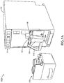
- FIG. 1A illustrates a system 100 that includes a beverage maker 102 and a decaling module 200 for descaling the beverage maker 102.
- the beverage maker 102 may be any device that produces a beverage.
- the beverage maker 102 illustrated in FIG. 1A is an espresso machine.
- the beverage maker 102 may be a cappuccino maker, a latte maker, a coffee maker, a hot water tap, a soda fountain, a slushie machine, or the like.
- the beverage maker 102 includes a user interface 104 (e.g., one or more buttons, switches, dials, knobs, a LCD/LED display, a touch panel, a touchscreen display, or any combination thereof) that can be used to turn on/off the beverage maker 102 and/or adjust one or more parameters of the beverage maker 102 (e.g., water temperature, brew intensity). Additionally, the user interface 104 may be configured to receive a user input to select an operational mode (e.g., brew mode, cleaning mode, descaling mode, etc.). For example, the user interface 104 may be used to initiate a descaling mode or sequence.
- an operational mode e.g., brew mode, cleaning mode, descaling mode, etc.
- the beverage maker 102 also includes at least one brew head 108 (e.g., an espresso brew head, sometimes referred to as a "group head” or “brew group”).
- the brew head 108 may extend from the chassis of the beverage maker, or as shown in FIG. 1A , the brew head 108 may be disposed within a brew cavity 106.
- the brew cavity 106 is a recessed region within the chassis of the beverage maker 102 where the dispensed beverage (e.g., espresso) may be delivered into a cup or other receptacle.
- the brew head 108 may include any device known in the art used for dispensing a beverage, including, but not limited to, a spout, spigot, nozzle, valve, tap, or the like.
- the beverage maker 102 may include two or more brew heads 108 (e.g., two brew heads 108, as shown in FIG. 1A ) or a brew head 108 with multiple output ports (e.g., multiple nozzles, spouts, or the like).
- the beverage maker 102 further includes a retaining arm 110.
- the retaining arm 110 may be configured to secure and/or stabilize liquid holding containers (e.g., mugs, cups, pots, cleaning modules, etc.) within the brew cavity 106.
- the retaining arm 110 may also be configured to retain brew cups, pods, or other devices that can hold espresso pods, coffee bags, or the like.
- the retaining arm 110 may be of any shape or form known in the art to secure and stabilize liquid holding containers.
- the retaining arm may also be configured as a safety device.
- the retaining arm may be configured to prevent the beverage maker 102 from operating when the retaining arm is not engaged to secure and stabilize the liquid holding containers.
- the descaling module 200 is configured to be coupled to one or more brew heads 108. In some embodiments, the descaling module 200 can be at least partially disposed within the brew cavity 106 of the beverage maker 102.
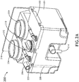
- the descaling module 200 is illustrated in FIGS. 2A through 2C , according to one or more embodiments of this disclosure.
- the descaling module 200 includes a container 201 configured to hold a descaling fluid.
- the container 201 may be of any shape.
- the container 201 may be a cube, a cuboid, rectangular prism, a sphere, a spheroid, cylinder, or any other three-dimensional shape.
- the container 201 may be constructed of any type of material known to hold a liquid.
- the container 201 may be constructed of plastic, glass, metal, carbon fiber, or any other substance commonly used to construct a container 201.
- the descaling fluid may include any descaling solution known in the art.
- the descaling solution may include, but is not limited to, citric acid, acetic acid, hydrochloric acid, or the like.
- the descaling module 200 may include a removably attached lid 202 that covers the container 201.
- the lid 202 may be constructed of any material known in the art to cover a container 201, including, but not limited to, plastic, rubber, glass, metal, carbon fiber.
- the lid 202 may be further configured to be latched onto the container 201 using any technique known in the art for latching a lid 202 to a container 201, including, but not limited to, cam locks, slam latches, spring latches, pressure-retaining rings, snap-fit joints, or other fasteners (e.g., screws, bolts, etc.).
- the lid 202 may also be configured to be permanently affixed to the container 201. In some embodiments, the lid 202 may be permanently attached to one side of the container 201 by a hinge.
- the container 201 may include a top surface that encloses or substantially encloses the container 201.
- the descaling module 200 further includes a fill port 210 that allows descaling fluid to be dispensed into the descaling module 200 in preparation for the descaling process.
- the fill port 210 can also allow fluid to be poured out of the descaling module 200 when the descaling process has been completed.
- the fill port 210 may be positioned on any part of the descaling module 200 (e.g., top, sides, or bottom). In some embodiments, the fill port 210 is located on the top (e.g., on the lid 202 or top surface) of the descaling module 200, allowing descaling fluid to be poured directly into the descaling module 200 when the descaling module 200 is in an upright position.
- the fill port 210 can be closed with lid 212 (e.g., screw-on or snap-on lid), plug, stopper, valve or any other device that seals the fill port 210 to maintain pressure within the container 201 and/or prevent fluid from leaking out of the container 201 when the descaling module 200 is in use.
- lid 212 e.g., screw-on or snap-on lid
- the descaling module 200 includes at least one input port 204 that is configured to couple with a respective brew head 108.
- the descaling module 200 may include two or more input ports 204 (e.g., two input ports 204, as illustrated in FIG. 2A ) that are configured to couple with respective brew heads 108 and/or respective brew head ports (e.g., nozzles, spouts, or the like).
- the coupling of the brew head 108 to the input port 204 may be achieved by a coupler attached to the input port 204 of the descaling module 200.
- the coupler may be a separate component.
- the coupling of the input port 204 to the brew head 108 may be accomplished by any coupler known in the art, including, but not limited to, an adaptor, a flange, a union, a reducer, or a sleeve.
- the descaling module 200 also includes at least one output port 206 that is configured to flow the descaling fluid through a fluid path of the beverage maker 102 when pressurized fluid enters the container 201 through the one or more input ports 204 and forces the descaling fluid through the output port 206.
- the beverage maker 102 may dispense water and/or descaling fluid from the one or more brew heads 108 into the container 201 through the one or more input ports 204, causing at least some of the fluid in the container 201 to be ejected through the output port 206, and into a fluid path of the beverage maker 102.
- This circular (or closed loop) flow allows the descaling fluid to cycle through the fluid path (e.g., reservoir, tubes, pipes, etc.) of the beverage maker 102.
- the output port 206 is configured to couple with the steam outlet (e.g., steam port, froth port, froth module adaptor) of the beverage maker 102.
- the output port 206 of the descaling module 200 may be coupled to the fluid path of the beverage maker 102 via the steam outlet.
- the output port 206 may be configured to flow the descaling fluid into the beverage maker 102 through another port that leads to the reservoir of the beverage maker 102 and/or through a tube or line that directly couples the output port 206 to the reservoir and/or any other portion of the fluid path.
- the steam outlet of the beverage maker 102 may include an input element that is configured to couple with the output port 206 of the descaling module 200.
- the input element may include, but is not limited to, a froth module adaptor, a steam wand, a steam wand adaptor, a shuttle end of a shuttle valve assembly, or any other input element that may couple to the output port 206 of the descaling module 200.
- a coupler may be configured to attach to the output port 206 of the descaling module 200 and couple with the steam outlet and/or the input element (e.g., froth module adaptor, a steam wand, a steam wand adaptor, a shuttle end of a shuttle valve assembly) of the beverage maker 102.
- the coupler may be a stand-alone component.
- the coupling of the output port of the descaling module 200 to the steam outlet of the beverage maker 102 may be accomplished by any coupler known in the art, including, but not limited to, an adaptor, a flange, a union, a reducer, or a sleeve.
- the descaling module 200 includes a pickup tube 208 that extends from the output port 206 into the container 201.
- the pickup tube 208 may be configured to direct descaling fluid through the output port 206 of the container when descaling fluid enters the descaling module 200 through the input port 204.
- the pickup tube 208 may be configured to extend from the output port 206 to near the bottom of the descaling module 200, allowing efficient flow of descaling fluid into the pickup tube 208 while helping prevent or reduce air flow from the output port 206 into the fluid path of the beverage maker 102.
- the descaling module 200 further includes a safety valve 214.
- the safety valve 214 may permit the release of fluid from the descaling module 200 if the pressure within the descaling module 200 exceeds a threshold pressure level.
- the pressure within the descaling module 200 may be raised if the pumps of the beverage maker 102 run fluid through the brew heads into the descaling module 200 faster than the ability of the descaling fluid to exit through the output port 206. Any constriction or blockage the fluid path of the beverage maker 102 and/or the descaling module 200 can also lead to an increase of pressure within the descaling module 200.
- the safety valve 214 may reduce the risk of explosion due to excessive pressure in the container 201 by releasing fluid from the descaling module 200 when the pressure in the container 201 exceeds a threshold pressure level.
- the safety valve 214 may be positioned on any part of the descaling module 200 (e.g., top, sides, or bottom). In some embodiments, the safety valve 214 allows fluid to be released into drip tray or drain when the descaling module 200 is installed within the beverage maker 102.
- the safety valve 214 may be of any type of safety valve known in the art, including, but not limited to, a spring-loaded pressure-relief valve, balanced bellows relief valve, or a pilot operated relief valve.
- the safety valve 214 may be coupled to a tube configured to direct fluid released form the safety valve 214 away from the descaling module 200.
- High pressure in the descaling module 200 may cause the safety valve 214 installed on the descaling module 200 to engage, causing descaling fluid to be released out of the descaling module 200.
- the tube may protect the environment from the descaling fluid by directing the fluid away from the beverage maker 102.
- the tube is made of a semi-transparent or fully transparent material. The transparent nature of the tubing allows fluid escaping the safety valve 214 to be observed, indicating a problem with the descaling module 200 and/or the descaling cycle.
- the tube coupled to the safety valve 214 may redirect the fluid to a drip tray or drain. Alternatively, the tube may direct the fluid to a waste container.
- the descaling module 200 further includes a shield 216 configured to redirect fluid that has escaped the descaling module 200 towards the beverage maker 102.
- the connections between the input ports 204 and the brew heads 108, as well as the connections between the input ports 206 and the steam outlets, are points along the system 100 that are at risk for leakage.
- the descaling fluid is pressurized and may be heated. Leakage of descaling fluid at the input ports 204 and output ports 206 could spray and burn a person near the beverage maker 102 or cause damage to the nearby environment.
- the shield 216 may be configured to block and redirect any escaping fluid toward the beverage maker 102 (and away from a potential user standing in front of the beverage maker 102 during the descaling process).
- the shield 216 may be configured as a raised lip along the top side of the descaling module 200, running parallel to, and nearly flush with, the top of the entrance to the brew cavity 106 as the descaling module 200 is installed into the brew cavity 106 of the beverage maker 102.
- multiple shields 216 may be arranged around the one or more input ports 204 and/or output ports 206.
- the shield 216 may be of any design known in the art to divert escaping fluids. Therefore, the above description should not be regarded as limiting.
- the descaling module 200 may further include a handle 218 extending from the container 201 or lid 202.
- the handle 218 may allow the descaling module 200 to be efficiently and safely inserted into the brew cavity 106 of the beverage maker 102.
- the handle 218 may be of any type known in the art to install and remove a module (e.g., pull handle).
- the handle 218 may be positioned on any part of the descaling module 200 (e.g., top, sides, or bottom). In some embodiments, the handle 218 is located on the side of the descaling module 200 facing away from the beverage maker 102 when the descaling module 200 has been inserted into the brew cavity 106 of the beverage maker 102.
- the handle 218 is positioned horizontally relative to the upright position of the descaling module 200. In embodiments, the handle 218 may be positioned vertically relative to the upright position of the descaling module 200. In some embodiments, the handle 218 may be positioned neither horizontally nor vertically relative to the upright position of the descaling module 200.
- the descaling module 200 further includes a retaining tab 220 configured to releasably lock the descaling module 200 into an operating position.
- a retaining tab 220 configured to releasably lock the descaling module 200 into an operating position.
- Proper alignment of the descaling module 200 in the brew cavity 106 of the beverage maker 102 is important in order for the descaling fluid to become pressurized during the descaling process and not escape the descaling module 200 through the input ports 204 or output ports 206.
- the retaining tab 220 may be configured to engage when the descaling module 200 is in the correct operational position (e.g., the input port 204 is correctly coupled with the brew heads 108 and the output ports 206 are correctly coupled with the steam port).
- the retaining tab 220 can be disengaged by providing pressure by a finger or thumb upon the retaining tab 220 while the descaling module 200 is being pulled from the brew cavity 106.
- the retaining tab 220 is of any type that can guide and hold the descaling module 200 in the correct operational position.
- the retaining tab 220 may be a component of a snap-fit joint, a tongue and groove joint, or any other type of retaining tab 220 known in the art.
- the descaling module 200 further includes a pump configured to pump descaling fluid through the output port 206 of the descaling module 200 into the beverage maker 102.
- a pump allows the descaling module 200 to operate and descale the beverage maker 102 while the beverage maker 102 is turned off.
- the pump may force descaling fluid through the output port 206 of the descaling module 200 into beverage maker, wherein the now pressurized and circulating descaling fluid reenters the descaling module 200 through the input port 204 via the brew heads 108 of the beverage maker 102.
- the pump may be of any type of pump used in the art to move fluids, including, but not limited to, a positive displacement pump (e.g., peristaltic pump, gear pump, plunger pump), an impulse pump or a velocity pump.
- the pump may be located at any place within the descaling module 200 that allows pumping of descaling fluid into the beverage maker 102.
- the pump may be battery powered.
- the battery may be of any type of battery known in the art for powering a pump (e.g., zinc-carbon, alkaline, nickel-cadmium, nickel-zinc, nickel metal anhydride, lithium ion).
- the pump may be powered by an external AC or DC power source.
- the descaling module 200 further includes a detectable element 222 that allow the beverage maker 102 to detect a presence of the descaling module 200 when the descaling module 200 is disposed within the brew cavity 106 and/or coupled to the one or more brew heads 108 of the beverage maker 102.
- the detectable element 222 may be positioned on any part of the descaling module 200 (e.g., top, sides, or bottom). In some embodiments, the detectable element 222 is located on the side of the descaling module 200 that faces the beverage maker 102 when the descaling module 200 is disposed within the brew cavity 106 and/or coupled to the one or more brew heads 108.
- the beverage maker 102 may include a detector 308 that is configured to sense the detectable element 222 when the descaling module 200 is disposed within the brew cavity 106 and/or coupled to the one or more brew heads 108 of the beverage maker 102.
- the detector 308 may be positioned on any part of the beverage maker 102 (e.g., top, sides, within the brew cavity 106).
- the detector 308 is disposed within the brew cavity 106 and/or located on or near the one or more brew heads 108 so that the detector 308 is brought in proximity to the detectable element 222 of the descaling module 200 when the descaling module 200 is disposed within the brew cavity 106 and/or coupled to the one or more brew heads 108.
- the detectable element 222 of the descaling module 200 and the detector 308 of the beverage maker 102 may employ any sensor protocol commonly used in the art for identifying swappable components.
- the detectable element 222 may be a magnet
- the detector 308 may be a reed switch that is transitioned from a first state (e.g., open) to a second state (e.g., closed) when the magnet is brought in proximity to the read switch.
- the detectable element 222 may be an optical pattern or a recognizable feature (e.g., a barcode, QR code, or the like)
- the detector 308 may be an optical sensor (e.g., barcode reader, camera, scanner, or the like).
- the detectable element 222 may be a radio-frequency identification (RFID) tag, and the detector 308 may be an RDIF reader. It is noted herein that other detection technologies known in art can be used to identify a swappable component. Therefore, the above description should not be regarded as limiting.
- the detectable element 222 may include a combination of detectable elements (e.g., magnet, RFID tag, optical pattern, etc.), and similarly the detector 308 may include a combination of detector types (e.g., optical/image sensor, RFID reader, reed switch, etc.) to allow for more robust detection and/or identification of the descaling module 200 by the beverage maker 102.
- RFID radio-frequency identification
- the beverage maker 102 further includes a controller 300 communicatively coupled to the user interface 104, detector 308, and other electronic/electromechanical components (e.g., sensors, pumps, actuators, etc.) of the beverage maker 102.
- the controller 300 may include at least one processor 302, memory 304, and a communication interface 306.
- the processor 302 is configured to provide processing functionality for at least the controller 300 and can include any number of processors, micro-controllers, circuitry, field programmable gate array (FPGA) or other processing systems, and resident or external memory for storing data, executable code, and other information accessed or generated by the controller 300.
- the processor 302 is configured to execute one or more software programs embodied in a non-transitory computer readable medium (e.g., memory 304) that implement techniques described herein.
- the processor 302 is not limited by the materials from which it is formed or the processing mechanisms employed therein and, as such, can be implemented via semiconductor(s) and/or transistors (e.g., using electronic integrated circuit (IC) components), and so forth.
- the memory 304 can be an example of tangible, computer-readable storage medium that provides storage functionality to store various data and/or program code associated with operation of the controller 300/processor 302, such as software programs and/or code segments, or other data to instruct the processor 302, and possibly other components of the controller 300, to perform the functionality described herein.
- the memory 304 can store data, such as a program of instructions for operating the controller 300, including its components (e.g., processor 302, communication interface 306, etc.), and so forth.
- a single memory 304 is described, a wide variety of types and combinations of memory (e.g., tangible, non-transitory memory) can be employed.
- the memory 304 can be integral with the processor 302, can comprise stand-alone memory, or can be a combination of both. Some examples of the memory 304 can include removable and non-removable memory components, such as random-access memory (RAM), read-only memory (ROM), flash memory (e.g., a secure digital (SD) memory card, a mini-SD memory card, and/or a micro-SD memory card), solid-state drive (SSD) memory, magnetic memory, optical memory, universal serial bus (USB) memory devices, hard disk memory, external memory, and so forth.
- RAM random-access memory
- ROM read-only memory
- flash memory e.g., a secure digital (SD) memory card, a mini-SD memory card, and/or a micro-SD memory card
- SSD solid-state drive
- magnetic memory magnetic memory
- optical memory optical memory
- USB universal serial bus
- the communication interface 306 can be operatively configured to communicate with components of the controller 300.
- the communication interface 306 can be configured to retrieve data from the processor 302 or other devices (e.g., user interface 104, detector 308, etc.), transmit data for storage in the memory 304, retrieve data from storage in the memory 304, and so forth.
- the communication interface 306 can also be communicatively coupled with the processor 302 to facilitate data transfer between components of the controller 300 and the processor 302. It should be noted that while the communication interface 306 is described as a component of the controller 300, one or more components of the communication interface 306 can be implemented as external components communicatively coupled to the controller 300 via a wired and/or wireless connection.
- the controller 300 can also include and/or connect to one or more input/output (I/O) devices.
- the communication interface 306 includes or is coupled to a transmitter, receiver, transceiver, physical connection interface, or any combination thereof.
- the controller 300 may be configured to detect the presence and/or identity of the descaling module 200 when the detector 308 senses the detectable element 222.
- the controller 300 may be configured to determine whether the descaling module 200 is correctly disposed within the brew cavity 106 and/or correctly coupled to the one or more brew heads 108 of the beverage maker 102 when the detector 308 senses the detectable element 222.
- the controller 300 is configured to detect the identity of the descaling module 200 based on detection and/or communication with the detectable element 222.
- the controller 300 may be configured to differentiate between different types of modules (e.g., descaling module 200, cleaning module, different beverage modules, etc.) based on data acquired by the detector 308 from the detectable element 222.
- the detector 308 may collect identification data in the form of a barcode, QR code, image recognition, RFID, a particular positioning of the detectable element 222, any combination thereof, and so forth.
- the controller 300 may also be configured to determine other information (e.g., descaling fluid type, amount of descaling fluid, etc.) associated with the descaling module 200 based on data collected from the detectable element 222 by the detector 308.
- the controller 300 may be configured to present a notification via the user interface 104, indicating that the descaling module 200 has been detected and/or that the beverage maker 102 is ready to be descaled.
- the controller 300 is configured to hide or prevent access to a descaling option via the user interface 104 when the descaling module 200 is not detected. Conversely, the controller 300 can present the descaling option via the user interface 104 when the descaling module 200 is detected.
- the controller 300 is further configured to automatically place the beverage maker 102 in a descaling mode of operation when the descaling module 200 is detected, such that other operations (e.g., brewing) are hidden via the user interface 104 and/or deactivated.
Landscapes
- Engineering & Computer Science (AREA)
- Food Science & Technology (AREA)
- Apparatus For Making Beverages (AREA)
Abstract
Description
- Beverage makers (e.g., espresso machines) can brew espresso by forcing hot water through a concentrated mass of ground coffee. The resulting liquid is collected and consumed. The path of water through beverage maker's reservoir, tubing, filters, and so forth are typically constructed of metal (e.g., brass, stainless steel), rubber, and/or plastic. Minerals naturally occurring in water (e.g., calcium, magnesium) are often deposited onto inner surfaces of beverage maker components in the form of limescale. Deposits of limescale may shorten the lifespan of beverage maker components. In addition, limescale is difficult to remove, is unsightly, and can affect the taste of the espresso.
- One method of preventing the buildup of limescale is through regular cleaning of the beverage maker with a descaling solution (e.g., a low pH solution). In a descaling cleaning, descaling fluids are circulated through the beverage maker for a set period of time. Once used, the descaling solution is removed from the beverage maker and discarded. The beverage maker is then rinsed with water before being put back into use.
- Beverage makers on aircraft may require descaling on a regular basis. Descaling a beverage maker on an aircraft can be difficult, as the beverage maker unit may need to be removed, partially removed, and/or partially disassembled in order to access the ports needed for adding the descaling solutions. These methods are laborious and time consuming. Consequently, there is a need for improved descaling processes and/or devices.
- A descaling module is disclosed. In one or more embodiments, the descaling module includes a container configured to receive a descaling fluid. The descaling module further includes at least one input port and at least one output port. The input port is configured to couple the container to a respective brew head of the beverage maker. The output port is configured to flow the descaling fluid through a fluid path of the beverage maker when pressurized fluid enters the container through the input port and forces the descaling fluid through the output port.
- In some embodiments of the descaling module, the descaling module further includes a detectable element configured to indicate at least one of a presence of the descaling module or an identity of the descaling module.
- In some embodiments of the descaling module, the descaling module further includes a fill port for dispensing the descaling fluid into the container.
- In some embodiments of the descaling module, the descaling module further includes at least one pickup tube coupled to the output port and extending into the container. The pickup tube may be configured to direct the descaling fluid through the output port of the container when pressurized fluid enters the container.
- In some embodiments of the descaling module, the descaling module further includes a handle on an external surface of the container.
- In some embodiments of the descaling module, the descaling module further includes a shield disposed adjacent to the at least one input port and configured to redirect fluid escaping from the input port or the output port toward the beverage maker.
- In some embodiments of the descaling module, the descaling module further includes at least one retaining tab configured to releasably secure the descaling module in an operating position when the descaling module is disposed within a brew cavity of the beverage maker.
- In some embodiments of the descaling module, the descaling module further includes a safety valve.
- In some embodiments of the descaling module, the safety valve is coupled to an at least partially transparent tube configured to direct fluid released from the safety valve away from the descaling module.
- In some embodiments of the descaling module, the descaling module further includes a pump configured to pump the descaling fluid from the container into the beverage maker.
- A system is also disclosed. In one or more embodiments, the system includes a beverage maker and a descaling module configured to be at least partially disposed within a brew cavity of the beverage maker. The descaling module includes a container configured to receive a descaling fluid. The descaling module further includes at least one input port and at least one output port. The input port is configured to couple the container to a respective brew head of the beverage maker. The output port is configured to flow the descaling fluid through a fluid path of the beverage maker when pressurized fluid enters the container through the input port and forces the descaling fluid through the output port.
- In some embodiments of the system, the descaling module further includes a detectable element configured to indicate at least one of a presence of the descaling module or an identity of the descaling module.
- In some embodiments of the system, the beverage maker further includes a detector that is configured to sense the detectable element of the descaling module.
- In some embodiments of the system, the beverage maker includes a controller communicatively coupled to the detector. The controller is further configured to detect the presence and/or the identity of the descaling module when the detector senses the detectable element of the descaling module.
- In some embodiments of the system, the descaling module further includes a fill port for dispensing the descaling fluid into the container.
- In some embodiments of the system, the descaling module further includes at least one pickup tube coupled to the output port and extending into the container. The pickup tube may be configured to direct the descaling fluid through the output port of the container when pressurized fluid enters the container.
- In some embodiments of the system, the descaling module further includes a handle on an external surface of the container.
- In some embodiments of the system, the descaling module further includes a shield disposed adjacent to the input port and configured to redirect fluid escaping from the input port or the output port toward the beverage maker.
- In some embodiments of the system, the descaling module further includes at least one retaining tab configured to releasably secure the descaling module in an operating position when the descaling module is disposed within the brew cavity of the beverage maker.
- In some embodiments of the system, the descaling module includes a safety valve.
- In some embodiments of the system, the safety valve of the descaling module is coupled to an at least partially transparent tube configured to direct fluid released from the safety valve away from the descaling module.
- In some embodiments of the system, the descaling module further includes a pump configured to pump the descaling fluid from the container into the beverage maker.
- This Summary is provided solely as an introduction to subject matter that is fully described in the Detailed Description and Drawings. The Summary should not be considered to describe essential features nor be used to determine the scope of the Claims. Moreover, it is to be understood that both the foregoing Summary and the following Detailed Description are example and explanatory only and are not necessarily restrictive of the subject matter claimed.
- The detailed description is described with reference to the accompanying figures. The use of the same reference numbers in different instances in the description and the figures may indicate similar or identical items. Various embodiments or examples ("examples") of the present disclosure are disclosed in the following detailed description and the accompanying drawings. The drawings are not necessarily to scale. In general, operations of disclosed processes may be performed in an arbitrary order, unless otherwise provided in the claims. In the drawings:
-
FIG. 1A is a perspective view of a beverage maker and a descaling module, in accordance with one or more embodiments of this disclosure; -
FIG. 1B is a perspective view of a descaling module inserted into a beverage maker, in accordance with one or more embodiments of this disclosure; -
FIG. 2A is a perspective rear view of a descaling module, in accordance with one or more embodiments of this disclosure; -
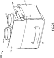
FIG. 2B is perspective front view of a descaling module, in accordance with one or more embodiments of this disclosure; -
FIG. 2C is a top view of a descaling module, in accordance with one or more embodiments of this disclosure; and -
FIG. 3 is a block diagram illustrating a control system for a beverage maker, in accordance with one or more embodiments of this disclosure. - Before explaining one or more embodiments of the disclosure in detail, it is to be understood that the embodiments are not limited in their application to the details of construction and the arrangement of the components or steps or methodologies set forth in the following description or illustrated in the drawings. In the following detailed description of embodiments, numerous specific details may be set forth in order to provide a more thorough understanding of the disclosure. However, it will be apparent to one of ordinary skill in the art having the benefit of the instant disclosure that the embodiments disclosed herein may be practiced without some of these specific details. In other instances, well-known features may not be described in detail to avoid unnecessarily complicating the instant disclosure.
- As used herein a letter following a reference numeral is intended to reference an embodiment of the feature or element that may be similar, but not necessarily identical, to a previously described element or feature bearing the same reference numeral (e.g., 1, 1a, 1b). Such shorthand notations are used for purposes of convenience only and should not be construed to limit the disclosure in any way unless expressly stated to the contrary.
- Further, unless expressly stated to the contrary, "or" refers to an inclusive or and not to an exclusive or. For example, a condition A or B is satisfied by anyone of the following: A is true (or present) and B is false (or not present), A is false (or not present) and B is true (or present), and both A and B are true (or present).
- In addition, use of "a" or "an" may be employed to describe elements and components of embodiments disclosed herein. This is done merely for convenience and "a" and "an" are intended to include "one" or "at least one," and the singular also includes the plural unless it is obvious that it is meant otherwise.
- Finally, as used herein any reference to "one embodiment" or "some embodiments" means that a particular element, feature, structure, or characteristic described in connection with the embodiment is included in at least one embodiment disclosed herein. The appearances of the phrase "in some embodiments" in various places in the specification are not necessarily all referring to the same embodiment, and embodiments may include one or more of the features expressly described or inherently present herein, or any combination of sub-combination of two or more such features, along with any other features which may not necessarily be expressly described or inherently present in the instant disclosure.
- A descaling module for a beverage maker is disclosed. Beverage makers on aircraft may require descaling on a regular basis. Descaling a beverage maker on an aircraft can be difficult, as the beverage maker unit may need to be removed, partially removed, and/or partially disassembled in order to access the ports needed for adding the descaling solutions. These methods are laborious and time consuming. On the other hand, the disclosed descaling module can be inserted into a beverage maker for a more streamlined and automated descaling process.
-
FIG. 1A illustrates asystem 100 that includes abeverage maker 102 and adecaling module 200 for descaling thebeverage maker 102. Thebeverage maker 102 may be any device that produces a beverage. For example, thebeverage maker 102 illustrated inFIG. 1A is an espresso machine. However, in other embodiments, thebeverage maker 102 may be a cappuccino maker, a latte maker, a coffee maker, a hot water tap, a soda fountain, a slushie machine, or the like. - The
beverage maker 102 includes a user interface 104 (e.g., one or more buttons, switches, dials, knobs, a LCD/LED display, a touch panel, a touchscreen display, or any combination thereof) that can be used to turn on/off thebeverage maker 102 and/or adjust one or more parameters of the beverage maker 102 (e.g., water temperature, brew intensity). Additionally, theuser interface 104 may be configured to receive a user input to select an operational mode (e.g., brew mode, cleaning mode, descaling mode, etc.). For example, theuser interface 104 may be used to initiate a descaling mode or sequence. - The
beverage maker 102 also includes at least one brew head 108 (e.g., an espresso brew head, sometimes referred to as a "group head" or "brew group"). Thebrew head 108 may extend from the chassis of the beverage maker, or as shown inFIG. 1A , thebrew head 108 may be disposed within abrew cavity 106. In some embodiments, thebrew cavity 106 is a recessed region within the chassis of thebeverage maker 102 where the dispensed beverage (e.g., espresso) may be delivered into a cup or other receptacle. In embodiments, thebrew head 108 may include any device known in the art used for dispensing a beverage, including, but not limited to, a spout, spigot, nozzle, valve, tap, or the like. Furthermore, thebeverage maker 102 may include two or more brew heads 108 (e.g., two brew heads 108, as shown inFIG. 1A ) or abrew head 108 with multiple output ports (e.g., multiple nozzles, spouts, or the like). - In some embodiments, the
beverage maker 102 further includes a retainingarm 110. When engaged, the retainingarm 110 may be configured to secure and/or stabilize liquid holding containers (e.g., mugs, cups, pots, cleaning modules, etc.) within thebrew cavity 106. The retainingarm 110 may also be configured to retain brew cups, pods, or other devices that can hold espresso pods, coffee bags, or the like. The retainingarm 110 may be of any shape or form known in the art to secure and stabilize liquid holding containers. In embodiments, the retaining arm may also be configured as a safety device. For example, the retaining arm may be configured to prevent thebeverage maker 102 from operating when the retaining arm is not engaged to secure and stabilize the liquid holding containers. - As shown in
FIG. 1B , thedescaling module 200 is configured to be coupled to one or more brew heads 108. In some embodiments, thedescaling module 200 can be at least partially disposed within thebrew cavity 106 of thebeverage maker 102. Thedescaling module 200 is illustrated inFIGS. 2A through 2C , according to one or more embodiments of this disclosure. - Referring to
FIGS. 2A and2B , thedescaling module 200 includes acontainer 201 configured to hold a descaling fluid. Thecontainer 201 may be of any shape. For example, thecontainer 201 may be a cube, a cuboid, rectangular prism, a sphere, a spheroid, cylinder, or any other three-dimensional shape. Thecontainer 201 may be constructed of any type of material known to hold a liquid. For instance, thecontainer 201 may be constructed of plastic, glass, metal, carbon fiber, or any other substance commonly used to construct acontainer 201. In embodiments, the descaling fluid may include any descaling solution known in the art. For example, the descaling solution may include, but is not limited to, citric acid, acetic acid, hydrochloric acid, or the like. - The
descaling module 200 may include a removably attachedlid 202 that covers thecontainer 201. Thelid 202 may be constructed of any material known in the art to cover acontainer 201, including, but not limited to, plastic, rubber, glass, metal, carbon fiber. Thelid 202 may be further configured to be latched onto thecontainer 201 using any technique known in the art for latching alid 202 to acontainer 201, including, but not limited to, cam locks, slam latches, spring latches, pressure-retaining rings, snap-fit joints, or other fasteners (e.g., screws, bolts, etc.). Thelid 202 may also be configured to be permanently affixed to thecontainer 201. In some embodiments, thelid 202 may be permanently attached to one side of thecontainer 201 by a hinge. Alternatively, instead of thelid 202, thecontainer 201 may include a top surface that encloses or substantially encloses thecontainer 201. - In some embodiments, the
descaling module 200 further includes afill port 210 that allows descaling fluid to be dispensed into thedescaling module 200 in preparation for the descaling process. Thefill port 210 can also allow fluid to be poured out of thedescaling module 200 when the descaling process has been completed. Thefill port 210 may be positioned on any part of the descaling module 200 (e.g., top, sides, or bottom). In some embodiments, thefill port 210 is located on the top (e.g., on thelid 202 or top surface) of thedescaling module 200, allowing descaling fluid to be poured directly into thedescaling module 200 when thedescaling module 200 is in an upright position. In some embodiments, thefill port 210 can be closed with lid 212 (e.g., screw-on or snap-on lid), plug, stopper, valve or any other device that seals thefill port 210 to maintain pressure within thecontainer 201 and/or prevent fluid from leaking out of thecontainer 201 when thedescaling module 200 is in use. - The
descaling module 200 includes at least oneinput port 204 that is configured to couple with arespective brew head 108. In some embodiments, thedescaling module 200 may include two or more input ports 204 (e.g., twoinput ports 204, as illustrated inFIG. 2A ) that are configured to couple with respective brew heads 108 and/or respective brew head ports (e.g., nozzles, spouts, or the like). In embodiments, the coupling of thebrew head 108 to theinput port 204 may be achieved by a coupler attached to theinput port 204 of thedescaling module 200. Alternatively, the coupler may be a separate component. The coupling of theinput port 204 to thebrew head 108 may be accomplished by any coupler known in the art, including, but not limited to, an adaptor, a flange, a union, a reducer, or a sleeve. - The
descaling module 200 also includes at least oneoutput port 206 that is configured to flow the descaling fluid through a fluid path of thebeverage maker 102 when pressurized fluid enters thecontainer 201 through the one ormore input ports 204 and forces the descaling fluid through theoutput port 206. For example, thebeverage maker 102 may dispense water and/or descaling fluid from the one or more brew heads 108 into thecontainer 201 through the one ormore input ports 204, causing at least some of the fluid in thecontainer 201 to be ejected through theoutput port 206, and into a fluid path of thebeverage maker 102. This circular (or closed loop) flow allows the descaling fluid to cycle through the fluid path (e.g., reservoir, tubes, pipes, etc.) of thebeverage maker 102. In some embodiments, theoutput port 206 is configured to couple with the steam outlet (e.g., steam port, froth port, froth module adaptor) of thebeverage maker 102. In this regard, theoutput port 206 of thedescaling module 200 may be coupled to the fluid path of thebeverage maker 102 via the steam outlet. In other embodiments, theoutput port 206 may be configured to flow the descaling fluid into thebeverage maker 102 through another port that leads to the reservoir of thebeverage maker 102 and/or through a tube or line that directly couples theoutput port 206 to the reservoir and/or any other portion of the fluid path. - In some embodiments, the steam outlet of the
beverage maker 102 may include an input element that is configured to couple with theoutput port 206 of thedescaling module 200. For example, the input element may include, but is not limited to, a froth module adaptor, a steam wand, a steam wand adaptor, a shuttle end of a shuttle valve assembly, or any other input element that may couple to theoutput port 206 of thedescaling module 200. In some embodiments, a coupler may be configured to attach to theoutput port 206 of thedescaling module 200 and couple with the steam outlet and/or the input element (e.g., froth module adaptor, a steam wand, a steam wand adaptor, a shuttle end of a shuttle valve assembly) of thebeverage maker 102. Alternatively, the coupler may be a stand-alone component. The coupling of the output port of thedescaling module 200 to the steam outlet of thebeverage maker 102 may be accomplished by any coupler known in the art, including, but not limited to, an adaptor, a flange, a union, a reducer, or a sleeve. - In some embodiments, the
descaling module 200 includes apickup tube 208 that extends from theoutput port 206 into thecontainer 201. Thepickup tube 208 may be configured to direct descaling fluid through theoutput port 206 of the container when descaling fluid enters thedescaling module 200 through theinput port 204. Thepickup tube 208 may be configured to extend from theoutput port 206 to near the bottom of thedescaling module 200, allowing efficient flow of descaling fluid into thepickup tube 208 while helping prevent or reduce air flow from theoutput port 206 into the fluid path of thebeverage maker 102. - In some embodiments, the
descaling module 200 further includes asafety valve 214. Thesafety valve 214 may permit the release of fluid from thedescaling module 200 if the pressure within thedescaling module 200 exceeds a threshold pressure level. In thesystem 100, the pressure within thedescaling module 200 may be raised if the pumps of thebeverage maker 102 run fluid through the brew heads into thedescaling module 200 faster than the ability of the descaling fluid to exit through theoutput port 206. Any constriction or blockage the fluid path of thebeverage maker 102 and/or thedescaling module 200 can also lead to an increase of pressure within thedescaling module 200. Thesafety valve 214 may reduce the risk of explosion due to excessive pressure in thecontainer 201 by releasing fluid from thedescaling module 200 when the pressure in thecontainer 201 exceeds a threshold pressure level. - The
safety valve 214 may be positioned on any part of the descaling module 200 (e.g., top, sides, or bottom). In some embodiments, thesafety valve 214 allows fluid to be released into drip tray or drain when thedescaling module 200 is installed within thebeverage maker 102. Thesafety valve 214 may be of any type of safety valve known in the art, including, but not limited to, a spring-loaded pressure-relief valve, balanced bellows relief valve, or a pilot operated relief valve. - In embodiments, the
safety valve 214 may be coupled to a tube configured to direct fluid released form thesafety valve 214 away from thedescaling module 200. High pressure in thedescaling module 200 may cause thesafety valve 214 installed on thedescaling module 200 to engage, causing descaling fluid to be released out of thedescaling module 200. The tube may protect the environment from the descaling fluid by directing the fluid away from thebeverage maker 102. In embodiments, the tube is made of a semi-transparent or fully transparent material. The transparent nature of the tubing allows fluid escaping thesafety valve 214 to be observed, indicating a problem with thedescaling module 200 and/or the descaling cycle. In some embodiments, the tube coupled to thesafety valve 214 may redirect the fluid to a drip tray or drain. Alternatively, the tube may direct the fluid to a waste container. - In some embodiments, the
descaling module 200 further includes ashield 216 configured to redirect fluid that has escaped thedescaling module 200 towards thebeverage maker 102. The connections between theinput ports 204 and the brew heads 108, as well as the connections between theinput ports 206 and the steam outlets, are points along thesystem 100 that are at risk for leakage. During the descaling process, the descaling fluid is pressurized and may be heated. Leakage of descaling fluid at theinput ports 204 andoutput ports 206 could spray and burn a person near thebeverage maker 102 or cause damage to the nearby environment. Theshield 216 may be configured to block and redirect any escaping fluid toward the beverage maker 102 (and away from a potential user standing in front of thebeverage maker 102 during the descaling process). Referring toFIG. 1B , in embodiments, theshield 216 may be configured as a raised lip along the top side of thedescaling module 200, running parallel to, and nearly flush with, the top of the entrance to thebrew cavity 106 as thedescaling module 200 is installed into thebrew cavity 106 of thebeverage maker 102. Alternatively,multiple shields 216 may be arranged around the one ormore input ports 204 and/oroutput ports 206. Theshield 216 may be of any design known in the art to divert escaping fluids. Therefore, the above description should not be regarded as limiting. - As shown in
FIGS. 2B and2C , thedescaling module 200 may further include ahandle 218 extending from thecontainer 201 orlid 202. Thehandle 218 may allow thedescaling module 200 to be efficiently and safely inserted into thebrew cavity 106 of thebeverage maker 102. Thehandle 218 may be of any type known in the art to install and remove a module (e.g., pull handle). Thehandle 218 may be positioned on any part of the descaling module 200 (e.g., top, sides, or bottom). In some embodiments, thehandle 218 is located on the side of thedescaling module 200 facing away from thebeverage maker 102 when thedescaling module 200 has been inserted into thebrew cavity 106 of thebeverage maker 102. In embodiments, thehandle 218 is positioned horizontally relative to the upright position of thedescaling module 200. In embodiments, thehandle 218 may be positioned vertically relative to the upright position of thedescaling module 200. In some embodiments, thehandle 218 may be positioned neither horizontally nor vertically relative to the upright position of thedescaling module 200. - In some embodiments, the
descaling module 200 further includes aretaining tab 220 configured to releasably lock thedescaling module 200 into an operating position. Proper alignment of thedescaling module 200 in thebrew cavity 106 of thebeverage maker 102 is important in order for the descaling fluid to become pressurized during the descaling process and not escape thedescaling module 200 through theinput ports 204 oroutput ports 206. When thedescaling module 200 is being installed into thebrew cavity 106, the retainingtab 220 may be configured to engage when thedescaling module 200 is in the correct operational position (e.g., theinput port 204 is correctly coupled with the brew heads 108 and theoutput ports 206 are correctly coupled with the steam port). In embodiments, the retainingtab 220 can be disengaged by providing pressure by a finger or thumb upon theretaining tab 220 while thedescaling module 200 is being pulled from thebrew cavity 106. In embodiments, the retainingtab 220 is of any type that can guide and hold thedescaling module 200 in the correct operational position. For instance, the retainingtab 220 may be a component of a snap-fit joint, a tongue and groove joint, or any other type of retainingtab 220 known in the art. - In some embodiments, the
descaling module 200 further includes a pump configured to pump descaling fluid through theoutput port 206 of thedescaling module 200 into thebeverage maker 102. Use of a pump allows thedescaling module 200 to operate and descale thebeverage maker 102 while thebeverage maker 102 is turned off. In embodiments, the pump may force descaling fluid through theoutput port 206 of thedescaling module 200 into beverage maker, wherein the now pressurized and circulating descaling fluid reenters thedescaling module 200 through theinput port 204 via the brew heads 108 of thebeverage maker 102. The pump may be of any type of pump used in the art to move fluids, including, but not limited to, a positive displacement pump (e.g., peristaltic pump, gear pump, plunger pump), an impulse pump or a velocity pump. The pump may be located at any place within thedescaling module 200 that allows pumping of descaling fluid into thebeverage maker 102. In some embodiments, the pump may be battery powered. The battery may be of any type of battery known in the art for powering a pump (e.g., zinc-carbon, alkaline, nickel-cadmium, nickel-zinc, nickel metal anhydride, lithium ion). Alternatively, the pump may be powered by an external AC or DC power source. - In some embodiments, the
descaling module 200 further includes adetectable element 222 that allow thebeverage maker 102 to detect a presence of thedescaling module 200 when thedescaling module 200 is disposed within thebrew cavity 106 and/or coupled to the one or more brew heads 108 of thebeverage maker 102. Thedetectable element 222 may be positioned on any part of the descaling module 200 (e.g., top, sides, or bottom). In some embodiments, thedetectable element 222 is located on the side of thedescaling module 200 that faces thebeverage maker 102 when thedescaling module 200 is disposed within thebrew cavity 106 and/or coupled to the one or more brew heads 108. - As shown in
FIG. 3 , thebeverage maker 102 may include adetector 308 that is configured to sense thedetectable element 222 when thedescaling module 200 is disposed within thebrew cavity 106 and/or coupled to the one or more brew heads 108 of thebeverage maker 102. Thedetector 308 may be positioned on any part of the beverage maker 102 (e.g., top, sides, within the brew cavity 106). In some embodiments, thedetector 308 is disposed within thebrew cavity 106 and/or located on or near the one or more brew heads 108 so that thedetector 308 is brought in proximity to thedetectable element 222 of thedescaling module 200 when thedescaling module 200 is disposed within thebrew cavity 106 and/or coupled to the one or more brew heads 108. - The
detectable element 222 of thedescaling module 200 and thedetector 308 of thebeverage maker 102 may employ any sensor protocol commonly used in the art for identifying swappable components. For example, in an embodiment, thedetectable element 222 may be a magnet, and thedetector 308 may be a reed switch that is transitioned from a first state (e.g., open) to a second state (e.g., closed) when the magnet is brought in proximity to the read switch. In another embodiment, thedetectable element 222 may be an optical pattern or a recognizable feature (e.g., a barcode, QR code, or the like), and thedetector 308 may be an optical sensor (e.g., barcode reader, camera, scanner, or the like). In yet another embodiment, thedetectable element 222 may be a radio-frequency identification (RFID) tag, and thedetector 308 may be an RDIF reader. It is noted herein that other detection technologies known in art can be used to identify a swappable component. Therefore, the above description should not be regarded as limiting. Furthermore, in some embodiments, thedetectable element 222 may include a combination of detectable elements (e.g., magnet, RFID tag, optical pattern, etc.), and similarly thedetector 308 may include a combination of detector types (e.g., optical/image sensor, RFID reader, reed switch, etc.) to allow for more robust detection and/or identification of thedescaling module 200 by thebeverage maker 102. - In embodiments, the
beverage maker 102 further includes acontroller 300 communicatively coupled to theuser interface 104,detector 308, and other electronic/electromechanical components (e.g., sensors, pumps, actuators, etc.) of thebeverage maker 102. Thecontroller 300 may include at least oneprocessor 302,memory 304, and acommunication interface 306. - The
processor 302 is configured to provide processing functionality for at least thecontroller 300 and can include any number of processors, micro-controllers, circuitry, field programmable gate array (FPGA) or other processing systems, and resident or external memory for storing data, executable code, and other information accessed or generated by thecontroller 300. Theprocessor 302 is configured to execute one or more software programs embodied in a non-transitory computer readable medium (e.g., memory 304) that implement techniques described herein. Theprocessor 302 is not limited by the materials from which it is formed or the processing mechanisms employed therein and, as such, can be implemented via semiconductor(s) and/or transistors (e.g., using electronic integrated circuit (IC) components), and so forth. - The
memory 304 can be an example of tangible, computer-readable storage medium that provides storage functionality to store various data and/or program code associated with operation of thecontroller 300/processor 302, such as software programs and/or code segments, or other data to instruct theprocessor 302, and possibly other components of thecontroller 300, to perform the functionality described herein. Thus, thememory 304 can store data, such as a program of instructions for operating thecontroller 300, including its components (e.g.,processor 302,communication interface 306, etc.), and so forth. It should be noted that while asingle memory 304 is described, a wide variety of types and combinations of memory (e.g., tangible, non-transitory memory) can be employed. Thememory 304 can be integral with theprocessor 302, can comprise stand-alone memory, or can be a combination of both. Some examples of thememory 304 can include removable and non-removable memory components, such as random-access memory (RAM), read-only memory (ROM), flash memory (e.g., a secure digital (SD) memory card, a mini-SD memory card, and/or a micro-SD memory card), solid-state drive (SSD) memory, magnetic memory, optical memory, universal serial bus (USB) memory devices, hard disk memory, external memory, and so forth. - The
communication interface 306 can be operatively configured to communicate with components of thecontroller 300. For example, thecommunication interface 306 can be configured to retrieve data from theprocessor 302 or other devices (e.g.,user interface 104,detector 308, etc.), transmit data for storage in thememory 304, retrieve data from storage in thememory 304, and so forth. Thecommunication interface 306 can also be communicatively coupled with theprocessor 302 to facilitate data transfer between components of thecontroller 300 and theprocessor 302. It should be noted that while thecommunication interface 306 is described as a component of thecontroller 300, one or more components of thecommunication interface 306 can be implemented as external components communicatively coupled to thecontroller 300 via a wired and/or wireless connection. Thecontroller 300 can also include and/or connect to one or more input/output (I/O) devices. In embodiments, thecommunication interface 306 includes or is coupled to a transmitter, receiver, transceiver, physical connection interface, or any combination thereof. - In embodiments, the
controller 300 may be configured to detect the presence and/or identity of thedescaling module 200 when thedetector 308 senses thedetectable element 222. Thecontroller 300 may be configured to determine whether thedescaling module 200 is correctly disposed within thebrew cavity 106 and/or correctly coupled to the one or more brew heads 108 of thebeverage maker 102 when thedetector 308 senses thedetectable element 222. In some embodiments, thecontroller 300 is configured to detect the identity of thedescaling module 200 based on detection and/or communication with thedetectable element 222. For example, thecontroller 300 may be configured to differentiate between different types of modules (e.g.,descaling module 200, cleaning module, different beverage modules, etc.) based on data acquired by thedetector 308 from thedetectable element 222. For example, thedetector 308 may collect identification data in the form of a barcode, QR code, image recognition, RFID, a particular positioning of thedetectable element 222, any combination thereof, and so forth. In some embodiments, thecontroller 300 may also be configured to determine other information (e.g., descaling fluid type, amount of descaling fluid, etc.) associated with thedescaling module 200 based on data collected from thedetectable element 222 by thedetector 308. - In response to detecting the presence and/or identity of the
descaling module 200, thecontroller 300 may be configured to present a notification via theuser interface 104, indicating that thedescaling module 200 has been detected and/or that thebeverage maker 102 is ready to be descaled. In some embodiments, thecontroller 300 is configured to hide or prevent access to a descaling option via theuser interface 104 when thedescaling module 200 is not detected. Conversely, thecontroller 300 can present the descaling option via theuser interface 104 when thedescaling module 200 is detected. In some embodiments, thecontroller 300 is further configured to automatically place thebeverage maker 102 in a descaling mode of operation when thedescaling module 200 is detected, such that other operations (e.g., brewing) are hidden via theuser interface 104 and/or deactivated. - Although inventive concepts have been described with reference to the embodiments illustrated in the attached drawing figures, equivalents may be employed and substitutions made herein without departing from the scope of the claims. Components illustrated and described herein are merely examples of a system/device and components that may be used to implement embodiments of the inventive concepts and may be replaced with other devices and components without departing from the scope of the claims. Furthermore, any dimensions, degrees, and/or numerical ranges provided herein are to be understood as non-limiting examples unless otherwise specified in the claims.
Claims (12)
- A descaling module for a beverage maker, comprising:a container (201)configured to receive a descaling fluid;at least one input port (204) configured to couple the container to a respective brew head of the beverage maker; andat least one output port (206) configured to flow the descaling fluid through a fluid path of the beverage maker when pressurized fluid enters the container through the at least one input port and forces the descaling fluid through the at least one output port.
- The descaling module of claim 1, further comprising a detectable element (208) configured to indicate at least one of a presence of the descaling module or an identity of the descaling module.
- The descaling module of claim 1 or 2, further comprising a fill port (210) for dispensing the descaling fluid into the container.
- The descaling module of any preceding claim, further comprising a pickup tube coupled to the at least one output port and extending into the container, wherein the pickup tube is configured to direct the descaling fluid through the at least one output port when the pressurized fluid enters the container.
- The descaling module of any preceding claim, further comprising a handle (218) on an external surface of the container.
- The descaling module of any preceding claim, further comprising a shield (216) disposed adjacent to the at least one input port and configured to redirect fluid escaping from the at least one input port or the at least one output port toward the beverage maker.
- The descaling module of any preceding claim, further comprising at least one retaining tab (220) configured to releasably secure the descaling module in an operating position when the descaling module is disposed within a brew cavity of the beverage maker.
- The descaling module of any preceding claim, further comprising a safety valve (214).
- The descaling module of claim 8, wherein the safety valve is coupled to an at least partially transparent tube configured to direct fluid released from the safety valve away from the descaling module.
- The descaling module of any preceding claim, further comprises a pump configured to pump the descaling fluid from the container into the beverage maker.
- A system, comprising:a beverage maker (102); anda descaling module (200) as claimed in any preceding claim, configured to be at least partially disposed within a brew cavity of the beverage maker.
- The system of claim 11, wherein the beverage maker includes:a detector (308) configured to sense the detectable element of the descaling module; anda controller (300) communicatively coupled to the detector, the controller configured to detect at least one of a presence of the descaling module or an identity of the descaling module when the detector senses the detectable element of the descaling module.
Applications Claiming Priority (1)
| Application Number | Priority Date | Filing Date | Title |
|---|---|---|---|
| US16/409,235 US11202530B2 (en) | 2019-05-10 | 2019-05-10 | Descaling module |
Publications (2)
| Publication Number | Publication Date |
|---|---|
| EP3735877A1 true EP3735877A1 (en) | 2020-11-11 |
| EP3735877B1 EP3735877B1 (en) | 2026-03-04 |
Family
ID=68581449
Family Applications (1)
| Application Number | Title | Priority Date | Filing Date |
|---|---|---|---|
| EP19208924.1A Active EP3735877B1 (en) | 2019-05-10 | 2019-11-13 | Descaling module |
Country Status (2)
| Country | Link |
|---|---|
| US (1) | US11202530B2 (en) |
| EP (1) | EP3735877B1 (en) |
Families Citing this family (5)
| Publication number | Priority date | Publication date | Assignee | Title |
|---|---|---|---|---|
| WO2021255708A1 (en) * | 2020-06-19 | 2021-12-23 | Carimali S.P.A. | Automatic beverage preparation machine with electromagnetic -induction, continuous-flow fluid heater |
| DE102020215847A1 (en) | 2020-12-14 | 2022-06-15 | BSH Hausgeräte GmbH | Device for preparing drinks |
| US12369744B1 (en) | 2024-01-18 | 2025-07-29 | Sharkninja Operating Llc | Preparation of beverage machines for cold beverage brewing |
| WO2025155321A1 (en) | 2024-01-18 | 2025-07-24 | Sharkninja Operating Llc | Suggesting coffee bean grind size for beverage machines |
| US12369741B1 (en) | 2024-01-18 | 2025-07-29 | Sharkninja Operating Llc | Preventing coffee bean grinder jamming |
Citations (3)
| Publication number | Priority date | Publication date | Assignee | Title |
|---|---|---|---|---|
| WO2013188246A2 (en) * | 2012-06-10 | 2013-12-19 | Urnex Inc. | System and method for cleaning a brewing machine |
| US20140060338A1 (en) * | 2012-09-06 | 2014-03-06 | Miele & Cie. Kg | Supply container for a descaling system, automatic beverage maker, and method for descaling an automatic beverage maker |
| US20180192818A1 (en) * | 2017-01-09 | 2018-07-12 | CUP&CINO Kaffeesystem- Vertrieb GmbH & Co. KG | Cleaning System |
Family Cites Families (3)
| Publication number | Priority date | Publication date | Assignee | Title |
|---|---|---|---|---|
| US6889603B2 (en) * | 2002-12-24 | 2005-05-10 | Nestec S.A. | Clean-in-place automated food or beverage dispenser |
| US8511220B2 (en) * | 2009-03-12 | 2013-08-20 | Wal-Mart Stores, Inc. | Cleaning cycle indicator and cleaning process for beverage maker |
| PL3060089T3 (en) * | 2013-10-22 | 2019-12-31 | Koninklijke Philips N.V. | Descaling hot-beverage producing machines |
-
2019
- 2019-05-10 US US16/409,235 patent/US11202530B2/en active Active
- 2019-11-13 EP EP19208924.1A patent/EP3735877B1/en active Active
Patent Citations (3)
| Publication number | Priority date | Publication date | Assignee | Title |
|---|---|---|---|---|
| WO2013188246A2 (en) * | 2012-06-10 | 2013-12-19 | Urnex Inc. | System and method for cleaning a brewing machine |
| US20140060338A1 (en) * | 2012-09-06 | 2014-03-06 | Miele & Cie. Kg | Supply container for a descaling system, automatic beverage maker, and method for descaling an automatic beverage maker |
| US20180192818A1 (en) * | 2017-01-09 | 2018-07-12 | CUP&CINO Kaffeesystem- Vertrieb GmbH & Co. KG | Cleaning System |
Also Published As
| Publication number | Publication date |
|---|---|
| EP3735877B1 (en) | 2026-03-04 |
| US20200352391A1 (en) | 2020-11-12 |
| US11202530B2 (en) | 2021-12-21 |
Similar Documents
| Publication | Publication Date | Title |
|---|---|---|
| EP3735877B1 (en) | Descaling module | |
| TWI682750B (en) | Automatic beverage machine, in particular coffee machine and process to operate such an automatic beverage machine and cartridge for such an automatic beverage machine | |
| JP5437266B2 (en) | System for preparing beverages from ingredients supported by encoded inserts | |
| RU2720564C2 (en) | Beverage preparation device with ergonomic user interface | |
| KR102520404B1 (en) | Cleaning System | |
| EP2906091B1 (en) | Beverage preparation machine with capsule size detection | |
| AU2018283446B2 (en) | Beverage preparation machine with capsule recognition | |
| US20240215755A1 (en) | System for cleaning milk ducts for a machine for preparing beverages | |
| EP3370581B1 (en) | Capsule holder for a beverage preparation machine, beverage preparation machine comprising said capsule holder | |
| US20240180358A1 (en) | System for cleaning milk ducts for a machine for preparing beverages | |
| CN108697261A (en) | Drink draft machine, particularly coffee machine for connecting tap water and tap water external member | |
| CN116268944B (en) | Intelligent beverage machine | |
| EP4099875B1 (en) | Beverage preparation machine with capsule recognition | |
| RU2838215C1 (en) | Beverage preparation device with capsule recognition | |
| CN223799647U (en) | Beverage machine cleaning system and beverage machine equipment | |
| CN211833957U (en) | Instant heating type capsule coffee machine control system and coffee machine | |
| RU2773110C2 (en) | Device for beverage making with capsule identification | |
| EP3628195A1 (en) | Beverage preparation machine with recipient detection | |
| HK1251423B (en) | Cleaning system | |
| HK1128212B (en) | System for preparing a beverage from ingredients supported by an encoded insert |
Legal Events
| Date | Code | Title | Description |
|---|---|---|---|
| PUAI | Public reference made under article 153(3) epc to a published international application that has entered the european phase |
Free format text: ORIGINAL CODE: 0009012 |
|
| STAA | Information on the status of an ep patent application or granted ep patent |
Free format text: STATUS: THE APPLICATION HAS BEEN PUBLISHED |
|
| AK | Designated contracting states |
Kind code of ref document: A1 Designated state(s): AL AT BE BG CH CY CZ DE DK EE ES FI FR GB GR HR HU IE IS IT LI LT LU LV MC MK MT NL NO PL PT RO RS SE SI SK SM TR |
|
| AX | Request for extension of the european patent |
Extension state: BA ME |
|
| STAA | Information on the status of an ep patent application or granted ep patent |
Free format text: STATUS: REQUEST FOR EXAMINATION WAS MADE |
|
| 17P | Request for examination filed |
Effective date: 20210511 |
|
| RBV | Designated contracting states (corrected) |
Designated state(s): AL AT BE BG CH CY CZ DE DK EE ES FI FR GB GR HR HU IE IS IT LI LT LU LV MC MK MT NL NO PL PT RO RS SE SI SK SM TR |
|
| RAP3 | Party data changed (applicant data changed or rights of an application transferred) |
Owner name: B/E AEROSPACE, INC. |
|
| STAA | Information on the status of an ep patent application or granted ep patent |
Free format text: STATUS: EXAMINATION IS IN PROGRESS |
|
| 17Q | First examination report despatched |
Effective date: 20221013 |
|
| P01 | Opt-out of the competence of the unified patent court (upc) registered |
Effective date: 20230922 |
|
| GRAP | Despatch of communication of intention to grant a patent |
Free format text: ORIGINAL CODE: EPIDOSNIGR1 |
|
| STAA | Information on the status of an ep patent application or granted ep patent |
Free format text: STATUS: GRANT OF PATENT IS INTENDED |
|
| INTG | Intention to grant announced |
Effective date: 20250929 |
|
| GRAS | Grant fee paid |
Free format text: ORIGINAL CODE: EPIDOSNIGR3 |
|
| GRAA | (expected) grant |
Free format text: ORIGINAL CODE: 0009210 |
|
| STAA | Information on the status of an ep patent application or granted ep patent |
Free format text: STATUS: THE PATENT HAS BEEN GRANTED |
|
| AK | Designated contracting states |
Kind code of ref document: B1 Designated state(s): AL AT BE BG CH CY CZ DE DK EE ES FI FR GB GR HR HU IE IS IT LI LT LU LV MC MK MT NL NO PL PT RO RS SE SI SK SM TR |
|
| REG | Reference to a national code |
Ref country code: CH Ref legal event code: F10 Free format text: ST27 STATUS EVENT CODE: U-0-0-F10-F00 (AS PROVIDED BY THE NATIONAL OFFICE) Effective date: 20260304 Ref country code: GB Ref legal event code: FG4D |
|
| REG | Reference to a national code |
Ref country code: DE Ref legal event code: R096 Ref document number: 602019082015 Country of ref document: DE |
|
| REG | Reference to a national code |
Ref country code: IE Ref legal event code: FG4D |
|
| PG25 | Lapsed in a contracting state [announced via postgrant information from national office to epo] |
Ref country code: RS Free format text: LAPSE BECAUSE OF FAILURE TO SUBMIT A TRANSLATION OF THE DESCRIPTION OR TO PAY THE FEE WITHIN THE PRESCRIBED TIME-LIMIT Effective date: 20260604 |
|
| PG25 | Lapsed in a contracting state [announced via postgrant information from national office to epo] |
Ref country code: ES Free format text: LAPSE BECAUSE OF FAILURE TO SUBMIT A TRANSLATION OF THE DESCRIPTION OR TO PAY THE FEE WITHIN THE PRESCRIBED TIME-LIMIT Effective date: 20260304 |
|
| REG | Reference to a national code |
Ref country code: NL Ref legal event code: MP Effective date: 20260304 |
|
| PG25 | Lapsed in a contracting state [announced via postgrant information from national office to epo] |
Ref country code: PL Free format text: LAPSE BECAUSE OF FAILURE TO SUBMIT A TRANSLATION OF THE DESCRIPTION OR TO PAY THE FEE WITHIN THE PRESCRIBED TIME-LIMIT Effective date: 20260304 |
|
| PG25 | Lapsed in a contracting state [announced via postgrant information from national office to epo] |
Ref country code: GR Free format text: LAPSE BECAUSE OF FAILURE TO SUBMIT A TRANSLATION OF THE DESCRIPTION OR TO PAY THE FEE WITHIN THE PRESCRIBED TIME-LIMIT Effective date: 20260605 |
|
| REG | Reference to a national code |
Ref country code: LT Ref legal event code: MG9D |
|
| PG25 | Lapsed in a contracting state [announced via postgrant information from national office to epo] |
Ref country code: LT Free format text: LAPSE BECAUSE OF FAILURE TO SUBMIT A TRANSLATION OF THE DESCRIPTION OR TO PAY THE FEE WITHIN THE PRESCRIBED TIME-LIMIT Effective date: 20260304 |
|
| PG25 | Lapsed in a contracting state [announced via postgrant information from national office to epo] |
Ref country code: NO Free format text: LAPSE BECAUSE OF FAILURE TO SUBMIT A TRANSLATION OF THE DESCRIPTION OR TO PAY THE FEE WITHIN THE PRESCRIBED TIME-LIMIT Effective date: 20260604 |
|
| PG25 | Lapsed in a contracting state [announced via postgrant information from national office to epo] |
Ref country code: SE Free format text: LAPSE BECAUSE OF FAILURE TO SUBMIT A TRANSLATION OF THE DESCRIPTION OR TO PAY THE FEE WITHIN THE PRESCRIBED TIME-LIMIT Effective date: 20260304 Ref country code: FI Free format text: LAPSE BECAUSE OF FAILURE TO SUBMIT A TRANSLATION OF THE DESCRIPTION OR TO PAY THE FEE WITHIN THE PRESCRIBED TIME-LIMIT Effective date: 20260304 |
|
| PG25 | Lapsed in a contracting state [announced via postgrant information from national office to epo] |
Ref country code: HR Free format text: LAPSE BECAUSE OF FAILURE TO SUBMIT A TRANSLATION OF THE DESCRIPTION OR TO PAY THE FEE WITHIN THE PRESCRIBED TIME-LIMIT Effective date: 20260304 |
|
| PG25 | Lapsed in a contracting state [announced via postgrant information from national office to epo] |
Ref country code: LV Free format text: LAPSE BECAUSE OF FAILURE TO SUBMIT A TRANSLATION OF THE DESCRIPTION OR TO PAY THE FEE WITHIN THE PRESCRIBED TIME-LIMIT Effective date: 20260304 |
|
| PG25 | Lapsed in a contracting state [announced via postgrant information from national office to epo] |
Ref country code: BG Free format text: LAPSE BECAUSE OF FAILURE TO SUBMIT A TRANSLATION OF THE DESCRIPTION OR TO PAY THE FEE WITHIN THE PRESCRIBED TIME-LIMIT Effective date: 20260304 |