EP3735876A1 - Coffee machine steam relief unit - Google Patents
Coffee machine steam relief unit Download PDFInfo
- Publication number
- EP3735876A1 EP3735876A1 EP19173308.8A EP19173308A EP3735876A1 EP 3735876 A1 EP3735876 A1 EP 3735876A1 EP 19173308 A EP19173308 A EP 19173308A EP 3735876 A1 EP3735876 A1 EP 3735876A1
- Authority
- EP
- European Patent Office
- Prior art keywords
- steam
- relief unit
- steam relief
- water
- filtration element
- Prior art date
- Legal status (The legal status is an assumption and is not a legal conclusion. Google has not performed a legal analysis and makes no representation as to the accuracy of the status listed.)
- Granted
Links
Images

Classifications
-
- A—HUMAN NECESSITIES
- A47—FURNITURE; DOMESTIC ARTICLES OR APPLIANCES; COFFEE MILLS; SPICE MILLS; SUCTION CLEANERS IN GENERAL
- A47J—KITCHEN EQUIPMENT; COFFEE MILLS; SPICE MILLS; APPARATUS FOR MAKING BEVERAGES
- A47J31/00—Apparatus for making beverages
- A47J31/44—Parts or details or accessories of beverage-making apparatus
- A47J31/46—Dispensing spouts, pumps, drain valves or like liquid transporting devices
Definitions
- the present invention relates to coffee machine, particularly to a fully automatic coffee machine having a water tank, a pump, a heating unit, a brewing unit, a drainage system with a drip tray and a steam relief unit for letting off residual steam and water from the heating unit.
- brewing machines have a body with removable water tank for clear water, a pump which delivers the water to the heating source and next to the brewing unit.
- the beverage brewing substance is infused with pressured heated water to produce a brewed beverage.
- After finishing the brewing process there is still a residual steam or water in the coffee machine.
- a control unit of the coffee machine opening said valve and residual steam and water is relieved to the drainage system and finally to the drip tray.
- this is very important to provide a user with safe the coffee maker using, another aspect is to reduce the noise during decompressing the steam which directly affects the user's life and the surrounding environment. For that reason known coffee makers uses different steam reliefs, which are usually made out of plastic housing and inner condensation ribs system. The ribs system causes that the steam flow is sopped and the noise is damped, and the steam is changed into water, which is drained to the drip tray.
- a hot beverage machine includes a heating unit having a fresh water intake.
- a fresh water line supplies fresh water to the fresh water intake of the heating unit.
- a residual fluid line is coupled to the fresh water intake of the heating unit through an on-off valve for conducting fluids to a collection container.
- a device for letting off residual steam and residual water from the heating unit includes a heat-exchanging and heat-storing condenser having a residual line section coupled to the residual fluid line, a fresh water line section coupled into the fresh water line and a heat storing medium that is connected for conducting heat between the residual line section and the fresh water line section.
- the rotary support is installed on the capsule supporting plate in an opening and closing mode;
- the handle is in matched connection with the rotary support;
- the pressure relief assembly is installed on the capsule supporting plate;
- the valve core is arranged at one end of the pressure relief valve assembly;
- the shifting rod is arranged on the handle;
- the limitation groove is formed in the rotary support;
- the shifting rod is in matched connection with the limitation groove; when the shifting rod moves to an appropriate angle along with rotation of the handle, the rotary support rotates to be in a close state; when the shifting rod continues to rotate, one end of the handle is abut against the valve core to enable the pressure relief valve assembly to be in a sealing state.
- Document CN201905741 discloses the pressure relief device of a coffee machine which comprises a heating pot body which is arranged in a coffee machine body and can be used for preparing steam and hot water, wherein a pressure relief buffering and silencing device is connected into a pressure relief channel on the coffee machine body, is communicated with the pressure relief channel, and comprises a pressure relief box and a pressure relief box cover matched with the pressure relief box.
- the pressure relief buffering and silencing device is additionally arranged, so that the mixture of steam exhausted from the pressure relief channel and water is led into the pressure relief box, buffered by a first filter core and a second filter core in the pressure relief box and stored in the pressure relief box; when a large amount of mixture of steam and water is accumulated at the upper port of a drain pipe, the mixture is drained from the upper port of the drain pipe; and when the pressure relief work is stopped, remaining accumulated water in the pressure relief box is drained from the lower port of the drain pipe of the pressure relief box, so that the mixture of the steam and water rapidly discharged during pressure relief is discharged after being buffered and silenced.
- Known pressure relieving devices comprise complicated structure what generates high production costs. Moreover complicated structure of it can cause increasing failure rate of the device.
- the objective of the present invention is to provide a steam relief unit, and more particular a steam relief unit for coffee machine, which is convenient to use, safety and simple in structure, also cost effective in production and assembling, and improves stability of the decompression process and reduces the noise of decompressed a steam/water, improving the comfort.
- a steam relief unit for a coffee machine especially for fully automatic coffee machine comprising a closed housing which defines a steam relief unit chamber.
- the steam relief unit also comprises at least one water and/or steam inlet port and at least one the water outlet port, and they are each formed on the housing and communicated with the steam relief unit chamber.
- a water or/and steam flow path extends, the water or steam which is delivered into the inlet port passes the steam relief unit chamber and a filtration element along said water or steam flow path towards the outlet port.
- the filtration element is arranged inside the steam relief unit chamber in between the inlet port and the outlet port, and fills the steam relief unit chamber in at least 50% of it volume, and the filtration element covers in whole the flow path in at least one cross section of the flow path.
- the coffee machine especially fully automatic coffee machine usually comprises a body with removable the water tank for a fresh water connected to a water tank port and a pump which delivers the water to a heating unit and next to a brewing unit or a discharge nozzle for a hot water, through a multi-way valve.
- the beverage brewing substance is infused with a pressured heated water to produce a brewed beverage.
- the excess water formed in the brewing process is collected in a drip tray placed in the lower portion of the coffee machine.
- the filtration element fills the whole volume of the steam relief unit chamber.
- the full filling the volume of the steam relief unit chamber by the filtration element additionally improves the reduction of the noise, the temperature is improved.
- the steam relief unit chamber is equipped with the filtration element which is made of porous material. Porous structure of the filtration element slowing down the speed of stream of the residual water or steam incoming into the steam relief unit chamber through the inlet port and limits the noise.
- the filtration element also cool down the steam and/or hot water, and the steam is condensed to water.
- the steam relief unit comprises the filtration element which is made of foam.
- the foam is impregnated with a silicone oil or lubricant. Therefore a water passes easier through the filtration element and the foam is prevented from formatting of mold.
- the steam relief unit has the steam relief unit chamber provided with a sloping bottom surface communicated with the outlet port and placed at the lower point of the sloping bottom surface.
- the water that passed through the filtration element is collected on the sloping bottom surface, and because of the slope of the bottom portion, the passing water is gravitationally flow towards the outlet port.
- the steam relief unit is made of plastic and consist of an upper housing and a lower housing which are permanently connected together. Both parts can be made in the process of injection molding that's lowering the costs of producing, then after placing the filtration element inside the steam relief unit chamber, they can be permanently connected by gluing or welding, or latched mutually.
- the steam relief unit is provided with at least one protrusion for fixing it inside in coffee machine.
- the steam relief unit is placed inside the coffee machine, therefore is really important to place it in right position to allow discharge the water from the steam relief unit chamber through the outlet port into the drip tray.
- the coffee machine has the steam relief unit is placed above the drip tray of the coffee machine and is communicated with drip tray therefore the water can be discharged from the steam relief unit directly to the drip tray.
- the coffee machine includes the steam relief unit that is fluidly connected through the inlet port to a heating unit via the valve.
- the said valve is responsible for controlling a water and/or a steam flow towards the steam relief unit.
- the valve it can be utilized a multi-way valve, namely one of the section the said multi-way valve.
- the above mentioned structure of the steam relieve unit which directs the whole amount of the residual water or steam, which comes to the inlet port passes through the filtration element.
- the large volume of the filtration element which fills at least 50% of the steam relieve unit chamber, causes that stability of the decompression process, the reduction the noise, and reduction temperature of a decompressed steam/water is achieved.
- improved structure of the steam and shape comprising a flat surfaces allows producing it by injection molding, what decreases production costs.
- a steam relief unit 1 in accordance with the preferred embodiment of the present invention comprises a closed housing 3, composed of an upper housing 31 and a lower housing 32 with and an outlet port 5, and defining a steam relief unit chamber 2 (not shown on this figure).
- the lower housing 32 has a sloping bottom surface 13 (not shown on this figure), inclined towards the outlet port 5. Therefore a water that collected on the bottom surface 13 flows down into the outlet port 5 by gravity.
- the steam relief unit 1 is placed inside a body of the coffee machine above a drip tray (not shown on this figure) both fluidly communicated, therefore the water that leaves the steam relief unit 1 goes directly to the drip tray.
- the drip tray has the form of a removable drawer, and collected water can be easily removed.
- the steam relief unit 1 is formed in the shape of truncated prism with substantially flat a bottom and a top portion provided with sloping portion, and vertically arranged four side walls.
- the top portion of the housing 3 is equipped with two inlet ports 9 which are fluidly connected to a steam relief unit chamber 2 (not shown on this figure) and a first of them is connected to the heating unit 7 via a multiway valve 8 by a fluid duct 10, and a second inlet port 9 is connected to a pump 6 and further connected to the water tank port 14.
- the steam relief unit chamber 2 is equipped with a filtration element 11 (not shown on this figure). After the coffee has been made the water or steam still residues in a heating unit 7 due to be closed by a multi-way valve 8. Therefore in the next step of functioning of the coffee machine, the multi-way valve 8 opens connection between the heating unit 7 and the steam relief unit 1 via fluid ducts 10.
- Fluid ducts 10 are made as flexible pipe resistant to the pressure and the temperature at least 150 degrees Celsius. The flexibility of the fluid ducts 10 gives more possibilities of arranging the interior of the coffee machine.
- the steam relief unit 1 in accordance with the preferred embodiment of the present invention comprises the closed housing 3, composed of the upper housing 31 and the lower housing 32 with and the outlet port 5, and defining the steam relief unit chamber 2.
- the lower housing 32 has the sloping bottom surface 13 (not shown on this figure), inclined towards the outlet port 5. Therefore a water that collected on the bottom surface 13 flows down into the outlet port 5 by gravity.
- the steam relief unit 1 is placed inside the body of the coffee machine above a drip tray (not shown on this figure) both fluidly connected, therefore the water that leaves the steam relief unit 1 goes to the drip tray.
- the drip tray has the form of a removable drawer, and collected water can be easily removed. Both portions of the housing 3 are permanently connected together along rims 12.
- the rims 12 are formed circumferentially along the opened edges of the upper housing 31 and the lower housing 32. Said rims 12 stiffen the housing 3 and strengthen the connection between the upper housing 31 and the lower housing 32.
- the steam relief unit 1 is formed in the shape of truncated prism with substantially flat a bottom and a top portion provided with sloping portion, and vertically arranged four side walls.
- the upper housing 31 is in a form of a truncated rectangular dome with recess, as a portion of the steam relief unit chamber 2, for receiving the filtration element 11 which is made of a silicone impregnated foam.
- the filtration element 11 fills the full volume of the steam relief unit chamber 2.
- the top portion of the housing 3 is equipped with two inlet ports 9 which are fluidly connected to the steam relief unit chamber 2, and a first of them is connected to the heating unit 7 via a multiway valve 8 by a fluid duct 10, and a second inlet port 9 is connected to a pump 6, which is further connected to a water tank port 14 to deliver fresh water to the system.
- the filtration element 11 covers the whole cross-section of a flow path which extends from the inlet port 9 towards the outlet port 5. Therefore the full amount of the water or steam delivered into the steam relief unit chamber 2, goes through the filtration element 11. After the coffee has been made the water or the steam still residues in a heating unit 7 due to closing by a multi-way valve 8.
- the multi-way valve 8 opens connection between the heating unit 7 and the steam relief unit 1 via fluid ducts 10, therefore the residual a water or/and a steam can flow to the steam relief unit 1.
- the fluid ducts 10 are made as flexible pipe resistant to the pressure and the temperature at least 150 degrees Celsius. The flexibility of the fluid ducts 10 gives more possibilities of arranging the interior of the coffee machine.
- the steam relief unit 1 in accordance with the preferred embodiment of the present invention comprises the closed housing 3, composed of the upper housing 31 and the lower housing 32 defining the steam relief unit chamber 2.
- the steam relief unit 1 is placed inside the body of the coffee machine above the drip tray (not shown on this figure) both fluidly communicated, therefore the water that leaves the steam relief unit 1 goes to the drip tray.
- the drip tray has the form of a removable drawer, then collected water can be easily removed.
- Both portions of the housing 3 are permanently connected together along the rims 12.
- the rims 12 are formed circumferentially along the opened edges of the upper housing 31 and the lower housing 32. Said rims 12 stiffen the housing 3 and strengthen the connection between the upper housing 31 and the lower housing 32.
- the steam relief unit 1 is formed in the shape of truncated prism with substantially flat a bottom portion and a top portion partially provided with sloping portion, and vertically arranged four side walls.
- the upper housing 31 is in a form of the gagated rectangular dome with the recess, as a portion of the steam relief unit chamber 2 for receiving the filtration element 11.
- the lower housing 32 is in the form of the shallow tray or pan with slopping the bottom surface 13, inclined towards the outlet port 5. Therefore a water that collected on the bottom surface 13 flows down into the outlet port 5 by gravity.
- the filtration element 11 is made of a silicone impregnated foam and fills the full volume of the steam relief unit chamber 2.
- the top portion of the housing 3 is equipped with two inlet ports 9 which are fluidly communicated with the steam relief unit chamber 2, and the first of them is connected to the heating unit 7 via a multiway valve 8 by a fluid duct 10, and the second one inlet port 9 is connected to the pump 6 by an another fluid duct 10.
- the filtration element 11 covers the whole cross-section of the flow path which extends from the inlet port 9 towards the outlet port 5. Therefore the full amount of the water and/or steam delivered into the steam relief unit chamber 2, goes through the filtration element 11. After the coffee has been made the water or the steam still residues in the heating unit 7 due to be closed by a multi-way valve 8.
- the multi-way valve 8 opens connection between the heating unit 7 and the steam relief unit 1 via fluid ducts 10, in that way the residual a water or/and a steam can flow to the steam relief unit 1.
- Fluid ducts 10 are made as flexible pipe resistant to the pressure and the temperature at least 150 degrees Celsius. The flexibility of the fluid ducts 10 gives more possibilities of arranging the interior of the coffee machine.
Landscapes
- Engineering & Computer Science (AREA)
- Food Science & Technology (AREA)
- Apparatus For Making Beverages (AREA)
Abstract
Description
- The present invention relates to coffee machine, particularly to a fully automatic coffee machine having a water tank, a pump, a heating unit, a brewing unit, a drainage system with a drip tray and a steam relief unit for letting off residual steam and water from the heating unit.
- Automatic coffee brewing devices are known in the state of the art and commonly used in restaurants, catering organizations and other high volume food production institutions. Typically, brewing machines have a body with removable water tank for clear water, a pump which delivers the water to the heating source and next to the brewing unit. The beverage brewing substance is infused with pressured heated water to produce a brewed beverage. After finishing the brewing process, there is still a residual steam or water in the coffee machine. With known fluid systems in coffee machines and other hot beverage machines, it is generally desirable to remove any residual water in the heating unit which remains after the coffee extraction or the hot water release. Usually it is achieved by an additional solenoid valve or there is used section of a multi-way valve. After finishing process of brewing or other process with using hot water or steam, a control unit of the coffee machine opening said valve and residual steam and water is relieved to the drainage system and finally to the drip tray. Because of the high pressure and high temperature of the residual steam and water this is very important to provide a user with safe the coffee maker using, another aspect is to reduce the noise during decompressing the steam which directly affects the user's life and the surrounding environment. For that reason known coffee makers uses different steam reliefs, which are usually made out of plastic housing and inner condensation ribs system. The ribs system causes that the steam flow is sopped and the noise is damped, and the steam is changed into water, which is drained to the drip tray.
- Document
US2004177760 (A1 ) discloses a hot beverage machine includes a heating unit having a fresh water intake. A fresh water line supplies fresh water to the fresh water intake of the heating unit. A residual fluid line is coupled to the fresh water intake of the heating unit through an on-off valve for conducting fluids to a collection container. A device for letting off residual steam and residual water from the heating unit includes a heat-exchanging and heat-storing condenser having a residual line section coupled to the residual fluid line, a fresh water line section coupled into the fresh water line and a heat storing medium that is connected for conducting heat between the residual line section and the fresh water line section. - Document
CN103565278 (B ) discloses a pressure relieving device for a coffee machine comprises a capsule supporting plate, a rotary support, a handle, a pressure relief valve assembly, a valve core, a shifting rod and a limitation groove; the rotary support is installed on the capsule supporting plate in an opening and closing mode; the handle is in matched connection with the rotary support; the pressure relief assembly is installed on the capsule supporting plate; the valve core is arranged at one end of the pressure relief valve assembly; the shifting rod is arranged on the handle; the limitation groove is formed in the rotary support; the shifting rod is in matched connection with the limitation groove; when the shifting rod moves to an appropriate angle along with rotation of the handle, the rotary support rotates to be in a close state; when the shifting rod continues to rotate, one end of the handle is abut against the valve core to enable the pressure relief valve assembly to be in a sealing state. - Document
CN201905741 (U ) discloses the pressure relief device of a coffee machine which comprises a heating pot body which is arranged in a coffee machine body and can be used for preparing steam and hot water, wherein a pressure relief buffering and silencing device is connected into a pressure relief channel on the coffee machine body, is communicated with the pressure relief channel, and comprises a pressure relief box and a pressure relief box cover matched with the pressure relief box. In the utility model, the pressure relief buffering and silencing device is additionally arranged, so that the mixture of steam exhausted from the pressure relief channel and water is led into the pressure relief box, buffered by a first filter core and a second filter core in the pressure relief box and stored in the pressure relief box; when a large amount of mixture of steam and water is accumulated at the upper port of a drain pipe, the mixture is drained from the upper port of the drain pipe; and when the pressure relief work is stopped, remaining accumulated water in the pressure relief box is drained from the lower port of the drain pipe of the pressure relief box, so that the mixture of the steam and water rapidly discharged during pressure relief is discharged after being buffered and silenced. - Known pressure relieving devices comprise complicated structure what generates high production costs. Moreover complicated structure of it can cause increasing failure rate of the device.
- The objective of the present invention is to provide a steam relief unit, and more particular a steam relief unit for coffee machine, which is convenient to use, safety and simple in structure, also cost effective in production and assembling, and improves stability of the decompression process and reduces the noise of decompressed a steam/water, improving the comfort.
- In accordance with the present invention, there is provided a steam relief unit for a coffee machine especially for fully automatic coffee machine, comprising a closed housing which defines a steam relief unit chamber. The steam relief unit also comprises at least one water and/or steam inlet port and at least one the water outlet port, and they are each formed on the housing and communicated with the steam relief unit chamber. In between the inlet port and the water outlet port of the housing, inside the steam relief unit chamber a water or/and steam flow path extends, the water or steam which is delivered into the inlet port passes the steam relief unit chamber and a filtration element along said water or steam flow path towards the outlet port. The filtration element is arranged inside the steam relief unit chamber in between the inlet port and the outlet port, and fills the steam relief unit chamber in at least 50% of it volume, and the filtration element covers in whole the flow path in at least one cross section of the flow path. The coffee machine especially fully automatic coffee machine usually comprises a body with removable the water tank for a fresh water connected to a water tank port and a pump which delivers the water to a heating unit and next to a brewing unit or a discharge nozzle for a hot water, through a multi-way valve. The beverage brewing substance is infused with a pressured heated water to produce a brewed beverage. The excess water formed in the brewing process is collected in a drip tray placed in the lower portion of the coffee machine.
- Because of the above mentioned structure of the steam relieve unit, a whole amount of the residual in system of the coffee machine water or steam, which come to the inlet port passes through the filtration element, and the large volume of the filtration element which fills at least 50% of the steam relieve unit chamber, causes that stability of the decompression process and reduction the noise, and reduction temperature of decompressed the steam/water is improved. Also improved structure of the steam and shape comprises a flat surfaces allows producing it by injection molding, what decreases production costs.
- In the preferred embodiment the filtration element fills the whole volume of the steam relief unit chamber. The full filling the volume of the steam relief unit chamber by the filtration element additionally improves the reduction of the noise, the temperature is improved.
- Advantageously, the steam relief unit chamber is equipped with the filtration element which is made of porous material. Porous structure of the filtration element slowing down the speed of stream of the residual water or steam incoming into the steam relief unit chamber through the inlet port and limits the noise. The filtration element also cool down the steam and/or hot water, and the steam is condensed to water.
- In the preferred embodiment the steam relief unit comprises the filtration element which is made of foam. Utilizing the foam as the filtration element, radically decreases cost of producing, and is easy to applicate in the steam relief unit chamber, because of resilience of the foam and therefore easy to attach therein. Advantageously the foam is impregnated with a silicone oil or lubricant. Therefore a water passes easier through the filtration element and the foam is prevented from formatting of mold.
- Advantageously, the steam relief unit has the steam relief unit chamber provided with a sloping bottom surface communicated with the outlet port and placed at the lower point of the sloping bottom surface. The water that passed through the filtration element is collected on the sloping bottom surface, and because of the slope of the bottom portion, the passing water is gravitationally flow towards the outlet port.
- In the preferred embodiment the steam relief unit is made of plastic and consist of an upper housing and a lower housing which are permanently connected together. Both parts can be made in the process of injection molding that's lowering the costs of producing, then after placing the filtration element inside the steam relief unit chamber, they can be permanently connected by gluing or welding, or latched mutually.
- Advantageously, the steam relief unit is provided with at least one protrusion for fixing it inside in coffee machine. The steam relief unit is placed inside the coffee machine, therefore is really important to place it in right position to allow discharge the water from the steam relief unit chamber through the outlet port into the drip tray.
- Advantageously the coffee machine has the steam relief unit is placed above the drip tray of the coffee machine and is communicated with drip tray therefore the water can be discharged from the steam relief unit directly to the drip tray.
- Advantageously the coffee machine includes the steam relief unit that is fluidly connected through the inlet port to a heating unit via the valve. The said valve is responsible for controlling a water and/or a steam flow towards the steam relief unit. As the valve it can be utilized a multi-way valve, namely one of the section the said multi-way valve. After the coffee has been made, the residual compressed the steam or/and water still exists in the system e.g. in a heating unit of the coffee machine. The pressure coming from the residual steam and/or water maintained in the system for a long time is harmful to system components, especially for seals, therefore it is so important to release the residual steam or water from the system.
- Advantageously, the above mentioned structure of the steam relieve unit, which directs the whole amount of the residual water or steam, which comes to the inlet port passes through the filtration element. The large volume of the filtration element which fills at least 50% of the steam relieve unit chamber, causes that stability of the decompression process, the reduction the noise, and reduction temperature of a decompressed steam/water is achieved. Also improved structure of the steam and shape comprising a flat surfaces allows producing it by injection molding, what decreases production costs.
- Further benefits and advantages of the present invention will become apparent after a careful reading of the detailed description with appropriate reference to the accompanying drawings.
- In the drawings:
-
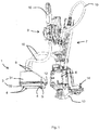
Fig. 1 is a perspective view of a steam relief unit in accordance with the preferred embodiment of the present invention. -
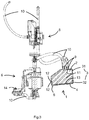
Fig. 2 is an exploded perspective view of the steam relief unit as shown inFig. 1 . -
Fig. 3 is cross-sectional operational view of the steam relief unit as shown inFig. 1 . - Referring to the
Fig. 1 asteam relief unit 1 in accordance with the preferred embodiment of the present invention comprises a closedhousing 3, composed of anupper housing 31 and alower housing 32 with and anoutlet port 5, and defining a steam relief unit chamber 2 (not shown on this figure). Thelower housing 32 has a sloping bottom surface 13 (not shown on this figure), inclined towards theoutlet port 5. Therefore a water that collected on thebottom surface 13 flows down into theoutlet port 5 by gravity. Thesteam relief unit 1 is placed inside a body of the coffee machine above a drip tray (not shown on this figure) both fluidly communicated, therefore the water that leaves thesteam relief unit 1 goes directly to the drip tray. Usually the drip tray has the form of a removable drawer, and collected water can be easily removed. Both portions of thehousing 3 are permanently connected together alongrims 12, which are formed circumferentially along the opened edges of theupper housing 31 and thelower housing 32. Said rims 12 stiffen thehousing 3 and strengthen the connection between theupper housing 31 and thelower housing 32. Thesteam relief unit 1 is formed in the shape of truncated prism with substantially flat a bottom and a top portion provided with sloping portion, and vertically arranged four side walls. The top portion of thehousing 3 is equipped with twoinlet ports 9 which are fluidly connected to a steam relief unit chamber 2 (not shown on this figure) and a first of them is connected to theheating unit 7 via amultiway valve 8 by afluid duct 10, and asecond inlet port 9 is connected to apump 6 and further connected to thewater tank port 14. The steamrelief unit chamber 2 is equipped with a filtration element 11 (not shown on this figure). After the coffee has been made the water or steam still residues in aheating unit 7 due to be closed by amulti-way valve 8. Therefore in the next step of functioning of the coffee machine, themulti-way valve 8 opens connection between theheating unit 7 and thesteam relief unit 1 viafluid ducts 10.Fluid ducts 10 are made as flexible pipe resistant to the pressure and the temperature at least 150 degrees Celsius. The flexibility of thefluid ducts 10 gives more possibilities of arranging the interior of the coffee machine. - Referring to the
Fig. 2 thesteam relief unit 1 in accordance with the preferred embodiment of the present invention comprises theclosed housing 3, composed of theupper housing 31 and thelower housing 32 with and theoutlet port 5, and defining the steamrelief unit chamber 2. Thelower housing 32 has the sloping bottom surface 13 (not shown on this figure), inclined towards theoutlet port 5. Therefore a water that collected on thebottom surface 13 flows down into theoutlet port 5 by gravity. Thesteam relief unit 1 is placed inside the body of the coffee machine above a drip tray (not shown on this figure) both fluidly connected, therefore the water that leaves thesteam relief unit 1 goes to the drip tray. Usually the drip tray has the form of a removable drawer, and collected water can be easily removed. Both portions of thehousing 3 are permanently connected together along rims 12. Therims 12 are formed circumferentially along the opened edges of theupper housing 31 and thelower housing 32. Said rims 12 stiffen thehousing 3 and strengthen the connection between theupper housing 31 and thelower housing 32. Thesteam relief unit 1 is formed in the shape of truncated prism with substantially flat a bottom and a top portion provided with sloping portion, and vertically arranged four side walls. Theupper housing 31 is in a form of a truncated rectangular dome with recess, as a portion of the steamrelief unit chamber 2, for receiving thefiltration element 11 which is made of a silicone impregnated foam. Thefiltration element 11 fills the full volume of the steamrelief unit chamber 2. The top portion of thehousing 3 is equipped with twoinlet ports 9 which are fluidly connected to the steamrelief unit chamber 2, and a first of them is connected to theheating unit 7 via amultiway valve 8 by afluid duct 10, and asecond inlet port 9 is connected to apump 6, which is further connected to awater tank port 14 to deliver fresh water to the system. In any cross section through the steamrelief unit chamber 2, thefiltration element 11 covers the whole cross-section of a flow path which extends from theinlet port 9 towards theoutlet port 5. Therefore the full amount of the water or steam delivered into the steamrelief unit chamber 2, goes through thefiltration element 11. After the coffee has been made the water or the steam still residues in aheating unit 7 due to closing by amulti-way valve 8. Therefore in the next step of functioning of the coffee machine, themulti-way valve 8 opens connection between theheating unit 7 and thesteam relief unit 1 viafluid ducts 10, therefore the residual a water or/and a steam can flow to thesteam relief unit 1. Thefluid ducts 10 are made as flexible pipe resistant to the pressure and the temperature at least 150 degrees Celsius. The flexibility of thefluid ducts 10 gives more possibilities of arranging the interior of the coffee machine. - Referring to the
Fig. 3 thesteam relief unit 1 in accordance with the preferred embodiment of the present invention comprises theclosed housing 3, composed of theupper housing 31 and thelower housing 32 defining the steamrelief unit chamber 2. Thesteam relief unit 1 is placed inside the body of the coffee machine above the drip tray (not shown on this figure) both fluidly communicated, therefore the water that leaves thesteam relief unit 1 goes to the drip tray. Usually the drip tray has the form of a removable drawer, then collected water can be easily removed. Both portions of thehousing 3 are permanently connected together along therims 12. Therims 12 are formed circumferentially along the opened edges of theupper housing 31 and thelower housing 32. Said rims 12 stiffen thehousing 3 and strengthen the connection between theupper housing 31 and thelower housing 32. Thesteam relief unit 1 is formed in the shape of truncated prism with substantially flat a bottom portion and a top portion partially provided with sloping portion, and vertically arranged four side walls. Theupper housing 31 is in a form of the trucated rectangular dome with the recess, as a portion of the steamrelief unit chamber 2 for receiving thefiltration element 11. Thelower housing 32 is in the form of the shallow tray or pan with slopping thebottom surface 13, inclined towards theoutlet port 5. Therefore a water that collected on thebottom surface 13 flows down into theoutlet port 5 by gravity. Thefiltration element 11 is made of a silicone impregnated foam and fills the full volume of the steamrelief unit chamber 2. The top portion of thehousing 3 is equipped with twoinlet ports 9 which are fluidly communicated with the steamrelief unit chamber 2, and the first of them is connected to theheating unit 7 via amultiway valve 8 by afluid duct 10, and the second oneinlet port 9 is connected to thepump 6 by an anotherfluid duct 10. In any cross section through the steamrelief unit chamber 2, thefiltration element 11 covers the whole cross-section of the flow path which extends from theinlet port 9 towards theoutlet port 5. Therefore the full amount of the water and/or steam delivered into the steamrelief unit chamber 2, goes through thefiltration element 11. After the coffee has been made the water or the steam still residues in theheating unit 7 due to be closed by amulti-way valve 8. Therefore in the next step of functioning of the coffee machine, themulti-way valve 8 opens connection between theheating unit 7 and thesteam relief unit 1 viafluid ducts 10, in that way the residual a water or/and a steam can flow to thesteam relief unit 1.Fluid ducts 10 are made as flexible pipe resistant to the pressure and the temperature at least 150 degrees Celsius. The flexibility of thefluid ducts 10 gives more possibilities of arranging the interior of the coffee machine. - Although the invention has been explained in relation to its preferred embodiment as mentioned above, it is to be understood that many other possible modifications and variations can be made without departing from the scope of the present invention. It is, therefore, contemplated that the appended claim or claims will cover such modifications and variations that fall within the true scope of the invention.
-
- 1
- steam relief unit
- 2
- steam relief unit chamber
- 3
- housing
- 31
- upper housing
- 32
- lower housing
- 4
- protrusion
- 5
- outlet port
- 6
- pump
- 7
- heating unit
- 8
- valve
- 9
- Inlet port
- 10
- fluid duct
- 11
- filtration element
- 12
- rim
- 13
- bottom surface
- 14
- water tank port
Claims (10)
- A steam relief unit (1) for a coffee machine, comprising- a closed housing (3) defining a steam relief unit chamber (2),- at least one water and/or steam inlet port (9) and at least one water outlet port (5) which are each formed on the housing (3) and communicate with the steam relief unit chamber (2),- a filtration element (11) arranged in the steam relief unit chamber (2) in between the inlet port (9) and the outlet port (5), and- a water or/and steam flow path extending between the inlet port (9) and the water outlet port (5), passing through the filtration element (11),characterized in that the steam relief unit chamber (2) is filled in at least 50% of its volume by the filtration element (11), and in that at least in one cross section of the steam relief unit chamber (2), the filtration element (11) covers the whole cross-section of the flow path.
- The steam relief unit in accordance with claim 1, wherein the filtration element (11) covers whole the volume of the steam relief unit chamber (2).
- The steam relief unit in accordance with claim 1 or 2, wherein the filtration element (11) is made of a porous material.
- The steam relief unit in accordance with claim 3, wherein the filtration element (11) is made of a foam.
- The steam relief unit in accordance with claim 4, wherein the filtration element (11) is made of a silicone impregnated foam.
- The steam relief unit in accordance with any of the preceding claims, wherein the steam relief unit chamber (2) has a sloping bottom surface (13) communicated with the outlet port (5) at the lower point of the sloping bottom surface (13).
- The steam relief unit in accordance with any of the preceding claims, characterized in that the housing (3) is made of plastic and consist of an upper housing (31) and a lower housing (32) which are permanently connected together.
- The steam relief unit in accordance with any of the preceding claims, characterized in that the housing (3) is disposed with at least one protrusion (4) for fixing it inside in coffee machine.
- A coffee machine which includes a steam relief unit (1) according to any of preceding claim whereby the outlet port (5) is communicated with a drip tray of the coffee machine.
- The coffee machine which includes a steam relief unit (1) according to any of preceding claim whereby the inlet port (9) is fluidly connected to a heating unit (7) via the valve (8), wherein the valve (8) is responsible for controlling a water and/or a steam flow towards the steam relief unit (1).
Priority Applications (1)
| Application Number | Priority Date | Filing Date | Title |
|---|---|---|---|
| EP19173308.8A EP3735876B1 (en) | 2019-05-08 | 2019-05-08 | Coffee machine with steam relief unit |
Applications Claiming Priority (1)
| Application Number | Priority Date | Filing Date | Title |
|---|---|---|---|
| EP19173308.8A EP3735876B1 (en) | 2019-05-08 | 2019-05-08 | Coffee machine with steam relief unit |
Publications (2)
| Publication Number | Publication Date |
|---|---|
| EP3735876A1 true EP3735876A1 (en) | 2020-11-11 |
| EP3735876B1 EP3735876B1 (en) | 2023-07-26 |
Family
ID=66448476
Family Applications (1)
| Application Number | Title | Priority Date | Filing Date |
|---|---|---|---|
| EP19173308.8A Active EP3735876B1 (en) | 2019-05-08 | 2019-05-08 | Coffee machine with steam relief unit |
Country Status (1)
| Country | Link |
|---|---|
| EP (1) | EP3735876B1 (en) |
Citations (4)
| Publication number | Priority date | Publication date | Assignee | Title |
|---|---|---|---|---|
| US20040177760A1 (en) | 2002-11-04 | 2004-09-16 | Eugster/Frismag Ag | Device for letting off residual steam and water from the heating unit of a hot beverage machine |
| CN201905741U (en) | 2010-12-30 | 2011-07-27 | 广东新宝电器股份有限公司 | Pressure relief device of coffee machine |
| CN103565278A (en) | 2012-07-20 | 2014-02-12 | 胡剑彧 | Pressure relieving device for coffee machine |
| CN208108554U (en) * | 2018-04-16 | 2018-11-16 | 四川瀚洲化工科技有限公司 | A kind of evaporator relief tube denoising device |
-
2019
- 2019-05-08 EP EP19173308.8A patent/EP3735876B1/en active Active
Patent Citations (4)
| Publication number | Priority date | Publication date | Assignee | Title |
|---|---|---|---|---|
| US20040177760A1 (en) | 2002-11-04 | 2004-09-16 | Eugster/Frismag Ag | Device for letting off residual steam and water from the heating unit of a hot beverage machine |
| CN201905741U (en) | 2010-12-30 | 2011-07-27 | 广东新宝电器股份有限公司 | Pressure relief device of coffee machine |
| CN103565278A (en) | 2012-07-20 | 2014-02-12 | 胡剑彧 | Pressure relieving device for coffee machine |
| CN208108554U (en) * | 2018-04-16 | 2018-11-16 | 四川瀚洲化工科技有限公司 | A kind of evaporator relief tube denoising device |
Also Published As
| Publication number | Publication date |
|---|---|
| EP3735876B1 (en) | 2023-07-26 |
Similar Documents
| Publication | Publication Date | Title |
|---|---|---|
| US7021197B2 (en) | Hot beverage machine | |
| US6405637B1 (en) | Fluid delivery system for generating pressure pulses to make beverages | |
| EP0932355B1 (en) | Pressure coffee maker for preparing coffee infusions | |
| CN112423631B (en) | Automatic coffee machine and process for preparing cold extract beverage | |
| US7415921B2 (en) | Apparatus for preparing a beverage suitable for consumption, such as coffee | |
| JP5554249B2 (en) | A set of parts suitable for use in the beverage making process | |
| CN103025218A (en) | A water container and a machine for making beverages comprising said container | |
| WO2007082888A1 (en) | Machine for filtered coffee with shutter opening | |
| CN216135670U (en) | Multifunctional beverage maker | |
| US20080314257A1 (en) | Beverage Making Device Comprising a Brewing Chamber and Pressure Release Means | |
| CN103479225B (en) | One brews machine and method thereof | |
| EP3482659B1 (en) | Coffee machine drainage channel | |
| EP3735876B1 (en) | Coffee machine with steam relief unit | |
| EP2416682B1 (en) | Percolation machine for producing beverages | |
| EP1758490B1 (en) | A coffee machine | |
| CN113892817A (en) | Cold tank assembly and water dispenser | |
| WO2022166757A1 (en) | Anti-drip beverage dispensing assembly for electric appliance | |
| WO2011113474A1 (en) | Coffee maker | |
| CN108236375B (en) | Electrical appliance for preparing beverage | |
| EP4193888B1 (en) | Device for high-volume dispensing of espresso coffee | |
| EP4151130A1 (en) | A moka-type coffee maker for the preparation of hot beverages by infusion or percolation | |
| JP7431395B1 (en) | Coffee maker with cup warming function | |
| EP3984422B1 (en) | Water tank of a beverage machine | |
| EP2873356B1 (en) | A machine for preparing beverages | |
| WO2016182440A1 (en) | A beverage preparation device |
Legal Events
| Date | Code | Title | Description |
|---|---|---|---|
| PUAI | Public reference made under article 153(3) epc to a published international application that has entered the european phase |
Free format text: ORIGINAL CODE: 0009012 |
|
| STAA | Information on the status of an ep patent application or granted ep patent |
Free format text: STATUS: THE APPLICATION HAS BEEN PUBLISHED |
|
| AK | Designated contracting states |
Kind code of ref document: A1 Designated state(s): AL AT BE BG CH CY CZ DE DK EE ES FI FR GB GR HR HU IE IS IT LI LT LU LV MC MK MT NL NO PL PT RO RS SE SI SK SM TR |
|
| AX | Request for extension of the european patent |
Extension state: BA ME |
|
| STAA | Information on the status of an ep patent application or granted ep patent |
Free format text: STATUS: REQUEST FOR EXAMINATION WAS MADE |
|
| 17P | Request for examination filed |
Effective date: 20210511 |
|
| RBV | Designated contracting states (corrected) |
Designated state(s): AL AT BE BG CH CY CZ DE DK EE ES FI FR GB GR HR HU IE IS IT LI LT LU LV MC MK MT NL NO PL PT RO RS SE SI SK SM TR |
|
| GRAP | Despatch of communication of intention to grant a patent |
Free format text: ORIGINAL CODE: EPIDOSNIGR1 |
|
| STAA | Information on the status of an ep patent application or granted ep patent |
Free format text: STATUS: GRANT OF PATENT IS INTENDED |
|
| RIC1 | Information provided on ipc code assigned before grant |
Ipc: A47J 31/46 20060101AFI20230209BHEP |
|
| INTG | Intention to grant announced |
Effective date: 20230310 |
|
| GRAS | Grant fee paid |
Free format text: ORIGINAL CODE: EPIDOSNIGR3 |
|
| GRAA | (expected) grant |
Free format text: ORIGINAL CODE: 0009210 |
|
| STAA | Information on the status of an ep patent application or granted ep patent |
Free format text: STATUS: THE PATENT HAS BEEN GRANTED |
|
| AK | Designated contracting states |
Kind code of ref document: B1 Designated state(s): AL AT BE BG CH CY CZ DE DK EE ES FI FR GB GR HR HU IE IS IT LI LT LU LV MC MK MT NL NO PL PT RO RS SE SI SK SM TR |
|
| REG | Reference to a national code |
Ref country code: CH Ref legal event code: EP |
|
| REG | Reference to a national code |
Ref country code: IE Ref legal event code: FG4D |
|
| REG | Reference to a national code |
Ref country code: DE Ref legal event code: R096 Ref document number: 602019033376 Country of ref document: DE |
|
| REG | Reference to a national code |
Ref country code: LT Ref legal event code: MG9D |
|
| REG | Reference to a national code |
Ref country code: NL Ref legal event code: MP Effective date: 20230726 |
|
| REG | Reference to a national code |
Ref country code: AT Ref legal event code: MK05 Ref document number: 1590914 Country of ref document: AT Kind code of ref document: T Effective date: 20230726 |
|
| PG25 | Lapsed in a contracting state [announced via postgrant information from national office to epo] |
Ref country code: NL Free format text: LAPSE BECAUSE OF FAILURE TO SUBMIT A TRANSLATION OF THE DESCRIPTION OR TO PAY THE FEE WITHIN THE PRESCRIBED TIME-LIMIT Effective date: 20230726 |
|
| PG25 | Lapsed in a contracting state [announced via postgrant information from national office to epo] |
Ref country code: GR Free format text: LAPSE BECAUSE OF FAILURE TO SUBMIT A TRANSLATION OF THE DESCRIPTION OR TO PAY THE FEE WITHIN THE PRESCRIBED TIME-LIMIT Effective date: 20231027 |
|
| PG25 | Lapsed in a contracting state [announced via postgrant information from national office to epo] |
Ref country code: IS Free format text: LAPSE BECAUSE OF FAILURE TO SUBMIT A TRANSLATION OF THE DESCRIPTION OR TO PAY THE FEE WITHIN THE PRESCRIBED TIME-LIMIT Effective date: 20231126 |
|
| PG25 | Lapsed in a contracting state [announced via postgrant information from national office to epo] |
Ref country code: SE Free format text: LAPSE BECAUSE OF FAILURE TO SUBMIT A TRANSLATION OF THE DESCRIPTION OR TO PAY THE FEE WITHIN THE PRESCRIBED TIME-LIMIT Effective date: 20230726 Ref country code: RS Free format text: LAPSE BECAUSE OF FAILURE TO SUBMIT A TRANSLATION OF THE DESCRIPTION OR TO PAY THE FEE WITHIN THE PRESCRIBED TIME-LIMIT Effective date: 20230726 Ref country code: PT Free format text: LAPSE BECAUSE OF FAILURE TO SUBMIT A TRANSLATION OF THE DESCRIPTION OR TO PAY THE FEE WITHIN THE PRESCRIBED TIME-LIMIT Effective date: 20231127 Ref country code: NO Free format text: LAPSE BECAUSE OF FAILURE TO SUBMIT A TRANSLATION OF THE DESCRIPTION OR TO PAY THE FEE WITHIN THE PRESCRIBED TIME-LIMIT Effective date: 20231026 Ref country code: LV Free format text: LAPSE BECAUSE OF FAILURE TO SUBMIT A TRANSLATION OF THE DESCRIPTION OR TO PAY THE FEE WITHIN THE PRESCRIBED TIME-LIMIT Effective date: 20230726 Ref country code: LT Free format text: LAPSE BECAUSE OF FAILURE TO SUBMIT A TRANSLATION OF THE DESCRIPTION OR TO PAY THE FEE WITHIN THE PRESCRIBED TIME-LIMIT Effective date: 20230726 Ref country code: IS Free format text: LAPSE BECAUSE OF FAILURE TO SUBMIT A TRANSLATION OF THE DESCRIPTION OR TO PAY THE FEE WITHIN THE PRESCRIBED TIME-LIMIT Effective date: 20231126 Ref country code: HR Free format text: LAPSE BECAUSE OF FAILURE TO SUBMIT A TRANSLATION OF THE DESCRIPTION OR TO PAY THE FEE WITHIN THE PRESCRIBED TIME-LIMIT Effective date: 20230726 Ref country code: GR Free format text: LAPSE BECAUSE OF FAILURE TO SUBMIT A TRANSLATION OF THE DESCRIPTION OR TO PAY THE FEE WITHIN THE PRESCRIBED TIME-LIMIT Effective date: 20231027 Ref country code: FI Free format text: LAPSE BECAUSE OF FAILURE TO SUBMIT A TRANSLATION OF THE DESCRIPTION OR TO PAY THE FEE WITHIN THE PRESCRIBED TIME-LIMIT Effective date: 20230726 Ref country code: AT Free format text: LAPSE BECAUSE OF FAILURE TO SUBMIT A TRANSLATION OF THE DESCRIPTION OR TO PAY THE FEE WITHIN THE PRESCRIBED TIME-LIMIT Effective date: 20230726 |
|
| PG25 | Lapsed in a contracting state [announced via postgrant information from national office to epo] |
Ref country code: PL Free format text: LAPSE BECAUSE OF FAILURE TO SUBMIT A TRANSLATION OF THE DESCRIPTION OR TO PAY THE FEE WITHIN THE PRESCRIBED TIME-LIMIT Effective date: 20230726 |
|
| PG25 | Lapsed in a contracting state [announced via postgrant information from national office to epo] |
Ref country code: ES Free format text: LAPSE BECAUSE OF FAILURE TO SUBMIT A TRANSLATION OF THE DESCRIPTION OR TO PAY THE FEE WITHIN THE PRESCRIBED TIME-LIMIT Effective date: 20230726 |
|
| REG | Reference to a national code |
Ref country code: DE Ref legal event code: R097 Ref document number: 602019033376 Country of ref document: DE |
|
| PG25 | Lapsed in a contracting state [announced via postgrant information from national office to epo] |
Ref country code: SM Free format text: LAPSE BECAUSE OF FAILURE TO SUBMIT A TRANSLATION OF THE DESCRIPTION OR TO PAY THE FEE WITHIN THE PRESCRIBED TIME-LIMIT Effective date: 20230726 Ref country code: RO Free format text: LAPSE BECAUSE OF FAILURE TO SUBMIT A TRANSLATION OF THE DESCRIPTION OR TO PAY THE FEE WITHIN THE PRESCRIBED TIME-LIMIT Effective date: 20230726 Ref country code: ES Free format text: LAPSE BECAUSE OF FAILURE TO SUBMIT A TRANSLATION OF THE DESCRIPTION OR TO PAY THE FEE WITHIN THE PRESCRIBED TIME-LIMIT Effective date: 20230726 Ref country code: EE Free format text: LAPSE BECAUSE OF FAILURE TO SUBMIT A TRANSLATION OF THE DESCRIPTION OR TO PAY THE FEE WITHIN THE PRESCRIBED TIME-LIMIT Effective date: 20230726 Ref country code: DK Free format text: LAPSE BECAUSE OF FAILURE TO SUBMIT A TRANSLATION OF THE DESCRIPTION OR TO PAY THE FEE WITHIN THE PRESCRIBED TIME-LIMIT Effective date: 20230726 Ref country code: CZ Free format text: LAPSE BECAUSE OF FAILURE TO SUBMIT A TRANSLATION OF THE DESCRIPTION OR TO PAY THE FEE WITHIN THE PRESCRIBED TIME-LIMIT Effective date: 20230726 Ref country code: SK Free format text: LAPSE BECAUSE OF FAILURE TO SUBMIT A TRANSLATION OF THE DESCRIPTION OR TO PAY THE FEE WITHIN THE PRESCRIBED TIME-LIMIT Effective date: 20230726 |
|
| PG25 | Lapsed in a contracting state [announced via postgrant information from national office to epo] |
Ref country code: IT Free format text: LAPSE BECAUSE OF FAILURE TO SUBMIT A TRANSLATION OF THE DESCRIPTION OR TO PAY THE FEE WITHIN THE PRESCRIBED TIME-LIMIT Effective date: 20230726 |
|
| PLBE | No opposition filed within time limit |
Free format text: ORIGINAL CODE: 0009261 |
|
| STAA | Information on the status of an ep patent application or granted ep patent |
Free format text: STATUS: NO OPPOSITION FILED WITHIN TIME LIMIT |
|
| 26N | No opposition filed |
Effective date: 20240429 |
|
| PG25 | Lapsed in a contracting state [announced via postgrant information from national office to epo] |
Ref country code: SI Free format text: LAPSE BECAUSE OF FAILURE TO SUBMIT A TRANSLATION OF THE DESCRIPTION OR TO PAY THE FEE WITHIN THE PRESCRIBED TIME-LIMIT Effective date: 20230726 |
|
| PG25 | Lapsed in a contracting state [announced via postgrant information from national office to epo] |
Ref country code: BG Free format text: LAPSE BECAUSE OF FAILURE TO SUBMIT A TRANSLATION OF THE DESCRIPTION OR TO PAY THE FEE WITHIN THE PRESCRIBED TIME-LIMIT Effective date: 20230726 |
|
| PG25 | Lapsed in a contracting state [announced via postgrant information from national office to epo] |
Ref country code: BG Free format text: LAPSE BECAUSE OF FAILURE TO SUBMIT A TRANSLATION OF THE DESCRIPTION OR TO PAY THE FEE WITHIN THE PRESCRIBED TIME-LIMIT Effective date: 20230726 |
|
| REG | Reference to a national code |
Ref country code: CH Ref legal event code: PL |
|
| PG25 | Lapsed in a contracting state [announced via postgrant information from national office to epo] |
Ref country code: MC Free format text: LAPSE BECAUSE OF FAILURE TO SUBMIT A TRANSLATION OF THE DESCRIPTION OR TO PAY THE FEE WITHIN THE PRESCRIBED TIME-LIMIT Effective date: 20230726 |
|
| PG25 | Lapsed in a contracting state [announced via postgrant information from national office to epo] |
Ref country code: LU Free format text: LAPSE BECAUSE OF NON-PAYMENT OF DUE FEES Effective date: 20240508 |
|
| GBPC | Gb: european patent ceased through non-payment of renewal fee |
Effective date: 20240508 |
|
| PG25 | Lapsed in a contracting state [announced via postgrant information from national office to epo] |
Ref country code: MC Free format text: LAPSE BECAUSE OF FAILURE TO SUBMIT A TRANSLATION OF THE DESCRIPTION OR TO PAY THE FEE WITHIN THE PRESCRIBED TIME-LIMIT Effective date: 20230726 Ref country code: LU Free format text: LAPSE BECAUSE OF NON-PAYMENT OF DUE FEES Effective date: 20240508 Ref country code: CH Free format text: LAPSE BECAUSE OF NON-PAYMENT OF DUE FEES Effective date: 20240531 |
|
| REG | Reference to a national code |
Ref country code: BE Ref legal event code: MM Effective date: 20240531 |
|
| PG25 | Lapsed in a contracting state [announced via postgrant information from national office to epo] |
Ref country code: IE Free format text: LAPSE BECAUSE OF NON-PAYMENT OF DUE FEES Effective date: 20240508 |
|
| PG25 | Lapsed in a contracting state [announced via postgrant information from national office to epo] |
Ref country code: BE Free format text: LAPSE BECAUSE OF NON-PAYMENT OF DUE FEES Effective date: 20240531 |
|
| PG25 | Lapsed in a contracting state [announced via postgrant information from national office to epo] |
Ref country code: GB Free format text: LAPSE BECAUSE OF NON-PAYMENT OF DUE FEES Effective date: 20240508 |
|
| PGFP | Annual fee paid to national office [announced via postgrant information from national office to epo] |
Ref country code: DE Payment date: 20250531 Year of fee payment: 7 |
|
| PGFP | Annual fee paid to national office [announced via postgrant information from national office to epo] |
Ref country code: FR Payment date: 20250523 Year of fee payment: 7 |
|
| PG25 | Lapsed in a contracting state [announced via postgrant information from national office to epo] |
Ref country code: CY Free format text: LAPSE BECAUSE OF FAILURE TO SUBMIT A TRANSLATION OF THE DESCRIPTION OR TO PAY THE FEE WITHIN THE PRESCRIBED TIME-LIMIT; INVALID AB INITIO Effective date: 20190508 |
|
| PG25 | Lapsed in a contracting state [announced via postgrant information from national office to epo] |
Ref country code: HU Free format text: LAPSE BECAUSE OF FAILURE TO SUBMIT A TRANSLATION OF THE DESCRIPTION OR TO PAY THE FEE WITHIN THE PRESCRIBED TIME-LIMIT; INVALID AB INITIO Effective date: 20190508 |