EP3735046A1 - Method and device for discontinuous transmission - Google Patents
Method and device for discontinuous transmission Download PDFInfo
- Publication number
- EP3735046A1 EP3735046A1 EP18903421.8A EP18903421A EP3735046A1 EP 3735046 A1 EP3735046 A1 EP 3735046A1 EP 18903421 A EP18903421 A EP 18903421A EP 3735046 A1 EP3735046 A1 EP 3735046A1
- Authority
- EP
- European Patent Office
- Prior art keywords
- drx
- pdcch monitoring
- monitoring occasion
- terminal device
- timer
- Prior art date
- Legal status (The legal status is an assumption and is not a legal conclusion. Google has not performed a legal analysis and makes no representation as to the accuracy of the status listed.)
- Granted
Links
Images


Classifications
-
- H—ELECTRICITY
- H04—ELECTRIC COMMUNICATION TECHNIQUE
- H04W—WIRELESS COMMUNICATION NETWORKS
- H04W52/00—Power management, e.g. Transmission Power Control [TPC] or power classes
- H04W52/02—Power saving arrangements
- H04W52/0209—Power saving arrangements in terminal devices
- H04W52/0225—Power saving arrangements in terminal devices using monitoring of external events, e.g. the presence of a signal
-
- H—ELECTRICITY
- H04—ELECTRIC COMMUNICATION TECHNIQUE
- H04W—WIRELESS COMMUNICATION NETWORKS
- H04W52/00—Power management, e.g. Transmission Power Control [TPC] or power classes
- H04W52/02—Power saving arrangements
- H04W52/0209—Power saving arrangements in terminal devices
- H04W52/0212—Power saving arrangements in terminal devices managed by the network, e.g. network or access point is leader and terminal is follower
- H04W52/0216—Power saving arrangements in terminal devices managed by the network, e.g. network or access point is leader and terminal is follower using a pre-established activity schedule, e.g. traffic indication frame
-
- H—ELECTRICITY
- H04—ELECTRIC COMMUNICATION TECHNIQUE
- H04W—WIRELESS COMMUNICATION NETWORKS
- H04W24/00—Supervisory, monitoring or testing arrangements
- H04W24/08—Testing, supervising or monitoring using real traffic
-
- H—ELECTRICITY
- H04—ELECTRIC COMMUNICATION TECHNIQUE
- H04W—WIRELESS COMMUNICATION NETWORKS
- H04W52/00—Power management, e.g. Transmission Power Control [TPC] or power classes
- H04W52/02—Power saving arrangements
- H04W52/0209—Power saving arrangements in terminal devices
- H04W52/0225—Power saving arrangements in terminal devices using monitoring of external events, e.g. the presence of a signal
- H04W52/0229—Power saving arrangements in terminal devices using monitoring of external events, e.g. the presence of a signal where the received signal is a wanted signal
-
- H—ELECTRICITY
- H04—ELECTRIC COMMUNICATION TECHNIQUE
- H04W—WIRELESS COMMUNICATION NETWORKS
- H04W68/00—User notification, e.g. alerting and paging, for incoming communication, change of service or the like
- H04W68/02—Arrangements for increasing efficiency of notification or paging channel
-
- H—ELECTRICITY
- H04—ELECTRIC COMMUNICATION TECHNIQUE
- H04W—WIRELESS COMMUNICATION NETWORKS
- H04W72/00—Local resource management
- H04W72/04—Wireless resource allocation
- H04W72/044—Wireless resource allocation based on the type of the allocated resource
- H04W72/0446—Resources in time domain, e.g. slots or frames
-
- H—ELECTRICITY
- H04—ELECTRIC COMMUNICATION TECHNIQUE
- H04W—WIRELESS COMMUNICATION NETWORKS
- H04W72/00—Local resource management
- H04W72/20—Control channels or signalling for resource management
- H04W72/23—Control channels or signalling for resource management in the downlink direction of a wireless link, i.e. towards a terminal
-
- H—ELECTRICITY
- H04—ELECTRIC COMMUNICATION TECHNIQUE
- H04W—WIRELESS COMMUNICATION NETWORKS
- H04W76/00—Connection management
- H04W76/20—Manipulation of established connections
- H04W76/28—Discontinuous transmission [DTX]; Discontinuous reception [DRX]
-
- Y—GENERAL TAGGING OF NEW TECHNOLOGICAL DEVELOPMENTS; GENERAL TAGGING OF CROSS-SECTIONAL TECHNOLOGIES SPANNING OVER SEVERAL SECTIONS OF THE IPC; TECHNICAL SUBJECTS COVERED BY FORMER USPC CROSS-REFERENCE ART COLLECTIONS [XRACs] AND DIGESTS
- Y02—TECHNOLOGIES OR APPLICATIONS FOR MITIGATION OR ADAPTATION AGAINST CLIMATE CHANGE
- Y02D—CLIMATE CHANGE MITIGATION TECHNOLOGIES IN INFORMATION AND COMMUNICATION TECHNOLOGIES [ICT], I.E. INFORMATION AND COMMUNICATION TECHNOLOGIES AIMING AT THE REDUCTION OF THEIR OWN ENERGY USE
- Y02D30/00—Reducing energy consumption in communication networks
- Y02D30/70—Reducing energy consumption in communication networks in wireless communication networks
Definitions
- Embodiments of the present application relate to the field of communication, and more particularly, to a method and device for Discontinuous Reception (DRX).
- DRX Discontinuous Reception
- a DRX mechanism is introduced for power saving of a terminal device.
- a network device may configure the terminal device to "wake up” at a time known in advance by the network device and to monitor a downlink control channel when the terminal device wakes up, or may configure the terminal device to "sleep" at a time known in advance by the network device and not to monitor the downlink control channel when the terminal device is sleeping. In this way, if the network device has data to transmit to the terminal device, the terminal device may be scheduled during a wake-up time of the terminal device, and the terminal device may reduce power consumption during a sleep time.
- durations and positions of waking-up and sleeping of a terminal device may be flexibly changed, which may affect monitoring of a control channel by the terminal device. Therefore, in the 5G system, how to ensure the terminal device to effectively monitor a downlink control channel becomes an urgent problem to be solved.
- Embodiments of the present application provide a method and device for discontinuous reception, which may ensure a terminal device to effectively monitor a downlink control channel.
- a method for discontinuous reception includes that a terminal device monitors a physical downlink control channel (PDCCH) during a Discontinuous Reception (DRX) active time; wherein, if a DRX timer starts and/or expires in a PDCCH monitoring occasion, the DRX active time includes the PDCCH monitoring occasion, or the DRX active time does not include the PDCCH monitoring occasion.
- PDCCH physical downlink control channel
- DRX Discontinuous Reception
- the DRX timer starts and/or expires in the PDCCH monitoring occasion, since the DRX active time of the terminal device includes the PDCCH monitoring occasion or the DRX active time does not include the PDCCH monitoring occasion, it can ensure that the terminal device monitors the downlink control channel more effectively.
- the PDCCH monitoring occasion includes one or more consecutive time domain symbols.
- the PDCCH monitoring occasion is configured by a network device.
- the DRX timer is any one of the following timers: a DRX onDuration Timer, a DRX Inactivity Timer, a DRX Retransmission TimerUL, a DRX Retransmission TimerDL, and a Contention Resolution Timer.
- that the DRX timer starts and/or expires in the PDCCH monitoring occasion includes that a starting or expiry time of the DRX timer is located in the PDCCH monitoring occasion except a starting time and an ending time of the PDCCH monitoring occasion.
- that the DRX timer starts and/or expires in the PDCCH monitoring occasion includes that a starting time of the DRX timer is located after a starting time of the PDCCH monitoring occasion, and an expiry time of the DRX timer is located before an ending time of the PDCCH monitoring occasion.
- the method further includes that if the terminal device detects the PDCCH in the PDCCH monitoring occasion, the terminal device starts or restarts a DRX onDuration Timer.
- a terminal device may perform operations of the terminal device in the first aspect or any optional implementation of the first aspect.
- the terminal device includes terminal devices for implementing the method in the above first aspect or any possible implementation of the above first aspect.
- a terminal device in a third aspect, includes a processor, a transceiver, and a memory.
- the processor, the transceiver, and the memory communicate with each other through an internal connection path.
- the memory is used for storing instructions
- the processor is used for executing the instructions stored in the memory.
- a system chip in a fourth aspect, includes an input interface, an output interface, a processor, and a memory, wherein the processor is used for executing instructions stored in the memory, and when the instructions are executed, the processor may implement the method in the first aspect or any possible implementation of the above first aspect.
- a computer program product containing instructions is provided.
- the computer program product is run on a computer, the computer is caused to perform the method in the first aspect or any possible implementation of the first aspect.
- GSM Global System of Mobile communication
- CDMA Code Division Multiple Access
- WCDMA Wideband Code Division Multiple Access
- GPRS General Packet wireless Service
- LTE Long Term Evolution
- FDD Frequency Division Duplex
- TDD Time Division Duplex
- UMTS Universal Mobile Telecommunication System
- WiMAX Worldwide Interoperability for Microwave Access
- FIG. 1 shows a wireless communication system 100 to which an embodiment of the present application is applied.
- the wireless communication system 100 may include a network device 110.
- the network device 100 may be a device that communicates with a terminal device.
- the network device 100 may provide communication coverage for a specific geographical area, and may communicate with the terminal device (e.g., UE) in the coverage area.
- the network device 100 may be a Base Transceiver Station (BTS) in a GSM system or a CDMA system, a NodeB (NB) in a WCDMA system, an Evolutional Node B (eNB or eNodeB) in an LTE system, or a radio controller in a Cloud Radio Access Network (CRAN).
- BTS Base Transceiver Station
- NB NodeB
- eNB or eNodeB Evolutional Node B
- CRAN Cloud Radio Access Network
- the network device may be a relay station, an access point, a vehicle-mounted device, a wearable device, a network
- the wireless communication system 100 further includes at least one terminal device 120 in the coverage area of the network device 110.
- the terminal device 120 may be mobile or fixed.
- the terminal device 120 may be referred to as an access terminal, a User Equipment (UE), a subscriber unit, a subscriber station, a mobile station, a mobile platform, a remote station, a remote terminal, a mobile device, a user terminal, a terminal, a wireless communication device, a user agent, or a user apparatus.
- UE User Equipment
- the access terminal may be a cellular phone, a cordless phone, a Session Initiation Protocol (SIP) phone, a Wireless Local Loop (WLL) station, a Personal Digital Assistant (PDA), a handheld device with a wireless communication function, a computing device, or other processing device connected to a wireless modem, a vehicle-mounted device, a wearable device, a terminal device in a future 5G network, or a terminal device in a future evolved Public Land Mobile Network (PLMN), or the like.
- SIP Session Initiation Protocol
- WLL Wireless Local Loop
- PDA Personal Digital Assistant
- PLMN Public Land Mobile Network
- D2D communication may be performed between the terminal devices 120.
- the 5G system or network may also be referred to as a New Radio (NR) system or network.
- NR New Radio
- FIG. 1 exemplifies one network device and two terminal devices.
- the wireless communication system 100 may include multiple network devices, and another quantity of terminal devices may be included within a coverage area of each network device, and embodiments of the present application do not limit these.
- the wireless communication system 100 may further include other network entities such as a network controller, a mobile management entity, and embodiments of the present application do not limit these.
- network entities such as a network controller, a mobile management entity, and embodiments of the present application do not limit these.
- a Media Access Control (MAC) entity is configured with a Discontinuous Reception (DRX) function by Radio Resource Control (RRC) to control a behavior of monitoring a Physical Downlink Control Channel (PDCCH) of a terminal device.
- RRC Radio Resource Control
- the MAC entity may continuously monitor the PDCCH during an On Duration and not monitor the PDCCH during an Opportunity for DRX, thereby reducing power consumption of the terminal device.
- the network device may configure a set of DRX parameters for the MAC entity through RRC signaling, for example, configure a series of DRX timers, to manage wake-up and sleep states of the terminal device. According to values of these parameters, a DRX cycle as shown in FIG. 2 may be obtained.
- time and positions of wake-up and sleep states of a terminal device may be flexibly changed, which may affect monitoring of a control channel by the terminal device.
- a DRX timer starts and/or expires in a PDCCH monitoring occasion, since a DRX active time of a terminal device includes the PDCCH monitoring occasion or the DRX active time does not include the PDCCH monitoring occasion, it can ensure that the terminal device monitors the downlink control channel more effectively.
- an Active Time of the terminal device may be referred to as an active period, on duration, a wake-up time, etc.
- FIG. 3 is a schematic flow chart of a method for discontinuous reception according to an embodiment of the present application.
- a terminal device shown in FIG. 3 may be, for example, the terminal device 120 shown in FIG. 1 .
- the method for discontinuous reception includes act 310.
- a terminal device monitors a physical downlink control channel (PDCCH) during a discontinuous reception (DRX) active time.
- PDCCH physical downlink control channel
- DRX discontinuous reception
- the DRX active time includes the PDCCH monitoring occasion, or the DRX active time does not include the PDCCH monitoring occasion.
- the DRX timer starts and/or expires in the PDCCH monitoring occasion, since the DRX active time of the terminal device does not include the PDCCH monitoring occasion, or the DRX active time includes the PDCCH monitoring occasion, a process of monitoring the PDCCH by the terminal device is not affected.
- the PDCCH monitoring occasion may include one or more consecutive time domain symbols.
- the PDCCH monitoring occasion is configured by a network device.
- the network device may send configuration information to the terminal device to indicate a time domain location of the PDCCH.
- the DRX timer may be any one of the following timers: a DRX onDuration Timer (drx-onDurationTimer); a DRX Inactivity Timer (drx-InactivityTimer); a DRX Retransmission TimerUL (drx-RetransmissionTimerUL); a DRX Retransmission TimerDL (drx-RetransmissionTimerDL); and a Contention Resulution Timer (mac-ContentionResolution Timer).
- that the DRX timer starts and/or expires in the PDCCH monitoring occasion includes that a starting or expiry time of the DRX timer is located in the PDCCH monitoring occasion except a starting time and an ending time of the PDCCH monitoring occasion.
- the starting or expiry time of the DRX timer is located after the starting time of the PDCCH monitoring occasion and before the ending time of the PDCCH monitoring occasion.
- that the DRX timer starts and/or expires in the PDCCH monitoring occasion includes that a starting time of the DRX timer is located after a starting time of the PDCCH monitoring occasion, and an expiry time of the DRX timer is located before an ending time of the PDCCH monitoring occasion.
- the method may further include that if the terminal device detects the PDCCH in the PDCCH monitoring occasion, the terminal device starts or restarts a DRX onDuration Timer.
- a process of monitoring the PDCCH by the terminal device may be affected. For example, if a drx-InactivityTimer expires in a PDCCH monitoring occasion of the terminal device, the terminal device will stop monitoring the PDCCH, thus affecting the process of monitoring the PDCCH by the terminal device.
- the DRX active time since it is determined that the DRX active time includes the PDCCH monitoring occasion, or the DRX active time does not include the PDCCH monitoring occasion, it can ensure that the terminal device monitors the downlink control channel more effectively.
- the terminal device still monitors the PDCCH in the PDCCH monitoring occasion, thus avoiding an influence on the process of monitoring the PDCCH.
- the case that the DRX active time includes the PDCCH monitoring occasion and the case that the DRX active time does not include the PDCCH monitoring occasion are described in detail by taking FIGs. 4 to 9 as examples.
- the DRX active time includes the PDCCH monitoring occasion. Assuming that a network device configures the PDCCH monitoring occasion to be the first three time domain symbols of a subframe, if a DRX timer starts in the second time domain symbol of the subframe, a terminal device needs to monitor the PDCCH in the first three time domain symbols until the DRX timer expires.
- the DRX active time does not include the PDCCH monitoring occasion.
- the network device configures the PDCCH monitoring occasion to be the first three time domain symbols of a subframe, if a DRX timer starts in the second time domain symbol of the subframe, the terminal device needs to start monitoring the PDCCH from the fourth time domain symbol until the DRX timer expires.
- the DRX active time includes the PDCCH monitoring occasion. Assuming that the network device configures the PDCCH monitoring occasion to be the first three time domain symbols of a subframe, if a DRX timer expires in the second time domain symbol of the subframe, the terminal device needs to continue monitoring the PDCCH in the three time domain symbols.
- the DRX active time does not include the PDCCH monitoring occasion.
- the network device configures the PDCCH monitoring occasion to be the first three time domain symbols of a subframe, if a DRX timer expires in the second time domain symbol of the subframe, the terminal device stops monitoring the PDCCH on a symbol preceding the three time domain symbols, that is, the terminal device does not monitor the PDCCH on the three time domain symbols.
- the DRX active time includes the PDCCH monitoring occasion. Assuming that the network device configures the PDCCH monitoring occasion to be the first three time domain symbols of a subframe, if a DRX timer starts in the first time domain symbol and expires in the third time domain symbol of the subframe, the terminal device monitors the PDCCH in the three time domain symbols.
- the DRX active time does not include the PDCCH monitoring occasion.
- the network device configures the PDCCH monitoring occasion to be the first three time domain symbols of a subframe, if a DRX timer starts in the first time domain symbol and expires in the third time domain symbol of the subframe, then the terminal device may not have the DRX active time, that is, the terminal device does not monitor the PDCCH in the three time domain symbols.
- the terminal device may restart a DRX onDuration Timer, and at this time, the time for monitoring the PDCCH by the terminal device may be prolonged.
- FIG. 10 is a schematic block diagram of a terminal device 1000 according to an embodiment of the present application.
- the terminal device 1000 includes a monitoring unit 1010.
- the monitoring unit 1010 is configured to monitor a physical downlink control channel (PDCCH) during a DRX active time.
- PDCCH physical downlink control channel
- the DRX active time includes the PDCCH monitoring occasion, or the DRX active time does not include the PDCCH monitoring occasion.
- the DRX timer starts and/or expires in the PDCCH monitoring occasion, since the DRX active time of the terminal device includes the PDCCH monitoring occasion or the DRX active time does not include the PDCCH monitoring occasion, it can ensure that the terminal device monitors the downlink control channel more effectively.
- the PDCCH monitoring occasion includes one or more consecutive time domain symbols.
- the PDCCH monitoring occasion is configured by a network device.
- the DRX timer is any one of the following timers: a DRX onDuration Timer, a DRX Inactivity Timer, a DRX Retransmission TimerUL, a DRX Retransmission TimerDL, and a Contention Resolution Timer.
- that the DRX timer starts and/or expires in the PDCCH monitoring occasion includes that a starting or expiry time of the DRX timer is located in the PDCCH monitoring occasion except a starting time and an ending time of the PDCCH monitoring occasion.
- that the DRX timer starts and/or expires in the PDCCH monitoring occasion includes that a starting time of the DRX timer is located after a starting time of the PDCCH monitoring occasion, and an expiry time of the DRX timer is located before an ending time of the PDCCH monitoring occasion.
- the terminal device further includes a processing unit, the processing unit is configured to start or restart a DRX onDuration Timer if the PDCCH is detected by the monitoring unit 1010 in the PDCCH monitoring occasion.
- terminal device 1100 may perform corresponding operations performed by the terminal device in the above method 300, which will not be described in detail herein for sake of brevity.
- FIG. 11 is a schematic diagram of structure of a terminal device 1100 according to an embodiment of the present application.
- the terminal device includes a processor 1110, a transceiver 1120, and a memory 1130, wherein the processor 1110, the transceiver 1120, and the memory 1130 communicate with each other through an internal connection path.
- the memory 1130 is used for storing instructions
- the processor 1110 is used for executing instructions stored in the memory 1130 to control the transceiver 1120 to send or receive signals.
- the processor 1110 may call program codes stored in the memory 1130 to perform corresponding operations performed by the terminal device in the method 300, which will not be described here repeatedly for sake of brevity.
- the processor in the embodiment of the present application may be an integrated circuit chip with a capability for processing signals.
- actions of the method embodiments described above may be accomplished by integrated logic circuits of hardware in the processor or instructions in the form of software.
- the above processor may be a general purpose processor, a digital signal processor (DSP), an application specific integrated circuit (ASIC), a field programmable gate array (FPGA), or other programmable logic device, discrete gate or transistor logic device, or discrete hardware component.
- the processor may implement or perform various methods, acts and logic block diagrams disclosed in embodiments of the present application.
- the general purpose processor may be a microprocessor, or the processor may be any conventional processor or the like.
- the acts of the methods disclosed in connection with the embodiments of the present application may be directly embodied by the execution of the hardware decoding processor, or by execution of a combination of hardware in a decoding processor and software modules.
- the software modules may be located in a storage medium commonly used in the art, such as a random access memory, flash memory, read-only memory, programmable read-only memory or electrically erasable programmable memory, or register.
- the storage medium is located in the memory, and the processor reads the information in the memory and completes the acts of the above method in combination with its hardware.
- the memory in embodiments of the present application may be a transitory memory or non-transitory memory, or may include both transitory and non-transitory memories.
- the non-transitory memory may be a read-only memory (ROM), programmable ROM (PROM), an erasable programmable ROM (EPROM), an electrically erasable programmable ROM (EEPROM), or a flash memory.
- the transitory memory may be a random access memory (RAM) which serves as an external cache.
- RAMs are available, such as a static random access memory (SRAM), a dynamic random access memory (DRAM), a synchronous dynamic random access memory (SDRAM), a double data rate SDRAM (DDR SDRAM), an enhanced SDRAM (ESDRAM), a Synchlink DRAM (SLDRAM), and a Direct Rambus RAM (DR RAM).
- SRAM static random access memory
- DRAM dynamic random access memory
- SDRAM synchronous dynamic random access memory
- DDR SDRAM double data rate SDRAM
- ESDRAM enhanced SDRAM
- SLDRAM Synchlink DRAM
- DR RAM Direct Rambus RAM
- FIG. 12 is a schematic diagram of structure of a system chip according to an embodiment of the present application.
- the system chip 1200 of FIG. 12 includes an input interface 1201, an output interface 1202, at least one processor 1203, and a memory 1204.
- the input interface 1201, the output interface 1202, the processor 1203, and the memory 1204 are connected to each other through an internal connection path.
- the processor 1203 is used for executing codes in the memory 1204.
- the processor 1203 may implement the operations implemented by the terminal device in the method 300. For sake of brevity, it will not be repeated here.
- the disclosed systems, apparatuses and methods may be implemented in other ways.
- the apparatus embodiment described above is only illustrative, for example, the division of the unit is only a logical function division, and there may be other ways of division in actual implementations, for example, multiple units or components may be combined or integrated into another system, or some features may be ignored or not executed.
- the mutual coupling or direct coupling or communication connection shown or discussed may be indirect coupling or communication connection through some interfaces, apparatuses or units, and may be in electrical, mechanical or other forms.
- the unit described as a separate component may or may not be physically separated, and the component shown as a unit may or may not be a physical unit, i.e., it may be located in one place or may be distributed over multiple network units. Some or all of the units may be selected according to actual needs to achieve the purpose of the solution of the embodiments.
- various functional units in various embodiments of the present application may be integrated in one monitoring unit, or the various units may be physically present separately, or two or more units may be integrated in one unit.
- the functions may be stored in a computer readable storage medium if realized in a form of software functional units and sold or used as a separate product.
- the technical solution of the present application in essence, or the part contributing to the prior art, or the part of the technical solution, may be embodied in the form of a software product stored in a storage medium, including a number of instructions for causing a computer device (which may be a personal computer, a server, or a network device and the like) to perform all or part of the acts of the method described in various embodiments of the present application.
- the aforementioned storage medium includes various media capable of storing program codes, such as a U disk, a mobile hard disk, a read-only memory (ROM), a random access memory (RAM), a magnetic disk, or an optical disk.
Landscapes
- Engineering & Computer Science (AREA)
- Computer Networks & Wireless Communication (AREA)
- Signal Processing (AREA)
- Mobile Radio Communication Systems (AREA)
- Maintenance And Management Of Digital Transmission (AREA)
Abstract
Description
- Embodiments of the present application relate to the field of communication, and more particularly, to a method and device for Discontinuous Reception (DRX).
- A DRX mechanism is introduced for power saving of a terminal device. A network device may configure the terminal device to "wake up" at a time known in advance by the network device and to monitor a downlink control channel when the terminal device wakes up, or may configure the terminal device to "sleep" at a time known in advance by the network device and not to monitor the downlink control channel when the terminal device is sleeping. In this way, if the network device has data to transmit to the terminal device, the terminal device may be scheduled during a wake-up time of the terminal device, and the terminal device may reduce power consumption during a sleep time.
- In a 5G system, durations and positions of waking-up and sleeping of a terminal device may be flexibly changed, which may affect monitoring of a control channel by the terminal device. Therefore, in the 5G system, how to ensure the terminal device to effectively monitor a downlink control channel becomes an urgent problem to be solved.
- Embodiments of the present application provide a method and device for discontinuous reception, which may ensure a terminal device to effectively monitor a downlink control channel.
- In a first aspect, a method for discontinuous reception is provided. The method includes that a terminal device monitors a physical downlink control channel (PDCCH) during a Discontinuous Reception (DRX) active time; wherein, if a DRX timer starts and/or expires in a PDCCH monitoring occasion, the DRX active time includes the PDCCH monitoring occasion, or the DRX active time does not include the PDCCH monitoring occasion.
- Therefore, when the DRX timer starts and/or expires in the PDCCH monitoring occasion, since the DRX active time of the terminal device includes the PDCCH monitoring occasion or the DRX active time does not include the PDCCH monitoring occasion, it can ensure that the terminal device monitors the downlink control channel more effectively.
- In one possible implementation, the PDCCH monitoring occasion includes one or more consecutive time domain symbols.
- In one possible implementation, the PDCCH monitoring occasion is configured by a network device.
- In one possible implementation, the DRX timer is any one of the following timers: a DRX onDuration Timer, a DRX Inactivity Timer, a DRX Retransmission TimerUL, a DRX Retransmission TimerDL, and a Contention Resolution Timer.
- In one possible implementation, that the DRX timer starts and/or expires in the PDCCH monitoring occasion includes that a starting or expiry time of the DRX timer is located in the PDCCH monitoring occasion except a starting time and an ending time of the PDCCH monitoring occasion.
- In one possible implementation, that the DRX timer starts and/or expires in the PDCCH monitoring occasion includes that a starting time of the DRX timer is located after a starting time of the PDCCH monitoring occasion, and an expiry time of the DRX timer is located before an ending time of the PDCCH monitoring occasion.
- In one possible implementation, the method further includes that if the terminal device detects the PDCCH in the PDCCH monitoring occasion, the terminal device starts or restarts a DRX onDuration Timer.
- In a second aspect, a terminal device is provided. The terminal device may perform operations of the terminal device in the first aspect or any optional implementation of the first aspect. Specifically, the terminal device includes terminal devices for implementing the method in the above first aspect or any possible implementation of the above first aspect.
- In a third aspect, a terminal device is provided. The terminal device includes a processor, a transceiver, and a memory. The processor, the transceiver, and the memory communicate with each other through an internal connection path. The memory is used for storing instructions, and the processor is used for executing the instructions stored in the memory. When the processor executes the instructions stored in the memory, the execution causes the terminal device to implement the method in the first aspect or any possible implementation of the first aspect, or the execution causes the terminal device to implement the terminal device provided in the second aspect.
- In a fourth aspect, a system chip is provided. The system chip includes an input interface, an output interface, a processor, and a memory, wherein the processor is used for executing instructions stored in the memory, and when the instructions are executed, the processor may implement the method in the first aspect or any possible implementation of the above first aspect.
- In a fifth aspect, a computer program product containing instructions is provided. When the computer program product is run on a computer, the computer is caused to perform the method in the first aspect or any possible implementation of the first aspect.
-
-
FIG. 1 is a schematic diagram of a wireless communication system according to an embodiment of the present application. -
FIG. 2 is a schematic diagram of a DRX cycle. -
FIG. 3 is a schematic flow chart of a method for discontinuous reception according to an embodiment of the present application. -
FIG. 4 is a schematic block diagram of a DRX active time according to an embodiment of the present application. -
FIG. 5 is a schematic block diagram of a DRX active time according to an embodiment of the present application. -
FIG. 6 is a schematic block diagram of a DRX active time according to an embodiment of the present application. -
FIG. 7 is a schematic block diagram of a DRX active time according to an embodiment of the present application. -
FIG. 8 is a schematic block diagram of a DRX active time according to an embodiment of the present application. -
FIG. 9 is a schematic block diagram of a DRX active time according to an embodiment of the present application. -
FIG. 10 is a schematic block diagram of a terminal device according to an embodiment of the present application. -
FIG. 11 is a schematic diagram of structure of a terminal device according to an embodiment of the present application. -
FIG. 12 is a schematic diagram of structure of a system chip according to an embodiment of the present application. - Technical solutions of embodiments of the present application may be applied to various communication systems, such as, a Global System of Mobile communication (GSM) system, a Code Division Multiple Access (CDMA) system, a Wideband Code Division Multiple Access (WCDMA) system, a General Packet wireless Service (GPRS) system, a Long Term Evolution (LTE) system, a LTE Frequency Division Duplex (FDD) system, a LTE Time Division Duplex (TDD) system, a Universal Mobile Telecommunication System (UMTS) system, a Worldwide Interoperability for Microwave Access (WiMAX) communication system, or a future 5G system.
-
FIG. 1 shows awireless communication system 100 to which an embodiment of the present application is applied. Thewireless communication system 100 may include anetwork device 110. Thenetwork device 100 may be a device that communicates with a terminal device. Thenetwork device 100 may provide communication coverage for a specific geographical area, and may communicate with the terminal device (e.g., UE) in the coverage area. Optionally, thenetwork device 100 may be a Base Transceiver Station (BTS) in a GSM system or a CDMA system, a NodeB (NB) in a WCDMA system, an Evolutional Node B (eNB or eNodeB) in an LTE system, or a radio controller in a Cloud Radio Access Network (CRAN). Or the network device may be a relay station, an access point, a vehicle-mounted device, a wearable device, a network side device in a future 5G network, or a network device in a future evolved Public Land Mobile Network (PLMN), etc. - The
wireless communication system 100 further includes at least oneterminal device 120 in the coverage area of thenetwork device 110. Theterminal device 120 may be mobile or fixed. Optionally, theterminal device 120 may be referred to as an access terminal, a User Equipment (UE), a subscriber unit, a subscriber station, a mobile station, a mobile platform, a remote station, a remote terminal, a mobile device, a user terminal, a terminal, a wireless communication device, a user agent, or a user apparatus. The access terminal may be a cellular phone, a cordless phone, a Session Initiation Protocol (SIP) phone, a Wireless Local Loop (WLL) station, a Personal Digital Assistant (PDA), a handheld device with a wireless communication function, a computing device, or other processing device connected to a wireless modem, a vehicle-mounted device, a wearable device, a terminal device in a future 5G network, or a terminal device in a future evolved Public Land Mobile Network (PLMN), or the like. - Optionally, Device to Device (D2D) communication may be performed between the
terminal devices 120. - Optionally, the 5G system or network may also be referred to as a New Radio (NR) system or network.
-
FIG. 1 exemplifies one network device and two terminal devices. Optionally, thewireless communication system 100 may include multiple network devices, and another quantity of terminal devices may be included within a coverage area of each network device, and embodiments of the present application do not limit these. - Optionally, the
wireless communication system 100 may further include other network entities such as a network controller, a mobile management entity, and embodiments of the present application do not limit these. - In a LTE system, a Media Access Control (MAC) entity is configured with a Discontinuous Reception (DRX) function by Radio Resource Control (RRC) to control a behavior of monitoring a Physical Downlink Control Channel (PDCCH) of a terminal device. For example, as shown in
FIG. 2 , in an RRC CONNECTED mode, if the terminal device is configured with the DRX function, the MAC entity may continuously monitor the PDCCH during an On Duration and not monitor the PDCCH during an Opportunity for DRX, thereby reducing power consumption of the terminal device. The network device may configure a set of DRX parameters for the MAC entity through RRC signaling, for example, configure a series of DRX timers, to manage wake-up and sleep states of the terminal device. According to values of these parameters, a DRX cycle as shown inFIG. 2 may be obtained. - In a 5G system, time and positions of wake-up and sleep states of a terminal device may be flexibly changed, which may affect monitoring of a control channel by the terminal device.
- Therefore, in the embodiment of the present application, when a DRX timer starts and/or expires in a PDCCH monitoring occasion, since a DRX active time of a terminal device includes the PDCCH monitoring occasion or the DRX active time does not include the PDCCH monitoring occasion, it can ensure that the terminal device monitors the downlink control channel more effectively.
- It should be understood that the term "monitoring" in embodiments of the present application may also be referred to as listening, sensing, detecting, checking, etc. In addition, an Active Time of the terminal device may be referred to as an active period, on duration, a wake-up time, etc.
-
FIG. 3 is a schematic flow chart of a method for discontinuous reception according to an embodiment of the present application. A terminal device shown inFIG. 3 may be, for example, theterminal device 120 shown inFIG. 1 . As shown inFIG. 3 , the method for discontinuous reception includesact 310. - In 310, a terminal device monitors a physical downlink control channel (PDCCH) during a discontinuous reception (DRX) active time.
- Herein, if a DRX timer starts and/or expires in a PDCCH monitoring occasion, the DRX active time includes the PDCCH monitoring occasion, or the DRX active time does not include the PDCCH monitoring occasion.
- Therefore, when the DRX timer starts and/or expires in the PDCCH monitoring occasion, since the DRX active time of the terminal device does not include the PDCCH monitoring occasion, or the DRX active time includes the PDCCH monitoring occasion, a process of monitoring the PDCCH by the terminal device is not affected.
- Optionally, the PDCCH monitoring occasion may include one or more consecutive time domain symbols.
- In addition, optionally, the PDCCH monitoring occasion is configured by a network device. For example, the network device may send configuration information to the terminal device to indicate a time domain location of the PDCCH.
- Optionally, the DRX timer may be any one of the following timers: a DRX onDuration Timer (drx-onDurationTimer); a DRX Inactivity Timer (drx-InactivityTimer); a DRX Retransmission TimerUL (drx-RetransmissionTimerUL); a DRX Retransmission TimerDL (drx-RetransmissionTimerDL); and a Contention Resulution Timer (mac-ContentionResolution Timer).
- Optionally, in 310, that the DRX timer starts and/or expires in the PDCCH monitoring occasion includes that a starting or expiry time of the DRX timer is located in the PDCCH monitoring occasion except a starting time and an ending time of the PDCCH monitoring occasion.
- That is, the starting or expiry time of the DRX timer is located after the starting time of the PDCCH monitoring occasion and before the ending time of the PDCCH monitoring occasion.
- Optionally, in 310, that the DRX timer starts and/or expires in the PDCCH monitoring occasion includes that a starting time of the DRX timer is located after a starting time of the PDCCH monitoring occasion, and an expiry time of the DRX timer is located before an ending time of the PDCCH monitoring occasion.
- Optionally, the method may further include that if the terminal device detects the PDCCH in the PDCCH monitoring occasion, the terminal device starts or restarts a DRX onDuration Timer.
- Generally, if the DRX timer starts and/or expires in the PDCCH monitoring occasion, a process of monitoring the PDCCH by the terminal device may be affected. For example, if a drx-InactivityTimer expires in a PDCCH monitoring occasion of the terminal device, the terminal device will stop monitoring the PDCCH, thus affecting the process of monitoring the PDCCH by the terminal device.
- However, in the embodiment of the present application, since it is determined that the DRX active time includes the PDCCH monitoring occasion, or the DRX active time does not include the PDCCH monitoring occasion, it can ensure that the terminal device monitors the downlink control channel more effectively.
- For example, assuming that it is agreed that the DRX active time includes the PDCCH monitoring occasion, when the drx-InactivityTimer expires in a PDCCH monitoring occasion of the terminal device, since the DRX active time includes an entire time domain length corresponding to the PDCCH monitoring occasion, the terminal device still monitors the PDCCH in the PDCCH monitoring occasion, thus avoiding an influence on the process of monitoring the PDCCH.
- Below, the case that the DRX active time includes the PDCCH monitoring occasion and the case that the DRX active time does not include the PDCCH monitoring occasion are described in detail by taking
FIGs. 4 to 9 as examples. - As shown in
FIG. 4 , the DRX active time includes the PDCCH monitoring occasion. Assuming that a network device configures the PDCCH monitoring occasion to be the first three time domain symbols of a subframe, if a DRX timer starts in the second time domain symbol of the subframe, a terminal device needs to monitor the PDCCH in the first three time domain symbols until the DRX timer expires. - As shown in
FIG. 5 , the DRX active time does not include the PDCCH monitoring occasion. Assuming that the network device configures the PDCCH monitoring occasion to be the first three time domain symbols of a subframe, if a DRX timer starts in the second time domain symbol of the subframe, the terminal device needs to start monitoring the PDCCH from the fourth time domain symbol until the DRX timer expires. - As shown in
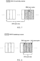
FIG. 6 , the DRX active time includes the PDCCH monitoring occasion. Assuming that the network device configures the PDCCH monitoring occasion to be the first three time domain symbols of a subframe, if a DRX timer expires in the second time domain symbol of the subframe, the terminal device needs to continue monitoring the PDCCH in the three time domain symbols. - As shown in
FIG. 7 , the DRX active time does not include the PDCCH monitoring occasion. Assuming that the network device configures the PDCCH monitoring occasion to be the first three time domain symbols of a subframe, if a DRX timer expires in the second time domain symbol of the subframe, the terminal device stops monitoring the PDCCH on a symbol preceding the three time domain symbols, that is, the terminal device does not monitor the PDCCH on the three time domain symbols. - As shown in
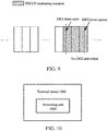
FIG. 8 , the DRX active time includes the PDCCH monitoring occasion. Assuming that the network device configures the PDCCH monitoring occasion to be the first three time domain symbols of a subframe, if a DRX timer starts in the first time domain symbol and expires in the third time domain symbol of the subframe, the terminal device monitors the PDCCH in the three time domain symbols. - As shown in
FIG. 9 , the DRX active time does not include the PDCCH monitoring occasion. Assuming that the network device configures the PDCCH monitoring occasion to be the first three time domain symbols of a subframe, if a DRX timer starts in the first time domain symbol and expires in the third time domain symbol of the subframe, then the terminal device may not have the DRX active time, that is, the terminal device does not monitor the PDCCH in the three time domain symbols. - Optionally, in
FIGs. 6 and8 , if the terminal device detects the PDCCH in the PDCCH monitoring occasion, the terminal device may restart a DRX onDuration Timer, and at this time, the time for monitoring the PDCCH by the terminal device may be prolonged. - Methods for discontinuous reception according to the embodiments of the present application have been described in detail above. Devices according to embodiments of the present application will be described below with reference to
FIGs. 10 to 12 . Technical features described in the method embodiments are applicable to the following device embodiments. -
FIG. 10 is a schematic block diagram of aterminal device 1000 according to an embodiment of the present application. As shown inFIG. 10 , theterminal device 1000 includes amonitoring unit 1010. Themonitoring unit 1010 is configured to monitor a physical downlink control channel (PDCCH) during a DRX active time. - Herein, if a DRX timer starts and/or expires in the PDCCH monitoring occasion, the DRX active time includes the PDCCH monitoring occasion, or the DRX active time does not include the PDCCH monitoring occasion.
- Therefore, when the DRX timer starts and/or expires in the PDCCH monitoring occasion, since the DRX active time of the terminal device includes the PDCCH monitoring occasion or the DRX active time does not include the PDCCH monitoring occasion, it can ensure that the terminal device monitors the downlink control channel more effectively.
- Optionally, the PDCCH monitoring occasion includes one or more consecutive time domain symbols.
- Optionally, the PDCCH monitoring occasion is configured by a network device.
- Optionally, the DRX timer is any one of the following timers: a DRX onDuration Timer, a DRX Inactivity Timer, a DRX Retransmission TimerUL, a DRX Retransmission TimerDL, and a Contention Resolution Timer.
- Optionally, that the DRX timer starts and/or expires in the PDCCH monitoring occasion includes that a starting or expiry time of the DRX timer is located in the PDCCH monitoring occasion except a starting time and an ending time of the PDCCH monitoring occasion.
- Optionally, that the DRX timer starts and/or expires in the PDCCH monitoring occasion includes that a starting time of the DRX timer is located after a starting time of the PDCCH monitoring occasion, and an expiry time of the DRX timer is located before an ending time of the PDCCH monitoring occasion.
- Optionally, the terminal device further includes a processing unit, the processing unit is configured to start or restart a DRX onDuration Timer if the PDCCH is detected by the
monitoring unit 1010 in the PDCCH monitoring occasion. - It should be understood that the
terminal device 1100 may perform corresponding operations performed by the terminal device in theabove method 300, which will not be described in detail herein for sake of brevity. -
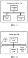
FIG. 11 is a schematic diagram of structure of aterminal device 1100 according to an embodiment of the present application. As shown inFIG. 11 , the terminal device includes aprocessor 1110, atransceiver 1120, and amemory 1130, wherein theprocessor 1110, thetransceiver 1120, and thememory 1130 communicate with each other through an internal connection path. Thememory 1130 is used for storing instructions, and theprocessor 1110 is used for executing instructions stored in thememory 1130 to control thetransceiver 1120 to send or receive signals. - Optionally, the
processor 1110 may call program codes stored in thememory 1130 to perform corresponding operations performed by the terminal device in themethod 300, which will not be described here repeatedly for sake of brevity. - It should be understood that the processor in the embodiment of the present application may be an integrated circuit chip with a capability for processing signals. In an implementation process, actions of the method embodiments described above may be accomplished by integrated logic circuits of hardware in the processor or instructions in the form of software. The above processor may be a general purpose processor, a digital signal processor (DSP), an application specific integrated circuit (ASIC), a field programmable gate array (FPGA), or other programmable logic device, discrete gate or transistor logic device, or discrete hardware component. The processor may implement or perform various methods, acts and logic block diagrams disclosed in embodiments of the present application. The general purpose processor may be a microprocessor, or the processor may be any conventional processor or the like. The acts of the methods disclosed in connection with the embodiments of the present application may be directly embodied by the execution of the hardware decoding processor, or by execution of a combination of hardware in a decoding processor and software modules. The software modules may be located in a storage medium commonly used in the art, such as a random access memory, flash memory, read-only memory, programmable read-only memory or electrically erasable programmable memory, or register. The storage medium is located in the memory, and the processor reads the information in the memory and completes the acts of the above method in combination with its hardware.
- It should be understood that the memory in embodiments of the present application may be a transitory memory or non-transitory memory, or may include both transitory and non-transitory memories. The non-transitory memory may be a read-only memory (ROM), programmable ROM (PROM), an erasable programmable ROM (EPROM), an electrically erasable programmable ROM (EEPROM), or a flash memory. The transitory memory may be a random access memory (RAM) which serves as an external cache. As an example, but not as a limitation, many forms of RAMs are available, such as a static random access memory (SRAM), a dynamic random access memory (DRAM), a synchronous dynamic random access memory (SDRAM), a double data rate SDRAM (DDR SDRAM), an enhanced SDRAM (ESDRAM), a Synchlink DRAM (SLDRAM), and a Direct Rambus RAM (DR RAM). It should be noted that the memories of the systems and methods of the present application described herein are intended to include, but not limited to, these and any other suitable types of memories.
-
FIG. 12 is a schematic diagram of structure of a system chip according to an embodiment of the present application. Thesystem chip 1200 ofFIG. 12 includes aninput interface 1201, anoutput interface 1202, at least oneprocessor 1203, and amemory 1204. Theinput interface 1201, theoutput interface 1202, theprocessor 1203, and thememory 1204 are connected to each other through an internal connection path. Theprocessor 1203 is used for executing codes in thememory 1204. - Optionally, when the codes are executed, the
processor 1203 may implement the operations implemented by the terminal device in themethod 300. For sake of brevity, it will not be repeated here. - Those of ordinary skill in the art will recognize that the exemplary elements and algorithm acts described in combination with the embodiments disclosed herein can be implemented in electronic hardware, or a combination of computer software and electronic hardware. Whether these functions are implemented in hardware or software depends on the specific application and design constraints of the technical solution. Skilled artisans may use different methods to implement the described functions in respect to each specific application, but such implementation should not be considered to be beyond the scope of the present application.
- Those skilled in the art may clearly understand that for convenience and conciseness of description, the specific working processes of the systems, apparatuses and units described above may refer to the corresponding processes in the method embodiments and will not be described repeatedly here.
- In several embodiments provided by the present application, it should be understood that the disclosed systems, apparatuses and methods may be implemented in other ways. For example, the apparatus embodiment described above is only illustrative, for example, the division of the unit is only a logical function division, and there may be other ways of division in actual implementations, for example, multiple units or components may be combined or integrated into another system, or some features may be ignored or not executed. On the other hand, the mutual coupling or direct coupling or communication connection shown or discussed may be indirect coupling or communication connection through some interfaces, apparatuses or units, and may be in electrical, mechanical or other forms.
- The unit described as a separate component may or may not be physically separated, and the component shown as a unit may or may not be a physical unit, i.e., it may be located in one place or may be distributed over multiple network units. Some or all of the units may be selected according to actual needs to achieve the purpose of the solution of the embodiments.
- In addition, various functional units in various embodiments of the present application may be integrated in one monitoring unit, or the various units may be physically present separately, or two or more units may be integrated in one unit.
- The functions may be stored in a computer readable storage medium if realized in a form of software functional units and sold or used as a separate product. Based on this understanding, the technical solution of the present application, in essence, or the part contributing to the prior art, or the part of the technical solution, may be embodied in the form of a software product stored in a storage medium, including a number of instructions for causing a computer device (which may be a personal computer, a server, or a network device and the like) to perform all or part of the acts of the method described in various embodiments of the present application. The aforementioned storage medium includes various media capable of storing program codes, such as a U disk, a mobile hard disk, a read-only memory (ROM), a random access memory (RAM), a magnetic disk, or an optical disk.
- What are described above are merely exemplary embodiments of the present application, but the protection scope of the present application is not limited thereto. Any variation or substitution that may be easily conceived by a person skilled in the art within the technical scope disclosed by the present application shall be included within the protection scope of the present application. Therefore, the protection scope of the present application shall be subjected to the protection scope of the claims.
Claims (14)
- A method for discontinuous reception (DRX), comprising:monitoring, by a terminal device, a physical downlink control channel (PDCCH) during a DRX active time;wherein, if a DRX timer starts and/or expires in a PDCCH monitoring occasion, the DRX active time comprises the PDCCH monitoring occasion, or the DRX active time does not comprises the PDCCH monitoring occasion.
- The method of claim 1, wherein the PDCCH monitoring occasion comprises one or more consecutive time domain symbols.
- The method of claim 1 or 2, wherein the PDCCH monitoring occasion is configured by a network device.
- The method of any one of claims 1 to 3, wherein the DRX timer is any one of the following timers:
a DRX onDuration Timer, a DRX Inactivity Timer, a DRX Retransmission TimerUL, a DRX Retransmission TimerDL, and a Contention Resolution Timer. - The method of any one of claims 1 to 4, wherein that the DRX timer starts and/or expires in the PDCCH monitoring occasion comprises:
a starting or expiry time of the DRX timer is located in the PDCCH monitoring occasion except a starting time and an ending time of the PDCCH monitoring occasion. - The method of any one of claims 1 to 4, wherein that the DRX timer starts and/or expires in the PDCCH monitoring occasion comprises:
a starting time of the DRX timer is located after a starting time of the PDCCH monitoring occasion, and an expiry time of the DRX timer is located before an ending time of the PDCCH monitoring occasion. - The method of any one of claims 1 to 6, the method further comprising:
if the terminal device detects the PDCCH in the PDCCH monitoring occasion, starting or restarting, by the terminal device, a DRX onDuration Timer. - A terminal device, comprising:a monitoring unit, configured to monitor a physical downlink control channel (PDCCH) in a discontinuous reception (DRX) active time;wherein, if a DRX timer starts and/or expires in a PDCCH monitoring occasion, the DRX active time comprises the PDCCH monitoring occasion, or the DRX active time does not comprises the PDCCH monitoring occasion.
- The terminal device of claim 8, wherein the PDCCH monitoring occasion comprises one or more consecutive time domain symbols.
- The terminal device of claim 8 or 9, wherein the PDCCH monitoring occasion is configured by a network device.
- The terminal device of any one of claims 8 to 10, wherein the DRX timer is any one of the following timers:
a DRX onDuration Timer, a DRX Inactivity Timer, a DRX Retransmission TimerUL, a DRX Retransmission TimerDL, and a Contention Resolution Timer. - The terminal device of any one of claims 8 to 11, wherein that the DRX timer starts and/or expires in the PDCCH monitoring occasion comprises:
a starting or expiry time of the DRX timer is located in the PDCCH monitoring occasion except a starting time and an ending time of the PDCCH monitoring occasion. - The terminal device of any one of claims 8 to 12, wherein that the DRX timer starts and/or expires in the PDCCH monitoring occasion comprises:
a starting time of the DRX timer is located after a starting time of the PDCCH monitoring occasion, and an expiry time of the DRX timer is located before an ending time of the PDCCH monitoring occasion. - The terminal device of any one of claims 8 to 13, further comprising a processing unit; wherein the processing unit is configured to, if the PDCCH is detected by the monitoring unit in the PDCCH monitoring occasion, start or restart a DRX onDuration Timer.
Applications Claiming Priority (1)
| Application Number | Priority Date | Filing Date | Title |
|---|---|---|---|
| PCT/CN2018/074844 WO2019148403A1 (en) | 2018-01-31 | 2018-01-31 | Method and device for discontinuous transmission |
Publications (3)
| Publication Number | Publication Date |
|---|---|
| EP3735046A1 true EP3735046A1 (en) | 2020-11-04 |
| EP3735046A4 EP3735046A4 (en) | 2021-01-20 |
| EP3735046B1 EP3735046B1 (en) | 2025-01-01 |
Family
ID=67479953
Family Applications (1)
| Application Number | Title | Priority Date | Filing Date |
|---|---|---|---|
| EP18903421.8A Active EP3735046B1 (en) | 2018-01-31 | 2018-01-31 | Method and device for discontinuous transmission |
Country Status (9)
| Country | Link |
|---|---|
| US (1) | US11641691B2 (en) |
| EP (1) | EP3735046B1 (en) |
| JP (1) | JP7027561B2 (en) |
| KR (1) | KR102339953B1 (en) |
| CN (2) | CN111264077A (en) |
| AU (1) | AU2018405905B2 (en) |
| MX (1) | MX2020007963A (en) |
| SG (1) | SG11202007186SA (en) |
| WO (1) | WO2019148403A1 (en) |
Families Citing this family (3)
| Publication number | Priority date | Publication date | Assignee | Title |
|---|---|---|---|---|
| CN114270945B (en) * | 2019-08-16 | 2024-10-18 | 华为技术有限公司 | A communication method and device |
| EP4102887B1 (en) | 2021-06-10 | 2025-10-15 | Samsung Electronics Co., Ltd. | Communication device supporting discontinuous reception operation and operating method thereof |
| CN115988648B (en) * | 2022-12-16 | 2026-01-09 | 展讯通信(上海)有限公司 | Downlink control information monitoring method and communication device |
Family Cites Families (14)
| Publication number | Priority date | Publication date | Assignee | Title |
|---|---|---|---|---|
| US8488521B2 (en) * | 2008-03-14 | 2013-07-16 | Interdigital Patent Holdings, Inc. | Behavior for wireless transmit/receive unit and MAC control elements for LTE DRX operations |
| PT3419208T (en) * | 2009-06-15 | 2021-04-13 | Guangdong Oppo Mobile Telecommunications Corp Ltd | Method for discontinuous reception operation for long term evolution advanced carrier aggregation |
| KR101664279B1 (en) * | 2010-02-16 | 2016-10-12 | 삼성전자주식회사 | Controlling method and apparatus for discontinuous reception in a wireless communication system |
| CN102421148B (en) * | 2010-09-28 | 2016-03-30 | 华为技术有限公司 | A kind of method and subscriber equipment controlling plurality of communication systems realization communication |
| CN102548013B (en) * | 2010-12-24 | 2015-05-13 | 中兴通讯股份有限公司 | Time division multiplexing communication method and system adopted during co-existing of multiple radio techniques in terminal |
| CN102256321A (en) | 2011-07-14 | 2011-11-23 | 新邮通信设备有限公司 | Method and system for controlling terminal cell handover under discontinuous reception (DRX) |
| US8781502B1 (en) * | 2013-02-01 | 2014-07-15 | Swirl Networks, Inc. | Systems and methods for display of supplemental content responsive to location |
| CN106034318B (en) * | 2015-03-16 | 2019-10-29 | 中国移动通信集团公司 | A kind of control method and device of discontinuous reception |
| JP6813481B2 (en) | 2015-05-15 | 2021-01-13 | 京セラ株式会社 | Wireless terminals and base stations |
| US10834763B2 (en) * | 2015-11-04 | 2020-11-10 | Lg Electronics Inc. | Method and apparatus for handling overlap of different channels in wireless communication system |
| CN106899941B (en) * | 2015-12-18 | 2020-08-07 | 普天信息技术有限公司 | Method and device for discontinuously monitoring control channel in trunking communication system |
| WO2017204524A1 (en) * | 2016-05-23 | 2017-11-30 | 엘지전자 주식회사 | Method and user equipment for receiving downlink control information |
| CN107257564B (en) * | 2017-07-18 | 2020-08-28 | 京信通信系统(中国)有限公司 | Terminal scheduling method and network equipment |
| EP3665849B1 (en) * | 2017-08-10 | 2024-05-01 | InterDigital Patent Holdings, Inc. | Enhanced connected mode drx procedures for nr |
-
2018
- 2018-01-31 CN CN201880067689.6A patent/CN111264077A/en active Pending
- 2018-01-31 WO PCT/CN2018/074844 patent/WO2019148403A1/en not_active Ceased
- 2018-01-31 MX MX2020007963A patent/MX2020007963A/en unknown
- 2018-01-31 SG SG11202007186SA patent/SG11202007186SA/en unknown
- 2018-01-31 JP JP2020540774A patent/JP7027561B2/en active Active
- 2018-01-31 AU AU2018405905A patent/AU2018405905B2/en active Active
- 2018-01-31 KR KR1020207023792A patent/KR102339953B1/en active Active
- 2018-01-31 EP EP18903421.8A patent/EP3735046B1/en active Active
- 2018-01-31 CN CN202010595493.3A patent/CN111757442A/en active Pending
-
2020
- 2020-07-15 US US16/929,277 patent/US11641691B2/en active Active
Also Published As
| Publication number | Publication date |
|---|---|
| KR20200110692A (en) | 2020-09-24 |
| JP2021511749A (en) | 2021-05-06 |
| WO2019148403A1 (en) | 2019-08-08 |
| CN111264077A (en) | 2020-06-09 |
| MX2020007963A (en) | 2020-09-24 |
| US20200344840A1 (en) | 2020-10-29 |
| US11641691B2 (en) | 2023-05-02 |
| EP3735046B1 (en) | 2025-01-01 |
| AU2018405905B2 (en) | 2021-07-29 |
| JP7027561B2 (en) | 2022-03-01 |
| SG11202007186SA (en) | 2020-08-28 |
| AU2018405905A1 (en) | 2020-08-20 |
| CN111757442A (en) | 2020-10-09 |
| KR102339953B1 (en) | 2021-12-16 |
| EP3735046A4 (en) | 2021-01-20 |
Similar Documents
| Publication | Publication Date | Title |
|---|---|---|
| CN114271021B (en) | Method and device for determining starting status of discontinuous reception duration timer | |
| US12075354B2 (en) | Wireless communication method and device | |
| EP3627905B1 (en) | Communication method, terminal device and network device | |
| EP4637223A2 (en) | Discontinuous reception method, terminal device and network device | |
| EP3745791B1 (en) | Method and device for discontinuous reception | |
| US20210014786A1 (en) | Signal transmission method and device | |
| CN113678513A (en) | Method and apparatus for discontinuous reception | |
| US11641691B2 (en) | Method and device for discontinuous transmission | |
| CN116437428A (en) | Method and apparatus for signal transmission |
Legal Events
| Date | Code | Title | Description |
|---|---|---|---|
| STAA | Information on the status of an ep patent application or granted ep patent |
Free format text: STATUS: THE INTERNATIONAL PUBLICATION HAS BEEN MADE |
|
| PUAI | Public reference made under article 153(3) epc to a published international application that has entered the european phase |
Free format text: ORIGINAL CODE: 0009012 |
|
| STAA | Information on the status of an ep patent application or granted ep patent |
Free format text: STATUS: REQUEST FOR EXAMINATION WAS MADE |
|
| 17P | Request for examination filed |
Effective date: 20200730 |
|
| AK | Designated contracting states |
Kind code of ref document: A1 Designated state(s): AL AT BE BG CH CY CZ DE DK EE ES FI FR GB GR HR HU IE IS IT LI LT LU LV MC MK MT NL NO PL PT RO RS SE SI SK SM TR |
|
| AX | Request for extension of the european patent |
Extension state: BA ME |
|
| A4 | Supplementary search report drawn up and despatched |
Effective date: 20201221 |
|
| RIC1 | Information provided on ipc code assigned before grant |
Ipc: H04W 52/02 20090101AFI20201215BHEP Ipc: H04W 68/02 20090101ALI20201215BHEP |
|
| DAV | Request for validation of the european patent (deleted) | ||
| DAX | Request for extension of the european patent (deleted) | ||
| STAA | Information on the status of an ep patent application or granted ep patent |
Free format text: STATUS: EXAMINATION IS IN PROGRESS |
|
| 17Q | First examination report despatched |
Effective date: 20211020 |
|
| GRAP | Despatch of communication of intention to grant a patent |
Free format text: ORIGINAL CODE: EPIDOSNIGR1 |
|
| STAA | Information on the status of an ep patent application or granted ep patent |
Free format text: STATUS: GRANT OF PATENT IS INTENDED |
|
| INTG | Intention to grant announced |
Effective date: 20240926 |
|
| GRAS | Grant fee paid |
Free format text: ORIGINAL CODE: EPIDOSNIGR3 |
|
| GRAA | (expected) grant |
Free format text: ORIGINAL CODE: 0009210 |
|
| STAA | Information on the status of an ep patent application or granted ep patent |
Free format text: STATUS: THE PATENT HAS BEEN GRANTED |
|
| AK | Designated contracting states |
Kind code of ref document: B1 Designated state(s): AL AT BE BG CH CY CZ DE DK EE ES FI FR GB GR HR HU IE IS IT LI LT LU LV MC MK MT NL NO PL PT RO RS SE SI SK SM TR |
|
| REG | Reference to a national code |
Ref country code: GB Ref legal event code: FG4D |
|
| REG | Reference to a national code |
Ref country code: DE Ref legal event code: R096 Ref document number: 602018078255 Country of ref document: DE |
|
| REG | Reference to a national code |
Ref country code: CH Ref legal event code: EP |
|
| REG | Reference to a national code |
Ref country code: IE Ref legal event code: FG4D |
|
| P01 | Opt-out of the competence of the unified patent court (upc) registered |
Free format text: CASE NUMBER: APP_9852/2025 Effective date: 20250226 |
|
| REG | Reference to a national code |
Ref country code: LT Ref legal event code: MG9D |
|
| REG | Reference to a national code |
Ref country code: NL Ref legal event code: MP Effective date: 20250101 |
|
| REG | Reference to a national code |
Ref country code: AT Ref legal event code: MK05 Ref document number: 1757591 Country of ref document: AT Kind code of ref document: T Effective date: 20250101 |
|
| PG25 | Lapsed in a contracting state [announced via postgrant information from national office to epo] |
Ref country code: NL Free format text: LAPSE BECAUSE OF FAILURE TO SUBMIT A TRANSLATION OF THE DESCRIPTION OR TO PAY THE FEE WITHIN THE PRESCRIBED TIME-LIMIT Effective date: 20250101 |
|
| PG25 | Lapsed in a contracting state [announced via postgrant information from national office to epo] |
Ref country code: FI Free format text: LAPSE BECAUSE OF FAILURE TO SUBMIT A TRANSLATION OF THE DESCRIPTION OR TO PAY THE FEE WITHIN THE PRESCRIBED TIME-LIMIT Effective date: 20250101 |
|
| PG25 | Lapsed in a contracting state [announced via postgrant information from national office to epo] |
Ref country code: PL Free format text: LAPSE BECAUSE OF FAILURE TO SUBMIT A TRANSLATION OF THE DESCRIPTION OR TO PAY THE FEE WITHIN THE PRESCRIBED TIME-LIMIT Effective date: 20250101 |
|
| PG25 | Lapsed in a contracting state [announced via postgrant information from national office to epo] |
Ref country code: ES Free format text: LAPSE BECAUSE OF FAILURE TO SUBMIT A TRANSLATION OF THE DESCRIPTION OR TO PAY THE FEE WITHIN THE PRESCRIBED TIME-LIMIT Effective date: 20250101 |
|
| PG25 | Lapsed in a contracting state [announced via postgrant information from national office to epo] |
Ref country code: NO Free format text: LAPSE BECAUSE OF FAILURE TO SUBMIT A TRANSLATION OF THE DESCRIPTION OR TO PAY THE FEE WITHIN THE PRESCRIBED TIME-LIMIT Effective date: 20250401 Ref country code: IS Free format text: LAPSE BECAUSE OF FAILURE TO SUBMIT A TRANSLATION OF THE DESCRIPTION OR TO PAY THE FEE WITHIN THE PRESCRIBED TIME-LIMIT Effective date: 20250501 |
|
| PG25 | Lapsed in a contracting state [announced via postgrant information from national office to epo] |
Ref country code: HR Free format text: LAPSE BECAUSE OF FAILURE TO SUBMIT A TRANSLATION OF THE DESCRIPTION OR TO PAY THE FEE WITHIN THE PRESCRIBED TIME-LIMIT Effective date: 20250101 |
|
| PG25 | Lapsed in a contracting state [announced via postgrant information from national office to epo] |
Ref country code: PT Free format text: LAPSE BECAUSE OF FAILURE TO SUBMIT A TRANSLATION OF THE DESCRIPTION OR TO PAY THE FEE WITHIN THE PRESCRIBED TIME-LIMIT Effective date: 20250502 Ref country code: LV Free format text: LAPSE BECAUSE OF FAILURE TO SUBMIT A TRANSLATION OF THE DESCRIPTION OR TO PAY THE FEE WITHIN THE PRESCRIBED TIME-LIMIT Effective date: 20250101 |
|
| PG25 | Lapsed in a contracting state [announced via postgrant information from national office to epo] |
Ref country code: GR Free format text: LAPSE BECAUSE OF FAILURE TO SUBMIT A TRANSLATION OF THE DESCRIPTION OR TO PAY THE FEE WITHIN THE PRESCRIBED TIME-LIMIT Effective date: 20250402 Ref country code: BG Free format text: LAPSE BECAUSE OF FAILURE TO SUBMIT A TRANSLATION OF THE DESCRIPTION OR TO PAY THE FEE WITHIN THE PRESCRIBED TIME-LIMIT Effective date: 20250101 |
|
| PG25 | Lapsed in a contracting state [announced via postgrant information from national office to epo] |
Ref country code: AT Free format text: LAPSE BECAUSE OF FAILURE TO SUBMIT A TRANSLATION OF THE DESCRIPTION OR TO PAY THE FEE WITHIN THE PRESCRIBED TIME-LIMIT Effective date: 20250101 |
|
| PG25 | Lapsed in a contracting state [announced via postgrant information from national office to epo] |
Ref country code: CZ Free format text: LAPSE BECAUSE OF FAILURE TO SUBMIT A TRANSLATION OF THE DESCRIPTION OR TO PAY THE FEE WITHIN THE PRESCRIBED TIME-LIMIT Effective date: 20250101 |
|
| REG | Reference to a national code |
Ref country code: CH Ref legal event code: PL |
|
| PG25 | Lapsed in a contracting state [announced via postgrant information from national office to epo] |
Ref country code: SE Free format text: LAPSE BECAUSE OF FAILURE TO SUBMIT A TRANSLATION OF THE DESCRIPTION OR TO PAY THE FEE WITHIN THE PRESCRIBED TIME-LIMIT Effective date: 20250101 |
|
| PG25 | Lapsed in a contracting state [announced via postgrant information from national office to epo] |
Ref country code: LU Free format text: LAPSE BECAUSE OF NON-PAYMENT OF DUE FEES Effective date: 20250131 |
|
| REG | Reference to a national code |
Ref country code: DE Ref legal event code: R097 Ref document number: 602018078255 Country of ref document: DE |
|
| PG25 | Lapsed in a contracting state [announced via postgrant information from national office to epo] |
Ref country code: SM Free format text: LAPSE BECAUSE OF FAILURE TO SUBMIT A TRANSLATION OF THE DESCRIPTION OR TO PAY THE FEE WITHIN THE PRESCRIBED TIME-LIMIT Effective date: 20250101 |
|
| PG25 | Lapsed in a contracting state [announced via postgrant information from national office to epo] |
Ref country code: DK Free format text: LAPSE BECAUSE OF FAILURE TO SUBMIT A TRANSLATION OF THE DESCRIPTION OR TO PAY THE FEE WITHIN THE PRESCRIBED TIME-LIMIT Effective date: 20250101 |
|
| PG25 | Lapsed in a contracting state [announced via postgrant information from national office to epo] |
Ref country code: MC Free format text: LAPSE BECAUSE OF FAILURE TO SUBMIT A TRANSLATION OF THE DESCRIPTION OR TO PAY THE FEE WITHIN THE PRESCRIBED TIME-LIMIT Effective date: 20250101 |
|
| PG25 | Lapsed in a contracting state [announced via postgrant information from national office to epo] |
Ref country code: IT Free format text: LAPSE BECAUSE OF FAILURE TO SUBMIT A TRANSLATION OF THE DESCRIPTION OR TO PAY THE FEE WITHIN THE PRESCRIBED TIME-LIMIT Effective date: 20250101 |
|
| PG25 | Lapsed in a contracting state [announced via postgrant information from national office to epo] |
Ref country code: BE Free format text: LAPSE BECAUSE OF NON-PAYMENT OF DUE FEES Effective date: 20250131 |
|
| PG25 | Lapsed in a contracting state [announced via postgrant information from national office to epo] |
Ref country code: CH Free format text: LAPSE BECAUSE OF NON-PAYMENT OF DUE FEES Effective date: 20250131 |
|
| PG25 | Lapsed in a contracting state [announced via postgrant information from national office to epo] |
Ref country code: EE Free format text: LAPSE BECAUSE OF FAILURE TO SUBMIT A TRANSLATION OF THE DESCRIPTION OR TO PAY THE FEE WITHIN THE PRESCRIBED TIME-LIMIT Effective date: 20250101 |
|
| REG | Reference to a national code |
Ref country code: BE Ref legal event code: MM Effective date: 20250131 |
|
| PG25 | Lapsed in a contracting state [announced via postgrant information from national office to epo] |
Ref country code: RO Free format text: LAPSE BECAUSE OF FAILURE TO SUBMIT A TRANSLATION OF THE DESCRIPTION OR TO PAY THE FEE WITHIN THE PRESCRIBED TIME-LIMIT Effective date: 20250101 |
|
| PG25 | Lapsed in a contracting state [announced via postgrant information from national office to epo] |
Ref country code: SK Free format text: LAPSE BECAUSE OF FAILURE TO SUBMIT A TRANSLATION OF THE DESCRIPTION OR TO PAY THE FEE WITHIN THE PRESCRIBED TIME-LIMIT Effective date: 20250101 |
|
| PLBE | No opposition filed within time limit |
Free format text: ORIGINAL CODE: 0009261 |
|
| STAA | Information on the status of an ep patent application or granted ep patent |
Free format text: STATUS: NO OPPOSITION FILED WITHIN TIME LIMIT |
|
| 26N | No opposition filed |
Effective date: 20251002 |
|
| PGFP | Annual fee paid to national office [announced via postgrant information from national office to epo] |
Ref country code: GB Payment date: 20251211 Year of fee payment: 9 |
|
| PG25 | Lapsed in a contracting state [announced via postgrant information from national office to epo] |
Ref country code: FR Free format text: LAPSE BECAUSE OF NON-PAYMENT OF DUE FEES Effective date: 20250301 |
|
| PG25 | Lapsed in a contracting state [announced via postgrant information from national office to epo] |
Ref country code: IE Free format text: LAPSE BECAUSE OF NON-PAYMENT OF DUE FEES Effective date: 20250131 |
|
| PGFP | Annual fee paid to national office [announced via postgrant information from national office to epo] |
Ref country code: DE Payment date: 20251210 Year of fee payment: 9 |