EP3734815A1 - Cylindrical linear motor - Google Patents
Cylindrical linear motor Download PDFInfo
- Publication number
- EP3734815A1 EP3734815A1 EP18896487.8A EP18896487A EP3734815A1 EP 3734815 A1 EP3734815 A1 EP 3734815A1 EP 18896487 A EP18896487 A EP 18896487A EP 3734815 A1 EP3734815 A1 EP 3734815A1
- Authority
- EP
- European Patent Office
- Prior art keywords
- magnetic pole
- permanent magnet
- axial length
- main magnetic
- linear motor
- Prior art date
- Legal status (The legal status is an assumption and is not a legal conclusion. Google has not performed a legal analysis and makes no representation as to the accuracy of the status listed.)
- Withdrawn
Links
Images


Classifications
-
- H—ELECTRICITY
- H02—GENERATION; CONVERSION OR DISTRIBUTION OF ELECTRIC POWER
- H02K—DYNAMO-ELECTRIC MACHINES
- H02K41/00—Propulsion systems in which a rigid body is moved along a path due to dynamo-electric interaction between the body and a magnetic field travelling along the path
- H02K41/02—Linear motors; Sectional motors
- H02K41/03—Synchronous motors; Motors moving step by step; Reluctance motors
-
- H—ELECTRICITY
- H02—GENERATION; CONVERSION OR DISTRIBUTION OF ELECTRIC POWER
- H02K—DYNAMO-ELECTRIC MACHINES
- H02K41/00—Propulsion systems in which a rigid body is moved along a path due to dynamo-electric interaction between the body and a magnetic field travelling along the path
- H02K41/02—Linear motors; Sectional motors
- H02K41/03—Synchronous motors; Motors moving step by step; Reluctance motors
- H02K41/031—Synchronous motors; Motors moving step by step; Reluctance motors of the permanent magnet type
-
- H—ELECTRICITY
- H02—GENERATION; CONVERSION OR DISTRIBUTION OF ELECTRIC POWER
- H02K—DYNAMO-ELECTRIC MACHINES
- H02K1/00—Details of the magnetic circuit
- H02K1/06—Details of the magnetic circuit characterised by the shape, form or construction
- H02K1/12—Stationary parts of the magnetic circuit
- H02K1/17—Stator cores with permanent magnets
-
- H—ELECTRICITY
- H02—GENERATION; CONVERSION OR DISTRIBUTION OF ELECTRIC POWER
- H02K—DYNAMO-ELECTRIC MACHINES
- H02K1/00—Details of the magnetic circuit
- H02K1/06—Details of the magnetic circuit characterised by the shape, form or construction
- H02K1/22—Rotating parts of the magnetic circuit
- H02K1/27—Rotor cores with permanent magnets
Definitions
- the present invention relates to a cylindrical linear motor.
- Some cylindrical linear motors include, for example, an armature having a cylindrical core having a plurality of teeth arranged side by side in the axial direction on the outer periphery and U-phase, V-phase, and W-phase windings mounted in slots between teeth; and a stator consisting of a cylindrical yoke provided on the outer periphery of the armature and a plurality of permanent magnets attached to the inner periphery of the base so that the S poles and the N poles are alternately arranged in the axial direction.
- the permanent magnets in the stator are arranged in a Halbach array in which the permanent magnets of the main magnetic pole magnetized in the radial direction and the permanent magnets of the sub magnetic pole magnetized in the axial direction are arranged alternately in order to improve the thrust.
- the residual magnetic flux density of the permanent magnet of the main magnetic pole is increased to improve the thrust, but since a large magnetic field acts on the permanent magnet of the sub magnetic pole in the permanent magnet of the main magnetic pole and the permanent magnet of the sub magnetic pole, the coercive force of the permanent magnet of the sub magnetic pole is made higher than that of the permanent magnet of the main magnetic pole to prevent demagnetization.
- the permanent magnets of the main magnetic pole and the sub magnetic pole have the same axial length, the magnetic resistance between the permanent magnet of the main magnetic pole and the armature is large, and even if the residual magnetic flux density of the permanent magnet of the main magnetic pole is increased, it is difficult to further improve the thrust of the cylindrical linear motor.
- an object of the present invention is to provide a cylindrical linear motor capable of effectively improving the thrust.
- a cylindrical linear motor includes a core having a cylindrical yoke, and a plurality of teeth that are annular and are provided at intervals in an axial direction on an outer periphery of the yoke; a winding mounted in slots between the teeth; and a field which is cylindrical and in which the core is inwardly inserted movably in the axial direction to arrange N poles and S poles alternately in the axial direction, wherein the field has permanent magnets of a main magnetic pole radially magnetized and permanent magnets of a sub magnetic pole axially magnetized that are alternately arranged in a Halbach array in the axial direction, an axial length of the permanent magnet of the main magnetic pole is longer than an axial length of the permanent magnet of the sub magnetic pole, the permanent magnet of the sub magnetic pole has a coercive force higher than that of the permanent magnet of the main magnetic pole.
- the axial length of the permanent magnet of the main magnetic pole can be increased to reduce the magnetic resistance between the permanent magnet of the main magnetic pole and the core, and to increase the magnetic field acting on the core.
- the permanent magnet of the sub magnetic pole has a coercive force higher than that of the permanent magnet of the main magnetic pole, a permanent magnet with a high residual magnetic flux density can be used for the permanent magnet of the main magnetic pole while suppressing the demagnetization of the permanent magnet of the sub magnetic pole to which a large magnetic field is applied.
- a cylindrical linear motor 1 includes a core 2 having a cylindrical yoke 3 and a plurality of annular teeth 4 provided on the outer periphery of the yoke 3; a winding 5 mounted between the teeth 4, 4; and a field 7which is cylindrical and into which the core 2 is inwardly inserted movably in the axial direction.
- the core 2 is configured to include a cylindrical yoke 3; and a plurality of teeth 4 which are annular and are provided on the outer periphery of the yoke 3 at intervals in the axial direction, and serve as a movable element.
- the yoke 3 has a cylindrical shape as described above, and the thickness thereof is secured so that the sectional area thereof is equal to or larger than an area of the cross section obtained by cutting the teeth 4 with said cylinder wherever from the inner periphery to the outer periphery of the teeth 4 with the cylinder around the axis A of the core 2 (see Fig. 2 ).
- each tooth 4 is annular and, except for the teeth 4 arranged at both ends of the core 2, has an equal-leg trapezoidal shape in which the width Wo of the outer peripheral end 4a is smaller than the width Wi of the inner peripheral end 4b in the axial direction so that the side surfaces 4c and 4d on both sides in the axial direction are tapered surfaces inclined at an equal angle with respect to the outer peripheral end 4a.
- an inner angle ⁇ formed by a side surface 4c, 4d and an orthogonal plane O orthogonal to the axis of the core 2 in a cross section cut along a plane including the axis A of the core 2 is set to an angle in the range of 6 degrees to 12 degrees.
- the end teeth 4 have a cross-sectional shape in which a tooth 4 other than the end teeth 4 is cut in half on a plane orthogonal to the axis of the core 2.
- the cross-sectional shape of each tooth 4 is a trapezoidal shape in which the width of the outer peripheral end is smaller than the width of the inner peripheral end.
- a total of nine slots 6 consisting of spaces are provided between the adjacent teeth 4, 4 in Fig. 1 . Additionally, this slot 6 is mounted with the winding 5 wound therearound.
- the winding 5 is a three-phase winding of U phase, V phase and W phase.
- the nine slots 6 are mounted with W phase and U phase, U phase, U phase, U phase and V phase, V phase, V phase, V phase and W phase, W phase and W phase windings 5 in order from the left side in Fig. 1 .
- the core 2 configured in this way is mounted on an outer periphery of a rod 11 formed of a nonmagnetic material, which is an output shaft. Specifically, the core 2 is fixed to the rod 11 by annular stoppers 12, 13 having the right end and left end thereof fixed to the rod 11 in Fig. 1 .
- the field 7 is, in the present embodiment, configured to include an outer tube 8 formed of a cylindrical non-magnetic material; an inner tube 9 formed of a cylindrical non-magnetic material inserted into the outer tube 8; and permanent magnets 10a of an annular main magnetic pole and permanent magnets 10b of an annular sub magnetic pole, which are alternately stacked and inserted in the axial direction over the entire annular gap between the outer tube 8 and the inner tube 9.
- each permanent magnet 10a, 10b is arranged on the inner peripheral side of the field 7 in such a direction that a region from the center to the center of the permanent magnets 10b of the sub magnetic pole on both sides sandwiching the permanent magnet 10a of the main magnetic pole serves as one magnetic pole.
- the permanent magnets 10a of the main magnetic pole and the permanent magnets 10b of the sub magnetic pole are arranged in a Halbach array, and the S poles and the N poles are arranged so as to appear alternately in the axial direction on the inner peripheral side of the field 7.
- the axial length L1 of the permanent magnet 10a of the main magnetic pole is longer than the axial length L2 of the permanent magnet 10b of the sub magnetic pole, and in the present embodiment, the axial length L1 of the permanent magnet 10a of the main magnetic pole and the axial length L2 of the permanent magnet 10b of the sub magnetic pole are set so as to satisfy 0.2 ⁇ L2 / L1 ⁇ 0.4. Since the magnetic resistance between the core 2 and the permanent magnet 10a of the main magnetic pole can be reduced and the magnetic field acting on the core 2 can be increased by increasing the axial length of the permanent magnet 10a of the main magnetic pole, the thrust of the cylindrical linear motor 1 can be improved.
- the permanent magnet 10b of the sub magnetic pole has a coercive force higher than that of the permanent magnet 10a of the main magnetic pole.
- the residual magnetic flux density and the coercive force of a permanent magnet are closely related to each other, and they are generally in such a conflicting relationship with each other that increasing the residual magnetic flux density decreases the coercive force, and increasing the coercive force decreases the residual magnetic flux density. Since a large magnetic field is applied in the direction of demagnetization to the permanent magnet 10b of the sub magnetic pole in the Halbach array, the coercive force of the permanent magnet 10b of the sub magnetic pole is increased to suppress demagnetization so that a large magnetic field can act on the core 2.
- the strength of the magnetic field acting on the core 2 depends on the number of lines of magnetic force of the permanent magnets 10a of the main magnetic pole. Therefore, a permanent magnet having a high residual magnetic flux density as the permanent magnet 10a of the main magnetic pole is used so that a large magnetic field can act on the core 2.
- the material of the permanent magnet 10b of the sub magnetic pole is a material having a coercive force higher than that of the material of the permanent magnet 10a of the main magnetic pole.
- the combination of the permanent magnet 10a of the main magnetic pole and the permanent magnet 10b of the sub magnetic pole can be easily realized by selecting the materials.
- the permanent magnet 10a of the main magnetic pole is made of a material having a high residual magnetic flux density containing neodymium, iron, and boron as main components
- the permanent magnet 10b of the sub magnetic pole is made of a magnet that is hard to demagnetize obtained by adding dysprosium to the material described above.
- the core 2 is inserted on the inner peripheral side of the field 7, and the field 7 causes a magnetic field to act on the core 2.
- the field 7 is only needed to cause a magnetic field to act on the movable range of the core 2, it is only needed to determine the installation range of the permanent magnets 10 according to the movable range of the core 2. Therefore, the permanent magnets 10a, 10b may not be provided in a range that cannot face the core 2 in the annular gap between the outer tube 8 and the inner tube 9.
- the left end of the outer tube 8 and the inner tube 9 in Fig. 1 is closed by a cap 14, and the right end of the outer tube 8 and the inner tube 9 in Fig. 1 is closed by an annular rod guide 15 for guiding the axial movement of the rod 11 inserted in the inner periphery.
- stoppers 12, 13 are in sliding contact with the inner periphery of the inner tube 9, and the stoppers 12, 13 allow the core 2 to move smoothly in the axial direction together with the rod 11 without axial displacement with respect to the field 7.
- the inner tube 9 plays a role to form a gap between the outer periphery of the core 2 and the inner periphery of each of the permanent magnets 10a, 10b, and also guide the axial movement of the core 2 in cooperation with the stoppers 12, 13.
- the cap 14 is provided with a connector 14a for connecting the cable C connected to the windings 5 to an external power supply (not shown), so that the windings 5 can be energized from an external power supply.
- the axial length of the outer tube 8 and the inner tube 9 is longer than the axial length of the core 2, and the core 2 can stroke in the left and right directions in Fig. 1 in a range of the axial length of the field 7.
- the thrust of the cylindrical linear motor 1 and the moving direction of the core 2 can be controlled.
- the control method described above is an example, and it is not limited thereto.
- the core 2 is an armature and a movable element, and the field 7 acts as a stator.
- the thrust for suppressing the relative displacement can be generated by energizing the winding 5 or an induced electromotive force generated in the winding 5 to cause the cylindrical linear motor 1 to dampen the vibration and motion of the device due to the external force, and the energy regeneration that generates electric power from the external force is also possible.
- the cylindrical linear motor 1 of the present invention includes a cylindrical linear motor includes: a core 2 having a cylindrical yoke 3, and a plurality of teeth 4 that are annular and are provided at intervals in an axial direction on an outer periphery of the yoke 3; a winding 5 mounted in slots 6 between the teeth 4, 4; and a field 7 which is cylindrical and in which the core 2 is inwardly inserted movably in the axial direction to arrange N poles and S poles alternately in the axial direction, wherein the field 7 has permanent magnets 10a of a main magnetic pole radially magnetized and permanent magnets 10b of a sub magnetic pole axially magnetized that are alternately arranged in a Halbach array in the axial direction, an axial length L1 of the permanent magnet 10a of the main magnetic pole is longer than an axial length L2 of the permanent magnet 10b of the sub magnetic pole, and the permanent magnet 10b of the sub magnetic pole has a coercive force higher than that of the permanent magnet 10a
- the cylindrical linear motor 1 When the cylindrical linear motor 1 is configured in this way, the axial length of the permanent magnet 10a of the main magnetic pole can be increased, and the magnetic resistance between the permanent magnet 10a of the main magnetic pole and the core 2 can be reduced. Thus, the magnetic field acting on the core 2 can be increased. Also, since the permanent magnet 10b of the sub magnetic pole has a higher coercive force than the permanent magnet 10a of the main magnetic pole, while suppressing the demagnetization of the permanent magnet 10b of the sub magnetic pole to which a large magnetic field is applied, a permanent magnet having a high residual magnetic flux density can be used as the permanent magnet 10a.
- the magnetic resistance between the permanent magnet 10a of the main magnetic pole and the core 2 can be reduced while suppressing the demagnetization of the permanent magnet 10b of the sub magnetic pole, and the thrust can be effectively improved.
- Fig. 3 shows the relationship between the value obtained by dividing the axial length L2 of the permanent magnet 10b of the sub magnetic pole by the axial length L1 of the permanent magnet 10a of the main magnetic pole and the thrust of the cylindrical linear actuator 1.
- the thrust can be further improved while avoiding the demagnetization of the permanent magnet 10b of the sub magnetic pole. Furthermore, as can be understood from Fig.
- the material of the permanent magnet 10b of the sub magnetic pole is a material having a coercive force larger than that of the material of the permanent magnet 10a of the main magnetic pole. Therefore, the combination of the permanent magnet 10a of the main magnetic pole and the permanent magnet 10b of the sub magnetic pole can be easily realized by selecting the materials.
- the cross-sectional shape of the teeth 4 is a trapezoidal shape in which the width of the outer peripheral end is smaller than the width of the inner peripheral end in the cylindrical linear motor 1 of the present embodiment
- the magnetic path cross-sectional area at the inner peripheral end is larger than that in the case of the cross-sectional shape of the teeth 4 being a rectangular shape. Therefore, since a large magnetic path cross-sectional area can be easily secured, magnetic saturation when the windings 5 are energized can be suppressed, and a larger magnetic field can be generated in the cylindrical linear motor 1 configured in this way, a larger thrust can be generated.
- the teeth 4 may have a trapezoidal cross-sectional shape in order to improve the thrust, but may have a rectangular cross-sectional shape or another shape.
- the mass thrust density is a value obtained by dividing the maximum thrust of the cylindrical linear motor 1 having the above-described configuration by the mass, and if the mass thrust density is improved, the thrust per mass of the cylindrical linear motor 1 increases. Therefore, a large thrust is obtained in the cylindrical linear motor 1 in which the internal angle ⁇ formed between the side surfaces 4c, 4d in the cross section of the teeth 4 and the orthogonal plane O is in the range of 6 degrees to 12 degrees.
Landscapes
- Engineering & Computer Science (AREA)
- Physics & Mathematics (AREA)
- Chemical & Material Sciences (AREA)
- Combustion & Propulsion (AREA)
- Electromagnetism (AREA)
- Power Engineering (AREA)
- Linear Motors (AREA)
Abstract
Description
- The present invention relates to a cylindrical linear motor.
- Some cylindrical linear motors include, for example, an armature having a cylindrical core having a plurality of teeth arranged side by side in the axial direction on the outer periphery and U-phase, V-phase, and W-phase windings mounted in slots between teeth; and a stator consisting of a cylindrical yoke provided on the outer periphery of the armature and a plurality of permanent magnets attached to the inner periphery of the base so that the S poles and the N poles are alternately arranged in the axial direction.
- In the cylindrical linear motor configured in this way, when the U-phase, V-phase, and W-phase windings of the armature are appropriately energized, the armature is attracted to the permanent magnet, and the armature is driven as a movable element axially with respect to the stator.
- In such a cylindrical linear motor, for example, as disclosed in
JP2007-19127A - In the cylindrical linear motor described above, the residual magnetic flux density of the permanent magnet of the main magnetic pole is increased to improve the thrust, but since a large magnetic field acts on the permanent magnet of the sub magnetic pole in the permanent magnet of the main magnetic pole and the permanent magnet of the sub magnetic pole, the coercive force of the permanent magnet of the sub magnetic pole is made higher than that of the permanent magnet of the main magnetic pole to prevent demagnetization.
- However, since the permanent magnets of the main magnetic pole and the sub magnetic pole have the same axial length, the magnetic resistance between the permanent magnet of the main magnetic pole and the armature is large, and even if the residual magnetic flux density of the permanent magnet of the main magnetic pole is increased, it is difficult to further improve the thrust of the cylindrical linear motor.
- Therefore, an object of the present invention is to provide a cylindrical linear motor capable of effectively improving the thrust.
- To achieve the above object, a cylindrical linear motor according to the present invention includes a core having a cylindrical yoke, and a plurality of teeth that are annular and are provided at intervals in an axial direction on an outer periphery of the yoke; a winding mounted in slots between the teeth; and a field which is cylindrical and in which the core is inwardly inserted movably in the axial direction to arrange N poles and S poles alternately in the axial direction, wherein the field has permanent magnets of a main magnetic pole radially magnetized and permanent magnets of a sub magnetic pole axially magnetized that are alternately arranged in a Halbach array in the axial direction, an axial length of the permanent magnet of the main magnetic pole is longer than an axial length of the permanent magnet of the sub magnetic pole, the permanent magnet of the sub magnetic pole has a coercive force higher than that of the permanent magnet of the main magnetic pole.
- When the cylindrical linear motor is configured in this way, the axial length of the permanent magnet of the main magnetic pole can be increased to reduce the magnetic resistance between the permanent magnet of the main magnetic pole and the core, and to increase the magnetic field acting on the core. In addition, since the permanent magnet of the sub magnetic pole has a coercive force higher than that of the permanent magnet of the main magnetic pole, a permanent magnet with a high residual magnetic flux density can be used for the permanent magnet of the main magnetic pole while suppressing the demagnetization of the permanent magnet of the sub magnetic pole to which a large magnetic field is applied.
-
-
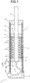
Fig. 1 is a longitudinal sectional view of a cylindrical linear motor according to one embodiment. -
Fig. 2 is a longitudinal sectional view of a teeth portion of the cylindrical linear motor according to one embodiment. -
Fig. 3 is a graph showing a relationship between a value obtained by dividing an axial length L2 of a permanent magnet of a sub magnetic pole by an axial length L1 of a permanent magnet of a main magnetic pole and a thrust of the cylindrical linear actuator. - Hereinafter, the present invention will be described based on the embodiments illustrated in the drawings. As shown in
Fig. 1 , a cylindricallinear motor 1 according to one embodiment includes acore 2 having acylindrical yoke 3 and a plurality ofannular teeth 4 provided on the outer periphery of theyoke 3; a winding 5 mounted between theteeth core 2 is inwardly inserted movably in the axial direction. - Hereinafter, each portion of the cylindrical
linear motor 1 will be described in details. Thecore 2 is configured to include acylindrical yoke 3; and a plurality ofteeth 4 which are annular and are provided on the outer periphery of theyoke 3 at intervals in the axial direction, and serve as a movable element. - The
yoke 3 has a cylindrical shape as described above, and the thickness thereof is secured so that the sectional area thereof is equal to or larger than an area of the cross section obtained by cutting theteeth 4 with said cylinder wherever from the inner periphery to the outer periphery of theteeth 4 with the cylinder around the axis A of the core 2 (seeFig. 2 ). - In the present embodiment, as shown in
Figs. 1 and2 , tenteeth 4 are provided on the outer periphery of theyoke 3 at equal intervals in the axial direction, and a slot 6 consisting of spaces in which awinding 5 is mounted between theteeth tooth 4 is annular and, except for theteeth 4 arranged at both ends of thecore 2, has an equal-leg trapezoidal shape in which the width Wo of the outerperipheral end 4a is smaller than the width Wi of the innerperipheral end 4b in the axial direction so that theside surfaces peripheral end 4a. Additionally, in theteeth 4 excluding theend teeth 4, an inner angle θ formed by aside surface core 2 in a cross section cut along a plane including the axis A of thecore 2 is set to an angle in the range of 6 degrees to 12 degrees. Note that as shown inFig. 2 , theend teeth 4 have a cross-sectional shape in which atooth 4 other than theend teeth 4 is cut in half on a plane orthogonal to the axis of thecore 2. Thus, the cross-sectional shape of eachtooth 4 is a trapezoidal shape in which the width of the outer peripheral end is smaller than the width of the inner peripheral end. - Furthermore, in the present embodiment, a total of nine slots 6 consisting of spaces are provided between the
adjacent teeth Fig. 1 . Additionally, this slot 6 is mounted with the winding 5 wound therearound. The winding 5 is a three-phase winding of U phase, V phase and W phase. The nine slots 6 are mounted with W phase and U phase, U phase, U phase, U phase and V phase, V phase, V phase, V phase and W phase, W phase andW phase windings 5 in order from the left side inFig. 1 . - Additionally, the
core 2 configured in this way is mounted on an outer periphery of arod 11 formed of a nonmagnetic material, which is an output shaft. Specifically, thecore 2 is fixed to therod 11 byannular stoppers rod 11 inFig. 1 . - On the other hand, the
field 7 is, in the present embodiment, configured to include anouter tube 8 formed of a cylindrical non-magnetic material; aninner tube 9 formed of a cylindrical non-magnetic material inserted into theouter tube 8; andpermanent magnets 10a of an annular main magnetic pole andpermanent magnets 10b of an annular sub magnetic pole, which are alternately stacked and inserted in the axial direction over the entire annular gap between theouter tube 8 and theinner tube 9. Note that the triangular marks described in thepermanent magnets 10a of the main magnetic pole and thepermanent magnets 10b of the sub magnetic pole inFig. 1 indicate the magnetization direction, the magnetization direction of thepermanent magnets 10a of the main magnetic pole is the radial direction, and the magnetization direction of thepermanent magnets 10b of the sub magnetic pole is the axial direction. Additionally, when thepermanent magnets 10a of the main magnetic pole and thepermanent magnets 10b of the sub magnetic pole are stacked, eachpermanent magnet field 7 in such a direction that a region from the center to the center of thepermanent magnets 10b of the sub magnetic pole on both sides sandwiching thepermanent magnet 10a of the main magnetic pole serves as one magnetic pole. That is, thepermanent magnets 10a of the main magnetic pole and thepermanent magnets 10b of the sub magnetic pole are arranged in a Halbach array, and the S poles and the N poles are arranged so as to appear alternately in the axial direction on the inner peripheral side of thefield 7. - In addition, the axial length L1 of the
permanent magnet 10a of the main magnetic pole is longer than the axial length L2 of thepermanent magnet 10b of the sub magnetic pole, and in the present embodiment, the axial length L1 of thepermanent magnet 10a of the main magnetic pole and the axial length L2 of thepermanent magnet 10b of the sub magnetic pole are set so as to satisfy 0.2 ≤ L2 / L1 ≤ 0.4. Since the magnetic resistance between thecore 2 and thepermanent magnet 10a of the main magnetic pole can be reduced and the magnetic field acting on thecore 2 can be increased by increasing the axial length of thepermanent magnet 10a of the main magnetic pole, the thrust of the cylindricallinear motor 1 can be improved. - Furthermore, the
permanent magnet 10b of the sub magnetic pole has a coercive force higher than that of thepermanent magnet 10a of the main magnetic pole. The residual magnetic flux density and the coercive force of a permanent magnet are closely related to each other, and they are generally in such a conflicting relationship with each other that increasing the residual magnetic flux density decreases the coercive force, and increasing the coercive force decreases the residual magnetic flux density. Since a large magnetic field is applied in the direction of demagnetization to thepermanent magnet 10b of the sub magnetic pole in the Halbach array, the coercive force of thepermanent magnet 10b of the sub magnetic pole is increased to suppress demagnetization so that a large magnetic field can act on thecore 2. On the other hand, the strength of the magnetic field acting on thecore 2 depends on the number of lines of magnetic force of thepermanent magnets 10a of the main magnetic pole. Therefore, a permanent magnet having a high residual magnetic flux density as thepermanent magnet 10a of the main magnetic pole is used so that a large magnetic field can act on thecore 2. In the present embodiment, when the coercive force of thepermanent magnet 10b of the sub magnetic pole is made higher than that of thepermanent magnet 10a of the main magnetic pole, the material of thepermanent magnet 10b of the sub magnetic pole is a material having a coercive force higher than that of the material of thepermanent magnet 10a of the main magnetic pole. Therefore, the combination of thepermanent magnet 10a of the main magnetic pole and thepermanent magnet 10b of the sub magnetic pole can be easily realized by selecting the materials. Note that in the present embodiment, thepermanent magnet 10a of the main magnetic pole is made of a material having a high residual magnetic flux density containing neodymium, iron, and boron as main components, and thepermanent magnet 10b of the sub magnetic pole is made of a magnet that is hard to demagnetize obtained by adding dysprosium to the material described above. - In addition, the
core 2 is inserted on the inner peripheral side of thefield 7, and thefield 7 causes a magnetic field to act on thecore 2. Note that since thefield 7 is only needed to cause a magnetic field to act on the movable range of thecore 2, it is only needed to determine the installation range of the permanent magnets 10 according to the movable range of thecore 2. Therefore, thepermanent magnets core 2 in the annular gap between theouter tube 8 and theinner tube 9. - In addition, the left end of the
outer tube 8 and theinner tube 9 inFig. 1 is closed by acap 14, and the right end of theouter tube 8 and theinner tube 9 inFig. 1 is closed by anannular rod guide 15 for guiding the axial movement of therod 11 inserted in the inner periphery. In addition,stoppers inner tube 9, and thestoppers core 2 to move smoothly in the axial direction together with therod 11 without axial displacement with respect to thefield 7. Additionally, theinner tube 9 plays a role to form a gap between the outer periphery of thecore 2 and the inner periphery of each of thepermanent magnets core 2 in cooperation with thestoppers - Note that the
cap 14 is provided with aconnector 14a for connecting the cable C connected to thewindings 5 to an external power supply (not shown), so that thewindings 5 can be energized from an external power supply. In addition, the axial length of theouter tube 8 and theinner tube 9 is longer than the axial length of thecore 2, and thecore 2 can stroke in the left and right directions inFig. 1 in a range of the axial length of thefield 7. - Additionally, for example, by sensing the electrical angle of the
winding 5 with respect to thefield 7, switching the energization phase based on the electrical angle and controlling the current amount of each winding 5 by PWM control, the thrust of the cylindricallinear motor 1 and the moving direction of thecore 2 can be controlled. Note that the control method described above is an example, and it is not limited thereto. Thus, in the cylindricallinear motor 1 of the present embodiment, thecore 2 is an armature and a movable element, and thefield 7 acts as a stator. In addition, when an external force that causes thecore 2 and thefield 7 to relatively displace in the axial direction is applied, the thrust for suppressing the relative displacement can be generated by energizing the winding 5 or an induced electromotive force generated in thewinding 5 to cause the cylindricallinear motor 1 to dampen the vibration and motion of the device due to the external force, and the energy regeneration that generates electric power from the external force is also possible. - As described above, the cylindrical
linear motor 1 of the present invention includes a cylindrical linear motor includes: acore 2 having acylindrical yoke 3, and a plurality ofteeth 4 that are annular and are provided at intervals in an axial direction on an outer periphery of theyoke 3; a winding 5 mounted in slots 6 between theteeth field 7 which is cylindrical and in which thecore 2 is inwardly inserted movably in the axial direction to arrange N poles and S poles alternately in the axial direction, wherein thefield 7 haspermanent magnets 10a of a main magnetic pole radially magnetized andpermanent magnets 10b of a sub magnetic pole axially magnetized that are alternately arranged in a Halbach array in the axial direction, an axial length L1 of thepermanent magnet 10a of the main magnetic pole is longer than an axial length L2 of thepermanent magnet 10b of the sub magnetic pole, and thepermanent magnet 10b of the sub magnetic pole has a coercive force higher than that of thepermanent magnet 10a of the main magnetic pole. - When the cylindrical
linear motor 1 is configured in this way, the axial length of thepermanent magnet 10a of the main magnetic pole can be increased, and the magnetic resistance between thepermanent magnet 10a of the main magnetic pole and thecore 2 can be reduced. Thus, the magnetic field acting on thecore 2 can be increased. Also, since thepermanent magnet 10b of the sub magnetic pole has a higher coercive force than thepermanent magnet 10a of the main magnetic pole, while suppressing the demagnetization of thepermanent magnet 10b of the sub magnetic pole to which a large magnetic field is applied, a permanent magnet having a high residual magnetic flux density can be used as thepermanent magnet 10a. - Therefore, according to the cylindrical
linear motor 1 of the present invention, the magnetic resistance between thepermanent magnet 10a of the main magnetic pole and thecore 2 can be reduced while suppressing the demagnetization of thepermanent magnet 10b of the sub magnetic pole, and the thrust can be effectively improved. - Note that the longer the axial length L1 of the
permanent magnet 10a of the main magnetic pole is longer than the axial length L2 of thepermanent magnet 10b of the sub magnetic pole, the more thefield 7 can apply a larger magnetic field to thecore 2, but the shorter the axial length of thepermanent magnet 10b of the sub magnetic pole is, the lower the coercive force is and the easier the demagnetization occurs. If thepermanent magnet 10b of the sub magnetic pole is demagnetized, the magnetic field of thefield 7 becomes small, and thus the demagnetization of thepermanent magnet 10b of the sub magnetic pole also affects the magnitude of the magnetic field. Therefore, in order to improve the thrust while avoiding demagnetization, there is an optimum relationship between the axial length L1 of thepermanent magnet 10a of the main magnetic pole and the axial length L2 of thepermanent magnet 10b of the sub magnetic pole.Fig. 3 shows the relationship between the value obtained by dividing the axial length L2 of thepermanent magnet 10b of the sub magnetic pole by the axial length L1 of thepermanent magnet 10a of the main magnetic pole and the thrust of the cylindricallinear actuator 1. As a result of extensive research, the inventors have found that, as shown inFig. 3 , if the axial length L1 of thepermanent magnet 10a of the main magnetic pole and the axial length L2 of thepermanent magnet 10b of the sub magnetic pole are set so as to satisfy 0.15 ≤ L2 / L1 ≤ 0.6, a thrust of 95% or more with respect to the thrust when the value of L2 / L1 is set to an ideal value can be secured, so that the thrust of the cylindricallinear motor 1 can be further improved while avoiding demagnetization. Therefore, if the axial length L1 of thepermanent magnet 10a of the main magnetic pole and the axial length L2 of thepermanent magnet 10b of the sub magnetic pole in the cylindricallinear motor 1 are set so as to satisfy 0.15 ≤ L2 / L1 ≤ 0.6, the thrust can be further improved while avoiding the demagnetization of thepermanent magnet 10b of the sub magnetic pole. Furthermore, as can be understood fromFig. 3 , when the axial length L1 of thepermanent magnet 10a of the main magnetic pole and the axial length L2 of thepermanent magnet 10b of the sub magnetic pole are set so as to satisfy 0.2 ≤ L2 / L1 ≤ 0.5, a thrust of 98% or more with respect to the thrust when the value of L2 / L1 is set to an ideal value can be secured, so that the thrust of the cylindricallinear motor 1 can be more effectively improved while avoiding demagnetization. - In addition, in the present embodiment, when making the coercive force of the
permanent magnet 10b of the sub magnetic pole higher than that of thepermanent magnet 10a of the main magnetic pole, the material of thepermanent magnet 10b of the sub magnetic pole is a material having a coercive force larger than that of the material of thepermanent magnet 10a of the main magnetic pole. Therefore, the combination of thepermanent magnet 10a of the main magnetic pole and thepermanent magnet 10b of the sub magnetic pole can be easily realized by selecting the materials. - Furthermore, since the cross-sectional shape of the
teeth 4 is a trapezoidal shape in which the width of the outer peripheral end is smaller than the width of the inner peripheral end in the cylindricallinear motor 1 of the present embodiment, the magnetic path cross-sectional area at the inner peripheral end is larger than that in the case of the cross-sectional shape of theteeth 4 being a rectangular shape. Therefore, since a large magnetic path cross-sectional area can be easily secured, magnetic saturation when thewindings 5 are energized can be suppressed, and a larger magnetic field can be generated in the cylindricallinear motor 1 configured in this way, a larger thrust can be generated. Note that theteeth 4 may have a trapezoidal cross-sectional shape in order to improve the thrust, but may have a rectangular cross-sectional shape or another shape. - Note that according to the research of the inventors, it was found that when the internal angle θ formed between the side surfaces 4c, 4d in the cross section of the
teeth 4 and the orthogonal plane O is in the range of 6 degrees to 12 degrees, a good mass thrust density can be obtained. Here, the mass thrust density is a value obtained by dividing the maximum thrust of the cylindricallinear motor 1 having the above-described configuration by the mass, and if the mass thrust density is improved, the thrust per mass of the cylindricallinear motor 1 increases. Therefore, a large thrust is obtained in the cylindricallinear motor 1 in which the internal angle θ formed between the side surfaces 4c, 4d in the cross section of theteeth 4 and the orthogonal plane O is in the range of 6 degrees to 12 degrees. - Although the preferred embodiments of the present invention have been described above in detail, modifications, variations and changes are possible without departing from the scope of the claims.
- This application claims priority based on Japanese Patent Application No.
2017-253631
Claims (4)
- A cylindrical linear motor comprising:a core having a cylindrical yoke, and a plurality of teeth that are annular and are provided at intervals in an axial direction on an outer periphery of the yoke;a winding mounted in slots between the teeth; anda field which is cylindrical and in which the core is inwardly inserted movably in the axial direction to arrange N poles and S poles alternately in the axial direction, whereinthe field has permanent magnets of a main magnetic pole radially magnetized and permanent magnets of a sub magnetic pole axially magnetized that are alternately arranged in a Halbach array in the axial direction,an axial length of the permanent magnet of the main magnetic pole is longer than an axial length of the permanent magnet of the sub magnetic pole, andthe permanent magnet of the sub magnetic pole has a coercive force higher than that of the permanent magnet of the main magnetic pole.
- The cylindrical linear motor according to claim 1, wherein
when the axial length of the permanent magnet of the main magnetic pole is L1 and the axial length of the permanent magnet of the sub magnetic pole is L2, the axial length of the permanent magnet of the main magnetic pole and the axial length of the permanent magnet of the sub magnetic pole are set so as to satisfy 0.15 ≤ L2 / L1 ≤ 0.6. - The cylindrical linear motor according to claim 2, wherein
when the axial length of the permanent magnet of the main magnetic pole is L1 and the axial length of the permanent magnet of the sub magnetic pole is L2, the axial length of the permanent magnet of the main magnetic pole and the axial length of the permanent magnet of the sub magnetic pole are set so as to satisfy 0.2 ≤ L2 / L1 ≤ 0.5. - The cylindrical linear motor according to claim 1, wherein
the permanent magnet of the sub magnetic pole is made of a material having a coercive force higher than that of the permanent magnet of the main magnetic pole.
Applications Claiming Priority (2)
| Application Number | Priority Date | Filing Date | Title |
|---|---|---|---|
| JP2017253631A JP2019122072A (en) | 2017-12-28 | 2017-12-28 | Cylindrical linear motor |
| PCT/JP2018/030278 WO2019130646A1 (en) | 2017-12-28 | 2018-08-14 | Cylindrical linear motor |
Publications (2)
| Publication Number | Publication Date |
|---|---|
| EP3734815A1 true EP3734815A1 (en) | 2020-11-04 |
| EP3734815A4 EP3734815A4 (en) | 2021-09-08 |
Family
ID=67066842
Family Applications (1)
| Application Number | Title | Priority Date | Filing Date |
|---|---|---|---|
| EP18896487.8A Withdrawn EP3734815A4 (en) | 2017-12-28 | 2018-08-14 | LINEAR CYLINDRICAL MOTOR |
Country Status (4)
| Country | Link |
|---|---|
| US (1) | US11245321B2 (en) |
| EP (1) | EP3734815A4 (en) |
| JP (1) | JP2019122072A (en) |
| WO (1) | WO2019130646A1 (en) |
Families Citing this family (1)
| Publication number | Priority date | Publication date | Assignee | Title |
|---|---|---|---|---|
| FI20235881A1 (en) * | 2023-08-09 | 2025-02-10 | Lekatech Oy | A mover for a tubular linear induction machine |
Family Cites Families (14)
| Publication number | Priority date | Publication date | Assignee | Title |
|---|---|---|---|---|
| AU672954B2 (en) * | 1991-07-12 | 1996-10-24 | Denne Developments Limited | Electromagnetic apparatus for producing linear motion |
| JP3824060B2 (en) * | 2001-10-16 | 2006-09-20 | 株式会社安川電機 | Linear motor |
| US7378763B2 (en) * | 2003-03-10 | 2008-05-27 | Höganäs Ab | Linear motor |
| JP2007019127A (en) | 2005-07-06 | 2007-01-25 | Yaskawa Electric Corp | Periodic magnetic field generator and linear motor using the same |
| JP5188357B2 (en) * | 2008-10-23 | 2013-04-24 | 三菱電機株式会社 | Linear motor |
| JP5422175B2 (en) * | 2008-11-05 | 2014-02-19 | 三菱重工業株式会社 | Linear actuator |
| JP5370912B2 (en) * | 2008-12-04 | 2013-12-18 | 日立金属株式会社 | Magnetic field generator |
| CN103534900B (en) * | 2011-07-08 | 2016-01-20 | 三菱电机株式会社 | Permanet magnet type rotary electric machine and manufacture method thereof |
| JP2013062889A (en) * | 2011-09-10 | 2013-04-04 | Nidec Servo Corp | Brushless dc motor |
| JP2013106458A (en) * | 2011-11-15 | 2013-05-30 | Yaskawa Electric Corp | Linear motor |
| KR101407854B1 (en) * | 2012-12-03 | 2014-06-16 | 뉴모텍(주) | Motor with Variable Magnet Flux |
| WO2015072328A1 (en) | 2013-11-12 | 2015-05-21 | 日立金属株式会社 | Magnetic-field generation device and linear motor |
| JP2016029880A (en) * | 2014-07-18 | 2016-03-03 | 日立金属株式会社 | Magnet unit and method of manufacturing magnet unit |
| JP2016152668A (en) * | 2015-02-17 | 2016-08-22 | 住友重機械工業株式会社 | Linear motor, magnet unit, stage device |
-
2017
- 2017-12-28 JP JP2017253631A patent/JP2019122072A/en active Pending
-
2018
- 2018-08-14 US US16/636,744 patent/US11245321B2/en active Active
- 2018-08-14 WO PCT/JP2018/030278 patent/WO2019130646A1/en not_active Ceased
- 2018-08-14 EP EP18896487.8A patent/EP3734815A4/en not_active Withdrawn
Also Published As
| Publication number | Publication date |
|---|---|
| WO2019130646A1 (en) | 2019-07-04 |
| EP3734815A4 (en) | 2021-09-08 |
| US20200244153A1 (en) | 2020-07-30 |
| JP2019122072A (en) | 2019-07-22 |
| US11245321B2 (en) | 2022-02-08 |
Similar Documents
| Publication | Publication Date | Title |
|---|---|---|
| EP2424088A2 (en) | Linear motor | |
| JP2019187218A (en) | Cylindrical linear motor | |
| US20210313867A1 (en) | Tubular linear motor | |
| US12131853B2 (en) | Apparatus for manufacturing rotor, method of manufacturing rotor, and rotor | |
| JP7228179B2 (en) | Cylindrical linear motor | |
| US11245321B2 (en) | Cylindrical linear motor | |
| JP2022007249A (en) | Tubular linear motor | |
| JP2019187226A (en) | Cylindrical linear motor | |
| JP2019187215A (en) | Cylindrical linear motor | |
| JP6990143B2 (en) | Cylindrical linear motor | |
| JP2019187212A (en) | Cylindrical linear motor | |
| JP7482480B2 (en) | Cylindrical Linear Motor | |
| WO2019202765A1 (en) | Cylindrical linear motor | |
| WO2019102761A1 (en) | Tubular linear motor | |
| US11456654B2 (en) | Tubular linear motor | |
| JP7274852B2 (en) | Cylindrical linear motor | |
| JP7036317B2 (en) | Cylindrical linear motor | |
| JP2019187216A (en) | Cylindrical linear motor | |
| JP7252834B2 (en) | Cylindrical linear motor | |
| JP7186956B2 (en) | Cylindrical linear motor and method for manufacturing annular magnet | |
| JP7716713B2 (en) | cylindrical linear motor | |
| KR100928554B1 (en) | Stator for industrial and high speed motors | |
| JP7569534B2 (en) | Cylindrical Linear Motor | |
| WO2025013492A1 (en) | Cylindrical linear motor | |
| JP2021083163A (en) | Tubular linear motor |
Legal Events
| Date | Code | Title | Description |
|---|---|---|---|
| STAA | Information on the status of an ep patent application or granted ep patent |
Free format text: STATUS: THE INTERNATIONAL PUBLICATION HAS BEEN MADE |
|
| PUAI | Public reference made under article 153(3) epc to a published international application that has entered the european phase |
Free format text: ORIGINAL CODE: 0009012 |
|
| STAA | Information on the status of an ep patent application or granted ep patent |
Free format text: STATUS: REQUEST FOR EXAMINATION WAS MADE |
|
| 17P | Request for examination filed |
Effective date: 20200331 |
|
| AK | Designated contracting states |
Kind code of ref document: A1 Designated state(s): AL AT BE BG CH CY CZ DE DK EE ES FI FR GB GR HR HU IE IS IT LI LT LU LV MC MK MT NL NO PL PT RO RS SE SI SK SM TR |
|
| AX | Request for extension of the european patent |
Extension state: BA ME |
|
| DAV | Request for validation of the european patent (deleted) | ||
| DAX | Request for extension of the european patent (deleted) | ||
| A4 | Supplementary search report drawn up and despatched |
Effective date: 20210811 |
|
| RIC1 | Information provided on ipc code assigned before grant |
Ipc: H02K 1/27 20060101ALN20210805BHEP Ipc: H02K 1/17 20060101ALN20210805BHEP Ipc: H02K 41/03 20060101AFI20210805BHEP |
|
| STAA | Information on the status of an ep patent application or granted ep patent |
Free format text: STATUS: EXAMINATION IS IN PROGRESS |
|
| 17Q | First examination report despatched |
Effective date: 20230202 |
|
| STAA | Information on the status of an ep patent application or granted ep patent |
Free format text: STATUS: THE APPLICATION HAS BEEN WITHDRAWN |
|
| 18W | Application withdrawn |
Effective date: 20230315 |