EP3734807A1 - Generator field amortisseur & spring locking mechanism - Google Patents
Generator field amortisseur & spring locking mechanism Download PDFInfo
- Publication number
- EP3734807A1 EP3734807A1 EP20171436.7A EP20171436A EP3734807A1 EP 3734807 A1 EP3734807 A1 EP 3734807A1 EP 20171436 A EP20171436 A EP 20171436A EP 3734807 A1 EP3734807 A1 EP 3734807A1
- Authority
- EP
- European Patent Office
- Prior art keywords
- amortisseur
- spring assembly
- spring
- pin
- aperture
- Prior art date
- Legal status (The legal status is an assumption and is not a legal conclusion. Google has not performed a legal analysis and makes no representation as to the accuracy of the status listed.)
- Pending
Links
Images

Classifications
-
- F—MECHANICAL ENGINEERING; LIGHTING; HEATING; WEAPONS; BLASTING
- F16—ENGINEERING ELEMENTS AND UNITS; GENERAL MEASURES FOR PRODUCING AND MAINTAINING EFFECTIVE FUNCTIONING OF MACHINES OR INSTALLATIONS; THERMAL INSULATION IN GENERAL
- F16F—SPRINGS; SHOCK-ABSORBERS; MEANS FOR DAMPING VIBRATION
- F16F13/00—Units comprising springs of the non-fluid type as well as vibration-dampers, shock-absorbers, or fluid springs
-
- H—ELECTRICITY
- H02—GENERATION; CONVERSION OR DISTRIBUTION OF ELECTRIC POWER
- H02K—DYNAMO-ELECTRIC MACHINES
- H02K15/00—Processes or apparatus specially adapted for manufacturing, assembling, maintaining or repairing of dynamo-electric machines
- H02K15/02—Processes or apparatus specially adapted for manufacturing, assembling, maintaining or repairing of dynamo-electric machines of stator or rotor bodies
-
- H—ELECTRICITY
- H02—GENERATION; CONVERSION OR DISTRIBUTION OF ELECTRIC POWER
- H02K—DYNAMO-ELECTRIC MACHINES
- H02K1/00—Details of the magnetic circuit
- H02K1/06—Details of the magnetic circuit characterised by the shape, form or construction
- H02K1/22—Rotating parts of the magnetic circuit
- H02K1/28—Means for mounting or fastening rotating magnetic parts on to, or to, the rotor structures
- H02K1/30—Means for mounting or fastening rotating magnetic parts on to, or to, the rotor structures using intermediate parts, e.g. spiders
-
- F—MECHANICAL ENGINEERING; LIGHTING; HEATING; WEAPONS; BLASTING
- F16—ENGINEERING ELEMENTS AND UNITS; GENERAL MEASURES FOR PRODUCING AND MAINTAINING EFFECTIVE FUNCTIONING OF MACHINES OR INSTALLATIONS; THERMAL INSULATION IN GENERAL
- F16F—SPRINGS; SHOCK-ABSORBERS; MEANS FOR DAMPING VIBRATION
- F16F15/00—Suppression of vibrations in systems; Means or arrangements for avoiding or reducing out-of-balance forces, e.g. due to motion
- F16F15/02—Suppression of vibrations of non-rotating, e.g. reciprocating systems; Suppression of vibrations of rotating systems by use of members not moving with the rotating systems
- F16F15/04—Suppression of vibrations of non-rotating, e.g. reciprocating systems; Suppression of vibrations of rotating systems by use of members not moving with the rotating systems using elastic means
-
- H—ELECTRICITY
- H02—GENERATION; CONVERSION OR DISTRIBUTION OF ELECTRIC POWER
- H02K—DYNAMO-ELECTRIC MACHINES
- H02K11/00—Structural association of dynamo-electric machines with electric components or with devices for shielding, monitoring or protection
- H02K11/20—Structural association of dynamo-electric machines with electric components or with devices for shielding, monitoring or protection for measuring, monitoring, testing, protecting or switching
-
- H—ELECTRICITY
- H02—GENERATION; CONVERSION OR DISTRIBUTION OF ELECTRIC POWER
- H02K—DYNAMO-ELECTRIC MACHINES
- H02K3/00—Details of windings
- H02K3/04—Windings characterised by the conductor shape, form or construction, e.g. with bar conductors
- H02K3/12—Windings characterised by the conductor shape, form or construction, e.g. with bar conductors arranged in slots
- H02K3/16—Windings characterised by the conductor shape, form or construction, e.g. with bar conductors arranged in slots for auxiliary purposes, e.g. damping or commutating
-
- H—ELECTRICITY
- H02—GENERATION; CONVERSION OR DISTRIBUTION OF ELECTRIC POWER
- H02K—DYNAMO-ELECTRIC MACHINES
- H02K3/00—Details of windings
- H02K3/46—Fastening of windings on the stator or rotor structure
- H02K3/52—Fastening salient pole windings or connections thereto
- H02K3/527—Fastening salient pole windings or connections thereto applicable to rotors only
-
- H—ELECTRICITY
- H02—GENERATION; CONVERSION OR DISTRIBUTION OF ELECTRIC POWER
- H02K—DYNAMO-ELECTRIC MACHINES
- H02K7/00—Arrangements for handling mechanical energy structurally associated with dynamo-electric machines, e.g. structural association with mechanical driving motors or auxiliary dynamo-electric machines
- H02K7/003—Couplings; Details of shafts
-
- H—ELECTRICITY
- H02—GENERATION; CONVERSION OR DISTRIBUTION OF ELECTRIC POWER
- H02K—DYNAMO-ELECTRIC MACHINES
- H02K7/00—Arrangements for handling mechanical energy structurally associated with dynamo-electric machines, e.g. structural association with mechanical driving motors or auxiliary dynamo-electric machines
- H02K7/18—Structural association of electric generators with mechanical driving motors, e.g. with turbines
- H02K7/1807—Rotary generators
-
- H—ELECTRICITY
- H02—GENERATION; CONVERSION OR DISTRIBUTION OF ELECTRIC POWER
- H02K—DYNAMO-ELECTRIC MACHINES
- H02K7/00—Arrangements for handling mechanical energy structurally associated with dynamo-electric machines, e.g. structural association with mechanical driving motors or auxiliary dynamo-electric machines
- H02K7/18—Structural association of electric generators with mechanical driving motors, e.g. with turbines
- H02K7/1807—Rotary generators
- H02K7/1823—Rotary generators structurally associated with turbines or similar engines
-
- H—ELECTRICITY
- H02—GENERATION; CONVERSION OR DISTRIBUTION OF ELECTRIC POWER
- H02K—DYNAMO-ELECTRIC MACHINES
- H02K7/00—Arrangements for handling mechanical energy structurally associated with dynamo-electric machines, e.g. structural association with mechanical driving motors or auxiliary dynamo-electric machines
- H02K7/18—Structural association of electric generators with mechanical driving motors, e.g. with turbines
- H02K7/1807—Rotary generators
- H02K7/1823—Rotary generators structurally associated with turbines or similar engines
- H02K7/183—Rotary generators structurally associated with turbines or similar engines wherein the turbine is a wind turbine
-
- H—ELECTRICITY
- H02—GENERATION; CONVERSION OR DISTRIBUTION OF ELECTRIC POWER
- H02K—DYNAMO-ELECTRIC MACHINES
- H02K3/00—Details of windings
- H02K3/42—Means for preventing or reducing eddy-current losses in the winding heads, e.g. by shielding
-
- H—ELECTRICITY
- H02—GENERATION; CONVERSION OR DISTRIBUTION OF ELECTRIC POWER
- H02K—DYNAMO-ELECTRIC MACHINES
- H02K3/00—Details of windings
- H02K3/46—Fastening of windings on the stator or rotor structure
- H02K3/48—Fastening of windings on the stator or rotor structure in slots
- H02K3/487—Slot-closing devices
-
- Y—GENERAL TAGGING OF NEW TECHNOLOGICAL DEVELOPMENTS; GENERAL TAGGING OF CROSS-SECTIONAL TECHNOLOGIES SPANNING OVER SEVERAL SECTIONS OF THE IPC; TECHNICAL SUBJECTS COVERED BY FORMER USPC CROSS-REFERENCE ART COLLECTIONS [XRACs] AND DIGESTS
- Y02—TECHNOLOGIES OR APPLICATIONS FOR MITIGATION OR ADAPTATION AGAINST CLIMATE CHANGE
- Y02E—REDUCTION OF GREENHOUSE GAS [GHG] EMISSIONS, RELATED TO ENERGY GENERATION, TRANSMISSION OR DISTRIBUTION
- Y02E20/00—Combustion technologies with mitigation potential
- Y02E20/16—Combined cycle power plant [CCPP], or combined cycle gas turbine [CCGT]
Definitions
- the present application and the resultant patent relate generally to electrical generators and more particularly relate to electrical generators used in combined cycle systems and the like with a locking mechanism for an amortisseur-spring assembly to prevent component migration.
- Generator fields may have an amortisseur system designed to conduct unintended rotor surface currents. Such rotor surface currents may be generated during motored startup, normal operation, and abnormal operation.
- the amortisseur system may be an assembly of thin metallic conductive parts positioned in the rotor wedge dovetail.
- Amortisseur systems designed for static starts i.e., motored starts
- These components may migrate axially over long term cyclic (start and thermal) operations. Such migration may result in blocked ventilation and/or electrical ground faults in service, i.e., the electrical insulation to the charged windings may become compromised. Given such, axial retention of the components of an amortisseur system may promote long term reliability and performance.
- the present application and the resultant patent thus provide an amortisseur-spring assembly for use about at least one of a wedge and a retaining ring of a generator.
- the amortisseur-spring assembly may include an amortisseur, a spring, a creepage block, and a locking mechanism extending through the amortisseur, the spring, and the creepage block.
- the present application and the resultant patent further provide a method of installing an amortisseur-spring assembly in a generator.
- the method may include the steps of creating an aperture through an amortisseur, a spring, and a creepage block of the amortisseur-spring assembly, inserting a locking mechanism in the aperture, and positioning the amortisseur-spring assembly adjacent to at least one of a wedge and a retaining ring of the generator.
- the present application and the resultant patent further provide an amortisseur-spring assembly for use about at least one of a wedge and a retaining ring of a generator.
- the amortisseur-spring assembly may include an amortisseur, a spring, a creepage block, and a pin extending through the amortisseur, the spring, and the creepage block.
- the pin may be positioned adjacent to the wedge or the retaining ring.
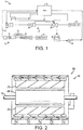
- Fig. 1 is a schematic diagram of an exemplary embodiment of a combined cycle power generation system 10.
- the combined cycle power generation system 10 may include a gas turbine, a steam turbine, and a heat recovery steam generator (HRSG).
- the combined cycle system 10 may include a gas turbine 12 for driving a first generator 14 to produce electrical power.
- the gas turbine 12 may include a turbine 16, a combustor 18, and a compressor 20.
- the combined cycle system 10 also may include a steam turbine 22 for driving a second generator 24.
- the steam turbine 22 may include a low-pressure section 26 (LP ST), an intermediate-pressure section 28 (IP ST), and a high-pressure section 30 (HP ST).
- LP ST low-pressure section 26
- IP ST intermediate-pressure section 28
- HP ST high-pressure section 30
- gas turbine 12 and the steam turbine 22 may drive separate generators 14 and 24 as is shown herein, the gas turbine 12 and the steam turbine 22 also may be utilized in tandem to drive a single load via a single shaft.
- the generators and components described herein and the like may be incorporated into other types of power generation systems.
- the combined cycle system 10 also may include a multi-stage heat recovery steam generator 32.
- Heated exhaust gas 34 from the gas turbine 12 may be directed into the heat recovery steam generator 32 to heat the steam used to power the steam turbine 22.
- Exhaust from the low-pressure section 26 of the steam turbine 22 may be directed into a condenser 36.
- Condensate from the condenser 36 may, in turn, be directed into a low-pressure section of the heat recovery steam generator 32 with the aid of a condensate pump 38.
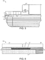
- Fig. 2 is a sectional view of an example of a generator 64 that may serve as the generator 14 and/or the generator 24 in the combined cycle power generation system 10 of Fig. 1 or in various other types of power generation systems.
- the generator 64 may include an annular frame 66, a rotor 68, a stator 70, and a shaft 72.
- the shaft 72 may be driven to rotate by a gas turbine, a steam turbine, a wind turbine, a hydro turbine, an internal combustion engine, or any other suitable device configured to provide a rotational output.
- the shaft 72 may be coupled to a substantially cylindrical rotor 68 that may include a wire winding about a magnetic core.
- the rotor 68 may be disposed within the stator 70, which is configured to provide a stationary magnetic field.
- Rotation of the rotor 68 within the stator 70 generates electrical current within the wire winding, thereby producing an electrical output from the generator 64.
- high cyclic duty of the generator 64 may lead to performance degradations of the generator 64 and the components therein over time.
- Fig. 3 is a plan view of an embodiment of the generator rotor 68 of the generator 64 of Fig. 2 .
- the rotor 68 may include the shaft 72 with a coupling 90, such as a mechanical mode or power turbine coupling, on one end.
- the shaft extends in an axial direction 86 and rotates the rotor 68 in a circumferential direction 88.
- the rotor 68 extends out from the shaft 72 in a radial direction 90.
- On the other end of the shaft 72 there may be collector rings 92 thereon to provide an electrical junction for the rotor field windings.
- a collector fan 94 may be located adjacent to the collector rings 92.
- the rotor 68 may have a large diameter body 96 that holds coil windings 98.
- the coil windings 98 may be disposed in axially oriented 86 slots that extend radially 90 outward from the middle of the rotor 68 to the axial 86 ends of the rotor body 96.
- Figs. 4-6 show an amortisseur-spring assembly 100 for use with the rotor 68 and the like.
- the amortisseur-spring assembly 100 may be positioned between a retaining ring 102 and wedges 104 above the windings 98 of the rotor 68 and between a glass filler 106 and ring insulation 108.
- the amortisseur-spring assembly 100 may include an amortisseur 110, a spring 112, and a creepage block 114.
- the creepage block 114 and the windings 98 may be somewhat loose such that the creepage block 114 may shift axially.
- At rated speed of the generator 64 all of the components may be compressed radially outward by the developing centrifugal force. As the electrical field is excited and the current is ramped up to rated output, the windings 98 may heat up and expand axially.
- the components herein thus may slide axially depending upon the relative coefficients of friction until an axial stop is reached.
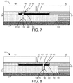
- Figs. 7 and 8 show examples of an amortisseur-spring assembly 120 as may be described herein.
- the amortisseur-spring assembly 120 may include the amortisseur 110, the spring 112, and the creepage block 114 as described above.
- the amortisseur-spring assembly 120 also may include a locking mechanism 130.
- the locking mechanism 130 may take the form of a pin 140 or other type of mechanical closure.
- the pin 140 may be made out of a metallic such as steel or a non-metallic such as a glass epoxy and the like.
- the pin 140 may have a stepped configuration with a shaft 150 and a head 160. The diameter of the head 160 may be greater than the diameter of the shaft 160.
- the pin 140 may extend through an aperture 170 drilled or otherwise created through each of the components of the amortisseur-spring assembly 100. Specifically, an amortisseur aperture 180, a spring aperture 190, and a creep block aperture 200 may be created. The amortisseur aperture 180 may be larger in diameter than the spring aperture 190 and the creep block aperture 200 given the relative sizes of the shaft 150 and the head 160 of the pin 140. Other components and other configurations may be used herein.
- the pin 140 and the aperture 170 may be positioned under the wedges 104.
- the pin 140 and the aperture 170 may be positioned under the retaining ring 102, where it covers the rotor forging.
- the pin 140 should not be positioned over or adjacent to any of the radial ventilation holes in the components. Rather, the pin 140 and the aperture 170 are located in a previously solid section of the components.
- the pin 140 and the aperture 170 may be used under either wedge 104 in a wedge/wedge configuration. Other components and other configurations may be used herein.
- the pin 140 axially locks together the amortisseur 110, the spring 112, and the creepage block 114 to prevent relative motion between the components.
- the amortisseur aperture 180 and the diameter of the pin 140 in the amortisseur 110 is larger than that in the spring 112 and creepage block 114.
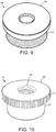
- Figs. 9-11 show alternative embodiments of the pin 140.
- the head 160, and/or the shaft 150, and/or the amortisseur aperture 180 may have threads 210 thereon such that the pin 140 may be radially locked and removed by torque through the threads 210.
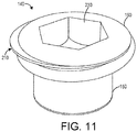
- the pin 140 may have an internal structure such as internal threads 220 as is shown in Fig. 10 or a drive 230 such as a hex drive or a slotted drive as is shown in Fig. 11 for easy removal/disassembly for maintenance.
- the pin 140 also may have a ribbed, knurled, or raised surface 240 as is also shown in Fig. 10 that acts to interfere with the amortisseur 110 to create an interference fit that locks the components together.
- the aperture 170 may have companion locking features therein. Additionally, the pin 140 may be locked into the amortisseur 110 or the creepage block 114 through an adhesive or epoxy and the like. Additionally, the pin 140 may be located to the amortisseur 110 through a brazing or welding process. Other components and other configurations may be used herein.
- part migration may be mitigated without requiring the capability to restrain the massive thermal forces seen in service.
- the source of the forces driving the migration is removed, i.e ., relative friction and relative motion between the creepage block 114 and the spring 112 and/or the amortisseur 110.
- the pin 140 By locating the pin 140 away from the ventilation holes, several benefits exist: (1) the pin material need not be made of non-conducting material which allows for higher strength and more readily available parts; (2) the pin 140 may be located in a more accessible location for assembly/disassembly (such as the retaining ring shrink fit position), which makes assembly and disassembly much easier for technician; and (3) external threads 210 or internal threads 220 and the other structures described above may be incorporated to facilitate positive locking and easy removal. Also, this solution allows for reuse of almost all parts (in most cases) and may be implemented by modifying (drilling) the amortisseur 110, the spring 112, and the creepage block 114, and procuring a quickly available and low cost pin 140. Given such, this may be implemented on jobs with short cycle times and at relatively low costs. This solution also may be applied to different model types with minimal redesign efforts.
- amortisseur-spring assembly 120 has been described in the context of the combined cycle power generation system 20, the assembly is equally applicable to simple cycle gas turbine generators and the like. Other types of generators also may be used herein.
Landscapes
- Engineering & Computer Science (AREA)
- Power Engineering (AREA)
- General Engineering & Computer Science (AREA)
- Mechanical Engineering (AREA)
- Physics & Mathematics (AREA)
- Acoustics & Sound (AREA)
- Aviation & Aerospace Engineering (AREA)
- Manufacturing & Machinery (AREA)
- Microelectronics & Electronic Packaging (AREA)
- Life Sciences & Earth Sciences (AREA)
- Sustainable Development (AREA)
- Sustainable Energy (AREA)
- Connection Of Motors, Electrical Generators, Mechanical Devices, And The Like (AREA)
- Windings For Motors And Generators (AREA)
- Insulation, Fastening Of Motor, Generator Windings (AREA)
- Iron Core Of Rotating Electric Machines (AREA)
Abstract
Description
- The present application and the resultant patent relate generally to electrical generators and more particularly relate to electrical generators used in combined cycle systems and the like with a locking mechanism for an amortisseur-spring assembly to prevent component migration.
- Generator fields may have an amortisseur system designed to conduct unintended rotor surface currents. Such rotor surface currents may be generated during motored startup, normal operation, and abnormal operation. The amortisseur system may be an assembly of thin metallic conductive parts positioned in the rotor wedge dovetail. Amortisseur systems designed for static starts (i.e., motored starts) also may have a spring to provide positive contact during low speed operation. These components may migrate axially over long term cyclic (start and thermal) operations. Such migration may result in blocked ventilation and/or electrical ground faults in service, i.e., the electrical insulation to the charged windings may become compromised. Given such, axial retention of the components of an amortisseur system may promote long term reliability and performance.
- The present application and the resultant patent thus provide an amortisseur-spring assembly for use about at least one of a wedge and a retaining ring of a generator. The amortisseur-spring assembly may include an amortisseur, a spring, a creepage block, and a locking mechanism extending through the amortisseur, the spring, and the creepage block.
- The present application and the resultant patent further provide a method of installing an amortisseur-spring assembly in a generator. The method may include the steps of creating an aperture through an amortisseur, a spring, and a creepage block of the amortisseur-spring assembly, inserting a locking mechanism in the aperture, and positioning the amortisseur-spring assembly adjacent to at least one of a wedge and a retaining ring of the generator.
- The present application and the resultant patent further provide an amortisseur-spring assembly for use about at least one of a wedge and a retaining ring of a generator. The amortisseur-spring assembly may include an amortisseur, a spring, a creepage block, and a pin extending through the amortisseur, the spring, and the creepage block. The pin may be positioned adjacent to the wedge or the retaining ring.
- These and other features and improvements of the present application and the resultant patent will become apparent to one of ordinary skill in the art upon review of the following detailed description when taken in conjunction with the several drawings and the appended claims.
-
-
Fig. 1 is a schematic diagram of an exemplary gas turbine combined cycle system as may be described herein. -
Fig. 2 is a sectional view of an exemplary generator for use in the gas turbine combined cycle system ofFig. 1 . -
Fig. 3 is a plan view of an exemplary generator rotor of the generator ofFig. 2 . -
Fig. 4 is partial plan view of an amortisseur system for use with the generator rotor ofFig. 3 -
Fig. 5 is a side view of the amortisseur system ofFig. 4 . -
Fig. 6 is a schematic diagram of the amortisseur system ofFig. 4 . -
Fig. 7 is a schematic diagram of an amortisseur system as may be described herein. -
Fig. 8 is a schematic diagram of an alternative embodiment of an amortisseur system as may be described herein. -
Fig. 9 is a perspective view of a pin for use with the amortisseur systems ofFigs. 7 and 8 . -
Fig. 10 is a perspective view of an alternative embodiment of a pin for use with the amortisseur systems ofFigs. 7 and 8 . -
Fig. 11 is a perspective view of an alternative embodiment of a pin for use with the amortisseur systems ofFigs. 7 and 8 . - Referring now to the drawings, in which like numerals refer to like elements throughout the several views,
Fig. 1 is a schematic diagram of an exemplary embodiment of a combined cyclepower generation system 10. The combined cyclepower generation system 10 may include a gas turbine, a steam turbine, and a heat recovery steam generator (HRSG). Specifically, the combinedcycle system 10 may include agas turbine 12 for driving afirst generator 14 to produce electrical power. Thegas turbine 12 may include aturbine 16, acombustor 18, and acompressor 20. The combinedcycle system 10 also may include asteam turbine 22 for driving asecond generator 24. Thesteam turbine 22 may include a low-pressure section 26 (LP ST), an intermediate-pressure section 28 (IP ST), and a high-pressure section 30 (HP ST). Although thegas turbine 12 and thesteam turbine 22 may driveseparate generators gas turbine 12 and thesteam turbine 22 also may be utilized in tandem to drive a single load via a single shaft. The generators and components described herein and the like may be incorporated into other types of power generation systems. - The combined
cycle system 10 also may include a multi-stage heatrecovery steam generator 32. Heatedexhaust gas 34 from thegas turbine 12 may be directed into the heatrecovery steam generator 32 to heat the steam used to power thesteam turbine 22. Exhaust from the low-pressure section 26 of thesteam turbine 22 may be directed into acondenser 36. Condensate from thecondenser 36 may, in turn, be directed into a low-pressure section of the heatrecovery steam generator 32 with the aid of acondensate pump 38. -
Fig. 2 is a sectional view of an example of agenerator 64 that may serve as thegenerator 14 and/or thegenerator 24 in the combined cyclepower generation system 10 ofFig. 1 or in various other types of power generation systems. Thegenerator 64 may include anannular frame 66, arotor 68, astator 70, and ashaft 72. Theshaft 72 may be driven to rotate by a gas turbine, a steam turbine, a wind turbine, a hydro turbine, an internal combustion engine, or any other suitable device configured to provide a rotational output. Theshaft 72 may be coupled to a substantiallycylindrical rotor 68 that may include a wire winding about a magnetic core. Therotor 68 may be disposed within thestator 70, which is configured to provide a stationary magnetic field. Rotation of therotor 68 within thestator 70 generates electrical current within the wire winding, thereby producing an electrical output from thegenerator 64. As described above, high cyclic duty of thegenerator 64 may lead to performance degradations of thegenerator 64 and the components therein over time. -
Fig. 3 is a plan view of an embodiment of thegenerator rotor 68 of thegenerator 64 ofFig. 2 . As is shown, therotor 68 may include theshaft 72 with acoupling 90, such as a mechanical mode or power turbine coupling, on one end. The shaft extends in anaxial direction 86 and rotates therotor 68 in acircumferential direction 88. Further, therotor 68 extends out from theshaft 72 in aradial direction 90. On the other end of theshaft 72, there may becollector rings 92 thereon to provide an electrical junction for the rotor field windings. Acollector fan 94 may be located adjacent to thecollector rings 92. Therotor 68 may have alarge diameter body 96 that holdscoil windings 98. Thecoil windings 98 may be disposed in axially oriented 86 slots that extend radially 90 outward from the middle of therotor 68 to the axial 86 ends of therotor body 96. -
Figs. 4-6 show an amortisseur-spring assembly 100 for use with therotor 68 and the like. The amortisseur-spring assembly 100 may be positioned between aretaining ring 102 andwedges 104 above thewindings 98 of therotor 68 and between aglass filler 106 andring insulation 108. The amortisseur-spring assembly 100 may include anamortisseur 110, aspring 112, and acreepage block 114. At turning speed/low speed of thegenerator 64, thecreepage block 114 and thewindings 98 may be somewhat loose such that thecreepage block 114 may shift axially. At rated speed of thegenerator 64, all of the components may be compressed radially outward by the developing centrifugal force. As the electrical field is excited and the current is ramped up to rated output, thewindings 98 may heat up and expand axially. The components herein thus may slide axially depending upon the relative coefficients of friction until an axial stop is reached. -
Figs. 7 and 8 show examples of an amortisseur-spring assembly 120 as may be described herein. The amortisseur-spring assembly 120 may include theamortisseur 110, thespring 112, and thecreepage block 114 as described above. The amortisseur-spring assembly 120 also may include a locking mechanism 130. The locking mechanism 130 may take the form of apin 140 or other type of mechanical closure. Thepin 140 may be made out of a metallic such as steel or a non-metallic such as a glass epoxy and the like. Thepin 140 may have a stepped configuration with ashaft 150 and ahead 160. The diameter of thehead 160 may be greater than the diameter of theshaft 160. Thepin 140 may extend through anaperture 170 drilled or otherwise created through each of the components of the amortisseur-spring assembly 100. Specifically, anamortisseur aperture 180, aspring aperture 190, and acreep block aperture 200 may be created. Theamortisseur aperture 180 may be larger in diameter than thespring aperture 190 and thecreep block aperture 200 given the relative sizes of theshaft 150 and thehead 160 of thepin 140. Other components and other configurations may be used herein. - As is shown in
Fig. 7 , thepin 140 and theaperture 170 may be positioned under thewedges 104. Alternatively as is shown inFig. 8 , thepin 140 and theaperture 170 may be positioned under the retainingring 102, where it covers the rotor forging. Thepin 140 should not be positioned over or adjacent to any of the radial ventilation holes in the components. Rather, thepin 140 and theaperture 170 are located in a previously solid section of the components. Further, instead of thewedges 104 and the retainingring 102 configuration shown herein, thepin 140 and theaperture 170 may be used under eitherwedge 104 in a wedge/wedge configuration. Other components and other configurations may be used herein. - The
pin 140 axially locks together theamortisseur 110, thespring 112, and thecreepage block 114 to prevent relative motion between the components. As is described above, theamortisseur aperture 180 and the diameter of thepin 140 in theamortisseur 110 is larger than that in thespring 112 andcreepage block 114. This stepped diameter in thepin 140, along with thewedges 104 being located over theamortisseur 110, acts to radially lock thepin 140 in place. This is significant, because the clearance in the slot, and therefore the radial travel of thecreepage block 114, often exceeds the thickness of the amortisseur 110 (and therefore engagement of thepin 140 into the amortisseur 110). Without this radial retention, thepin 140 may disengage from the components while the unit is on turning gear. -
Figs. 9-11 show alternative embodiments of thepin 140. Thehead 160, and/or theshaft 150, and/or theamortisseur aperture 180 may havethreads 210 thereon such that thepin 140 may be radially locked and removed by torque through thethreads 210. Likewise, thepin 140 may have an internal structure such asinternal threads 220 as is shown inFig. 10 or adrive 230 such as a hex drive or a slotted drive as is shown inFig. 11 for easy removal/disassembly for maintenance. Thepin 140 also may have a ribbed, knurled, or raisedsurface 240 as is also shown inFig. 10 that acts to interfere with theamortisseur 110 to create an interference fit that locks the components together. Likewise, theaperture 170 may have companion locking features therein. Additionally, thepin 140 may be locked into theamortisseur 110 or thecreepage block 114 through an adhesive or epoxy and the like. Additionally, thepin 140 may be located to theamortisseur 110 through a brazing or welding process. Other components and other configurations may be used herein. - By mechanically connecting the
amortisseur 110 and thespring 112 to thecreepage block 114, part migration may be mitigated without requiring the capability to restrain the massive thermal forces seen in service. Specifically, by affixing the components to thecreepage block 114, the source of the forces driving the migration is removed, i.e., relative friction and relative motion between thecreepage block 114 and thespring 112 and/or theamortisseur 110. - Additionally, by locating the
pin 140 away from the ventilation holes, several benefits exist: (1) the pin material need not be made of non-conducting material which allows for higher strength and more readily available parts; (2) thepin 140 may be located in a more accessible location for assembly/disassembly (such as the retaining ring shrink fit position), which makes assembly and disassembly much easier for technician; and (3)external threads 210 orinternal threads 220 and the other structures described above may be incorporated to facilitate positive locking and easy removal. Also, this solution allows for reuse of almost all parts (in most cases) and may be implemented by modifying (drilling) theamortisseur 110, thespring 112, and thecreepage block 114, and procuring a quickly available andlow cost pin 140. Given such, this may be implemented on jobs with short cycle times and at relatively low costs. This solution also may be applied to different model types with minimal redesign efforts. - Although the amortisseur-
spring assembly 120 has been described in the context of the combined cyclepower generation system 20, the assembly is equally applicable to simple cycle gas turbine generators and the like. Other types of generators also may be used herein. - It should be apparent that the foregoing relates only to certain embodiments of the present application and the resultant patent. Numerous changes and modifications may be made herein by one of ordinary skill in the art without departing from the general spirit and scope of the invention as defined by the following claims and the equivalents thereof.
Claims (15)
- An amortisseur-spring assembly (120) for use about at least one of a wedge (104) and a retaining ring (102) of a generator (64), comprising:an amortisseur (110);a spring (112);a creepage block (114); anda locking mechanism (130) extending through the amortisseur (110), the spring (112), and the creepage block (114).
- The amortisseur-spring assembly (120) of claim 1, wherein the locking mechanism (130) is positioned adjacent to the wedge (104).
- The amortisseur-spring assembly (120) of claim 1, wherein the locking mechanism (130) is positioned adjacent to the retaining ring (102).
- The amortisseur-spring assembly (120) of claim 1, wherein the locking mechanism (130) comprises a pin (140).
- The amortisseur-spring assembly (120) of claim 4, wherein the pin (140) comprises a shaft (150) and a head (160).
- The amortisseur-spring assembly (120) of claim 5, wherein the shaft (150) comprises a first diameter, wherein the head (160) comprises a second diameter, and wherein the second diameter is greater than the first diameter.
- The amortisseur-spring assembly (120) of claim 4, wherein the pin (140) comprises external threads (210).
- The amortisseur-spring assembly (120) of claim 4, wherein the pin (140) comprises internal threads (220).
- The amortisseur-spring assembly (120) of claim 4, wherein the pin (140) comprises a drive (230) thereon.
- The amortisseur-spring assembly (120) of claim 4, wherein the pin (140) comprises a knurled surface (240).
- The amortisseur-spring assembly (120) of claim 1, wherein the amortisseur (110) comprises an amortisseur aperture (180) therethrough.
- The amortisseur-spring assembly (120) of claim 11, wherein the spring (112) comprises spring aperture (190) therethrough.
- The amortisseur-spring assembly (120) of claim 12, wherein the creepage bock (114) comprises a creepage block aperture (200) therethrough.
- The amortisseur-spring assembly (120) of claim 13, wherein the amortisseur aperture (180) is larger than the spring aperture (190) and the creepage block aperture (200).
- A method of installing an amortisseur-spring assembly (120) in a generator (64), comprising:creating an aperture (170) through an amortisseur (110), a spring (112), and a creepage block (114) of the amortisseur-spring assembly (120);inserting a locking mechanism (130) in the aperture (170); andpositioning the amortisseur-spring assembly (120) adjacent to at least one of a wedge (104) and a retaining ring (102) of the generator (64).
Applications Claiming Priority (1)
| Application Number | Priority Date | Filing Date | Title |
|---|---|---|---|
| US16/398,642 US11289964B2 (en) | 2019-04-30 | 2019-04-30 | Generator field amortisseur and spring axial locking mechanism |
Publications (1)
| Publication Number | Publication Date |
|---|---|
| EP3734807A1 true EP3734807A1 (en) | 2020-11-04 |
Family
ID=70464934
Family Applications (1)
| Application Number | Title | Priority Date | Filing Date |
|---|---|---|---|
| EP20171436.7A Pending EP3734807A1 (en) | 2019-04-30 | 2020-04-24 | Generator field amortisseur & spring locking mechanism |
Country Status (5)
| Country | Link |
|---|---|
| US (1) | US11289964B2 (en) |
| EP (1) | EP3734807A1 (en) |
| JP (1) | JP7570819B2 (en) |
| KR (1) | KR102807949B1 (en) |
| CN (1) | CN111853138A (en) |
Families Citing this family (1)
| Publication number | Priority date | Publication date | Assignee | Title |
|---|---|---|---|---|
| US12255513B2 (en) | 2022-08-30 | 2025-03-18 | Ge Infrastructure Technology Llc | Air cooled generator collector terminal dust migration bushing |
Citations (4)
| Publication number | Priority date | Publication date | Assignee | Title |
|---|---|---|---|---|
| FR939908A (en) * | 1946-03-01 | 1948-11-29 | Oerlikon Maschf | Rotor winding |
| US4739207A (en) * | 1987-02-20 | 1988-04-19 | Westinghouse Electric Corp. | Wedge locking device in a radially ventilated rotor |
| EP0952655A2 (en) * | 1998-04-23 | 1999-10-27 | Asea Brown Boveri AG | Electric machine with rotor provided with amortisseur bars |
| US20160352177A1 (en) * | 2015-05-28 | 2016-12-01 | Mechanical Dynamics & Analysis, LTD | Modified Attachment System for Springs in a Generator Rotor |
Family Cites Families (16)
| Publication number | Priority date | Publication date | Assignee | Title |
|---|---|---|---|---|
| BE633359A (en) * | 1962-06-07 | |||
| JPS596121Y2 (en) * | 1978-03-31 | 1984-02-24 | 株式会社明電舎 | Fixing device for excitation winding in rotating electrical machines |
| CH649422A5 (en) * | 1979-07-26 | 1985-05-15 | Bbc Brown Boveri & Cie | ROTOR OF AN ELECTRICAL MACHINE. |
| US5122698A (en) * | 1990-07-26 | 1992-06-16 | General Electric Company | Apparatus affording efficient electrical contact between rotor surface current carrying parts at low speeds for a turbo-electric machine |
| US5118979A (en) * | 1990-12-18 | 1992-06-02 | General Electric Company | Cantilever spring contact for retaining rings on dynamoelectric machine |
| US5113114A (en) * | 1990-12-18 | 1992-05-12 | General Electric Company | Multilam or belleville spring contact for retaining rings on dynamoelectric machine |
| SE467797B (en) * | 1991-01-16 | 1992-09-14 | Excelsior Dev Inc | TORQUE NUTS OR TIGHTNESS SCREW WITH CONIC THREAD TAPE |
| US5550417A (en) | 1995-07-03 | 1996-08-27 | Dresser-Rand Company | Amortisseur winding arrangement, in a rotor for electrical, rotating equipment |
| US5708315A (en) * | 1996-04-03 | 1998-01-13 | Gould; Gary Michael | Stretchable coil wrapper for a dynamoelectric machine |
| KR20070053043A (en) * | 2005-11-18 | 2007-05-23 | 주식회사 만도 | Steering device of a car to prevent loosening of the coupling part of the rack bar and inner ball joint |
| US9059613B2 (en) | 2012-02-24 | 2015-06-16 | Agt Services, Inc. | Amortisseur assembly for a rotor, and a method of forming an amortisseur assembly |
| US9347322B2 (en) * | 2012-11-01 | 2016-05-24 | Siemens Aktiengesellschaft | Gas turbine including belly band seal anti-rotation device |
| US10224776B2 (en) | 2015-06-03 | 2019-03-05 | General Electric Company | Retention assembly for stator bar using shim with stator wedge and related method |
| US20160380520A1 (en) | 2015-06-29 | 2016-12-29 | General Electric Company | Dynamoelectric machine main lead servicing |
| US10284056B2 (en) | 2017-04-13 | 2019-05-07 | General Electric Company | Brush holder apparatus having brush terminal |
| US10158206B2 (en) | 2017-04-13 | 2018-12-18 | General Electric Company | Brush holder apparatus and brush spring having friction enhancing material |
-
2019
- 2019-04-30 US US16/398,642 patent/US11289964B2/en active Active
-
2020
- 2020-04-03 JP JP2020067306A patent/JP7570819B2/en active Active
- 2020-04-07 CN CN202010266881.7A patent/CN111853138A/en active Pending
- 2020-04-15 KR KR1020200045627A patent/KR102807949B1/en active Active
- 2020-04-24 EP EP20171436.7A patent/EP3734807A1/en active Pending
Patent Citations (4)
| Publication number | Priority date | Publication date | Assignee | Title |
|---|---|---|---|---|
| FR939908A (en) * | 1946-03-01 | 1948-11-29 | Oerlikon Maschf | Rotor winding |
| US4739207A (en) * | 1987-02-20 | 1988-04-19 | Westinghouse Electric Corp. | Wedge locking device in a radially ventilated rotor |
| EP0952655A2 (en) * | 1998-04-23 | 1999-10-27 | Asea Brown Boveri AG | Electric machine with rotor provided with amortisseur bars |
| US20160352177A1 (en) * | 2015-05-28 | 2016-12-01 | Mechanical Dynamics & Analysis, LTD | Modified Attachment System for Springs in a Generator Rotor |
Also Published As
| Publication number | Publication date |
|---|---|
| JP7570819B2 (en) | 2024-10-22 |
| CN111853138A (en) | 2020-10-30 |
| US20200350795A1 (en) | 2020-11-05 |
| KR20200126902A (en) | 2020-11-09 |
| US11289964B2 (en) | 2022-03-29 |
| JP2020184874A (en) | 2020-11-12 |
| KR102807949B1 (en) | 2025-05-19 |
Similar Documents
| Publication | Publication Date | Title |
|---|---|---|
| US9190892B2 (en) | Electro-magnetic coupling system | |
| US7646124B2 (en) | Magnet retention system for permanent magnet motors and generators | |
| CN101728911A (en) | Fault tolerant permanent magnet machine | |
| CN101728915A (en) | Thermal management in a fault tolerant permanent magnet machine | |
| US20160204663A1 (en) | Rotor assembly for an electric machine | |
| EP2514074B1 (en) | Nut securing arrangement for electrical generator | |
| CN107959368B (en) | Method and kit for generator enhancement | |
| US11289964B2 (en) | Generator field amortisseur and spring axial locking mechanism | |
| JP3740465B2 (en) | Apparatus and method for making electrical connection between bore copper and field winding of dynamoelectric machine | |
| US9698635B2 (en) | Cores for electrical machines | |
| EP1679427B1 (en) | Turbogenerator | |
| CN108288879B (en) | Stator support for an electric machine | |
| CN102913530B (en) | Self-locking nut and bolt assembly | |
| US7002270B2 (en) | Generator rotor conductive path for connecting to a top-turn of a winding | |
| EP3716445B1 (en) | Generators and methods of making generators | |
| EP3934059A1 (en) | Electrical machine having a segmented stator or rotor | |
| US20250105683A1 (en) | Stator segments for electrical machines and methods for assembly | |
| WO2025052116A1 (en) | Multi-stage generator | |
| CN117013726A (en) | Electric machine with asymmetric magnet arrangement | |
| JPH08275426A (en) | Cylindrical rotor of rotating electric machine |
Legal Events
| Date | Code | Title | Description |
|---|---|---|---|
| PUAI | Public reference made under article 153(3) epc to a published international application that has entered the european phase |
Free format text: ORIGINAL CODE: 0009012 |
|
| STAA | Information on the status of an ep patent application or granted ep patent |
Free format text: STATUS: THE APPLICATION HAS BEEN PUBLISHED |
|
| AK | Designated contracting states |
Kind code of ref document: A1 Designated state(s): AL AT BE BG CH CY CZ DE DK EE ES FI FR GB GR HR HU IE IS IT LI LT LU LV MC MK MT NL NO PL PT RO RS SE SI SK SM TR |
|
| AX | Request for extension of the european patent |
Extension state: BA ME |
|
| STAA | Information on the status of an ep patent application or granted ep patent |
Free format text: STATUS: REQUEST FOR EXAMINATION WAS MADE |
|
| 17P | Request for examination filed |
Effective date: 20210504 |
|
| RBV | Designated contracting states (corrected) |
Designated state(s): AL AT BE BG CH CY CZ DE DK EE ES FI FR GB GR HR HU IE IS IT LI LT LU LV MC MK MT NL NO PL PT RO RS SE SI SK SM TR |
|
| STAA | Information on the status of an ep patent application or granted ep patent |
Free format text: STATUS: EXAMINATION IS IN PROGRESS |
|
| 17Q | First examination report despatched |
Effective date: 20220523 |
|
| RAP1 | Party data changed (applicant data changed or rights of an application transferred) |
Owner name: GENERAL ELECTRIC TECHNOLOGY GMBH |
|
| RAP3 | Party data changed (applicant data changed or rights of an application transferred) |
Owner name: GE VERNOVA TECHNOLOGY GMBH |