EP3734649A1 - Electronic component transfer apparatus - Google Patents
Electronic component transfer apparatus Download PDFInfo
- Publication number
- EP3734649A1 EP3734649A1 EP19172481.4A EP19172481A EP3734649A1 EP 3734649 A1 EP3734649 A1 EP 3734649A1 EP 19172481 A EP19172481 A EP 19172481A EP 3734649 A1 EP3734649 A1 EP 3734649A1
- Authority
- EP
- European Patent Office
- Prior art keywords
- pitch
- vacuum
- transfer head
- pipet
- collet
- Prior art date
- Legal status (The legal status is an assumption and is not a legal conclusion. Google has not performed a legal analysis and makes no representation as to the accuracy of the status listed.)
- Withdrawn
Links
Images




Classifications
-
- H—ELECTRICITY
- H10—SEMICONDUCTOR DEVICES; ELECTRIC SOLID-STATE DEVICES NOT OTHERWISE PROVIDED FOR
- H10P—GENERIC PROCESSES OR APPARATUS FOR THE MANUFACTURE OR TREATMENT OF DEVICES COVERED BY CLASS H10
- H10P72/00—Handling or holding of wafers, substrates or devices during manufacture or treatment thereof
- H10P72/04—Apparatus for manufacture or treatment
- H10P72/0446—Apparatus for mounting on conductive members, e.g. leadframes or conductors on insulating substrates
-
- B—PERFORMING OPERATIONS; TRANSPORTING
- B65—CONVEYING; PACKING; STORING; HANDLING THIN OR FILAMENTARY MATERIAL
- B65G—TRANSPORT OR STORAGE DEVICES, e.g. CONVEYORS FOR LOADING OR TIPPING, SHOP CONVEYOR SYSTEMS OR PNEUMATIC TUBE CONVEYORS
- B65G47/00—Article or material-handling devices associated with conveyors; Methods employing such devices
- B65G47/74—Feeding, transfer, or discharging devices of particular kinds or types
- B65G47/90—Devices for picking-up and depositing articles or materials
- B65G47/91—Devices for picking-up and depositing articles or materials incorporating pneumatic, e.g. suction, grippers
-
- H—ELECTRICITY
- H10—SEMICONDUCTOR DEVICES; ELECTRIC SOLID-STATE DEVICES NOT OTHERWISE PROVIDED FOR
- H10P—GENERIC PROCESSES OR APPARATUS FOR THE MANUFACTURE OR TREATMENT OF DEVICES COVERED BY CLASS H10
- H10P72/00—Handling or holding of wafers, substrates or devices during manufacture or treatment thereof
- H10P72/70—Handling or holding of wafers, substrates or devices during manufacture or treatment thereof for supporting or gripping
- H10P72/78—Handling or holding of wafers, substrates or devices during manufacture or treatment thereof for supporting or gripping using vacuum or suction, e.g. Bernoulli chucks
Definitions
- the present disclosure relates to a transfer head for an electronic component transfer apparatus. This disclosure also relates to an electronic component transfer apparatus and associated method of operation.
- Electronic components such as semiconductor dies, also referred to as "chips", are typically manufactured by front-end epitaxial processes on a planar substrate known as a wafer, whereby the dies are arranged in a matrix on the substrate having a plurality of rows and columns of dies.
- a surface of wafer may typically be fixed to a carrier film or tape to support the individual dies following singulation of the dies.
- the dies are physically separated from each other by a series of horizontal and vertical cuts through the wafer from one surface without cutting through the carrier film. In this way a matrix of individual semiconductor dies supported by the carrier film is obtained.
- each die is mechanically picked up from the carrier film by moving the carrier film with respect to a mechanical pick-up.
- the mechanical pick-up is also known as a transfer head.
- the mechanical pick-up is then rotated and/or translated to allow the die to be placed at a target location such as a lead frame or other suitable substrate. This process is then repeated for each die on the carrier film until all of the dies on the carrier film are removed.
- a known mechanical pick-up or transfer head 100, for an electronic component transfer apparatus is shown in Figure 1 .
- the known transfer head 100 comprises a vacuum pipet (also known as a collet) 102 for picking up the semiconductor die from the carrier film, holding the semiconductor die whilst the transfer head is moved to a target position, and releasing the semiconductor die from the collet 102 to a target location.
- the collet 102 comprises a pick-up opening 104 whereby a variable pressure generated at the opening 104. For example, a negative pressure at the pick-up opening 104 pulls the semiconductor die from the carrier film and holds the semiconductor die thereto (known as a "pick" operation).
- the transfer head 100 is fixed to a transfer head housing 106, and the transfer head housing is fixedly attachable to a moveable member (not illustrated), such as a rotatable member.
- the transfer head is then moved, for example by rotation, to a target position, and the semiconductor die is released from the collet 102 and placed at a target position, such as a lead frame, by a positive pressure at the pick-up opening 104 (known as a "place" operation).
- Two or more transfer heads 100 may be radially spaced on a rotating member (not illustrated) or linearly spaced a translating member (not illustrated), such that when a first transfer head 100 is performing a pick operation, a second transfer head 100 is performing a place operation.
- Increasing the number of transfer heads 100 may increase the through-put (that is number of dies processed per hour) is limited. However where optical inspection systems are used to monitor pick and place operations, the number of transfer heads 100 spaced on a rotating member is limited because a spacing is required between the transfer heads to allow a viewing window between the transfer heads.
- aspects of the present disclosure involve increasing the throughput of semiconductor die handling systems without increasing the speed of rotation and/or number of transfer heads.
- a transfer head for an electronic component transfer apparatus comprising: a first vacuum pipet laterally spaced from a second vacuum pipet with a first pitch therebetween; wherein the first pitch is variable between a first pitch position and a second pitch position.
- the first vacuum pipet may be fixed; and the second vacuum pipet is moveable in a lateral direction with respect to the first vacuum pipet to vary the first pitch.
- a third vacuum pipet laterally spaced from the first vacuum pipet and the second vacuum pipet with a second pitch between the second vacuum pipet and the third vacuum pipet; wherein the second pitch is variable between a first pitch position and a second pitch position.
- the third vacuum pipet may be moveable in a lateral direction with respect to the second vacuum pipet to vary the second pitch.
- the third vacuum pipet may be moveable in a lateral direction with respect to the first vacuum pipet.
- the first, second and third vacuum pipets may be mounted on respective first, second and third housings.
- the transfer head may further comprise one or more pitch controllers, configured and arranged to vary the first pitch and/or the second pitch.
- the pitch controller may comprise a piston configured and arranged to move the second vacuum pipet with respect to the first vacuum pipet.
- the pitch controller may further comprise: a motor rotatably attached to an eccentrically rotatable cam, wherein the rotatable cam is configured and arranged to move the piston under the rotating action of the cam.
- the pitch controller may comprise a linear motor configured and arranged to move the piston.
- the linear motor may be a piezoelectric motor or a Lorentz motor.
- a method of transferring an electronic component from a source location to a target location comprising: providing a transfer head comprising: a first vacuum pipet laterally spaced from a second vacuum pipet with a first pitch therebetween; wherein the first pitch is variable between a first pitch position and a second pitch position; positioning the transfer head at a source location; adjusting the first pitch between the first vacuum pipet and second vacuum pipet to correspond to the pitch between first and second electronic components on the source location; picking the first and second electronic components from the source location; moving the transfer head to a target location; adjusting the first pitch between the first vacuum pipet and second vacuum pipet to correspond to the pitch between first and second positions at a target location; and placing the first and second electronic components at the target locations.
- an electronic component transfer apparatus of comprising a plurality of transfer heads according to embodiments.
- the plurality of transfer heads may be radially spaced on a rotating assembly.
- FIG. 2 illustrates a transfer head 200 for a semiconductor die transfer apparatus according to embodiments.
- the transfer head 200 comprises a first collet 202 and a second collet 203.
- the first and second collets 202, 203 (also known as vacuum pipets) comprise respective first and second openings 204, 205 formed at free ends thereof.
- the first collet 202 is mounted to a first collet housing 206 at an end thereof opposite the first collet free end.
- the second collet 203 is mounted to a second collet housing 208 at an end thereof opposite the second collet free end.
- the pick-up opening 204 of the first collet 202 is spaced apart from the pick-up opening 205 of the second collet 203 by a pitch P.
- the second collet 203 is moveable with respect to the first collet 202.
- the first collet housing 206 is fixed and the second collet housing 208 is spaced apart and moveable with respect to the first collet housing 206.
- the pitch P, between the first and second pick-up openings 204, 205 is variable to any pitch between a first pitch position and a second pitch position.
- the first pitch position may be a minimum pitch and the second pitch position may be a maximum pitch.
- the position of the second collet housing 208 is moveable with respect to the first collet housing by any suitable pitch control arrangement.
- movement may be achieved by way of a motor 210 which is connected to and rotates a rotating shaft 212.
- the rotating shaft 212 may be connected to a cam 214, where the cam 214 acts on a translatable arm or piston 216 to move the piston horizontally under the rotating action of the cam 214.
- the horizontal movement of the piston 216 thus causes the second collet housing 208 to move with respect to the first collet housing 206.
- the second collet housing 208 is moveably connected to the first collet housing 206 by for example a leaf springs 220.
- the leaf springs 220 operate to guide the second collet housing 208 and as return mechanism to ensure that the second collet housing 208 is resiliently biased against the piston 216, thus ensuring contact between piston 216 and the second collet housing 208 at all times. This further ensures that control of the pitch P, between a maximum extent and a minimum extent, is based on movement of the piston 216 alone.
- additional springs such as coil springs (not illustrated) may be included to provide an additional resilient return force on the second collet housing 208.
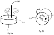
- the rotating shaft 212 is connected to the cam 214 in an off-centre position, that is, the axis x-x illustrated in Figure 3a is the notional central axis of rotation of the cam 214.
- the cam 214 will rotate about the axis of the rotating shaft 212 and in this way the skilled person will see that the cam 214 rotates eccentrically about the axis of the rotating shaft 212 as illustrated in Figure 3b .
- the centre of the rotating shaft 212 and that of the cam 214 are eccentric and not aligned.
- This eccentric alignment of rotating shaft 212 and the cam 214 allows for a reciprocating movement of the piston 216 between a minimum throw T min and maximum throw T max , as illustrated in Figures 4a and 4b .
- the eccentric cam centre X can move in circular path around rotating shaft 212 as the motor 210 rotates the shaft. Therefore, as the cam 214 rotates eccentrically the piston 216 moves between an innermost position (known as bottom dead centre) as shown in Figure 4a , and an outermost position (known as top dead centre) as shown in Figure 4b .
- the first collet housing 206 may optionally include a channel 222 formed therethrough to allow the piston 216 to contact and moveably contact the second collet housing 208.
- Figures 5a and 5b illustrate the relative positions of the first collet 203 with respect to the second collet 202.
- the piston 216 has been omitted.
- the first collet housing 208 is located at a position whereby the pitch P between the between the first and second pick-up openings 204, 205 is a minimum, P min , which corresponds to the minimum throw T min of the piston 216 at the bottom dead centre position of Figure 4a .
- the first collet housing 208 is located at a position whereby the pitch P between the between the first and second pick-up openings 204, 205 is a maximum, P max , which corresponds to the maximum throw T max of the piston 216 at the top dead centre position of Figure 4b .
- the pitch P between the first and second pick-up openings 204, 205 at a minimum, P min , or a maximum P max
- the pitch P may be any position intermediate the maximum pitch P max and minimum pitch P min .
- Figure 6a and Figure 6b illustrate pick and place operations respectively, of, for example semiconductor dies 626, using the transfer head 200 according to embodiments.
- the pitch of the first and second collet openings 204, 205 is moved to a first position, corresponding to the bottom dead centre position as discussed above, using the control arrangement described above, to correspond the pitch of adjacent semiconductor dies 626 arranged on a carrier tape 624.
- the adjacent semiconductor dies 626 are picked up and removed from the carrier tape 624 by a vacuum (e.g. a negative pressure) at the first and second collet openings 204, 205.
- a vacuum e.g. a negative pressure
- the pitch of the first and second collet openings 204, 205 is moved to a second position, corresponding to the top dead centre position as discussed above, using the control arrangement described above, to correspond the pitch of target positions 628 of the semiconductor dies 626.
- the vacuum is then released (e.g. a positive pressure) from the first and second collet openings 204, 205 and the semiconductor dies are placed on the respective target positions 628.
- the target positions 628 may be lead frames for a semiconductor device, a packaging tape or other substrate such as a printed circuit board.
- the collet pitch at the pick up position is less than the collet pitch at the place position
- the collet pitch may be set any appropriate position between the maximum and minimum positions as required by the circumstances.
- the pitch of the semiconductor dies at the pick up position may smaller than the pitch at the target position.
- the pitch of the semiconductor dies at the pick up position may substantially equal to the pitch at the target position.
- FIG. 7 illustrates transfer head 700 for a semiconductor die transfer apparatus comprising two movable collet housings 708-1, 708-2 which are movable with respect to one another and movable with respect to a fixed collet housing 706.
- the transfer head 700 comprises a first collet 702, a second collet 703-1 and a third collet 703-2.
- the first, second and third collets 702, 703-1, 703-2 (also known a vacuum pipets) comprise respective first, second and third pick-up openings 704, 705-1, 705-2 formed at free ends thereof.
- the first collet 702 is fixed to a first collet housing 706 at an end thereof opposite the first collet free end.
- the second collet 703-1 is fixed to a second collet housing 708-1 at an end thereof opposite the second collet free end.
- the third collet 703-2 is fixed to a third collet housing 703-2 at an end thereof opposite the third collet free end.
- the pick-up opening 704 of the first collet 702 is spaced apart from the pick-up opening 705-2 of the third collet 703-2 by a first pitch P 1 .
- the third collet 703-2 is moveable with respect to the first collet 702.
- the first collet housing 706 is fixed and the third collet housing 708-2 is spaced apart from and moveable with respect to the first collet housing 706.
- the pitch P 1 between the first and third pick-up openings 704, 705-2 is variable between a maximum pitch position and a minimum pitch position.
- the pick-up opening 705-1 of the second collet is spaced apart from the pick-up opening 705-2 of the third collet 703-2 by a second pitch P 2 .
- the third collet 703-2 and the second collet are moveable with respect to each other. In this way the second pitch P 2 , between the second and third pick-up openings 705-1, 705-2 is variable between a maximum pitch position and a minimum pitch position.
- the position of the second collet housing 708-1 is moveable with respect to the first collet housing 706 and the third collet housing 708-1 by any suitable control arrangement.
- the third collet housing 708-2 is moveable with respect to the first collet housing 706 and the second collet housing 708-1 by any suitable control arrangement.
- the control arrangements for controlling the position of the second collet housing 708-1 and the third collet housing 708-2 may be similar to those mentioned above with respect to Figures 2 , 3a , 3b , 4a and 4b .
- the movement of the second and third collet housings 708-1, 708-2 may be achieved by way of respective motors 710 each of which may be connected to respective rotating shafts 712.
- the rotating shafts 712 may be connected to respective cams 714, where each cam 714 acts on a respective translatable arm or piston 716 to move the respective pistons 716 horizontally under the rotating action of the respective cam 714.
- the horizontal movement of the piston 716 thus causes the respective second or third collet housing 708-1, 708-2 to move with respect to each other and the first collet housing 706.
- the second and third collet housings 708-2, 708-1 are each moveably connected to the first collet housing 706 by for example leaf springs 720.
- the leaf springs 720 operate as discussed above with respect to Figure 2 , to ensure that the second collet housing 708-1 and the third collet housing 708-2 are each resiliently biased against their pistons 716, thus ensuring contact between respective pistons 716 and moveable collet housings 708-1, 708-2. This further ensures that control of the pitch P 1 and P 2 , between their maximum extent and minimum extent, are based on movements of the respective pistons 716 alone.
- additional springs such as coil springs (not illustrated) may be included to provide an additional resilient return force on the second and third collet housings 708-2, 708-1.
- the arrangement of the rotating shafts 712, cams 714 and pistons 716 follows the arrangement as described above with respect to Figures 3a, 3b , 4a and 4b .
- the diameter of the each of the cams 714 may be equal or different. Where the diameters are equal the respective throws of the pistons 716 will be equal (assuming that the rotating shafts are identically located), however where the diameters are not equal the respective throws of the pistons 716 will be different.
- first collet housing 706 may optionally include a channel 722 formed therethrough.
- third collet housing may optionally include a corresponding channel 722 formed therethrough.
- the channels 722 formed in first collet housing 706 and the third collet housing 708-2 may each be configured and arranged to allow the respective pistons 716 to contact and moveably contact the respective second and third collet housings 708-1, 708-2.
- translatable arms or pistons 216, 716 may form part of, or be driven by a linear motor, such as a piezoelectric motor or Lorentz motor.
- FIG 8 illustrates a chip transfer apparatus 800 comprising a transfer head 200 as described above. Whilst the electronic component transfer apparatus 800 of Figure 8 illustrates a plurality of transfer heads comprising two collets according to Figure 2 , the skilled person will appreciate that the transfer head may comprise two or more collets, such as the type described above with respect to Figure 7 .
- the pitch control as described above allows for different pitches at a source location (i.e. a pick position) and different pitches at the target location (i.e. place position).
- the electronic component transfer apparatus of Figure 8 comprises a plurality of, in this case eight, transfer heads 200 mounted to a rotatable transfer assembly 824.
- the rotatable transfer assembly 824 is adapted to rotate about the axis Y-Y.
- the electronic component transfer apparatus is arranged to pick, for example, semiconductor dies or other electronic component (not illustrated) from a matrix 830 of such semiconductor dies arranged on a carrier film, and place the semiconductor dies at a target location 840, such as a lead frame or a carrier tape.
- the matrix 830 may be considered a source location.
- the transfer head located at position 1 picks semiconductor dies from the carrier film.
- the rotatable transfer assembly 824 is rotated in a step-wise manner in either a clockwise or anticlockwise direction such that the transfer head holding the semiconductor dies is rotated to position through positions 2 to 6 to position 7.
- the transfer head transfers the semiconductor dies to the target location 840.
- the next transfer head is moved sequentially to position 1 and the next pick up operation is completed and this transfer head is moved through positions 2 to 6 to position 7 where the place operation is completed. In this way the skilled person will see that the only position where no semiconductor dies are held by the transfer head is at position 8.
- optical inspection systems may be placed at various positions.
- a semiconductor die inspection system may be arranged to view the picked dies at position 3.
- a further inspection system may be positioned to inspect s place operation to ensure that the semiconductor dies have been correctly placed at the target location 830.
- semiconductor dies on the carrier film may fixed to an indexer allowing the carrier film to be moved or indexed vertically V and/or horizontally H (as shown in Figure 8 ) to allow adjacent semiconductor dies to be removed from the carrier film.
Landscapes
- Engineering & Computer Science (AREA)
- Mechanical Engineering (AREA)
- Container, Conveyance, Adherence, Positioning, Of Wafer (AREA)
Abstract
This disclosure relates to: a transfer head for an electronic component transfer apparatus, the transfer head comprising: a first vacuum pipet laterally spaced from a second vacuum pipet with a first pitch therebetween; wherein the first pitch is variable between a first pitch position and a second pitch position. The disclosure also relates to a method of transferring an electronic component from a source location to a target location.
Description
- The present disclosure relates to a transfer head for an electronic component transfer apparatus. This disclosure also relates to an electronic component transfer apparatus and associated method of operation.
- Electronic components such as semiconductor dies, also referred to as "chips", are typically manufactured by front-end epitaxial processes on a planar substrate known as a wafer, whereby the dies are arranged in a matrix on the substrate having a plurality of rows and columns of dies. After manufacture, a surface of wafer may typically be fixed to a carrier film or tape to support the individual dies following singulation of the dies. During singulation, the dies are physically separated from each other by a series of horizontal and vertical cuts through the wafer from one surface without cutting through the carrier film. In this way a matrix of individual semiconductor dies supported by the carrier film is obtained.
- In known die handling processes, each die is mechanically picked up from the carrier film by moving the carrier film with respect to a mechanical pick-up. The mechanical pick-up is also known as a transfer head. The mechanical pick-up is then rotated and/or translated to allow the die to be placed at a target location such as a lead frame or other suitable substrate. This process is then repeated for each die on the carrier film until all of the dies on the carrier film are removed.
- A known mechanical pick-up or
transfer head 100, for an electronic component transfer apparatus is shown inFigure 1 . The knowntransfer head 100 comprises a vacuum pipet (also known as a collet) 102 for picking up the semiconductor die from the carrier film, holding the semiconductor die whilst the transfer head is moved to a target position, and releasing the semiconductor die from thecollet 102 to a target location. Thecollet 102 comprises a pick-up opening 104 whereby a variable pressure generated at the opening 104. For example, a negative pressure at the pick-up opening 104 pulls the semiconductor die from the carrier film and holds the semiconductor die thereto (known as a "pick" operation). - The
transfer head 100 is fixed to atransfer head housing 106, and the transfer head housing is fixedly attachable to a moveable member (not illustrated), such as a rotatable member. The transfer head is then moved, for example by rotation, to a target position, and the semiconductor die is released from thecollet 102 and placed at a target position, such as a lead frame, by a positive pressure at the pick-up opening 104 (known as a "place" operation). Two ormore transfer heads 100 may be radially spaced on a rotating member (not illustrated) or linearly spaced a translating member (not illustrated), such that when afirst transfer head 100 is performing a pick operation, asecond transfer head 100 is performing a place operation. Increasing the number oftransfer heads 100 may increase the through-put (that is number of dies processed per hour) is limited. However where optical inspection systems are used to monitor pick and place operations, the number oftransfer heads 100 spaced on a rotating member is limited because a spacing is required between the transfer heads to allow a viewing window between the transfer heads. - Currently, the through-put is limited. The acceleration, speed of rotation or translation and deceleration of the transfer heads during the movement from the pick-up position to the target position are at or near maximum, taking into account current drive motors and the mechanical loads to be imposed on the various components. As a result, a further increase in the performance of the known transferring apparatus is difficult without improvements to the drive motors.
- Various example embodiments are directed to issues such as those addressed above and/or others which may become apparent from the following disclosure concerning increasing the throughput of semiconductor die handling systems.
- In certain example embodiments, aspects of the present disclosure involve increasing the throughput of semiconductor die handling systems without increasing the speed of rotation and/or number of transfer heads.
- According to an embodiment there is provided a transfer head for an electronic component transfer apparatus, the transfer head comprising: a first vacuum pipet laterally spaced from a second vacuum pipet with a first pitch therebetween; wherein the first pitch is variable between a first pitch position and a second pitch position.
- The first vacuum pipet may be fixed; and the second vacuum pipet is moveable in a lateral direction with respect to the first vacuum pipet to vary the first pitch.
- Optionally, a third vacuum pipet laterally spaced from the first vacuum pipet and the second vacuum pipet with a second pitch between the second vacuum pipet and the third vacuum pipet; wherein the second pitch is variable between a first pitch position and a second pitch position.
- The third vacuum pipet may be moveable in a lateral direction with respect to the second vacuum pipet to vary the second pitch.
- The third vacuum pipet may be moveable in a lateral direction with respect to the first vacuum pipet.
- The first, second and third vacuum pipets may be mounted on respective first, second and third housings.
- The transfer head according to embodiments may further comprise one or more pitch controllers, configured and arranged to vary the first pitch and/or the second pitch. The pitch controller may comprise a piston configured and arranged to move the second vacuum pipet with respect to the first vacuum pipet.
- Optionally, the pitch controller may further comprise: a motor rotatably attached to an eccentrically rotatable cam, wherein the rotatable cam is configured and arranged to move the piston under the rotating action of the cam.
- Optionally, the pitch controller may comprise a linear motor configured and arranged to move the piston. The linear motor may be a piezoelectric motor or a Lorentz motor.
- There is also provided a method of transferring an electronic component from a source location to a target location the method comprising: providing a transfer head comprising: a first vacuum pipet laterally spaced from a second vacuum pipet with a first pitch therebetween; wherein the first pitch is variable between a first pitch position and a second pitch position; positioning the transfer head at a source location; adjusting the first pitch between the first vacuum pipet and second vacuum pipet to correspond to the pitch between first and second electronic components on the source location; picking the first and second electronic components from the source location; moving the transfer head to a target location; adjusting the first pitch between the first vacuum pipet and second vacuum pipet to correspond to the pitch between first and second positions at a target location; and placing the first and second electronic components at the target locations.
- There is further provided an electronic component transfer apparatus of comprising a plurality of transfer heads according to embodiments. The plurality of transfer heads may be radially spaced on a rotating assembly.
- So that the manner in which the features of the present disclosure can be understood in detail, a more particular description is made with reference to embodiments, some of which are illustrated in the appended figures. It is to be noted, however, that the appended figures illustrate only typical embodiments and are therefore not to be considered limiting of its scope. The figures are for facilitating an understanding of the disclosure and thus are not necessarily drawn to scale. Advantages of the subject matter claimed will become apparent to those skilled in the art upon reading this description in conjunction with the accompanying figures, in which like reference numerals have been used to designate like elements, and in which:
-
Figure 1 shows a known transfer head for a semiconductor die transfer apparatus; -
Figure 2 illustrates a transfer head for a semiconductor die transfer apparatus according to an embodiment; -
Figure 3a illustrates a perspective view of a cam arrangement according to an embodiment; -
Figure 3b illustrates a top down view of a cam, arrangement according to an embodiment, in a first position and a second position; -
Figure 4a illustrates a top down view of a cam, arrangement according to an embodiment, in a bottom dead centre position; -
Figure 4b illustrates a top down view of a cam, arrangement according to an embodiment, in a top dead centre position; -
Figures 5a illustrates a first collet head located in first position with respect to a second collet head; -
Figures 5b illustrates a first collet head located in second position with respect to a second collet head; -
Figure 6a illustrates a pick operation whereby a first collet head is located in first position with respect to a second collet head; -
Figure 6b illustrates a place operation whereby a first collet head is located in second position with respect to a second collet head; -
Figure 7 illustrates a transfer head for a semiconductor die transfer apparatus according to an embodiment; and -
Figure 8 illustrates a transfer apparatus comprising a plurality of transfer heads according to embodiments. -
Figure 2 illustrates atransfer head 200 for a semiconductor die transfer apparatus according to embodiments. Thetransfer head 200 comprises afirst collet 202 and asecond collet 203. The first andsecond collets 202, 203 (also known as vacuum pipets) comprise respective first andsecond openings first collet 202 is mounted to afirst collet housing 206 at an end thereof opposite the first collet free end. Thesecond collet 203 is mounted to asecond collet housing 208 at an end thereof opposite the second collet free end. - The pick-up opening 204 of the
first collet 202 is spaced apart from the pick-up opening 205 of thesecond collet 203 by a pitch P. Thesecond collet 203 is moveable with respect to thefirst collet 202. Likewise, thefirst collet housing 206 is fixed and thesecond collet housing 208 is spaced apart and moveable with respect to thefirst collet housing 206. In this way the pitch P, between the first and second pick-upopenings - The position of the
second collet housing 208 is moveable with respect to the first collet housing by any suitable pitch control arrangement. For example, movement may be achieved by way of amotor 210 which is connected to and rotates arotating shaft 212. Therotating shaft 212 may be connected to acam 214, where thecam 214 acts on a translatable arm orpiston 216 to move the piston horizontally under the rotating action of thecam 214. The horizontal movement of thepiston 216 thus causes thesecond collet housing 208 to move with respect to thefirst collet housing 206. Thesecond collet housing 208 is moveably connected to thefirst collet housing 206 by for example a leaf springs 220. The leaf springs 220 operate to guide thesecond collet housing 208 and as return mechanism to ensure that thesecond collet housing 208 is resiliently biased against thepiston 216, thus ensuring contact betweenpiston 216 and thesecond collet housing 208 at all times. This further ensures that control of the pitch P, between a maximum extent and a minimum extent, is based on movement of thepiston 216 alone. Optionally, additional springs such as coil springs (not illustrated) may be included to provide an additional resilient return force on thesecond collet housing 208. - Referring again to the
rotating shaft 212, and thecam 214, the specific details of this arrangement are illustrated inFigures 3a and 3b . As illustrated, therotating shaft 212 is connected to thecam 214 in an off-centre position, that is, the axis x-x illustrated inFigure 3a is the notional central axis of rotation of thecam 214. However, given that therotating shaft 212 is connected off centre, thecam 214 will rotate about the axis of therotating shaft 212 and in this way the skilled person will see that thecam 214 rotates eccentrically about the axis of therotating shaft 212 as illustrated inFigure 3b . In other words, the centre of therotating shaft 212 and that of thecam 214 are eccentric and not aligned. - This eccentric alignment of
rotating shaft 212 and thecam 214, allows for a reciprocating movement of thepiston 216 between a minimum throw Tmin and maximum throw Tmax, as illustrated inFigures 4a and 4b . In this case, the eccentric cam centre X can move in circular path around rotatingshaft 212 as themotor 210 rotates the shaft. Therefore, as thecam 214 rotates eccentrically thepiston 216 moves between an innermost position (known as bottom dead centre) as shown inFigure 4a , and an outermost position (known as top dead centre) as shown inFigure 4b . - Referring again to
Figure 2 , and as described above, the reciprocating movement of thepiston 216 acting on thesecond collet housing 208 moves thesecond collet 203 with respect to thefirst collet 202. Thefirst collet housing 206 may optionally include achannel 222 formed therethrough to allow thepiston 216 to contact and moveably contact thesecond collet housing 208. -
Figures 5a and 5b illustrate the relative positions of thefirst collet 203 with respect to thesecond collet 202. For brevity and ease of understanding thepiston 216 has been omitted. InFigure 5a thefirst collet housing 208 is located at a position whereby the pitch P between the between the first and second pick-upopenings piston 216 at the bottom dead centre position ofFigure 4a . InFigure 5b thefirst collet housing 208 is located at a position whereby the pitch P between the between the first and second pick-upopenings piston 216 at the top dead centre position ofFigure 4b . - Whilst the above discussion and figures shows that the pitch P between the first and second pick-up
openings -
Figure 6a and Figure 6b illustrate pick and place operations respectively, of, for example semiconductor dies 626, using thetransfer head 200 according to embodiments. As shown inFigure 6a the pitch of the first andsecond collet openings carrier tape 624. The adjacent semiconductor dies 626 are picked up and removed from thecarrier tape 624 by a vacuum (e.g. a negative pressure) at the first andsecond collet openings - As shown in
Figure 6b , the pitch of the first andsecond collet openings target positions 628 of the semiconductor dies 626. The vacuum is then released (e.g. a positive pressure) from the first andsecond collet openings - Whilst the above discussion illustrates that the collet pitch at the pick up position is less than the collet pitch at the place position, the skilled person that will appreciate that the collet pitch may be set any appropriate position between the maximum and minimum positions as required by the circumstances. For example the pitch of the semiconductor dies at the pick up position may smaller than the pitch at the target position. Likewise, the pitch of the semiconductor dies at the pick up position may substantially equal to the pitch at the target position.
- Whilst the above discussed
transfer head 200 for a semiconductor die transfer apparatus relates two collets, one fixed and the other movable, the skilled person will appreciate that two or more moveable collets may be implemented based on the above teaching.Figure 7 illustratestransfer head 700 for a semiconductor die transfer apparatus comprising two movable collet housings 708-1, 708-2 which are movable with respect to one another and movable with respect to a fixedcollet housing 706. Thetransfer head 700 comprises afirst collet 702, a second collet 703-1 and a third collet 703-2. The first, second andthird collets 702, 703-1, 703-2 (also known a vacuum pipets) comprise respective first, second and third pick-upopenings 704, 705-1, 705-2 formed at free ends thereof. Thefirst collet 702 is fixed to afirst collet housing 706 at an end thereof opposite the first collet free end. The second collet 703-1 is fixed to a second collet housing 708-1 at an end thereof opposite the second collet free end. The third collet 703-2 is fixed to a third collet housing 703-2 at an end thereof opposite the third collet free end. - The pick-up
opening 704 of thefirst collet 702 is spaced apart from the pick-up opening 705-2 of the third collet 703-2 by a first pitch P1. The third collet 703-2 is moveable with respect to thefirst collet 702. Likewise, thefirst collet housing 706 is fixed and the third collet housing 708-2 is spaced apart from and moveable with respect to thefirst collet housing 706. In this way the pitch P1, between the first and third pick-upopenings 704, 705-2 is variable between a maximum pitch position and a minimum pitch position. Furthermore, the pick-up opening 705-1 of the second collet is spaced apart from the pick-up opening 705-2 of the third collet 703-2 by a second pitch P2. The third collet 703-2 and the second collet are moveable with respect to each other. In this way the second pitch P2, between the second and third pick-up openings 705-1, 705-2 is variable between a maximum pitch position and a minimum pitch position. - The position of the second collet housing 708-1 is moveable with respect to the
first collet housing 706 and the third collet housing 708-1 by any suitable control arrangement. Likewise, the third collet housing 708-2 is moveable with respect to thefirst collet housing 706 and the second collet housing 708-1 by any suitable control arrangement. The control arrangements for controlling the position of the second collet housing 708-1 and the third collet housing 708-2 may be similar to those mentioned above with respect toFigures 2 ,3a ,3b ,4a and 4b . For example, the movement of the second and third collet housings 708-1, 708-2 may be achieved by way ofrespective motors 710 each of which may be connected to respectiverotating shafts 712. The rotatingshafts 712 may be connected torespective cams 714, where eachcam 714 acts on a respective translatable arm orpiston 716 to move therespective pistons 716 horizontally under the rotating action of therespective cam 714. The horizontal movement of thepiston 716 thus causes the respective second or third collet housing 708-1, 708-2 to move with respect to each other and thefirst collet housing 706. The second and third collet housings 708-2, 708-1 are each moveably connected to thefirst collet housing 706 by for example leaf springs 720. The leaf springs 720 operate as discussed above with respect toFigure 2 , to ensure that the second collet housing 708-1 and the third collet housing 708-2 are each resiliently biased against theirpistons 716, thus ensuring contact betweenrespective pistons 716 and moveable collet housings 708-1, 708-2. This further ensures that control of the pitch P1 and P2, between their maximum extent and minimum extent, are based on movements of therespective pistons 716 alone. Optionally, additional springs such as coil springs (not illustrated) may be included to provide an additional resilient return force on the second and third collet housings 708-2, 708-1. - The arrangement of the
rotating shafts 712,cams 714 andpistons 716 follows the arrangement as described above with respect toFigures 3a, 3b ,4a and 4b . In the case of the arrangement ofFigure 7 , the diameter of the each of thecams 714 may be equal or different. Where the diameters are equal the respective throws of thepistons 716 will be equal (assuming that the rotating shafts are identically located), however where the diameters are not equal the respective throws of thepistons 716 will be different. - The reciprocating movement of the
pistons 716 acting on the respective second and third collet housings 708-1, 708-2 move the second and third collets 703-1, 703-2 with respect to each other and with respect to thefirst collet 702. As with the arrangement ofFigure 2 , thefirst collet housing 706 may optionally include achannel 722 formed therethrough. Likewise, the third collet housing may optionally include acorresponding channel 722 formed therethrough. Thechannels 722 formed infirst collet housing 706 and the third collet housing 708-2 may each be configured and arranged to allow therespective pistons 716 to contact and moveably contact the respective second and third collet housings 708-1, 708-2. - Whilst the above discussion relates to the use of
motors shafts cams pistons - The skilled person will appreciate that one or more transfer heads 200, 700 according to embodiments may form part of an electronic component transfer apparatus.
Figure 8 illustrates achip transfer apparatus 800 comprising atransfer head 200 as described above. Whilst the electroniccomponent transfer apparatus 800 ofFigure 8 illustrates a plurality of transfer heads comprising two collets according toFigure 2 , the skilled person will appreciate that the transfer head may comprise two or more collets, such as the type described above with respect toFigure 7 . The pitch control as described above allows for different pitches at a source location (i.e. a pick position) and different pitches at the target location (i.e. place position). - The electronic component transfer apparatus of
Figure 8 , comprises a plurality of, in this case eight, transfer heads 200 mounted to arotatable transfer assembly 824. Therotatable transfer assembly 824 is adapted to rotate about the axis Y-Y. To aid understanding the positions of the transfer heads have been numbered 1 to 8. The electronic component transfer apparatus is arranged to pick, for example, semiconductor dies or other electronic component (not illustrated) from amatrix 830 of such semiconductor dies arranged on a carrier film, and place the semiconductor dies at atarget location 840, such as a lead frame or a carrier tape. In this respect thematrix 830 may be considered a source location. - The transfer head located at
position 1 picks semiconductor dies from the carrier film. Therotatable transfer assembly 824 is rotated in a step-wise manner in either a clockwise or anticlockwise direction such that the transfer head holding the semiconductor dies is rotated to position through positions 2 to 6 toposition 7. Atposition 7 the transfer head transfers the semiconductor dies to thetarget location 840. As the transfer head holding the semiconductor dies is moved fromposition 1, the next transfer head is moved sequentially toposition 1 and the next pick up operation is completed and this transfer head is moved through positions 2 to 6 toposition 7 where the place operation is completed. In this way the skilled person will see that the only position where no semiconductor dies are held by the transfer head is atposition 8. - Whilst not illustrated, the skilled person will appreciate that optical inspection systems may be placed at various positions. For example a semiconductor die inspection system may be arranged to view the picked dies at position 3. In addition a further inspection system may be positioned to inspect s place operation to ensure that the semiconductor dies have been correctly placed at the
target location 830. Also, whilst not illustrated semiconductor dies on the carrier film may fixed to an indexer allowing the carrier film to be moved or indexed vertically V and/or horizontally H (as shown inFigure 8 ) to allow adjacent semiconductor dies to be removed from the carrier film. - Particular and preferred aspects of the invention are set out in the accompanying independent claims. Combinations of features from the dependent and/or independent claims may be combined as appropriate and not merely as set out in the claims.
- The scope of the present disclosure includes any novel feature or combination of features disclosed therein either explicitly or implicitly or any generalisation thereof irrespective of whether or not it relates to the claimed invention or mitigate against any or all of the problems addressed by the present invention. The applicant hereby gives notice that new claims may be formulated to such features during prosecution of this application or of any such further application derived therefrom. In particular, with reference to the appended claims, features from dependent claims may be combined with those of the independent claims and features from respective independent claims may be combined in any appropriate manner and not merely in specific combinations enumerated in the claims.
- Features which are described in the context of separate embodiments may also be provided in combination in a single embodiment. Conversely, various features which are, for brevity, described in the context of a single embodiment, may also be provided separately or in any suitable sub combination.
- Term "comprising" does not exclude other elements or steps, the term "a" or "an" does not exclude a plurality. Reference signs in the claims shall not be construed as limiting the scope of the claims.
Claims (14)
- A transfer head for an electronic component transfer apparatus, the transfer head comprising: a first vacuum pipet laterally spaced from a second vacuum pipet with a first pitch therebetween; wherein the first pitch is variable between a first pitch position and a second pitch position.
- The transfer head of claim 1, wherein the first vacuum pipet is fixed; and the second vacuum pipet is moveable in a lateral direction with respect to the first vacuum pipet to vary the first pitch.
- The transfer head of claims 1 or 2, further comprising a third vacuum pipet laterally spaced from the first vacuum pipet and the second vacuum pipet with a second pitch between the second vacuum pipet and the third vacuum pipet; wherein the second pitch is variable between a first pitch position and a second pitch position.
- The transfer head of claim 3, wherein the third vacuum pipet is moveable in a lateral direction with respect to the second vacuum pipet to vary the second pitch.
- The transfer head of claim 3 or claim 4, wherein the third vacuum pipet is moveable in a lateral direction with respect to the first vacuum pipet.
- The transfer head of any preceding claim, wherein the first, second and third vacuum pipets are mounted on respective first, second and third housings.
- The transfer head of any preceding claim further comprising one or more pitch controllers, configured and arranged to vary the first pitch and/or the second pitch.
- The transfer head of claim 7, wherein the pitch controller comprises; a piston configured and arranged to move the second vacuum pipet with respect to the first vacuum pipet.
- The transfer head of claims 7 and 8, wherein the pitch controller further comprises: a motor rotatably attached to an eccentrically rotatable cam, wherein the rotatable cam is configured and arranged to move the piston under the rotating action of the cam.
- The transfer head of claim 8, wherein the pitch controller further comprises a linear motor configured and arranged to move the piston.
- The transfer head of claim 10, wherein the linear motor is a piezoelectric motor or a Lorentz motor.
- A method of transferring an electronic component from a source location to a target location the method comprising:providing a transfer head comprising: a first vacuum pipet laterally spaced from a second vacuum pipet with a first pitch therebetween; wherein the first pitch is variable between a first pitch position and a second pitch position;positioning the transfer head at a source location;adjusting the first pitch between the first vacuum pipet and second vacuum pipet to correspond to the pitch between first and second electronic components on the source location;picking the first and second electronic components from the source location;moving the transfer head to a target location;adjusting the first pitch between the first vacuum pipet and second vacuum pipet to correspond to the pitch between first and second positions at a target location; andplacing the first and second electronic components at the target locations.
- An electronic component transfer apparatus of comprising a plurality of transfer heads according to any preceding claim.
- The electronic component transfer apparatus of claim 13, wherein the plurality of transfer heads are radially spaced on a rotating assembly.
Priority Applications (2)
| Application Number | Priority Date | Filing Date | Title |
|---|---|---|---|
| EP19172481.4A EP3734649A1 (en) | 2019-05-03 | 2019-05-03 | Electronic component transfer apparatus |
| US16/864,809 US11594433B2 (en) | 2019-05-03 | 2020-05-01 | Electronic component transfer apparatus |
Applications Claiming Priority (1)
| Application Number | Priority Date | Filing Date | Title |
|---|---|---|---|
| EP19172481.4A EP3734649A1 (en) | 2019-05-03 | 2019-05-03 | Electronic component transfer apparatus |
Publications (1)
| Publication Number | Publication Date |
|---|---|
| EP3734649A1 true EP3734649A1 (en) | 2020-11-04 |
Family
ID=66429197
Family Applications (1)
| Application Number | Title | Priority Date | Filing Date |
|---|---|---|---|
| EP19172481.4A Withdrawn EP3734649A1 (en) | 2019-05-03 | 2019-05-03 | Electronic component transfer apparatus |
Country Status (2)
| Country | Link |
|---|---|
| US (1) | US11594433B2 (en) |
| EP (1) | EP3734649A1 (en) |
Families Citing this family (1)
| Publication number | Priority date | Publication date | Assignee | Title |
|---|---|---|---|---|
| WO2026077611A1 (en) * | 2024-10-10 | 2026-04-16 | Asml Netherlands B.V. | Stage for die placement |
Citations (3)
| Publication number | Priority date | Publication date | Assignee | Title |
|---|---|---|---|---|
| JPS62273749A (en) * | 1986-05-21 | 1987-11-27 | Mitsubishi Electric Corp | Semiconductor chip transfer apparatus |
| JP2003007731A (en) * | 2001-06-27 | 2003-01-10 | Rohm Co Ltd | Method and apparatus for mounting semiconductor chip |
| EP1588402A1 (en) * | 2003-01-16 | 2005-10-26 | Koninklijke Philips Electronics N.V. | Chip transfer method and apparatus |
Family Cites Families (3)
| Publication number | Priority date | Publication date | Assignee | Title |
|---|---|---|---|---|
| US2335613A (en) * | 1942-08-12 | 1943-11-30 | Sayen Emery | Multistation transfer equipment |
| KR970007078Y1 (en) * | 1994-06-03 | 1997-07-15 | Lg Semicon Co Ltd | Devices feeding apparatus |
| US6439631B1 (en) * | 2000-03-03 | 2002-08-27 | Micron Technology, Inc. | Variable-pitch pick and place device |
-
2019
- 2019-05-03 EP EP19172481.4A patent/EP3734649A1/en not_active Withdrawn
-
2020
- 2020-05-01 US US16/864,809 patent/US11594433B2/en active Active
Patent Citations (3)
| Publication number | Priority date | Publication date | Assignee | Title |
|---|---|---|---|---|
| JPS62273749A (en) * | 1986-05-21 | 1987-11-27 | Mitsubishi Electric Corp | Semiconductor chip transfer apparatus |
| JP2003007731A (en) * | 2001-06-27 | 2003-01-10 | Rohm Co Ltd | Method and apparatus for mounting semiconductor chip |
| EP1588402A1 (en) * | 2003-01-16 | 2005-10-26 | Koninklijke Philips Electronics N.V. | Chip transfer method and apparatus |
Also Published As
| Publication number | Publication date |
|---|---|
| US20200350190A1 (en) | 2020-11-05 |
| US11594433B2 (en) | 2023-02-28 |
Similar Documents
| Publication | Publication Date | Title |
|---|---|---|
| CN112201607B (en) | A wafer centering mechanism, wafer transfer device and wafer thinning equipment | |
| JP2930870B2 (en) | Electronic component surface mounting equipment | |
| CN107452666B (en) | Ejector pin assembly and bare core ejector with the ejector pin assembly | |
| EP1620889B1 (en) | Method and apparatus for the multiplexed acquisition of a bare die from a wafer | |
| EP1588402B1 (en) | Chip transfer method and apparatus | |
| US8281483B2 (en) | Fixture for aligning an electronic component | |
| US20110248738A1 (en) | Testing apparatus for electronic devices | |
| CN103972138B (en) | For picking up, the device of semiconductor element is placed and oppressed | |
| JP6217958B2 (en) | Semiconductor chip mounting equipment | |
| CN107492510A (en) | The manufacture method of semiconductor- fabricating device and semiconductor devices | |
| EP0092292B1 (en) | Method of and device for placing chip-type electrical and/or electronic components on a substrate | |
| JP7550945B2 (en) | Apparatus and system | |
| KR20190017181A (en) | Led chips sorting apparatus | |
| US11594433B2 (en) | Electronic component transfer apparatus | |
| EP3417479B1 (en) | Apparatus and method for manufacturing plurality of electronic circuits | |
| US5799858A (en) | Die bonding device | |
| US10481201B2 (en) | Multi-turret handler | |
| CN113307025B (en) | Material part picking device based on COB automatic assembly | |
| CN108028205B (en) | Die placement head with turntable | |
| US20230271333A1 (en) | Apparatus, system and method for a floating end effector module | |
| US20040026938A1 (en) | Apparatus for removing ICS from a wafer | |
| EP4258327B1 (en) | An apparatus for transferring semiconductor circuits | |
| KR102521081B1 (en) | Gripper for gripping a substrate and apparatus including the same | |
| WO2017111349A1 (en) | Flip chip mounting device | |
| KR20040100030A (en) | Apparatus for transfer a semiconductor substrate and apparatus for manufacturing a semiconductor substrate having the same |
Legal Events
| Date | Code | Title | Description |
|---|---|---|---|
| PUAI | Public reference made under article 153(3) epc to a published international application that has entered the european phase |
Free format text: ORIGINAL CODE: 0009012 |
|
| STAA | Information on the status of an ep patent application or granted ep patent |
Free format text: STATUS: THE APPLICATION HAS BEEN PUBLISHED |
|
| AK | Designated contracting states |
Kind code of ref document: A1 Designated state(s): AL AT BE BG CH CY CZ DE DK EE ES FI FR GB GR HR HU IE IS IT LI LT LU LV MC MK MT NL NO PL PT RO RS SE SI SK SM TR |
|
| AX | Request for extension of the european patent |
Extension state: BA ME |
|
| STAA | Information on the status of an ep patent application or granted ep patent |
Free format text: STATUS: THE APPLICATION IS DEEMED TO BE WITHDRAWN |
|
| 18D | Application deemed to be withdrawn |
Effective date: 20210505 |