EP3734572A1 - Movement information calculation device, movement information calculation method, and movement information calculation program - Google Patents
Movement information calculation device, movement information calculation method, and movement information calculation program Download PDFInfo
- Publication number
- EP3734572A1 EP3734572A1 EP18883868.4A EP18883868A EP3734572A1 EP 3734572 A1 EP3734572 A1 EP 3734572A1 EP 18883868 A EP18883868 A EP 18883868A EP 3734572 A1 EP3734572 A1 EP 3734572A1
- Authority
- EP
- European Patent Office
- Prior art keywords
- center
- gravity
- movable body
- velocity
- turning
- Prior art date
- Legal status (The legal status is an assumption and is not a legal conclusion. Google has not performed a legal analysis and makes no representation as to the accuracy of the status listed.)
- Withdrawn
Links
Images



Classifications
-
- G—PHYSICS
- G01—MEASURING; TESTING
- G01C—MEASURING DISTANCES, LEVELS OR BEARINGS; SURVEYING; NAVIGATION; GYROSCOPIC INSTRUMENTS; PHOTOGRAMMETRY OR VIDEOGRAMMETRY
- G01C21/00—Navigation; Navigational instruments not provided for in groups G01C1/00 - G01C19/00
- G01C21/10—Navigation; Navigational instruments not provided for in groups G01C1/00 - G01C19/00 by using measurements of speed or acceleration
- G01C21/12—Navigation; Navigational instruments not provided for in groups G01C1/00 - G01C19/00 by using measurements of speed or acceleration executed aboard the object being navigated; Dead reckoning
- G01C21/16—Navigation; Navigational instruments not provided for in groups G01C1/00 - G01C19/00 by using measurements of speed or acceleration executed aboard the object being navigated; Dead reckoning by integrating acceleration or speed, i.e. inertial navigation
- G01C21/18—Stabilised platforms, e.g. by gyroscope
-
- G—PHYSICS
- G01—MEASURING; TESTING
- G01C—MEASURING DISTANCES, LEVELS OR BEARINGS; SURVEYING; NAVIGATION; GYROSCOPIC INSTRUMENTS; PHOTOGRAMMETRY OR VIDEOGRAMMETRY
- G01C21/00—Navigation; Navigational instruments not provided for in groups G01C1/00 - G01C19/00
- G01C21/20—Instruments for performing navigational calculations
- G01C21/203—Instruments for performing navigational calculations specially adapted for water-borne vessels
-
- G—PHYSICS
- G01—MEASURING; TESTING
- G01C—MEASURING DISTANCES, LEVELS OR BEARINGS; SURVEYING; NAVIGATION; GYROSCOPIC INSTRUMENTS; PHOTOGRAMMETRY OR VIDEOGRAMMETRY
- G01C21/00—Navigation; Navigational instruments not provided for in groups G01C1/00 - G01C19/00
- G01C21/10—Navigation; Navigational instruments not provided for in groups G01C1/00 - G01C19/00 by using measurements of speed or acceleration
-
- G—PHYSICS
- G01—MEASURING; TESTING
- G01C—MEASURING DISTANCES, LEVELS OR BEARINGS; SURVEYING; NAVIGATION; GYROSCOPIC INSTRUMENTS; PHOTOGRAMMETRY OR VIDEOGRAMMETRY
- G01C21/00—Navigation; Navigational instruments not provided for in groups G01C1/00 - G01C19/00
- G01C21/10—Navigation; Navigational instruments not provided for in groups G01C1/00 - G01C19/00 by using measurements of speed or acceleration
- G01C21/12—Navigation; Navigational instruments not provided for in groups G01C1/00 - G01C19/00 by using measurements of speed or acceleration executed aboard the object being navigated; Dead reckoning
- G01C21/16—Navigation; Navigational instruments not provided for in groups G01C1/00 - G01C19/00 by using measurements of speed or acceleration executed aboard the object being navigated; Dead reckoning by integrating acceleration or speed, i.e. inertial navigation
-
- G—PHYSICS
- G01—MEASURING; TESTING
- G01M—TESTING STATIC OR DYNAMIC BALANCE OF MACHINES OR STRUCTURES; TESTING OF STRUCTURES OR APPARATUS, NOT OTHERWISE PROVIDED FOR
- G01M1/00—Testing static or dynamic balance of machines or structures
- G01M1/12—Static balancing; Determining position of centre of gravity
- G01M1/122—Determining position of centre of gravity
-
- G—PHYSICS
- G05—CONTROLLING; REGULATING
- G05D—SYSTEMS FOR CONTROLLING OR REGULATING NON-ELECTRIC VARIABLES
- G05D1/00—Control of position, course, altitude or attitude of land, water, air or space vehicles, e.g. using automatic pilots
- G05D1/02—Control of position or course in two dimensions
- G05D1/0206—Control of position or course in two dimensions specially adapted to water vehicles
-
- G—PHYSICS
- G08—SIGNALLING
- G08G—TRAFFIC CONTROL SYSTEMS
- G08G3/00—Traffic control systems for marine craft
- G08G3/02—Anti-collision systems
-
- B—PERFORMING OPERATIONS; TRANSPORTING
- B63—SHIPS OR OTHER WATERBORNE VESSELS; RELATED EQUIPMENT
- B63B—SHIPS OR OTHER WATERBORNE VESSELS; EQUIPMENT FOR SHIPPING
- B63B49/00—Arrangements of nautical instruments or navigational aids
Definitions
- the present disclosure relates to a movement information calculating device, a movement information calculating method, and a movement information calculating program which calculate movement information of a movable body such as a ship, particularly, information related to turning of the movable body.
- a display apparatus of Patent Document 1 measures a velocity, a direction, and a turning angular velocity of a movable body so as to calculate a movement track in the past and an estimated track in the future.
- the display apparatus of Patent Document 1 displays both of the movement path in the past and the estimated path in the future.
- Patent Document 1 WO1993/007448A1
- the information acquired by the devices contrived in the past may be insufficient as estimation data during turning. Therefore, further data indicating a state of the movable body during turning is demanded.
- a purpose of the present disclosure is to further fulfill data which indicates a state of a movable body during turning.
- a movement information calculating device includes a position calculator configured to calculate a position of a movable body, a velocity calculator configured to calculate a velocity of the movable body, an attitude calculator configured to calculate an attitude of the movable body, a center-of-gravity information calculating module, and a turning information calculating module.
- the center-of-gravity information calculating module calculates a center-of-gravity position and a center-of-gravity velocity of the movable body by using the position, the velocity, and the attitude.
- the turning information calculating module calculates one of a turning center position and a pivoting position of the movable body by using the center-of-gravity position and the center-of-gravity velocity.
- the turning center position or the pivoting position which indicates the state of the movable body during turning can be calculated by using the position, the velocity, and the attitude of the movable body.
- data which indicates the state of the movable body during turning can further be fulfilled.
- FIG. 1 is a functional block diagram of the movement information calculating device according to Embodiment 1 of the present disclosure.
- Fig. 2 is a plan view illustrating a turning state of a ship. Note that, although a ship is used as a movable body in this embodiment, various moving bodies, such as another water-surface movable body, an underwater movable body, and an aerial movable body are applicable. Configurations of the present disclosure are especially effective for a movable body with a large body such as a hull and a fuselage.
- the movement information calculating device 10 includes a position calculator 20, a velocity calculator 30, an attitude calculator 40, a center-of-gravity information calculating module 50, and a turning information calculating module 60.
- the position calculator 20 is implemented by a positioning sensor
- the velocity calculator 30 is implemented by a velocity sensor
- the attitude calculator 40 is implemented by an attitude sensor.
- the center-of-gravity information calculating module 50 and the turning information calculating module 60 are implemented by, for example, a storage device which stores a program for executing these functions, and computing elements (e.g., a CPU) which execute the program stored in the storage device.
- the positioning sensor corresponds to the "position calculator”
- the velocity sensor corresponds to the "velocity calculator”
- the attitude sensor corresponds to the "attitude calculator” of the present disclosure.
- the movement information calculating device 10 is connected to a display unit 70. Note that this display unit 70 may be included in the movement information calculating device 10.
- the movement information calculating device 10 and the display unit 70 are equipped in a hull 100 as illustrated in Fig. 2 .
- the hull 100 is provided with compound sensors 101, 102, and 103.
- the compound sensors 101 and 102 are disposed around the stern of the hull 100.
- the compound sensors 101 and 102 are disposed at different positions from each other in a Yb-direction in a Body coordinate system (a movable body coordinate system).
- the compound sensor 103 is disposed around the bow of the hull 100.
- the compound sensor 103 is disposed at a different position from the compound sensors 101 and 102 in a direction connecting the bow and the stern of the hull 100, that is, in an Xb-direction in the Body coordinate system.
- the arrangement of the compound sensors 101, 102, and 103 is not limited to this, and the number of compound sensors provided to the hull 100 is also not limited to this.
- the compound sensors 101, 102, and 103 each includes an antenna that receives positioning signals, a positioning calculator which calculates a position by using positioning signals of a GNSS (Global Navigation Satellite System), a velocity sensor which measures a ship ground speed, and a gyrocompass. Accordingly, the compound sensors 101, 102, and 103 each includes the positioning sensor (one example of the position calculator 20), the velocity sensor (one example of the velocity calculator 30), and the attitude sensor (one example of the attitude calculator 40).
- GNSS Global Navigation Satellite System
- each of the positioning sensors of the compound sensors 101, 102, and 103 uses the positioning signals from positioning satellites to measure a position Pw of the corresponding compound sensor.
- the position Pw is indicated in the geodetic coordinate system.
- the geodetic coordinate system is, for example, the WGS84 in which the center of the earth is the origin, a direction connecting the North Pole and the South Pole is a Zw-direction, a direction perpendicular to the reference meridian is an Xw-direction, and a direction perpendicular to the Zw-direction and the Xw-direction is a Yw-direction.
- Each positioning sensor outputs the position Pw to the center-of-gravity information calculating module 50.
- each of the velocity sensors of the compound sensors 101, 102, and 103 measures a ship ground speed COG which is a velocity Vn of corresponding compound sensor, in a known method.
- the velocity Vn is indicated in the NED coordinate system. In the NED coordinate system, when seen from the current location on the earth, the North direction is an N-direction, the East direction is an E-direction, and the vertically down direction is a D-direction.
- Each velocity sensor outputs the velocity Vn to the center-of-gravity information calculating module 50.
- each of the attitude sensors of the compound sensors 101, 102, and 103 measures an attitude AA of corresponding compound sensor so as to measure an angular velocity ⁇ b which is an amount of temporal change in the attitude angle AA.
- the angular velocity ⁇ b is indicated in the Body coordinate system (movable body coordinate system). As described above, in the Body coordinate system of the hull 100, a direction connecting the bow and the stern is the Xb-direction, a direction connecting the starboard and the port is the Yb-direction, and a direction perpendicular to the Xb-direction and the Yb-direction is a Zb-direction.
- Each attitude sensor outputs the angular velocity ⁇ b to the center-of-gravity information calculating module 50.
- the center-of-gravity information calculating module 50 calculates, using the positions Pw, the velocities Vn, and the angular velocities ⁇ b, a center-of-gravity position PGw and a center-of-gravity velocity VGn of the hull 100. In detail, the center-of-gravity information calculating module 50 uses the following method to calculate the center-of-gravity position PGw and the center-of-gravity velocity VGn.
- the center-of-gravity information calculating module 50 calculates the center-of-gravity position PGw based on the positions Pw of the compound sensors 101, 102, and 103. Moreover, the center-of-gravity information calculating module 50 calculates the center-of-gravity velocity PVn based on the velocities Vn of the compound sensors 101, 102, and 103. A positional relationship in the movable body coordinate system between the positions of the compound sensors 101, 102, and 103, and the center-of-gravity position is known in advance, for example, by a measurement. Therefore, by using this positional relationship, the center-of-gravity position PGw and the center-of-gravity velocity VGn can be calculated.
- the center-of-gravity information calculating module 50 outputs the center-of-gravity position PGw and the center-of-gravity velocity VGn to the turning information calculating module 60.
- the turning information calculating module 60 calculates a turning radius vector Rb.
- the turning radius vector Rb is a vector starting at a turning center position TC of the hull 100 and ending at the center-of-gravity position PGw of the hull 100.
- the turning information calculating module 60 calculates the turning radius vector Rb using the center-of-gravity velocity VGn, the angular velocity ⁇ b, and the following equation.
- the turning radius vector Rb is expressed by three-dimensional components (Rbx, Rby, Rbz) of the movable body coordinate system.
- VGn C b n ⁇ ⁇ b ⁇ ⁇ Rb
- C b n is a transformation matrix from the movable body coordinate system to the NED coordinate system, and can be calculated using the angular velocity ⁇ b in a known method.
- ⁇ b indicates an inner product of the vector
- ⁇ indicates an outer product of the vector.
- the turning information calculating module 60 calculates a pivoting position RC and the turning center position TC.
- the pivoting position RC is a position to be an axis of the hull 100 during the turning.
- the pivoting position RC is on the bow side of the center-of-gravity position PGw.
- the pivoting position RC is on the stern side of the center-of-gravity position PGw.
- the turning center position TC is a position indicating the center point of the turning motion of the hull 100.
- the pivoting position RC and the turning center position TC are indicated in the geodetic coordinate system.
- the turning information calculating module 60 calculates the turning center position TC using the center-of-gravity position PGw, the turning radius vector Rb, and the following equation.
- TC PGw + C n w ⁇ C b n ⁇ Rb
- the turning information calculating module 60 calculates the pivoting position RC using the center-of-gravity position PGw, a one-component turning radius vector Rb1, and the following equation.
- RC PGw + C n w ⁇ C b n ⁇ Rb 1
- C n w is a transformation matrix from the NED coordinate system to the geodetic coordinate system, and can be calculated based on the position Pw in a known method.
- the turning information calculating module 60 outputs to the display unit 70 the turning center position TC and the pivoting position RC calculated in the geodetic coordinate system.
- the display unit 70 displays the turning center position TC and the pivoting position RC.
- the display unit 70 may display other information related to the hull 100 (e.g., the center-of-gravity position PGw) in addition to the turning center position TC and the pivoting position RC.
- the movement information calculating device 10 of this embodiment can calculate the turning center position TC and the pivoting position RC related to the turning motion of the hull 100, based on the position Pw measured by the positioning sensors, the velocity Vn measured by the velocity sensors, and the angular velocity ⁇ b measured by the attitude sensors. That is, the turning center position TC and the pivoting position RC can be calculated in the basic configuration where the position, the velocity, and the attitude of the hull 100 are calculated, without a sensor etc. for measuring the turning center position TC and the pivoting position RC being provided.
- each processing for calculating the turning center position TC and the pivoting position RC is executed by a separated functional part.
- each processing after the calculation of the center-of-gravity position PGw and the center-of-gravity velocity VGn may be stored in a storing module by being programmed, and implemented by the program being executed by a processing device such as a computer.
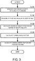
- the processing device may execute the processing at and after Step S103 of a flowchart illustrated in Fig. 3.
- Fig. 3 is a flowchart illustrating a method of calculating the movable body information according to Embodiment 1 of the present disclosure. Note that, since the processing of each step is described in detail above, detailed description is omitted below.
- each of the plurality of compound sensors measures the position Pw and the velocity Vn of the corresponding sensor (Step S101). Moreover, the plurality of compound sensors measure the attitude AA and the angular velocity ⁇ b of the hull 100 (Step SI02).
- the processing device uses the positions Pw, the velocities Vn, and the angular velocities ⁇ b to calculate the center-of-gravity position PGw and the center-of-gravity velocity VGn (Step S103).
- the processing device uses the center-of-gravity velocity VGn and the angular velocity ⁇ b to calculate the turning radius vector Rb (Step S104).
- the processing device uses the turning radius vector Rb and the center-of-gravity position PGw to calculate the turning center position TC. Moreover, the processing device uses the one-component turning radius vector Rb1 of the turning radius vector Rb, and the center-of-gravity position PGw to calculate the pivoting position RC (Step S105).
- the center-of-gravity information calculating module 50 may calculate the center-of-gravity position PGw and the center-of-gravity velocity VGn as follows.
- the center-of-gravity information calculating module 50 acquires a vector Db between the center of gravity and the sensor based on a designed shape of the hull, etc.
- the vector Db between the center of gravity and the sensor indicates the position of the compound sensor on the basis of the center-of-gravity position PGw.
- the vector Db between the center of gravity and the sensor is indicated in the movable body coordinate system.
- the center-of-gravity information calculating module 50 calculates the center-of-gravity position PGw using a position PG measured by the positioning sensor, the vector Db between the center of gravity and the sensor, and the following equation.
- Pw PGw + C n w ⁇ C b n ⁇ Db
- the center-of-gravity information calculating module 50 calculates the center-of-gravity velocity VGn using the velocity Vn measured by the velocity sensor, the angular velocity ⁇ b measured by the attitude sensor, the vector Db between the center of gravity and the sensor, and the following equation.
- Vn VGn + C b n ⁇ ⁇ b ⁇ Db
- the center-of-gravity position PGw and the center-of-gravity velocity VGn can be calculated. According to this, the turning center position TC and the pivoting position RC can be calculated.
- the turning center position TC and the pivoting position RC are calculated in the geodetic coordinate system.
- the turning center position TC and the pivoting position RC may be calculated in the movable body coordinate system.
- the turning center position TC and the pivoting position RC can be calculated also in the movable body coordinate system.
- the turning center position TC and the pivoting position RC can be calculated for not only one time point, but also for a plurality of time points in the future.
- the calculated pivoting position RC may be set as a new center-of-gravity position PGw so as to calculate a pivoting position RC of subsequent future.
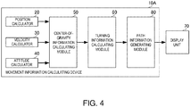
- Fig. 4 is a functional block diagram of the movement information calculating device according to Embodiment 2 of the present disclosure.
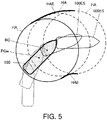
- Fig. 5 is a view illustrating a first example of a display image according to Embodiment 2 of the present disclosure.
- Fig. 6 is a view illustrating a second example of a display image according to Embodiment 2 of the present disclosure.
- the movement information calculating device 10A according to Embodiment 2 is different from the movement information calculating device 10 according to Embodiment 1, in that a path information generating module 80 is added.
- the other configurations of the movement information calculating device 10A are similar to the movement information calculating device 10, and thus, the similar configurations are omitted.
- the path information generating module 80 receives an input of the pivoting position RC from the turning information calculating module 60.
- the path information generating module 80 stores a length of the hull 100 (hull length), and a width of the hull 100 (hull width).
- the path information generating module 80 calculates a hazardous area HA and an estimated hazardous area HAE, based on the pivoting position RC, the hull length, and the hull width. In detail, the path information generating module 80 calculates a circle of which the center is at the pivoting position RC, and a radius is a distance between the pivoting position RC and one of the bow and the stern which is farther from the pivoting position RC (the stern when moving forward). The path information generating module 80 sets this circle as the hazardous area HA. At this time, the path information generating module 80 is preferred to consider the hull width, and calculate the shape of the hazardous area HA as a rotating shape of the hull 100 with the width.
- the path information generating module 80 calculates hazardous areas HA of a plurality of future time points based on the pivoting positions RC at these time points.
- the path information generating module 80 calculates the estimated hazardous area HAE based on the hazardous areas HA at the plurality of time points.
- the path information generating module 80 calculates a curve connecting the hazardous areas HA at the plurality of time points on the starboard side of the hull 100, and a curve connecting the hazardous areas HA at the plurality of time points on the port side of the hull 100.
- the path information generating module 80 calculates an area between the curve on the starboard side and the curve on the port side as the estimated hazardous area HAE.
- the path information generating module 80 generates a display image as illustrated in Fig. 5 , which includes the current center-of-gravity position PGw, the pivoting position RC, the hazardous areas HA, and the estimated hazardous area HAE of the hull 100, and outputs it to the display unit 70.
- the path information generating module 80 may display, for example, a mark indicative of the hull 100, an estimated positional mark(s) 100ES of the hull 100.
- the path information generating module 80 may display a past position of the hull 100.
- an operator can easily grasp the information to be considered when turning the hull 100, such as the hazardous areas HA and the estimated hazardous area HAE at the time of turning.
- the path information generating module 80 may generate a display image as illustrated in Fig. 6 .
- the path information generating module 80 receives inputs of the pivoting position RC, the turning center position TC, and the turning radius vector Rb from the turning information calculating module 60.
- the path information generating module 80 generates the display image as illustrated in Fig. 6 , which includes the pivoting position RC, the turning center position TC, and the turning radius vector Rb, and outputs it to the display unit 70.
- the path information generating module 80 may calculate a clearance circle CC which is estimated based on the turning center position TC and the turning radius vector Rb, and include it in the display image as illustrated in Fig. 6 .
- the path information generating module 80 may display, as illustrated in Fig. 6 , the estimated positional mark(s) 100ES of the hull 100, and a hull positional mark(s) 100BC in the past.
- the operator can easily grasp the information to be considered when turning.
- the velocity may be calculated based on the temporal change in the position acquired by the positioning sensor.
- the velocity sensor may be omitted.
- the function of the velocity calculator may be substituted by the positioning sensor or the center-of-gravity information calculating module 50.
- All of the processes described herein may be embodied in, and fully automated via, software code modules executed by a computing system that includes one or more computers or processors.
- the code modules may be stored in any type of non-transitory computer-readable medium or other computer storage device. Some or all the methods may be embodied in specialized computer hardware.
- a processor can be a microprocessor, but in the alternative, the processor can be a controller, microcontroller, or state machine, combinations of the same, or the like.
- a processor can include electrical circuitry configured to process computer-executable instructions.
- a processor includes an application specific integrated circuit (ASIC), a field programmable gate array (FPGA) or other programmable device that performs logic operations without processing computer-executable instructions.
- ASIC application specific integrated circuit
- FPGA field programmable gate array
- a processor can also be implemented as a combination of computing devices, e.g., a combination of a digital signal processor (DSP) and a microprocessor, a plurality of microprocessors, one or more microprocessors in conjunction with a DSP core, or any other such configuration.
- DSP digital signal processor
- a processor may also include primarily analog components.
- some or all of the signal processing algorithms described herein may be implemented in analog circuitry or mixed analog and digital circuitry.
- a computing environment can include any type of computer system, including, but not limited to, a computer system based on a microprocessor, a mainframe computer, a digital signal processor, a portable computing device, a device controller, or a computational engine within an appliance, to name a few.
- Disjunctive language such as the phrase "at least one of X, Y, or Z," unless specifically stated otherwise, is otherwise understood with the context as used in general to present that an item, term, etc., may be either X, Y, or Z, or any combination thereof (e.g., X, Y, and/or Z). Thus, such disjunctive language is not generally intended to, and should not, imply that certain embodiments require at least one of X, at least one of Y, or at least one of Z to each be present.
- a device configured to are intended to include one or more recited devices. Such one or more recited devices can also be collectively configured to carry out the stated recitations.
- a processor configured to carry out recitations A, B and C can include a first processor configured to carry out recitation A working in conjunction with a second processor configured to carry out recitations B and C.
- horizontal is defined as a plane parallel to the plane or surface of the floor of the area in which the system being described is used or the method being described is performed, regardless of its orientation.
- floor can be interchanged with the term “ground” or “water surface.”
- vertical refers to a direction perpendicular to the horizontal as just defined. Terms such as “above,” “below,” “bottom,” “top,” “side,” “higher,” “lower,” “upper,” “over,” and “under,” are defined with respect to the horizontal plane.
- connection As used herein, the terms “attached,” “connected,” “mated,” and other such relational terms should be construed, unless otherwise noted, to include removable, moveable, fixed, adjustable, and/or releasable connections or attachments.
- the connections/attachments can include direct connections and/or connections having intermediate structure between the two components discussed.
Landscapes
- Engineering & Computer Science (AREA)
- Radar, Positioning & Navigation (AREA)
- Remote Sensing (AREA)
- Physics & Mathematics (AREA)
- General Physics & Mathematics (AREA)
- Automation & Control Theory (AREA)
- Aviation & Aerospace Engineering (AREA)
- Ocean & Marine Engineering (AREA)
- Navigation (AREA)
- Traffic Control Systems (AREA)
Abstract
Description
- The present disclosure relates to a movement information calculating device, a movement information calculating method, and a movement information calculating program which calculate movement information of a movable body such as a ship, particularly, information related to turning of the movable body.
- Conventionally, various technologies for preventing a collision of a movable body such as a ship are put into practical use. Among these, various devices which estimate a path of the movable body and display the estimated path, are put into practical use.
- For example, a display apparatus of Patent Document 1 measures a velocity, a direction, and a turning angular velocity of a movable body so as to calculate a movement track in the past and an estimated track in the future. The display apparatus of Patent Document 1 displays both of the movement path in the past and the estimated path in the future.
- [Patent Document 1]
WO1993/007448A1 - However, the information acquired by the devices contrived in the past, such as the display apparatus disclosed in Patent Document 1, may be insufficient as estimation data during turning. Therefore, further data indicating a state of the movable body during turning is demanded.
- Therefore, a purpose of the present disclosure is to further fulfill data which indicates a state of a movable body during turning.
- A movement information calculating device according to the present disclosure includes a position calculator configured to calculate a position of a movable body, a velocity calculator configured to calculate a velocity of the movable body, an attitude calculator configured to calculate an attitude of the movable body, a center-of-gravity information calculating module, and a turning information calculating module. The center-of-gravity information calculating module calculates a center-of-gravity position and a center-of-gravity velocity of the movable body by using the position, the velocity, and the attitude. The turning information calculating module calculates one of a turning center position and a pivoting position of the movable body by using the center-of-gravity position and the center-of-gravity velocity.
- According to this configuration, the turning center position or the pivoting position which indicates the state of the movable body during turning can be calculated by using the position, the velocity, and the attitude of the movable body.
- According to the present disclosure, data which indicates the state of the movable body during turning can further be fulfilled.
-
-
Fig. 1 is a functional block diagram of a movement information calculating device according to Embodiment 1 of the present disclosure. -
Fig. 2 is a plan view illustrating a turning state of a ship. -
Fig. 3 is a flowchart illustrating a method of calculating movable body information according to Embodiment 1 of the present disclosure. -
Fig. 4 is a functional block diagram of a movement information calculating device according to Embodiment 2 of the present disclosure. -
Fig. 5 is a view illustrating a first example of a display image according to Embodiment 2 of the present disclosure. -
Fig. 6 is a view illustrating a second example of a display image according to Embodiment 2 of the present disclosure. - A movement information calculating device, a movement state calculating method, and a movement state calculating program according to Embodiment 1 of the present disclosure are described with reference to the drawings.
Fig. 1 is a functional block diagram of the movement information calculating device according to Embodiment 1 of the present disclosure.Fig. 2 is a plan view illustrating a turning state of a ship. Note that, although a ship is used as a movable body in this embodiment, various moving bodies, such as another water-surface movable body, an underwater movable body, and an aerial movable body are applicable. Configurations of the present disclosure are especially effective for a movable body with a large body such as a hull and a fuselage. - As illustrated in
Fig. 1 , the movementinformation calculating device 10 includes aposition calculator 20, avelocity calculator 30, anattitude calculator 40, a center-of-gravityinformation calculating module 50, and a turninginformation calculating module 60. For example, theposition calculator 20 is implemented by a positioning sensor, thevelocity calculator 30 is implemented by a velocity sensor, and theattitude calculator 40 is implemented by an attitude sensor. The center-of-gravityinformation calculating module 50 and the turninginformation calculating module 60 are implemented by, for example, a storage device which stores a program for executing these functions, and computing elements (e.g., a CPU) which execute the program stored in the storage device. The positioning sensor corresponds to the "position calculator," the velocity sensor corresponds to the "velocity calculator," and the attitude sensor corresponds to the "attitude calculator" of the present disclosure. - The movement
information calculating device 10 is connected to adisplay unit 70. Note that thisdisplay unit 70 may be included in the movementinformation calculating device 10. - The movement
information calculating device 10 and thedisplay unit 70 are equipped in ahull 100 as illustrated inFig. 2 . Thehull 100 is provided withcompound sensors - As illustrated in
Fig. 2 , thecompound sensors hull 100. Thecompound sensors - As illustrated in
Fig. 2 , thecompound sensor 103 is disposed around the bow of thehull 100. In other words, thecompound sensor 103 is disposed at a different position from thecompound sensors hull 100, that is, in an Xb-direction in the Body coordinate system. Note that the arrangement of thecompound sensors hull 100 is also not limited to this. - The
compound sensors compound sensors - According to this configuration, each of the positioning sensors of the
compound sensors information calculating module 50. - Moreover, each of the velocity sensors of the
compound sensors information calculating module 50. - Moreover, each of the attitude sensors of the
compound sensors hull 100, a direction connecting the bow and the stern is the Xb-direction, a direction connecting the starboard and the port is the Yb-direction, and a direction perpendicular to the Xb-direction and the Yb-direction is a Zb-direction. Each attitude sensor outputs the angular velocity ωb to the center-of-gravityinformation calculating module 50. - The center-of-gravity
information calculating module 50 calculates, using the positions Pw, the velocities Vn, and the angular velocities ωb, a center-of-gravity position PGw and a center-of-gravity velocity VGn of thehull 100. In detail, the center-of-gravityinformation calculating module 50 uses the following method to calculate the center-of-gravity position PGw and the center-of-gravity velocity VGn. - The center-of-gravity
information calculating module 50 calculates the center-of-gravity position PGw based on the positions Pw of thecompound sensors information calculating module 50 calculates the center-of-gravity velocity PVn based on the velocities Vn of thecompound sensors compound sensors - The center-of-gravity
information calculating module 50 outputs the center-of-gravity position PGw and the center-of-gravity velocity VGn to the turninginformation calculating module 60. - The turning
information calculating module 60 calculates a turning radius vector Rb. As illustrated inFig. 2 , the turning radius vector Rb is a vector starting at a turning center position TC of thehull 100 and ending at the center-of-gravity position PGw of thehull 100. - Based on the positional relationship illustrated in
Fig. 2 , the turninginformation calculating module 60 calculates the turning radius vector Rb using the center-of-gravity velocity VGn, the angular velocity ωb, and the following equation. The turning radius vector Rb is expressed by three-dimensional components (Rbx, Rby, Rbz) of the movable body coordinate system.
- Note that the Cb n is a transformation matrix from the movable body coordinate system to the NED coordinate system, and can be calculated using the angular velocity ωb in a known method. Moreover, in this Equation 1 and the following equations, "•" indicates an inner product of the vector, and "×" indicates an outer product of the vector.
- The turning
information calculating module 60 calculates a pivoting position RC and the turning center position TC. As illustrated inFig. 2 , the pivoting position RC is a position to be an axis of thehull 100 during the turning. For example, when thehull 100 turns from the bow side, the pivoting position RC is on the bow side of the center-of-gravity position PGw. On the other hand, when thehull 100 turns from the stern side, the pivoting position RC is on the stern side of the center-of-gravity position PGw. Moreover, the turning center position TC is a position indicating the center point of the turning motion of thehull 100. The pivoting position RC and the turning center position TC are indicated in the geodetic coordinate system. - Based on the positional relationship illustrated in
Fig. 2 , the turninginformation calculating module 60 calculates the turning center position TC using the center-of-gravity position PGw, the turning radius vector Rb, and the following equation.
- Moreover, based on the positional relationship illustrated in
Fig. 2 , the turninginformation calculating module 60 calculates the pivoting position RC using the center-of-gravity position PGw, a one-component turning radius vector Rb1, and the following equation.
- Note that Cn w is a transformation matrix from the NED coordinate system to the geodetic coordinate system, and can be calculated based on the position Pw in a known method. Moreover, the one-component turning radius vector Rb1 is composed of an X-direction component of the turning radius vector Rb, and defined by Rb1 = (Rbx, 0, 0).
- The turning
information calculating module 60 outputs to thedisplay unit 70 the turning center position TC and the pivoting position RC calculated in the geodetic coordinate system. Thedisplay unit 70 displays the turning center position TC and the pivoting position RC. At this time, thedisplay unit 70 may display other information related to the hull 100 (e.g., the center-of-gravity position PGw) in addition to the turning center position TC and the pivoting position RC. - As described above, the movement
information calculating device 10 of this embodiment can calculate the turning center position TC and the pivoting position RC related to the turning motion of thehull 100, based on the position Pw measured by the positioning sensors, the velocity Vn measured by the velocity sensors, and the angular velocity ωb measured by the attitude sensors. That is, the turning center position TC and the pivoting position RC can be calculated in the basic configuration where the position, the velocity, and the attitude of thehull 100 are calculated, without a sensor etc. for measuring the turning center position TC and the pivoting position RC being provided. - According to this configuration, the information required during the turning of the
hull 100 is fulfilled. - In the above description, each processing for calculating the turning center position TC and the pivoting position RC is executed by a separated functional part. However, each processing after the calculation of the center-of-gravity position PGw and the center-of-gravity velocity VGn may be stored in a storing module by being programmed, and implemented by the program being executed by a processing device such as a computer. In this case, the processing device may execute the processing at and after Step S103 of a flowchart illustrated in
Fig. 3. Fig. 3 is a flowchart illustrating a method of calculating the movable body information according to Embodiment 1 of the present disclosure. Note that, since the processing of each step is described in detail above, detailed description is omitted below. - First, each of the plurality of compound sensors measures the position Pw and the velocity Vn of the corresponding sensor (Step S101). Moreover, the plurality of compound sensors measure the attitude AA and the angular velocity ωb of the hull 100 (Step SI02).
- The processing device uses the positions Pw, the velocities Vn, and the angular velocities ωb to calculate the center-of-gravity position PGw and the center-of-gravity velocity VGn (Step S103).
- The processing device uses the center-of-gravity velocity VGn and the angular velocity ωb to calculate the turning radius vector Rb (Step S104).
- The processing device uses the turning radius vector Rb and the center-of-gravity position PGw to calculate the turning center position TC. Moreover, the processing device uses the one-component turning radius vector Rb1 of the turning radius vector Rb, and the center-of-gravity position PGw to calculate the pivoting position RC (Step S105).
- Note that, although three compound sensors are used in the above description, one compound sensor may be used. In this case, the center-of-gravity
information calculating module 50 may calculate the center-of-gravity position PGw and the center-of-gravity velocity VGn as follows. - The center-of-gravity
information calculating module 50 acquires a vector Db between the center of gravity and the sensor based on a designed shape of the hull, etc. The vector Db between the center of gravity and the sensor indicates the position of the compound sensor on the basis of the center-of-gravity position PGw. The vector Db between the center of gravity and the sensor is indicated in the movable body coordinate system. - The center-of-gravity
information calculating module 50 calculates the center-of-gravity position PGw using a position PG measured by the positioning sensor, the vector Db between the center of gravity and the sensor, and the following equation.
- Moreover, the center-of-gravity
information calculating module 50 calculates the center-of-gravity velocity VGn using the velocity Vn measured by the velocity sensor, the angular velocity ωb measured by the attitude sensor, the vector Db between the center of gravity and the sensor, and the following equation.
- As described above, even if the number of compound sensor is one, that is, the number of each of the positioning sensor, the velocity sensor, and the attitude sensor is one, the center-of-gravity position PGw and the center-of-gravity velocity VGn can be calculated. According to this, the turning center position TC and the pivoting position RC can be calculated.
- Moreover, in the above description, the turning center position TC and the pivoting position RC are calculated in the geodetic coordinate system. However, the turning center position TC and the pivoting position RC may be calculated in the movable body coordinate system. In this case, when setting the center-of-gravity position PGw as a reference point (0, 0, 0), a turning center position TCb is calculated based on the following equation.

- Moreover, the pivoting position RC is calculated based on the following equation.

- As described above, the turning center position TC and the pivoting position RC can be calculated also in the movable body coordinate system.
- Note that, in the above description, the turning center position TC and the pivoting position RC can be calculated for not only one time point, but also for a plurality of time points in the future. For example, the calculated pivoting position RC may be set as a new center-of-gravity position PGw so as to calculate a pivoting position RC of subsequent future.
- Next, a movement information calculating device according to Embodiment 2 of the present disclosure is described with reference to the drawings.
Fig. 4 is a functional block diagram of the movement information calculating device according to Embodiment 2 of the present disclosure.Fig. 5 is a view illustrating a first example of a display image according to Embodiment 2 of the present disclosure.Fig. 6 is a view illustrating a second example of a display image according to Embodiment 2 of the present disclosure. - As illustrated in
Fig. 4 , the movementinformation calculating device 10A according to Embodiment 2 is different from the movementinformation calculating device 10 according to Embodiment 1, in that a pathinformation generating module 80 is added. The other configurations of the movementinformation calculating device 10A are similar to the movementinformation calculating device 10, and thus, the similar configurations are omitted. - The path
information generating module 80 receives an input of the pivoting position RC from the turninginformation calculating module 60. The pathinformation generating module 80 stores a length of the hull 100 (hull length), and a width of the hull 100 (hull width). - The path
information generating module 80 calculates a hazardous area HA and an estimated hazardous area HAE, based on the pivoting position RC, the hull length, and the hull width. In detail, the pathinformation generating module 80 calculates a circle of which the center is at the pivoting position RC, and a radius is a distance between the pivoting position RC and one of the bow and the stern which is farther from the pivoting position RC (the stern when moving forward). The pathinformation generating module 80 sets this circle as the hazardous area HA. At this time, the pathinformation generating module 80 is preferred to consider the hull width, and calculate the shape of the hazardous area HA as a rotating shape of thehull 100 with the width. - Moreover, the path
information generating module 80 calculates hazardous areas HA of a plurality of future time points based on the pivoting positions RC at these time points. The pathinformation generating module 80 calculates the estimated hazardous area HAE based on the hazardous areas HA at the plurality of time points. In detail, the pathinformation generating module 80 calculates a curve connecting the hazardous areas HA at the plurality of time points on the starboard side of thehull 100, and a curve connecting the hazardous areas HA at the plurality of time points on the port side of thehull 100. The pathinformation generating module 80 calculates an area between the curve on the starboard side and the curve on the port side as the estimated hazardous area HAE. - The path
information generating module 80 generates a display image as illustrated inFig. 5 , which includes the current center-of-gravity position PGw, the pivoting position RC, the hazardous areas HA, and the estimated hazardous area HAE of thehull 100, and outputs it to thedisplay unit 70. At this time, as illustrated inFig. 5 , the pathinformation generating module 80 may display, for example, a mark indicative of thehull 100, an estimated positional mark(s) 100ES of thehull 100. Moreover, the pathinformation generating module 80 may display a past position of thehull 100. - According to such a display, an operator can easily grasp the information to be considered when turning the
hull 100, such as the hazardous areas HA and the estimated hazardous area HAE at the time of turning. - Moreover, the path
information generating module 80 may generate a display image as illustrated inFig. 6 . The pathinformation generating module 80 receives inputs of the pivoting position RC, the turning center position TC, and the turning radius vector Rb from the turninginformation calculating module 60. The pathinformation generating module 80 generates the display image as illustrated inFig. 6 , which includes the pivoting position RC, the turning center position TC, and the turning radius vector Rb, and outputs it to thedisplay unit 70. At this time, the pathinformation generating module 80 may calculate a clearance circle CC which is estimated based on the turning center position TC and the turning radius vector Rb, and include it in the display image as illustrated inFig. 6 . Moreover, the pathinformation generating module 80 may display, as illustrated inFig. 6 , the estimated positional mark(s) 100ES of thehull 100, and a hull positional mark(s) 100BC in the past. - According to such a display, the operator can easily grasp the information to be considered when turning.
- Note that the velocity may be calculated based on the temporal change in the position acquired by the positioning sensor. In this case, the velocity sensor may be omitted. Furthermore, in this case, the function of the velocity calculator may be substituted by the positioning sensor or the center-of-gravity
information calculating module 50. -
- 10, 10A
- Movement Information Calculating Device
- 20
- Position Calculator
- 30
- Velocity Calculator
- 40
- Attitude Calculator
- 50
- Center-of-gravity Information Calculating Module
- 60
- Turning Information Calculating Module
- 70
- Display Unit
- 80
- Path Information Generating Module
- 100
- Hull
- 100BC
- Hull Positional Mark
- 100ES
- Estimated Positional Mark
- 101, 102, 103
- Compound Sensor
- AA
- Attitude
- CC
- Clearance Circle
- COG
- Ship Ground Speed
- Db
- Vector Between Center-of-gravity and Sensor
- HA
- Hazardous Area
- HAE
- Estimated Hazardous Area
- PG
- Position
- PGw
- Center-of-gravity Position
- PVn
- Center-of-gravity Velocity
- Pw
- Position
- Rb
- Turning Radius Vector
- Rb1
- One-component Turning Radius Vector
- RC
- Pivoting Position
- TC
- Turning Center Position
- TCb
- Turning Center Position
- VGn
- Center-of-gravity Velocity
- Vn
- Velocity
- It is to be understood that not necessarily all objects or advantages may be achieved in accordance with any particular embodiment described herein. Thus, for example, those skilled in the art will recognize that certain embodiments may be configured to operate in a manner that achieves or optimizes one advantage or group of advantages as taught herein without necessarily achieving other objects or advantages as may be taught or suggested herein.
- All of the processes described herein may be embodied in, and fully automated via, software code modules executed by a computing system that includes one or more computers or processors. The code modules may be stored in any type of non-transitory computer-readable medium or other computer storage device. Some or all the methods may be embodied in specialized computer hardware.
- Many other variations than those described herein will be apparent from this disclosure. For example, depending on the embodiment, certain acts, events, or functions of any of the algorithms described herein can be performed in a different sequence, can be added, merged, or left out altogether (e.g., not all described acts or events are necessary for the practice of the algorithms). Moreover, in certain embodiments, acts or events can be performed concurrently, e.g., through multi-threaded processing, interrupt processing, or multiple processors or processor cores or on other parallel architectures, rather than sequentially. In addition, different tasks or processes can be performed by different machines and/or computing systems that can function together.
- The various illustrative logical blocks and modules described in connection with the embodiments disclosed herein can be implemented or performed by a machine, such as a processor. A processor can be a microprocessor, but in the alternative, the processor can be a controller, microcontroller, or state machine, combinations of the same, or the like. A processor can include electrical circuitry configured to process computer-executable instructions. In another embodiment, a processor includes an application specific integrated circuit (ASIC), a field programmable gate array (FPGA) or other programmable device that performs logic operations without processing computer-executable instructions. A processor can also be implemented as a combination of computing devices, e.g., a combination of a digital signal processor (DSP) and a microprocessor, a plurality of microprocessors, one or more microprocessors in conjunction with a DSP core, or any other such configuration. Although described herein primarily with respect to digital technology, a processor may also include primarily analog components. For example, some or all of the signal processing algorithms described herein may be implemented in analog circuitry or mixed analog and digital circuitry. A computing environment can include any type of computer system, including, but not limited to, a computer system based on a microprocessor, a mainframe computer, a digital signal processor, a portable computing device, a device controller, or a computational engine within an appliance, to name a few.
- Conditional language such as, among others, "can," "could," "might" or "may," unless specifically stated otherwise, are otherwise understood within the context as used in general to convey that certain embodiments include, while other embodiments do not include, certain features, elements and/or steps. Thus, such conditional language is not generally intended to imply that features, elements and/or steps are in any way required for one or more embodiments or that one or more embodiments necessarily include logic for deciding whether these features, elements and/or steps are included or are to be performed in any particular embodiment.
- Disjunctive language such as the phrase "at least one of X, Y, or Z," unless specifically stated otherwise, is otherwise understood with the context as used in general to present that an item, term, etc., may be either X, Y, or Z, or any combination thereof (e.g., X, Y, and/or Z). Thus, such disjunctive language is not generally intended to, and should not, imply that certain embodiments require at least one of X, at least one of Y, or at least one of Z to each be present.
- Any process descriptions, elements or blocks in the flow diagrams described herein and/or depicted in the attached figures should be understood as potentially representing modules, segments, or portions of code which include one or more executable instructions for implementing specific logical functions or elements in the process. Alternate implementations are included within the scope of the embodiments described herein in which elements or functions may be deleted, executed out of order from that shown, or discussed, including substantially concurrently or in reverse order, depending on the functionality involved as would be understood by those skilled in the art.
- Unless otherwise explicitly stated, articles such as "a" or "an" should generally be interpreted to include one or more described items. Accordingly, phrases such as "a device configured to" are intended to include one or more recited devices. Such one or more recited devices can also be collectively configured to carry out the stated recitations. For example, "a processor configured to carry out recitations A, B and C" can include a first processor configured to carry out recitation A working in conjunction with a second processor configured to carry out recitations B and C. In addition, even if a specific number of an introduced embodiment recitation is explicitly recited, those skilled in the art will recognize that such recitation should typically be interpreted to mean at least the recited number (e.g., the bare recitation of "two recitations," without other modifiers, typically means at least two recitations, or two or more recitations).
- It will be understood by those within the art that, in general, terms used herein, are generally intended as "open" terms (e.g., the term "including" should be interpreted as "including but not limited to," the term "having" should be interpreted as "having at least," the term "includes" should be interpreted as "includes but is not limited to," etc.).
- For expository purposes, the term "horizontal" as used herein is defined as a plane parallel to the plane or surface of the floor of the area in which the system being described is used or the method being described is performed, regardless of its orientation. The term "floor" can be interchanged with the term "ground" or "water surface." The term "vertical" refers to a direction perpendicular to the horizontal as just defined. Terms such as "above," "below," "bottom," "top," "side," "higher," "lower," "upper," "over," and "under," are defined with respect to the horizontal plane.
- As used herein, the terms "attached," "connected," "mated," and other such relational terms should be construed, unless otherwise noted, to include removable, moveable, fixed, adjustable, and/or releasable connections or attachments. The connections/attachments can include direct connections and/or connections having intermediate structure between the two components discussed.
- Unless otherwise noted, numbers preceded by a term such as "approximately," "about," and "substantially" as used herein include the recited numbers, and also represent an amount close to the stated amount that still performs a desired function or achieves a desired result. For example, the terms "approximately," "about," and "substantially" may refer to an amount that is within less than 10% of the stated amount. Features of embodiments disclosed herein preceded by a term such as "approximately," "about," and "substantially" as used herein represent the feature with some variability that still performs a desired function or achieves a desired result for that feature.
- It should be emphasized that many variations and modifications may be made to the above-described embodiments, the elements of which are to be understood as being among other acceptable examples. All such modifications and variations are intended to be included herein within the scope of this disclosure and protected by the following claims.
Claims (7)
- A movement information calculating device, comprising:a position calculator configured to calculate a position of a movable body;a velocity calculator configured to calculate a velocity of the movable body;an attitude calculator configured to calculate an attitude of the movable body;a center-of-gravity information calculating module configured to calculate a center-of-gravity position and a center-of-gravity velocity of the movable body by using the position, the velocity, and the attitude; anda turning information calculating module configured to calculate one of a turning center position and a pivoting position of the movable body by using the center-of-gravity position and the center-of-gravity velocity.
- The movement information calculating device of claim 1, wherein the position calculator includes a plurality of position calculators, and
wherein the center-of-gravity information calculating module calculates vectors indicative of the positions of the plurality of position calculators with respect to the center-of-gravity position by using the positions measured by the position calculators and the attitude, and calculates the center-of-gravity position and the center-of-gravity velocity using the vector. - The movement information calculating device of claim 1 or 2, wherein the position is indicated in the geodetic coordinate system, the velocity is indicated in the NED coordinate system, and the attitude is indicated in a movable body coordinate system, and
wherein the center-of-gravity information calculating module calculates a first coordinate transformation matrix by using the attitude for transforming the coordinate between the movable body coordinate system and the NED coordinate system, calculates a second coordinate transformation matrix by using the position for transforming the coordinate between the NED coordinate system and the movable body coordinate system, and calculates the center-of-gravity position and the center-of-gravity velocity by using the first coordinate transformation matrix and the second coordinate transformation matrix. - The movement information calculating device of claim 1 or 3, comprising a path information generating module configured to generate path information including one of the turning center position and the pivoting position, and the position of the movable body.
- The movement information calculating device of claim 4, wherein the path information generating module calculates a hazardous area or an estimated hazardous area related to a contact of the movable body by using the pivoting position and a shape of the movable body.
- A movement information calculating method, comprising the steps of:calculating a position of a movable body;calculating a velocity of the movable body;calculating an attitude of the movable body;calculating a center-of-gravity position and a center-of-gravity velocity of the movable body by using the position, the velocity, and the attitude; andcalculating one of a turning center position and a pivoting position of the movable body by using the center-of-gravity position and the center-of-gravity velocity.
- A movement information calculating program configured to cause a processing device to execute processing, the processing comprising:calculating a position of a movable body;calculating a velocity of the movable body;calculating an attitude of the movable body;calculating a center-of-gravity position and a center-of-gravity velocity of the movable body by using the position, the velocity, and the attitude; andcalculating one of a turning center position and a pivoting position of the movable body by using the center-of-gravity position and the center-of-gravity velocity.
Applications Claiming Priority (2)
| Application Number | Priority Date | Filing Date | Title |
|---|---|---|---|
| JP2017231709 | 2017-12-01 | ||
| PCT/JP2018/042754 WO2019107213A1 (en) | 2017-12-01 | 2018-11-20 | Movement information calculation device, movement information calculation method, and movement information calculation program |
Publications (2)
| Publication Number | Publication Date |
|---|---|
| EP3734572A1 true EP3734572A1 (en) | 2020-11-04 |
| EP3734572A4 EP3734572A4 (en) | 2021-11-17 |
Family
ID=66664780
Family Applications (1)
| Application Number | Title | Priority Date | Filing Date |
|---|---|---|---|
| EP18883868.4A Withdrawn EP3734572A4 (en) | 2017-12-01 | 2018-11-20 | Movement information calculation device, movement information calculation method, and movement information calculation program |
Country Status (5)
| Country | Link |
|---|---|
| US (1) | US11268814B2 (en) |
| EP (1) | EP3734572A4 (en) |
| JP (1) | JP7023981B2 (en) |
| CN (1) | CN111433827B (en) |
| WO (1) | WO2019107213A1 (en) |
Families Citing this family (1)
| Publication number | Priority date | Publication date | Assignee | Title |
|---|---|---|---|---|
| CN114379718B (en) * | 2021-12-22 | 2023-05-30 | 南京联迪信息系统股份有限公司 | Method and system for early warning and rescuing in distress of pleasure boat |
Family Cites Families (8)
| Publication number | Priority date | Publication date | Assignee | Title |
|---|---|---|---|---|
| WO1993007448A1 (en) * | 1991-10-04 | 1993-04-15 | Furuno Electric Company, Limited | Display apparatus |
| JPH08119197A (en) * | 1994-10-25 | 1996-05-14 | Yokogawa Denshi Kiki Kk | Automatic steering gear |
| JP3910788B2 (en) * | 2000-08-07 | 2007-04-25 | 株式会社東芝 | Navigation data processing apparatus and navigation data processing method |
| JP4301861B2 (en) | 2002-05-20 | 2009-07-22 | 川崎重工業株式会社 | Method and apparatus for maneuvering moving body |
| JP3760159B2 (en) * | 2003-04-15 | 2006-03-29 | 欣三 井上 | Navigation safety evaluation method, navigation safety evaluation system, and navigation safety evaluation program |
| JP2006044316A (en) | 2004-07-30 | 2006-02-16 | Nissan Motor Co Ltd | Vehicle state quantity detection device |
| US8260477B2 (en) * | 2007-12-04 | 2012-09-04 | King Fahd University Of Petroleum And Minerals | Method and apparatus for tracking center of gravity of air vehicle |
| US9014975B2 (en) * | 2012-05-23 | 2015-04-21 | Vectornav Technologies, Llc | System on a chip inertial navigation system |
-
2018
- 2018-11-20 EP EP18883868.4A patent/EP3734572A4/en not_active Withdrawn
- 2018-11-20 WO PCT/JP2018/042754 patent/WO2019107213A1/en not_active Ceased
- 2018-11-20 JP JP2019557164A patent/JP7023981B2/en active Active
- 2018-11-20 CN CN201880077759.6A patent/CN111433827B/en active Active
-
2020
- 2020-06-01 US US16/889,034 patent/US11268814B2/en active Active
Also Published As
| Publication number | Publication date |
|---|---|
| CN111433827B (en) | 2022-07-22 |
| JPWO2019107213A1 (en) | 2020-12-10 |
| US20200292316A1 (en) | 2020-09-17 |
| JP7023981B2 (en) | 2022-02-22 |
| EP3734572A4 (en) | 2021-11-17 |
| WO2019107213A1 (en) | 2019-06-06 |
| US11268814B2 (en) | 2022-03-08 |
| CN111433827A (en) | 2020-07-17 |
Similar Documents
| Publication | Publication Date | Title |
|---|---|---|
| US12473059B2 (en) | Ship maneuver supporting device and ship maneuver supporting method | |
| CN114258372B (en) | Ship information display system, ship information display method, image generation device, and program | |
| US20230406461A1 (en) | Navigation route planning apparatus and navigation route planning method | |
| US11383813B2 (en) | Automatic steering device, automatic steering method and automatic steering program | |
| EP3889031A1 (en) | Control target generation device and ship-steering control device | |
| JP7313454B2 (en) | RELATIVE POSITION MEASURING DEVICE, RELATIVE POSITION MEASURING METHOD, AND RELATIVE POSITION MEASURING PROGRAM | |
| US20200393574A1 (en) | Navigation device, vslam correcting method, method of estimating spatial information, vslam correcting program, and spatial information estimating program | |
| US12542061B2 (en) | Ship monitoring device, ship monitoring method and a non-transitory computer-readable medium | |
| JP7431194B2 (en) | Tidal flow display device based on augmented reality | |
| US20230296765A1 (en) | Ship monitoring system, ship monitoring method, and information processing device | |
| US20240053150A1 (en) | Ship monitoring system, and ship monitoring method | |
| CN114964244A (en) | Tidal current information display device, AR navigation system, tidal current information display method, and tidal current information display program | |
| US11268814B2 (en) | Movement information calculating device, movement information calculating method and movement information calculating program | |
| CN115019217A (en) | Tidal current display device based on augmented reality | |
| US11156721B2 (en) | Oscillation observation device, oscillation observation method and oscillation observation program | |
| US11255675B2 (en) | Course estimating device, method of estimating course, and course estimating program | |
| EP4290495A1 (en) | Obstruction zone generation device and method | |
| US20260010175A1 (en) | Navigation support device, automatic berthing system, navigation support method, navigation support program | |
| US20250145257A1 (en) | Navigation supporting device, navigation supporting system, navigation supporting method, and computer readable medium | |
| WO2024053524A1 (en) | Navigation assistance device and navigation assistance method | |
| WO2024053525A1 (en) | Navigation assistance device and navigation assistance method | |
| WO2024053526A1 (en) | Navigation assistance device and navigation assistance method |
Legal Events
| Date | Code | Title | Description |
|---|---|---|---|
| STAA | Information on the status of an ep patent application or granted ep patent |
Free format text: STATUS: THE INTERNATIONAL PUBLICATION HAS BEEN MADE |
|
| PUAI | Public reference made under article 153(3) epc to a published international application that has entered the european phase |
Free format text: ORIGINAL CODE: 0009012 |
|
| STAA | Information on the status of an ep patent application or granted ep patent |
Free format text: STATUS: REQUEST FOR EXAMINATION WAS MADE |
|
| 17P | Request for examination filed |
Effective date: 20200902 |
|
| AK | Designated contracting states |
Kind code of ref document: A1 Designated state(s): AL AT BE BG CH CY CZ DE DK EE ES FI FR GB GR HR HU IE IS IT LI LT LU LV MC MK MT NL NO PL PT RO RS SE SI SK SM TR |
|
| AX | Request for extension of the european patent |
Extension state: BA ME |
|
| DAV | Request for validation of the european patent (deleted) | ||
| DAX | Request for extension of the european patent (deleted) | ||
| A4 | Supplementary search report drawn up and despatched |
Effective date: 20211015 |
|
| RIC1 | Information provided on ipc code assigned before grant |
Ipc: G01M 1/12 20060101ALI20211011BHEP Ipc: B63B 49/00 20060101ALI20211011BHEP Ipc: G01C 21/16 20060101ALI20211011BHEP Ipc: G08G 3/02 20060101AFI20211011BHEP |
|
| STAA | Information on the status of an ep patent application or granted ep patent |
Free format text: STATUS: THE APPLICATION IS DEEMED TO BE WITHDRAWN |
|
| 18D | Application deemed to be withdrawn |
Effective date: 20220514 |