EP3734479A1 - Access control apparatus and method for controlling configuration of automation apparatus - Google Patents
Access control apparatus and method for controlling configuration of automation apparatus Download PDFInfo
- Publication number
- EP3734479A1 EP3734479A1 EP19172167.9A EP19172167A EP3734479A1 EP 3734479 A1 EP3734479 A1 EP 3734479A1 EP 19172167 A EP19172167 A EP 19172167A EP 3734479 A1 EP3734479 A1 EP 3734479A1
- Authority
- EP
- European Patent Office
- Prior art keywords
- access
- control apparatus
- user
- access control
- configuration
- Prior art date
- Legal status (The legal status is an assumption and is not a legal conclusion. Google has not performed a legal analysis and makes no representation as to the accuracy of the status listed.)
- Granted
Links
Images


Classifications
-
- G—PHYSICS
- G06—COMPUTING OR CALCULATING; COUNTING
- G06F—ELECTRIC DIGITAL DATA PROCESSING
- G06F21/00—Security arrangements for protecting computers, components thereof, programs or data against unauthorised activity
- G06F21/30—Authentication, i.e. establishing the identity or authorisation of security principals
- G06F21/31—User authentication
- G06F21/34—User authentication involving the use of external additional devices, e.g. dongles or smart cards
- G06F21/35—User authentication involving the use of external additional devices, e.g. dongles or smart cards communicating wirelessly
-
- G—PHYSICS
- G05—CONTROLLING; REGULATING
- G05B—CONTROL OR REGULATING SYSTEMS IN GENERAL; FUNCTIONAL ELEMENTS OF SUCH SYSTEMS; MONITORING OR TESTING ARRANGEMENTS FOR SUCH SYSTEMS OR ELEMENTS
- G05B19/00—Program-control systems
- G05B19/02—Program-control systems electric
- G05B19/418—Total factory control, i.e. centrally controlling a plurality of machines, e.g. direct or distributed numerical control [DNC], flexible manufacturing systems [FMS], integrated manufacturing systems [IMS] or computer integrated manufacturing [CIM]
- G05B19/4183—Total factory control, i.e. centrally controlling a plurality of machines, e.g. direct or distributed numerical control [DNC], flexible manufacturing systems [FMS], integrated manufacturing systems [IMS] or computer integrated manufacturing [CIM] characterised by data acquisition, e.g. workpiece identification
-
- G—PHYSICS
- G05—CONTROLLING; REGULATING
- G05B—CONTROL OR REGULATING SYSTEMS IN GENERAL; FUNCTIONAL ELEMENTS OF SUCH SYSTEMS; MONITORING OR TESTING ARRANGEMENTS FOR SUCH SYSTEMS OR ELEMENTS
- G05B19/00—Program-control systems
- G05B19/02—Program-control systems electric
- G05B19/418—Total factory control, i.e. centrally controlling a plurality of machines, e.g. direct or distributed numerical control [DNC], flexible manufacturing systems [FMS], integrated manufacturing systems [IMS] or computer integrated manufacturing [CIM]
- G05B19/4185—Total factory control, i.e. centrally controlling a plurality of machines, e.g. direct or distributed numerical control [DNC], flexible manufacturing systems [FMS], integrated manufacturing systems [IMS] or computer integrated manufacturing [CIM] characterised by the network communication
-
- G—PHYSICS
- G05—CONTROLLING; REGULATING
- G05B—CONTROL OR REGULATING SYSTEMS IN GENERAL; FUNCTIONAL ELEMENTS OF SUCH SYSTEMS; MONITORING OR TESTING ARRANGEMENTS FOR SUCH SYSTEMS OR ELEMENTS
- G05B19/00—Program-control systems
- G05B19/02—Program-control systems electric
- G05B19/418—Total factory control, i.e. centrally controlling a plurality of machines, e.g. direct or distributed numerical control [DNC], flexible manufacturing systems [FMS], integrated manufacturing systems [IMS] or computer integrated manufacturing [CIM]
- G05B19/41865—Total factory control, i.e. centrally controlling a plurality of machines, e.g. direct or distributed numerical control [DNC], flexible manufacturing systems [FMS], integrated manufacturing systems [IMS] or computer integrated manufacturing [CIM] characterised by job scheduling, process planning, material flow
-
- G—PHYSICS
- G05—CONTROLLING; REGULATING
- G05B—CONTROL OR REGULATING SYSTEMS IN GENERAL; FUNCTIONAL ELEMENTS OF SUCH SYSTEMS; MONITORING OR TESTING ARRANGEMENTS FOR SUCH SYSTEMS OR ELEMENTS
- G05B19/00—Program-control systems
- G05B19/02—Program-control systems electric
- G05B19/418—Total factory control, i.e. centrally controlling a plurality of machines, e.g. direct or distributed numerical control [DNC], flexible manufacturing systems [FMS], integrated manufacturing systems [IMS] or computer integrated manufacturing [CIM]
- G05B19/4188—Total factory control, i.e. centrally controlling a plurality of machines, e.g. direct or distributed numerical control [DNC], flexible manufacturing systems [FMS], integrated manufacturing systems [IMS] or computer integrated manufacturing [CIM] characterised by CIM planning or realisation
-
- G—PHYSICS
- G05—CONTROLLING; REGULATING
- G05B—CONTROL OR REGULATING SYSTEMS IN GENERAL; FUNCTIONAL ELEMENTS OF SUCH SYSTEMS; MONITORING OR TESTING ARRANGEMENTS FOR SUCH SYSTEMS OR ELEMENTS
- G05B19/00—Program-control systems
- G05B19/02—Program-control systems electric
- G05B19/418—Total factory control, i.e. centrally controlling a plurality of machines, e.g. direct or distributed numerical control [DNC], flexible manufacturing systems [FMS], integrated manufacturing systems [IMS] or computer integrated manufacturing [CIM]
- G05B19/41885—Total factory control, i.e. centrally controlling a plurality of machines, e.g. direct or distributed numerical control [DNC], flexible manufacturing systems [FMS], integrated manufacturing systems [IMS] or computer integrated manufacturing [CIM] characterised by modeling, simulation of the manufacturing system
-
- G—PHYSICS
- G06—COMPUTING OR CALCULATING; COUNTING
- G06F—ELECTRIC DIGITAL DATA PROCESSING
- G06F21/00—Security arrangements for protecting computers, components thereof, programs or data against unauthorised activity
- G06F21/30—Authentication, i.e. establishing the identity or authorisation of security principals
- G06F21/305—Authentication, i.e. establishing the identity or authorisation of security principals by remotely controlling device operation
-
- G—PHYSICS
- G06—COMPUTING OR CALCULATING; COUNTING
- G06F—ELECTRIC DIGITAL DATA PROCESSING
- G06F8/00—Arrangements for software engineering
- G06F8/60—Software deployment
- G06F8/65—Updates
-
- H—ELECTRICITY
- H04—ELECTRIC COMMUNICATION TECHNIQUE
- H04L—TRANSMISSION OF DIGITAL INFORMATION, e.g. TELEGRAPHIC COMMUNICATION
- H04L63/00—Network architectures or network communication protocols for network security
- H04L63/08—Network architectures or network communication protocols for network security for authentication of entities
- H04L63/0853—Network architectures or network communication protocols for network security for authentication of entities using an additional device, e.g. smartcard, SIM or a different communication terminal
-
- H—ELECTRICITY
- H04—ELECTRIC COMMUNICATION TECHNIQUE
- H04L—TRANSMISSION OF DIGITAL INFORMATION, e.g. TELEGRAPHIC COMMUNICATION
- H04L63/00—Network architectures or network communication protocols for network security
- H04L63/08—Network architectures or network communication protocols for network security for authentication of entities
- H04L63/0892—Network architectures or network communication protocols for network security for authentication of entities by using authentication-authorization-accounting [AAA] servers or protocols
-
- H—ELECTRICITY
- H04—ELECTRIC COMMUNICATION TECHNIQUE
- H04L—TRANSMISSION OF DIGITAL INFORMATION, e.g. TELEGRAPHIC COMMUNICATION
- H04L63/00—Network architectures or network communication protocols for network security
- H04L63/10—Network architectures or network communication protocols for network security for controlling access to devices or network resources
- H04L63/104—Grouping of entities
-
- H—ELECTRICITY
- H04—ELECTRIC COMMUNICATION TECHNIQUE
- H04L—TRANSMISSION OF DIGITAL INFORMATION, e.g. TELEGRAPHIC COMMUNICATION
- H04L63/00—Network architectures or network communication protocols for network security
- H04L63/10—Network architectures or network communication protocols for network security for controlling access to devices or network resources
- H04L63/108—Network architectures or network communication protocols for network security for controlling access to devices or network resources when the policy decisions are valid for a limited amount of time
-
- H—ELECTRICITY
- H04—ELECTRIC COMMUNICATION TECHNIQUE
- H04L—TRANSMISSION OF DIGITAL INFORMATION, e.g. TELEGRAPHIC COMMUNICATION
- H04L9/00—Cryptographic mechanisms or cryptographic arrangements for secret or secure communications; Network security protocols
- H04L9/32—Cryptographic mechanisms or cryptographic arrangements for secret or secure communications; Network security protocols including means for verifying the identity or authority of a user of the system or for message authentication, e.g. authorization, entity authentication, data integrity or data verification, non-repudiation, key authentication or verification of credentials
- H04L9/3234—Cryptographic mechanisms or cryptographic arrangements for secret or secure communications; Network security protocols including means for verifying the identity or authority of a user of the system or for message authentication, e.g. authorization, entity authentication, data integrity or data verification, non-repudiation, key authentication or verification of credentials involving additional secure or trusted devices, e.g. TPM, smartcard, USB or software token
-
- G—PHYSICS
- G05—CONTROLLING; REGULATING
- G05B—CONTROL OR REGULATING SYSTEMS IN GENERAL; FUNCTIONAL ELEMENTS OF SUCH SYSTEMS; MONITORING OR TESTING ARRANGEMENTS FOR SUCH SYSTEMS OR ELEMENTS
- G05B2219/00—Program-control systems
- G05B2219/30—Nc systems
- G05B2219/31—From computer integrated manufacturing till monitoring
- G05B2219/31088—Network communication between supervisor and cell, machine group
Definitions
- Various example embodiments relate to an access control apparatus for controlling a configuration of an automation apparatus, and an access control method for controlling a configuration of an automation apparatus.
- Automation apparatuses are used in process control and automation solutions of various industries. As sites may be large and/or distributed, configuration of automation apparatuses is a demanding task (in view of technical implementation, usabilility, data security, etc.). Further sophistication is clearly desirable.
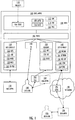
- FIG. 1 which illustrates example embodiments of an access control apparatus 100 for controlling a configuration of an automation apparatus 170
- FIG. 2 illustrates example embodiments of an access control method for controlling the configuration of the automation apparatus 170.
- the automation apparatus 170 may be used in process control and automation solutions of numerous industries including, but not limited to: aluminium production, buiding and facilities, cement and glass, chemicals, data center automation, energy and utilities, food and beverage manufacturing, marine vessel management, metals processing, mining and minerals processing, oil, gas and petrochemical, original equipment manufacturers, pharmaceutical and life sciences, printing newspapers, ports, pulp and paper manufacturing, road and tunnel infrastructure, water and wastewater.
- industries including, but not limited to: aluminium production, buiding and facilities, cement and glass, chemicals, data center automation, energy and utilities, food and beverage manufacturing, marine vessel management, metals processing, mining and minerals processing, oil, gas and petrochemical, original equipment manufacturers, pharmaceutical and life sciences, printing newspapers, ports, pulp and paper manufacturing, road and tunnel infrastructure, water and wastewater.
- the access control apparatus 100 comprises a user interface 140 configured to interact with a local user 180.
- the user interface 140 is configured to implement exchange of graphical, textual and/or auditory information with the local user 180.
- the user interface 140 may be realized with various techniques, such as a display, touch pad, touch-screen, loudspeaker, keyboard/keypad/push buttons/rotary buttons, speech recognition system enabling audio control, cursor control device (mouse, track ball, arrow keys, touch sensitive area etc.), haptic feedback technology, etc.
- the user interface 140 is implemented with a separate panel such as an Internet of things (IoT) panel with an integrated NFC reader.
- IoT Internet of things
- the local user 180 may be a local worker (such as a factory technician) working in an industrial site. There may also be a remote user 196 (such as a service engineer) working in a world-wide or market specific support center of the automation apparatus 170 provider/manufacturer.
- a local worker such as a factory technician
- a remote user 196 such as a service engineer
- the access control apparatus 100 comprises two communication interfaces: an internal communication interface 120 configured to communicate with the automation apparatus 170, and an external communication interface 160 configured to communicate with a network 190.
- the communication interfaces 120, 160 may operate with appropriate wired/wireless communication technologies and standard/proprietary protocols.
- the internal communication interface 120 is configured to communicate with the automation apparatus 170 using one or more of the following: a bus interface 122 (such as an industrial communication bus), a software interface 124 (such as a method call, a message interface, an inter-process communication mechanism), a wired communication interface 126 (such as Ethernet), a wireless communication interface 128 (such as a wireless local area network interface), a short-range wireless transceiver 130 (such as Bluetooth).
- a bus interface 122 such as an industrial communication bus
- a software interface 124 such as a method call, a message interface, an inter-process communication mechanism
- a wired communication interface 126 such as Ethernet
- a wireless communication interface 128 such as a wireless local area network interface
- a short-range wireless transceiver 130 such as Bluetooth
- the external communication interface 160 is configured to communicate with the network 190 using one or more of the following: a wireless local area network (WLAN) 162, a low power wide area network (LPWAN) 164, a narrowband Internet of things (NB-IoT) 166, a cellular radio network 168, a wired network 169 (such as Ethernet).
- WLAN wireless local area network
- LPWAN low power wide area network
- NB-IoT narrowband Internet of things
- cellular radio network 168 such as Ethernet
- wired network 169 such as Ethernet
- the access control apparatus 100 comprises a reader 150 configured to read an electronic tag 182.
- the reader 150 is passive, i.e., the reader 150 only receives radio signals from an active electronic tag 182, which has an own power source.
- the reader 150 is active, i.e., the reader 150 transmits interrogation radio signals, and receives radio signals from a passive electronic tag 182, which is powered by the interrogation signals.
- the reader 150 is configured to read the electronic tag 182 using one or more of the following: near-field communication (NFC) technology 152, Bluetooth technology 154 (also Bluetooth Low Energy BLE), radio-frequency identification (RFID) technology 156.
- NFC near-field communication
- RFID radio-frequency identification
- the NFC technology and the RFID technology enable the use of the passive electronic tags 182, whereas Bluetooth uses active electronic tags 182.
- the electronic tag 182 may be a contactless smart card (such as a proximity card), or a mobile phone with NFC tag functionality, for example.
- the access control apparatus 100 also comprises a processor 102, coupled with the user interface 140, the internal communication interface 120, the external communication interface 160, and the reader 150.
- the processor 102 is configured to cause the control apparatus 100 to perform the access control method for controlling the configuration of the automation apparatus 170.
- the processor 102 may be implemented with one or more processors (such as microprocessors or microcontrollers) 102, and one or more memories 104 including computer program code 106.
- the one or more memories 104 and the computer program code 106 are configured to, with the one or more processors 102, cause performance of data processing operations of the access control apparatus 100.
- the term 'processor' 102 refers to a device that is capable of processing data.
- the access control apparatus 100 may comprise several processors 102 such as parallel processors, a multicore processor, or a computing environment that simultaneously utilizes resources from several physical computer units (sometimes these are referred as cloud, fog or virtualized computing environments).
- processors 102 such as parallel processors, a multicore processor, or a computing environment that simultaneously utilizes resources from several physical computer units (sometimes these are referred as cloud, fog or virtualized computing environments).
- a person skilled in the art will consider the requirements set for the size and power consumption of the control apparatus 100, the necessary processing capacity, production costs, and production volumes, for example.
- a non-exhaustive list of implementation techniques for the processor 102 and the memory 104 includes, but is not limited to: logic components, standard integrated circuits, application-specific integrated circuits (ASIC), system-on-a-chip (SoC), application-specific standard products (ASSP), microprocessors, microcontrollers, digital signal processors, special-purpose computer chips, field-programmable gate arrays (FPGA), and other suitable electronics structures.
- ASIC application-specific integrated circuits
- SoC system-on-a-chip
- ASSP application-specific standard products
- microprocessors microcontrollers
- digital signal processors special-purpose computer chips
- FPGA field-programmable gate arrays
- the working memory and the non-volatile memory may be implemented by a random-access memory (RAM), dynamic RAM (DRAM), static RAM (SRAM), a flash memory, a solid state disk (SSD), PROM (programmable read-only memory), a suitable semiconductor, or any other means of implementing an electrical computer memory.
- the computer program code 106 may be implemented by software.
- the software may be written by a suitable programming language, and the resulting executable code may be stored in the memory 104 and run by the processor 102.
- An example embodiment provides a computer-readable medium 118 storing computer program code 106, which, when loaded into the one or more processors 102 and executed by one or more processors 102, causes the one or more processors 102 to perform the computer-implemented access control method for controlling the configuration of the automation apparatus 170, which will be explained with reference to FIG. 2 .
- the computer-readable medium 118 may comprise at least the following: any entity or device capable of carrying the computer program code 106 to the processor 102, a record medium, a computer memory, a read-only memory, an electrical carrier signal, a telecommunications signal, and a software distribution medium. In some jurisdictions, depending on the legislation and the patent practice, the computer-readable medium 118 may not be the telecommunications signal.
- the computer-readable medium 118 may be a computer-readable storage medium.
- the computer-readable medium 118 may be a non-transitory computer-readable storage medium.
- the method starts in 200, and ends in 210.
- authentication information 108 is read from the electronic tag 182.
- the authentication information 108 is transmitted to a networked service 192.
- the authentication information 108 read from the electronic tag 182 is encrypted and/or signed 212, and the encrypted and/or signed 212 authentication information 108 is transmitted to the networked service 192 for a verification.
- the authentication information 108 may be encrypted by a public key, wherein the networked service 192 has access to a secret decryption key.
- the authentication information 108 may be signed by a digital signature, wherein a signing algorithm has produced the signature by a private key, and a signature verifying algorithm in the networked service 192 checks with a public key that the authentication information 108 and the signature are authentic.
- access rights 110 are received from the networked service 192.
- the access rights 110 received from the networked service 192 are encrypted and/or signed 224. Technologies similar to encrypting and/or signing the authentication information 108 may be used for the access rights 110 as well.
- the access rights 110 are received from the networked service 110 for a role 216 of a user.
- the access rights 110 comprise a definition for a period 214 during which the configuration of the automation apparatus 170 according to the access rights 110 is allowable.
- the period 214 may be expressed in minutes, such as 15, 30 or 60 minutes, for example.
- the configuration of the automation apparatus 170 is controlled according to the access rights 110.
- the control may enable one or more user configuration operations and/or disable one or more user configuration operations.
- controlling 208 the configuration of the automation apparatus 170 according to the access rights 110 comprises one or more of the following: a software update 112 for the automation apparatus 170, a firmware update 114 for the automation apparatus 170, a manipulation (such as reading, and/or writing and/or updating) of one or more operation parameters 116 for the automation apparatus 170.
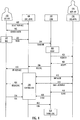
- the configuration of the automation apparatus may be made in two different ways: solely by the local user 180 as illustrated in FIG. 3 , or by a cooperation of the local user 180 and the remote user 196 as illustrated in FIG. 4 .
- FIG. 3 illustrates the local configuration by the local user 180.
- the local user 180 selects 300 the local access from the user interface 140 of the access control apparatus 100.
- the user interface 140 requests 302 authentication from the local user 180.
- the local user 180 uses the electronic tag 182 so that the authentication information 108 is read 202 from the electronic tag 182, and transmitted 204 to the networked service 192.
- the networked service 192 may verify 304 the authentication information 108.
- the access control apparatus 100 receives 206 the access rights 110 from the networked service 192, opens 306 access for the local user 180 according to the access rights 110, and informs 308 the local user 180 of the access rights 110.
- the local user 180 then performs 310 access, during which the configuration of the automation apparatus 170 is controlled 208 according to the access rights 110.
- the local user 312 may close 312 the access.
- a change log is transmitted 316 from the access control apparatus 100 to the networked service 192, and the networked service 192 stores 318 the change log.
- the access rights 110 are received from the networked service 192 for a role 218 of the local user 180.
- the configuration of the automation apparatus 170 is controlled 208 according to the access rights 110 (including the role 218 of the local user 180) during the local access 310 by the local user 180.
- the local access 310 is performed using the user interface 140, and/or via the external communication interface 160, and/or via the reader 150.
- the local user 180 may thus manipulate the user interface 140 according to the role 218.
- the local user 180 may perform the configuration by manipulating the active electronic tag 182.
- the local user 180 may also possess a user apparatus 184, and perform the configuration by manipulating the user apparatus 184.
- FIG. 4 illustrates the co-operative remote configuration by the local user 180 and the remote user 196.
- the local user 180 selects 400 the remote access from the user interface 140 of the access control apparatus 100.
- the user interface 140 requests 402 authentication from the local user 180.
- the local user 180 uses the electronic tag 182 so that the authentication information 108 is read 202 from the electronic tag 182, and transmitted 204 to the networked service 192.
- the networked service 192 may verify 404 the authentication information 108.
- the remote user 192 may manipulate a remote user apparatus 194 in order to perform the configuration.
- the networked server 192 requests 406 the remote user apparatus 194 to join the configuration session, and receives an acceptance 408 from the remote user apparatus 194.
- the access control apparatus 100 receives 206 the access rights 110 from the networked service 192, and informs 410 the local user 180 of the access rights 110.
- the control 208 of the access rights comprises messaging 416 between the local user 180 (using the user interface 140 and/or the local user apparatus 184), an initiatilization 412 of the communication connection between the access control apparatus 100 and the remote user apparatus 194, and data exchange 414 between the access control apparatus 100 and the remote user apparatus 194.
- the remote user apparatus 194 may close 418, 420 the remote access directly or via the networked service 192, or the local user 180 may terminate 226 the remote access.
- the change log is transmitted 422 from the access control apparatus 100 to the networked service 192, and the networked service 192 stores 424 the change log.
- the access rights 110 are received from the networked service 192 for a role 220 of the remote user 196.
- the configuration of the automation apparatus 170 is controlled 208 according to the access rights 110 (including the role 220 of the remote user 196) during the remote access by the remote user 196.
- the remote access is performed via the external communication interface 160.
- the access rights 110 may also be received from the networked service 192 for the role 218 of the local user 180, and the access control for the local user 180 may be performed as in the example embodiment of FIG. 3 .
- the access rights 110 received from the networked service 192 for the role 220 of the remote user 196 may comprise contact information 222.
- the communication session may be initiated via the external communication interface 160 for the remote access based on the contact information 222.
- the contact information 222 may comprise a network address (such an Internet Protocol IP address) to which the access control apparatus 100 opens a birectional communication connection.
- the remote access may be terminated 226 as a result of a user interaction via the user interface 140 by the local user 180.
- the local user 140 may supervise the remote configuration, and if something erroneous or suspicious happens, the remote configuration may be aborted.
- changes made during the configuration of the automation apparatus 170 may be rejected 228 as a result of a user interaction via the user interface 140 by the local user 180.
- the changes may be accepted as a result of a user interaction via the user interface 140 by the local user 180.
- the local user may check that if the remote configuration did not succeed due to configuration errors, malicious behavior, transmission errors, etc., the result of the remote configuration is not taken into use, but the operation of the automation apparatus 170 is continued with the previous configuration.
- the user apparatus 184, 194 may be a computer, laptop computer, tablet computer, phablet, mobile phone, smartphone, general-purpose mobile computing device, or some other electronic apparatus enabling user interaction by the local user 180 and the remote user 196.
- the user apparatus 184, 194 may be a general-purpose off-the-shelf computing device, as opposed to a purpose-build proprietary equipment, whereby research & development costs will be lower as only the special-purpose software (and not the hardware) needs to be designed, implemented and tested.
- the networked service 192 may be implemented by one or more computer servers accessible via the network 190 (which may include a wired network such as the Internet and/or one or more wireless networks such as cellular radio networks).
- the networked service 192 may interoperate with access control apparatus 100 and the user apparatuses 184, 194 according to a client-server architecture, a cloud computing architecture, a peer-to-peer system, or another applicable distributed computing architecture.
Landscapes
- Engineering & Computer Science (AREA)
- Computer Security & Cryptography (AREA)
- General Engineering & Computer Science (AREA)
- General Physics & Mathematics (AREA)
- Physics & Mathematics (AREA)
- Theoretical Computer Science (AREA)
- Computer Hardware Design (AREA)
- Computer Networks & Wireless Communication (AREA)
- Manufacturing & Machinery (AREA)
- Signal Processing (AREA)
- Quality & Reliability (AREA)
- Automation & Control Theory (AREA)
- Software Systems (AREA)
- Computing Systems (AREA)
- Business, Economics & Management (AREA)
- Accounting & Taxation (AREA)
- Telephonic Communication Services (AREA)
Abstract
Description
- Various example embodiments relate to an access control apparatus for controlling a configuration of an automation apparatus, and an access control method for controlling a configuration of an automation apparatus.
- Automation apparatuses are used in process control and automation solutions of various industries. As sites may be large and/or distributed, configuration of automation apparatuses is a demanding task (in view of technical implementation, usabilility, data security, etc.). Further sophistication is clearly desirable.
- According to an aspect, there is provided subject matter of independent claims. Dependent claims define some example embodiments.
- One or more examples of implementations are set forth in more detail in the accompanying drawings and the description of embodiments.
- Some example embodiments will now be described with reference to the accompanying drawings, in which
-
FIG. 1 is a block diagram illustrating example embodiments of an access control apparatus; -
FIG. 2 is a flow-chart illustrating example embodiments of an access control method; and -
FIG. 3 andFIG. 4 are signal sequence charts illustrating example embodiments of the access control apparatus and the access control method. - The following embodiments are only examples. Although the specification may refer to "an" embodiment in several locations, this does not necessarily mean that each such reference is to the same embodiment(s), or that the feature only applies to a single embodiment. Single features of different embodiments may also be combined to provide other embodiments. Furthermore, words "comprising" and "including" should be understood as not limiting the described embodiments to consist of only those features that have been mentioned and such embodiments may contain also features/structures that have not been specifically mentioned.
- Reference numbers, both in the description of the example embodiments and in the claims, serve to illustrate the example embodiments with reference to the drawings, without limiting it to these examples only.
- Let us study simultaneously both
FIG. 1 , which illustrates example embodiments of anaccess control apparatus 100 for controlling a configuration of anautomation apparatus 170, andFIG. 2 , which illustrates example embodiments of an access control method for controlling the configuration of theautomation apparatus 170. - The
automation apparatus 170 may be used in process control and automation solutions of numerous industries including, but not limited to: aluminium production, buiding and facilities, cement and glass, chemicals, data center automation, energy and utilities, food and beverage manufacturing, marine vessel management, metals processing, mining and minerals processing, oil, gas and petrochemical, original equipment manufacturers, pharmaceutical and life sciences, printing newspapers, ports, pulp and paper manufacturing, road and tunnel infrastructure, water and wastewater. - The
access control apparatus 100 comprises auser interface 140 configured to interact with alocal user 180. Theuser interface 140 is configured to implement exchange of graphical, textual and/or auditory information with thelocal user 180. Theuser interface 140 may be realized with various techniques, such as a display, touch pad, touch-screen, loudspeaker, keyboard/keypad/push buttons/rotary buttons, speech recognition system enabling audio control, cursor control device (mouse, track ball, arrow keys, touch sensitive area etc.), haptic feedback technology, etc. In an example embodiment, theuser interface 140 is implemented with a separate panel such as an Internet of things (IoT) panel with an integrated NFC reader. - The
local user 180 may be a local worker (such as a factory technician) working in an industrial site. There may also be a remote user 196 (such as a service engineer) working in a world-wide or market specific support center of theautomation apparatus 170 provider/manufacturer. - The
access control apparatus 100 comprises two communication interfaces: aninternal communication interface 120 configured to communicate with theautomation apparatus 170, and anexternal communication interface 160 configured to communicate with anetwork 190. Thecommunication interfaces - In an example embodiment, the
internal communication interface 120 is configured to communicate with theautomation apparatus 170 using one or more of the following: a bus interface 122 (such as an industrial communication bus), a software interface 124 (such as a method call, a message interface, an inter-process communication mechanism), a wired communication interface 126 (such as Ethernet), a wireless communication interface 128 (such as a wireless local area network interface), a short-range wireless transceiver 130 (such as Bluetooth). - In an example embodiment, the
external communication interface 160 is configured to communicate with thenetwork 190 using one or more of the following: a wireless local area network (WLAN) 162, a low power wide area network (LPWAN) 164, a narrowband Internet of things (NB-IoT) 166, acellular radio network 168, a wired network 169 (such as Ethernet). - The
access control apparatus 100 comprises areader 150 configured to read anelectronic tag 182. In an example embodiment, thereader 150 is passive, i.e., thereader 150 only receives radio signals from an activeelectronic tag 182, which has an own power source. In an alternative example embodiment, thereader 150 is active, i.e., thereader 150 transmits interrogation radio signals, and receives radio signals from a passiveelectronic tag 182, which is powered by the interrogation signals. - In an example embodiment, the
reader 150 is configured to read theelectronic tag 182 using one or more of the following: near-field communication (NFC) technology 152, Bluetooth technology 154 (also Bluetooth Low Energy BLE), radio-frequency identification (RFID)technology 156. The NFC technology and the RFID technology enable the use of the passiveelectronic tags 182, whereas Bluetooth uses activeelectronic tags 182. Theelectronic tag 182 may be a contactless smart card (such as a proximity card), or a mobile phone with NFC tag functionality, for example. - The
access control apparatus 100 also comprises aprocessor 102, coupled with theuser interface 140, theinternal communication interface 120, theexternal communication interface 160, and thereader 150. - The
processor 102 is configured to cause thecontrol apparatus 100 to perform the access control method for controlling the configuration of theautomation apparatus 170. - The
processor 102 may be implemented with one or more processors (such as microprocessors or microcontrollers) 102, and one ormore memories 104 includingcomputer program code 106. The one ormore memories 104 and thecomputer program code 106 are configured to, with the one ormore processors 102, cause performance of data processing operations of theaccess control apparatus 100. - The term 'processor' 102 refers to a device that is capable of processing data. Depending on the processing power needed, the
access control apparatus 100 may compriseseveral processors 102 such as parallel processors, a multicore processor, or a computing environment that simultaneously utilizes resources from several physical computer units (sometimes these are referred as cloud, fog or virtualized computing environments). When designing the implementation of theprocessor 102, a person skilled in the art will consider the requirements set for the size and power consumption of thecontrol apparatus 100, the necessary processing capacity, production costs, and production volumes, for example. - A non-exhaustive list of implementation techniques for the
processor 102 and thememory 104 includes, but is not limited to: logic components, standard integrated circuits, application-specific integrated circuits (ASIC), system-on-a-chip (SoC), application-specific standard products (ASSP), microprocessors, microcontrollers, digital signal processors, special-purpose computer chips, field-programmable gate arrays (FPGA), and other suitable electronics structures. - The term 'memory' 104 refers to a device that is capable of storing data run-time (= working memory) or permanently (= non-volatile memory). The working memory and the non-volatile memory may be implemented by a random-access memory (RAM), dynamic RAM (DRAM), static RAM (SRAM), a flash memory, a solid state disk (SSD), PROM (programmable read-only memory), a suitable semiconductor, or any other means of implementing an electrical computer memory.
- The
computer program code 106 may be implemented by software. In an example embodiment, the software may be written by a suitable programming language, and the resulting executable code may be stored in thememory 104 and run by theprocessor 102. - An example embodiment provides a computer-
readable medium 118 storingcomputer program code 106, which, when loaded into the one ormore processors 102 and executed by one ormore processors 102, causes the one ormore processors 102 to perform the computer-implemented access control method for controlling the configuration of theautomation apparatus 170, which will be explained with reference toFIG. 2 . The computer-readable medium 118 may comprise at least the following: any entity or device capable of carrying thecomputer program code 106 to theprocessor 102, a record medium, a computer memory, a read-only memory, an electrical carrier signal, a telecommunications signal, and a software distribution medium. In some jurisdictions, depending on the legislation and the patent practice, the computer-readable medium 118 may not be the telecommunications signal. In an example embodiment, the computer-readable medium 118 may be a computer-readable storage medium. In an example embodiment, the computer-readable medium 118 may be a non-transitory computer-readable storage medium. - The method starts in 200, and ends in 210.
- In 202,
authentication information 108 is read from theelectronic tag 182. - In 204, the
authentication information 108 is transmitted to a networkedservice 192. - In an example embodiment, the
authentication information 108 read from theelectronic tag 182 is encrypted and/or signed 212, and the encrypted and/or signed 212authentication information 108 is transmitted to the networkedservice 192 for a verification. Theauthentication information 108 may be encrypted by a public key, wherein thenetworked service 192 has access to a secret decryption key. Theauthentication information 108 may be signed by a digital signature, wherein a signing algorithm has produced the signature by a private key, and a signature verifying algorithm in the networkedservice 192 checks with a public key that theauthentication information 108 and the signature are authentic. - In 206,
access rights 110 are received from thenetworked service 192. - In an example embodiment, the
access rights 110 received from thenetworked service 192 are encrypted and/or signed 224. Technologies similar to encrypting and/or signing theauthentication information 108 may be used for theaccess rights 110 as well. - In an example embodiment, the
access rights 110 are received from thenetworked service 110 for arole 216 of a user. - In an example embodiment, the
access rights 110 comprise a definition for aperiod 214 during which the configuration of theautomation apparatus 170 according to theaccess rights 110 is allowable. Theperiod 214 may be expressed in minutes, such as 15, 30 or 60 minutes, for example. - In 208, the configuration of the
automation apparatus 170 is controlled according to theaccess rights 110. The control may enable one or more user configuration operations and/or disable one or more user configuration operations. - In an example embodiment, controlling 208 the configuration of the
automation apparatus 170 according to theaccess rights 110 comprises one or more of the following: asoftware update 112 for theautomation apparatus 170, afirmware update 114 for theautomation apparatus 170, a manipulation (such as reading, and/or writing and/or updating) of one ormore operation parameters 116 for theautomation apparatus 170. - The configuration of the automation apparatus may be made in two different ways: solely by the
local user 180 as illustrated inFIG. 3 , or by a cooperation of thelocal user 180 and the remote user 196 as illustrated inFIG. 4 . - Let us first study
FIG. 3 , which illustrates the local configuration by thelocal user 180. - The
local user 180 selects 300 the local access from theuser interface 140 of theaccess control apparatus 100. As a result of theselection 300, theuser interface 140 requests 302 authentication from thelocal user 180. - The
local user 180 uses theelectronic tag 182 so that theauthentication information 108 is read 202 from theelectronic tag 182, and transmitted 204 to thenetworked service 192. - The
networked service 192 may verify 304 theauthentication information 108. - Then, the
access control apparatus 100 receives 206 theaccess rights 110 from thenetworked service 192, opens 306 access for thelocal user 180 according to theaccess rights 110, and informs 308 thelocal user 180 of theaccess rights 110. - The
local user 180 then performs 310 access, during which the configuration of theautomation apparatus 170 is controlled 208 according to theaccess rights 110. - The
local user 312 may close 312 the access. - As the access is closed 314, a change log is transmitted 316 from the
access control apparatus 100 to thenetworked service 192, and thenetworked service 192stores 318 the change log. - In the example embodiment of
FIG. 3 , theaccess rights 110 are received from thenetworked service 192 for a role 218 of thelocal user 180. The configuration of theautomation apparatus 170 is controlled 208 according to the access rights 110 (including the role 218 of the local user 180) during thelocal access 310 by thelocal user 180. Thelocal access 310 is performed using theuser interface 140, and/or via theexternal communication interface 160, and/or via thereader 150. Thelocal user 180 may thus manipulate theuser interface 140 according to the role 218. Thelocal user 180 may perform the configuration by manipulating the activeelectronic tag 182. Thelocal user 180 may also possess auser apparatus 184, and perform the configuration by manipulating theuser apparatus 184. - Next, let us study
FIG. 4 , which illustrates the co-operative remote configuration by thelocal user 180 and the remote user 196. - The
local user 180 selects 400 the remote access from theuser interface 140 of theaccess control apparatus 100. As a result of theselection 400, theuser interface 140requests 402 authentication from thelocal user 180. - The
local user 180 uses theelectronic tag 182 so that theauthentication information 108 is read 202 from theelectronic tag 182, and transmitted 204 to thenetworked service 192. - The
networked service 192 may verify 404 theauthentication information 108. - As shown in
FIG. 1 , theremote user 192 may manipulate a remote user apparatus 194 in order to perform the configuration. Thenetworked server 192requests 406 the remote user apparatus 194 to join the configuration session, and receives anacceptance 408 from the remote user apparatus 194. - Then, the
access control apparatus 100 receives 206 theaccess rights 110 from thenetworked service 192, and informs 410 thelocal user 180 of theaccess rights 110. - The
control 208 of the access rights comprises messaging 416 between the local user 180 (using theuser interface 140 and/or the local user apparatus 184), aninitiatilization 412 of the communication connection between theaccess control apparatus 100 and the remote user apparatus 194, and data exchange 414 between theaccess control apparatus 100 and the remote user apparatus 194. - The remote user apparatus 194 may close 418, 420 the remote access directly or via the
networked service 192, or thelocal user 180 may terminate 226 the remote access. - The change log is transmitted 422 from the
access control apparatus 100 to thenetworked service 192, and thenetworked service 192stores 424 the change log. - In an example embodiment of
FIG. 4 , theaccess rights 110 are received from thenetworked service 192 for arole 220 of the remote user 196. The configuration of theautomation apparatus 170 is controlled 208 according to the access rights 110 (including therole 220 of the remote user 196) during the remote access by the remote user 196. The remote access is performed via theexternal communication interface 160. - Naturally, in the example embodiment of
FIG. 4 , theaccess rights 110 may also be received from thenetworked service 192 for the role 218 of thelocal user 180, and the access control for thelocal user 180 may be performed as in the example embodiment ofFIG. 3 . - In an example embodiment related to
FIG. 4 , theaccess rights 110 received from thenetworked service 192 for therole 220 of the remote user 196 may comprisecontact information 222. The communication session may be initiated via theexternal communication interface 160 for the remote access based on thecontact information 222. Thecontact information 222 may comprise a network address (such an Internet Protocol IP address) to which theaccess control apparatus 100 opens a birectional communication connection. - In an example embodiment related to
FIG. 4 , the remote access may be terminated 226 as a result of a user interaction via theuser interface 140 by thelocal user 180. In this way, thelocal user 140 may supervise the remote configuration, and if something erroneous or suspicious happens, the remote configuration may be aborted. - In example embodiment related to
FIG. 4 , changes made during the configuration of theautomation apparatus 170 may be rejected 228 as a result of a user interaction via theuser interface 140 by thelocal user 180. Alternatively, the changes may be accepted as a result of a user interaction via theuser interface 140 by thelocal user 180. In this way, the local user may check that if the remote configuration did not succeed due to configuration errors, malicious behavior, transmission errors, etc., the result of the remote configuration is not taken into use, but the operation of theautomation apparatus 170 is continued with the previous configuration. - The
user apparatus 184, 194 may be a computer, laptop computer, tablet computer, phablet, mobile phone, smartphone, general-purpose mobile computing device, or some other electronic apparatus enabling user interaction by thelocal user 180 and the remote user 196. Theuser apparatus 184, 194 may be a general-purpose off-the-shelf computing device, as opposed to a purpose-build proprietary equipment, whereby research & development costs will be lower as only the special-purpose software (and not the hardware) needs to be designed, implemented and tested. - The
networked service 192 may be implemented by one or more computer servers accessible via the network 190 (which may include a wired network such as the Internet and/or one or more wireless networks such as cellular radio networks). Thenetworked service 192 may interoperate withaccess control apparatus 100 and theuser apparatuses 184, 194 according to a client-server architecture, a cloud computing architecture, a peer-to-peer system, or another applicable distributed computing architecture. - Even though the invention has been described with reference to one or more example embodiments according to the accompanying drawings, it is clear that the invention is not restricted thereto but can be modified in several ways within the scope of the appended claims. All words and expressions should be interpreted broadly, and they are intended to illustrate, not to restrict, the example embodiments. It will be obvious to a person skilled in the art that, as technology advances, the inventive concept can be implemented in various ways.
Claims (15)
- An access control apparatus (100) for controlling a configuration of an automation apparatus (170), comprising:a user interface (140) configured to interact with a local user (180);an internal communication interface (120) configured to communicate with the automation apparatus (170);an external communication interface (160) configured to communicate with a network (190);a reader (150) configured to read an electronic tag (182); anda processor (102), coupled with the user interface (140), the internal communication interface (120), the external communication interface (160), and the reader (150), and configured to cause the control apparatus (100) at least to perform:reading (202) authentication information (108) from the electronic tag (182);transmitting (204) the authentication information (108) to a networked service (192);receiving (206) access rights (110) from the networked service (192); andcontrolling (208) the configuration of the automation apparatus (170) according to the access rights (110).
- The access control apparatus of claim 1, wherein the access rights (110) are received from the networked service (110) for a role (216) of a user.
- The access control apparatus of any preceding claim, wherein the access rights (110) comprise a definition for a period (214) during which the configuration of the automation apparatus (170) according to the access rights (110) is allowable.
- The access control apparatus of any preceding claim, wherein the access rights (110) are received from the networked service (192) for a role (218) of the local user (180), the configuration of the automation apparatus (170) is controlled according to the access rights (110) during a local access by the local user (180), and the local access is performed using the user interface (140), and/or via the external communication interface (160), and/or via the reader (150).
- The access control apparatus of any preceding claim, wherein the access rights (110) are received from the networked service (192) for a role (220) of a remote user (196), the configuration of the automation apparatus (170) is controlled according to the access rights (110) during a remote access by the remote user (196), and the remote access is performed via the external communication interface (160).
- The access control apparatus of claim 5, wherein the access rights (110) received from the networked service (192) for the role (220) of the remote user (196) comprise contact information (222), and a communication session is initiated via the external communication interface (160) for the remote access based on the contact information (222).
- The access control apparatus of claim 5 or 6, wherein the remote access is terminated (226) as a result of a user interaction via the user interface (140) by the local user (180).
- The access control apparatus of claim 5 or 6 or 7, wherein changes made during the configuration of the automation apparatus (170) are rejected (228) as a result of a user interaction via the user interface (140) by the local user (180).
- The access control apparatus of any preceding claim, wherein the authentication information (108) read from the electronic tag (182) is encrypted and/or signed (212), and the encrypted and/or signed (212) authentication information (108) is transmitted to the networked service (192) for a verification.
- The access control apparatus of any preceding claim, wherein the access rights (110) received from the networked service (192) are encrypted and/or signed (224).
- The access control apparatus of any preceding claim, wherein controlling (208) the configuration of the automation apparatus (170) according to the access rights (110) comprises one or more of the following: a software update (112) for the automation apparatus (170), a firmware update (114) for the automation apparatus (170), a manipulation of one or more operation parameters (116) for the automation apparatus (170).
- The access control apparatus of any preceding claim, wherein the reader (150) is configured to read the electronic tag (182) using one or more of the following: near-field communication (NFC) technology (152), Bluetooth technology (154), radio-frequency identification (RFID) technology (156).
- The access control apparatus of any preceding claim, wherein the internal communication interface (120) is configured to communicate with the automation apparatus (170) using one or more of the following: a bus interface (122), a software interface (124), a wired communication interface (126), a wireless communication interface (128), a short-range wireless transceiver (130).
- The access control apparatus of any preceding claim, wherein the external communication interface (160) is configured to communicate with the network (190) using one or more of the following: a wireless local area network (WLAN) (162), a low power wide area network (LPWAN) (164), a narrowband Internet of things (NB-IoT) (166), a cellular radio network (168), a wired network (169).
- An access control method for controlling a configuration of an automation apparatus, comprising:reading (202) authentication information from an electronic tag;transmitting (204) the authentication information to a networked service;receiving (206) access rights from the networked service; andcontrolling (208) the configuration of the automation apparatus according to the access rights.
Priority Applications (3)
| Application Number | Priority Date | Filing Date | Title |
|---|---|---|---|
| EP19172167.9A EP3734479B1 (en) | 2019-05-02 | 2019-05-02 | Access control apparatus and method for controlling configuration of automation apparatus |
| CN202010362739.2A CN111880485B (en) | 2019-05-02 | 2020-04-30 | Access control device and method for controlling configuration of automation device |
| US16/864,219 US11693942B2 (en) | 2019-05-02 | 2020-05-01 | Access control apparatus and method for controlling configuration of automation apparatus |
Applications Claiming Priority (1)
| Application Number | Priority Date | Filing Date | Title |
|---|---|---|---|
| EP19172167.9A EP3734479B1 (en) | 2019-05-02 | 2019-05-02 | Access control apparatus and method for controlling configuration of automation apparatus |
Publications (2)
| Publication Number | Publication Date |
|---|---|
| EP3734479A1 true EP3734479A1 (en) | 2020-11-04 |
| EP3734479B1 EP3734479B1 (en) | 2022-10-19 |
Family
ID=66529753
Family Applications (1)
| Application Number | Title | Priority Date | Filing Date |
|---|---|---|---|
| EP19172167.9A Active EP3734479B1 (en) | 2019-05-02 | 2019-05-02 | Access control apparatus and method for controlling configuration of automation apparatus |
Country Status (3)
| Country | Link |
|---|---|
| US (1) | US11693942B2 (en) |
| EP (1) | EP3734479B1 (en) |
| CN (1) | CN111880485B (en) |
Citations (2)
| Publication number | Priority date | Publication date | Assignee | Title |
|---|---|---|---|---|
| US20050097595A1 (en) * | 2003-11-05 | 2005-05-05 | Matti Lipsanen | Method and system for controlling access to content |
| US20100186075A1 (en) * | 2007-09-12 | 2010-07-22 | Abb Technology Ag | Method and system for accessing devices in a secure manner |
Family Cites Families (17)
| Publication number | Priority date | Publication date | Assignee | Title |
|---|---|---|---|---|
| US7167919B2 (en) * | 2001-12-05 | 2007-01-23 | Canon Kabushiki Kaisha | Two-pass device access management |
| US20040093516A1 (en) * | 2002-11-12 | 2004-05-13 | Hornbeek Marc William Anthony | System for enabling secure remote switching, robotic operation and monitoring of multi-vendor equipment |
| GB2443230C (en) * | 2006-10-23 | 2009-01-07 | Maurice Dempsey | Remote monitoring and control apparatus |
| JP5320561B2 (en) * | 2009-03-19 | 2013-10-23 | 株式会社日立製作所 | Terminal system for guaranteeing authenticity, terminal and terminal management server |
| US20140136419A1 (en) * | 2012-11-09 | 2014-05-15 | Keith Shoji Kiyohara | Limited use tokens granting permission for biometric identity verification |
| JP6366270B2 (en) * | 2012-12-26 | 2018-08-01 | 三星電子株式会社Samsung Electronics Co.,Ltd. | Method and apparatus for connecting to service providing terminal |
| US9130904B2 (en) * | 2013-05-08 | 2015-09-08 | Texas Instruments Incorporated | Externally and internally accessing local NAS data through NSFV3 and 4 interfaces |
| US20150074749A1 (en) * | 2013-09-10 | 2015-03-12 | Rockwell Automation Technologies, Inc. | Remote asset management services for industrial assets |
| US9426118B2 (en) * | 2014-10-28 | 2016-08-23 | Belkin International Inc. | Remote grant of network access |
| CA2953290A1 (en) * | 2014-07-03 | 2016-01-07 | Abb Schweiz Ag | An apparatus and a method for processing data |
| EP2990981B1 (en) * | 2014-08-27 | 2018-04-11 | F. Hoffmann-La Roche AG | Identification, authentication and authorization method in a laboratory system |
| EP3101777B8 (en) * | 2015-06-04 | 2018-11-14 | ABB Schweiz AG | Communicating of frequency converter parameters |
| US10219154B1 (en) * | 2015-08-18 | 2019-02-26 | Richard J. Hallock | Frictionless or near-frictionless 3 factor user authentication method and system by use of triad network |
| CN105554022A (en) * | 2016-01-12 | 2016-05-04 | 烟台南山学院 | Automatic testing method of software |
| CN107154977B (en) * | 2017-05-12 | 2020-08-21 | 北京小米移动软件有限公司 | Information push method and device |
| CN110022215B (en) * | 2018-01-10 | 2022-09-27 | Abb瑞士股份有限公司 | Industrial automation device and cloud service |
| EP3582031A1 (en) * | 2018-06-11 | 2019-12-18 | Siemens Aktiengesellschaft | Secure management of access data for control devices |
-
2019
- 2019-05-02 EP EP19172167.9A patent/EP3734479B1/en active Active
-
2020
- 2020-04-30 CN CN202010362739.2A patent/CN111880485B/en active Active
- 2020-05-01 US US16/864,219 patent/US11693942B2/en active Active
Patent Citations (2)
| Publication number | Priority date | Publication date | Assignee | Title |
|---|---|---|---|---|
| US20050097595A1 (en) * | 2003-11-05 | 2005-05-05 | Matti Lipsanen | Method and system for controlling access to content |
| US20100186075A1 (en) * | 2007-09-12 | 2010-07-22 | Abb Technology Ag | Method and system for accessing devices in a secure manner |
Also Published As
| Publication number | Publication date |
|---|---|
| EP3734479B1 (en) | 2022-10-19 |
| CN111880485B (en) | 2024-11-08 |
| US20200348653A1 (en) | 2020-11-05 |
| CN111880485A (en) | 2020-11-03 |
| US11693942B2 (en) | 2023-07-04 |
Similar Documents
| Publication | Publication Date | Title |
|---|---|---|
| US11902254B2 (en) | Blockchain joining for a limited processing capability device and device access security | |
| US10925102B2 (en) | System and method for NFC peer-to-peer authentication and secure data transfer | |
| US10194318B2 (en) | Systems and methods for NFC access control in a secure element centric NFC architecture | |
| US11321708B2 (en) | Inter-device credential transfer | |
| US20160253664A1 (en) | Attestation by proxy | |
| US11736937B2 (en) | UWB communication node and operating method | |
| US11334055B2 (en) | Method for configuring automation apparatus, automation apparatus, and reader apparatus | |
| US20140282857A1 (en) | Systems and methods to synchronize data to a mobile device based on a device usage context | |
| US9307403B2 (en) | System and method for NFC peer-to-peer authentication and secure data transfer | |
| KR20100075896A (en) | Method and device for managing application data in a nfc system | |
| EP3007066A1 (en) | Method for using shared device in apparatus capable of operating two operating systems | |
| US11693942B2 (en) | Access control apparatus and method for controlling configuration of automation apparatus | |
| WO2025139119A1 (en) | Intelligent card switching method and apparatus, storage medium and electronic device | |
| US12095754B2 (en) | System and method for establishing a secure session to authenticate DNS requests via dynamically configurable trusted network interface controllers | |
| US12475453B1 (en) | Micro-data transfer using a dual transmission network | |
| US12413422B2 (en) | System and method for efficient verification of authority for invocation of operations | |
| KR102877587B1 (en) | Method and device for payment with dynamic security verification based on proof-carrying code | |
| US11792231B2 (en) | Multiple sentinels for securing communications | |
| US12587950B2 (en) | Secure network identification for active scanning device | |
| US20240406736A1 (en) | System and method for management of secured devices | |
| US11159514B2 (en) | System for authenticating process operations on a network using context locked progressive session tokens | |
| Karacali et al. | Enhancing connected vehicle security: Innovations in two-factor authentication |
Legal Events
| Date | Code | Title | Description |
|---|---|---|---|
| PUAI | Public reference made under article 153(3) epc to a published international application that has entered the european phase |
Free format text: ORIGINAL CODE: 0009012 |
|
| STAA | Information on the status of an ep patent application or granted ep patent |
Free format text: STATUS: THE APPLICATION HAS BEEN PUBLISHED |
|
| AK | Designated contracting states |
Kind code of ref document: A1 Designated state(s): AL AT BE BG CH CY CZ DE DK EE ES FI FR GB GR HR HU IE IS IT LI LT LU LV MC MK MT NL NO PL PT RO RS SE SI SK SM TR |
|
| AX | Request for extension of the european patent |
Extension state: BA ME |
|
| STAA | Information on the status of an ep patent application or granted ep patent |
Free format text: STATUS: REQUEST FOR EXAMINATION WAS MADE |
|
| 17P | Request for examination filed |
Effective date: 20210428 |
|
| RBV | Designated contracting states (corrected) |
Designated state(s): AL AT BE BG CH CY CZ DE DK EE ES FI FR GB GR HR HU IE IS IT LI LT LU LV MC MK MT NL NO PL PT RO RS SE SI SK SM TR |
|
| GRAP | Despatch of communication of intention to grant a patent |
Free format text: ORIGINAL CODE: EPIDOSNIGR1 |
|
| STAA | Information on the status of an ep patent application or granted ep patent |
Free format text: STATUS: GRANT OF PATENT IS INTENDED |
|
| INTG | Intention to grant announced |
Effective date: 20220530 |
|
| RIC1 | Information provided on ipc code assigned before grant |
Ipc: G05B 19/418 20060101ALI20220513BHEP Ipc: H04L 9/32 20060101ALI20220513BHEP Ipc: H04L 9/40 20220101ALI20220513BHEP Ipc: G06F 21/30 20130101ALI20220513BHEP Ipc: G06F 21/35 20130101AFI20220513BHEP |
|
| RAP3 | Party data changed (applicant data changed or rights of an application transferred) |
Owner name: ABB SCHWEIZ AG |
|
| GRAS | Grant fee paid |
Free format text: ORIGINAL CODE: EPIDOSNIGR3 |
|
| GRAA | (expected) grant |
Free format text: ORIGINAL CODE: 0009210 |
|
| STAA | Information on the status of an ep patent application or granted ep patent |
Free format text: STATUS: THE PATENT HAS BEEN GRANTED |
|
| AK | Designated contracting states |
Kind code of ref document: B1 Designated state(s): AL AT BE BG CH CY CZ DE DK EE ES FI FR GB GR HR HU IE IS IT LI LT LU LV MC MK MT NL NO PL PT RO RS SE SI SK SM TR |
|
| REG | Reference to a national code |
Ref country code: GB Ref legal event code: FG4D |
|
| REG | Reference to a national code |
Ref country code: CH Ref legal event code: EP |
|
| REG | Reference to a national code |
Ref country code: IE Ref legal event code: FG4D |
|
| REG | Reference to a national code |
Ref country code: DE Ref legal event code: R096 Ref document number: 602019020718 Country of ref document: DE |
|
| REG | Reference to a national code |
Ref country code: AT Ref legal event code: REF Ref document number: 1526014 Country of ref document: AT Kind code of ref document: T Effective date: 20221115 |
|
| REG | Reference to a national code |
Ref country code: LT Ref legal event code: MG9D |
|
| REG | Reference to a national code |
Ref country code: NL Ref legal event code: MP Effective date: 20221019 |
|
| REG | Reference to a national code |
Ref country code: AT Ref legal event code: MK05 Ref document number: 1526014 Country of ref document: AT Kind code of ref document: T Effective date: 20221019 |
|
| PG25 | Lapsed in a contracting state [announced via postgrant information from national office to epo] |
Ref country code: NL Free format text: LAPSE BECAUSE OF FAILURE TO SUBMIT A TRANSLATION OF THE DESCRIPTION OR TO PAY THE FEE WITHIN THE PRESCRIBED TIME-LIMIT Effective date: 20221019 |
|
| PG25 | Lapsed in a contracting state [announced via postgrant information from national office to epo] |
Ref country code: SE Free format text: LAPSE BECAUSE OF FAILURE TO SUBMIT A TRANSLATION OF THE DESCRIPTION OR TO PAY THE FEE WITHIN THE PRESCRIBED TIME-LIMIT Effective date: 20221019 Ref country code: PT Free format text: LAPSE BECAUSE OF FAILURE TO SUBMIT A TRANSLATION OF THE DESCRIPTION OR TO PAY THE FEE WITHIN THE PRESCRIBED TIME-LIMIT Effective date: 20230220 Ref country code: NO Free format text: LAPSE BECAUSE OF FAILURE TO SUBMIT A TRANSLATION OF THE DESCRIPTION OR TO PAY THE FEE WITHIN THE PRESCRIBED TIME-LIMIT Effective date: 20230119 Ref country code: LT Free format text: LAPSE BECAUSE OF FAILURE TO SUBMIT A TRANSLATION OF THE DESCRIPTION OR TO PAY THE FEE WITHIN THE PRESCRIBED TIME-LIMIT Effective date: 20221019 Ref country code: FI Free format text: LAPSE BECAUSE OF FAILURE TO SUBMIT A TRANSLATION OF THE DESCRIPTION OR TO PAY THE FEE WITHIN THE PRESCRIBED TIME-LIMIT Effective date: 20221019 Ref country code: ES Free format text: LAPSE BECAUSE OF FAILURE TO SUBMIT A TRANSLATION OF THE DESCRIPTION OR TO PAY THE FEE WITHIN THE PRESCRIBED TIME-LIMIT Effective date: 20221019 Ref country code: AT Free format text: LAPSE BECAUSE OF FAILURE TO SUBMIT A TRANSLATION OF THE DESCRIPTION OR TO PAY THE FEE WITHIN THE PRESCRIBED TIME-LIMIT Effective date: 20221019 |
|
| PG25 | Lapsed in a contracting state [announced via postgrant information from national office to epo] |
Ref country code: RS Free format text: LAPSE BECAUSE OF FAILURE TO SUBMIT A TRANSLATION OF THE DESCRIPTION OR TO PAY THE FEE WITHIN THE PRESCRIBED TIME-LIMIT Effective date: 20221019 Ref country code: PL Free format text: LAPSE BECAUSE OF FAILURE TO SUBMIT A TRANSLATION OF THE DESCRIPTION OR TO PAY THE FEE WITHIN THE PRESCRIBED TIME-LIMIT Effective date: 20221019 Ref country code: LV Free format text: LAPSE BECAUSE OF FAILURE TO SUBMIT A TRANSLATION OF THE DESCRIPTION OR TO PAY THE FEE WITHIN THE PRESCRIBED TIME-LIMIT Effective date: 20221019 Ref country code: IS Free format text: LAPSE BECAUSE OF FAILURE TO SUBMIT A TRANSLATION OF THE DESCRIPTION OR TO PAY THE FEE WITHIN THE PRESCRIBED TIME-LIMIT Effective date: 20230219 Ref country code: HR Free format text: LAPSE BECAUSE OF FAILURE TO SUBMIT A TRANSLATION OF THE DESCRIPTION OR TO PAY THE FEE WITHIN THE PRESCRIBED TIME-LIMIT Effective date: 20221019 Ref country code: GR Free format text: LAPSE BECAUSE OF FAILURE TO SUBMIT A TRANSLATION OF THE DESCRIPTION OR TO PAY THE FEE WITHIN THE PRESCRIBED TIME-LIMIT Effective date: 20230120 |
|
| REG | Reference to a national code |
Ref country code: DE Ref legal event code: R097 Ref document number: 602019020718 Country of ref document: DE |
|
| PG25 | Lapsed in a contracting state [announced via postgrant information from national office to epo] |
Ref country code: SM Free format text: LAPSE BECAUSE OF FAILURE TO SUBMIT A TRANSLATION OF THE DESCRIPTION OR TO PAY THE FEE WITHIN THE PRESCRIBED TIME-LIMIT Effective date: 20221019 Ref country code: RO Free format text: LAPSE BECAUSE OF FAILURE TO SUBMIT A TRANSLATION OF THE DESCRIPTION OR TO PAY THE FEE WITHIN THE PRESCRIBED TIME-LIMIT Effective date: 20221019 Ref country code: EE Free format text: LAPSE BECAUSE OF FAILURE TO SUBMIT A TRANSLATION OF THE DESCRIPTION OR TO PAY THE FEE WITHIN THE PRESCRIBED TIME-LIMIT Effective date: 20221019 Ref country code: DK Free format text: LAPSE BECAUSE OF FAILURE TO SUBMIT A TRANSLATION OF THE DESCRIPTION OR TO PAY THE FEE WITHIN THE PRESCRIBED TIME-LIMIT Effective date: 20221019 Ref country code: CZ Free format text: LAPSE BECAUSE OF FAILURE TO SUBMIT A TRANSLATION OF THE DESCRIPTION OR TO PAY THE FEE WITHIN THE PRESCRIBED TIME-LIMIT Effective date: 20221019 |
|
| PLBE | No opposition filed within time limit |
Free format text: ORIGINAL CODE: 0009261 |
|
| STAA | Information on the status of an ep patent application or granted ep patent |
Free format text: STATUS: NO OPPOSITION FILED WITHIN TIME LIMIT |
|
| PG25 | Lapsed in a contracting state [announced via postgrant information from national office to epo] |
Ref country code: SK Free format text: LAPSE BECAUSE OF FAILURE TO SUBMIT A TRANSLATION OF THE DESCRIPTION OR TO PAY THE FEE WITHIN THE PRESCRIBED TIME-LIMIT Effective date: 20221019 Ref country code: AL Free format text: LAPSE BECAUSE OF FAILURE TO SUBMIT A TRANSLATION OF THE DESCRIPTION OR TO PAY THE FEE WITHIN THE PRESCRIBED TIME-LIMIT Effective date: 20221019 |
|
| 26N | No opposition filed |
Effective date: 20230720 |
|
| PG25 | Lapsed in a contracting state [announced via postgrant information from national office to epo] |
Ref country code: SI Free format text: LAPSE BECAUSE OF FAILURE TO SUBMIT A TRANSLATION OF THE DESCRIPTION OR TO PAY THE FEE WITHIN THE PRESCRIBED TIME-LIMIT Effective date: 20221019 |
|
| REG | Reference to a national code |
Ref country code: CH Ref legal event code: PL |
|
| PG25 | Lapsed in a contracting state [announced via postgrant information from national office to epo] |
Ref country code: MC Free format text: LAPSE BECAUSE OF FAILURE TO SUBMIT A TRANSLATION OF THE DESCRIPTION OR TO PAY THE FEE WITHIN THE PRESCRIBED TIME-LIMIT Effective date: 20221019 |
|
| REG | Reference to a national code |
Ref country code: BE Ref legal event code: MM Effective date: 20230531 |
|
| PG25 | Lapsed in a contracting state [announced via postgrant information from national office to epo] |
Ref country code: MC Free format text: LAPSE BECAUSE OF FAILURE TO SUBMIT A TRANSLATION OF THE DESCRIPTION OR TO PAY THE FEE WITHIN THE PRESCRIBED TIME-LIMIT Effective date: 20221019 Ref country code: LU Free format text: LAPSE BECAUSE OF NON-PAYMENT OF DUE FEES Effective date: 20230502 Ref country code: LI Free format text: LAPSE BECAUSE OF NON-PAYMENT OF DUE FEES Effective date: 20230531 Ref country code: CH Free format text: LAPSE BECAUSE OF NON-PAYMENT OF DUE FEES Effective date: 20230531 |
|
| REG | Reference to a national code |
Ref country code: IE Ref legal event code: MM4A |
|
| PG25 | Lapsed in a contracting state [announced via postgrant information from national office to epo] |
Ref country code: IE Free format text: LAPSE BECAUSE OF NON-PAYMENT OF DUE FEES Effective date: 20230502 |
|
| PG25 | Lapsed in a contracting state [announced via postgrant information from national office to epo] |
Ref country code: IE Free format text: LAPSE BECAUSE OF NON-PAYMENT OF DUE FEES Effective date: 20230502 |
|
| PG25 | Lapsed in a contracting state [announced via postgrant information from national office to epo] |
Ref country code: IT Free format text: LAPSE BECAUSE OF FAILURE TO SUBMIT A TRANSLATION OF THE DESCRIPTION OR TO PAY THE FEE WITHIN THE PRESCRIBED TIME-LIMIT Effective date: 20221019 Ref country code: BE Free format text: LAPSE BECAUSE OF NON-PAYMENT OF DUE FEES Effective date: 20230531 |
|
| PG25 | Lapsed in a contracting state [announced via postgrant information from national office to epo] |
Ref country code: BG Free format text: LAPSE BECAUSE OF FAILURE TO SUBMIT A TRANSLATION OF THE DESCRIPTION OR TO PAY THE FEE WITHIN THE PRESCRIBED TIME-LIMIT Effective date: 20221019 |
|
| PG25 | Lapsed in a contracting state [announced via postgrant information from national office to epo] |
Ref country code: BG Free format text: LAPSE BECAUSE OF FAILURE TO SUBMIT A TRANSLATION OF THE DESCRIPTION OR TO PAY THE FEE WITHIN THE PRESCRIBED TIME-LIMIT Effective date: 20221019 |
|
| PGFP | Annual fee paid to national office [announced via postgrant information from national office to epo] |
Ref country code: DE Payment date: 20250521 Year of fee payment: 7 |
|
| PGFP | Annual fee paid to national office [announced via postgrant information from national office to epo] |
Ref country code: GB Payment date: 20250527 Year of fee payment: 7 |
|
| PGFP | Annual fee paid to national office [announced via postgrant information from national office to epo] |
Ref country code: FR Payment date: 20250528 Year of fee payment: 7 |
|
| PG25 | Lapsed in a contracting state [announced via postgrant information from national office to epo] |
Ref country code: CY Free format text: LAPSE BECAUSE OF FAILURE TO SUBMIT A TRANSLATION OF THE DESCRIPTION OR TO PAY THE FEE WITHIN THE PRESCRIBED TIME-LIMIT; INVALID AB INITIO Effective date: 20190502 |
|
| PG25 | Lapsed in a contracting state [announced via postgrant information from national office to epo] |
Ref country code: HU Free format text: LAPSE BECAUSE OF FAILURE TO SUBMIT A TRANSLATION OF THE DESCRIPTION OR TO PAY THE FEE WITHIN THE PRESCRIBED TIME-LIMIT; INVALID AB INITIO Effective date: 20190502 |
|
| PG25 | Lapsed in a contracting state [announced via postgrant information from national office to epo] |
Ref country code: TR Free format text: LAPSE BECAUSE OF FAILURE TO SUBMIT A TRANSLATION OF THE DESCRIPTION OR TO PAY THE FEE WITHIN THE PRESCRIBED TIME-LIMIT Effective date: 20221019 |