EP3734200A1 - Icemaker assembly - Google Patents
Icemaker assembly Download PDFInfo
- Publication number
- EP3734200A1 EP3734200A1 EP20165721.0A EP20165721A EP3734200A1 EP 3734200 A1 EP3734200 A1 EP 3734200A1 EP 20165721 A EP20165721 A EP 20165721A EP 3734200 A1 EP3734200 A1 EP 3734200A1
- Authority
- EP
- European Patent Office
- Prior art keywords
- fill
- fill tube
- solenoid valve
- tube
- icemaker assembly
- Prior art date
- Legal status (The legal status is an assumption and is not a legal conclusion. Google has not performed a legal analysis and makes no representation as to the accuracy of the status listed.)
- Granted
Links
Images


Classifications
-
- F—MECHANICAL ENGINEERING; LIGHTING; HEATING; WEAPONS; BLASTING
- F25—REFRIGERATION OR COOLING; COMBINED HEATING AND REFRIGERATION SYSTEMS; HEAT PUMP SYSTEMS; MANUFACTURE OR STORAGE OF ICE; LIQUEFACTION SOLIDIFICATION OF GASES
- F25D—REFRIGERATORS; COLD ROOMS; ICE-BOXES; COOLING OR FREEZING APPARATUS NOT OTHERWISE PROVIDED FOR
- F25D11/00—Self-contained movable devices, e.g. domestic refrigerators
-
- F—MECHANICAL ENGINEERING; LIGHTING; HEATING; WEAPONS; BLASTING
- F25—REFRIGERATION OR COOLING; COMBINED HEATING AND REFRIGERATION SYSTEMS; HEAT PUMP SYSTEMS; MANUFACTURE OR STORAGE OF ICE; LIQUEFACTION SOLIDIFICATION OF GASES
- F25C—PRODUCING, WORKING OR HANDLING ICE
- F25C1/00—Producing ice
- F25C1/04—Producing ice by using stationary moulds
-
- F—MECHANICAL ENGINEERING; LIGHTING; HEATING; WEAPONS; BLASTING
- F25—REFRIGERATION OR COOLING; COMBINED HEATING AND REFRIGERATION SYSTEMS; HEAT PUMP SYSTEMS; MANUFACTURE OR STORAGE OF ICE; LIQUEFACTION SOLIDIFICATION OF GASES
- F25C—PRODUCING, WORKING OR HANDLING ICE
- F25C1/00—Producing ice
- F25C1/22—Construction of moulds; Filling devices for moulds
- F25C1/25—Filling devices for moulds
-
- F—MECHANICAL ENGINEERING; LIGHTING; HEATING; WEAPONS; BLASTING
- F25—REFRIGERATION OR COOLING; COMBINED HEATING AND REFRIGERATION SYSTEMS; HEAT PUMP SYSTEMS; MANUFACTURE OR STORAGE OF ICE; LIQUEFACTION SOLIDIFICATION OF GASES
- F25C—PRODUCING, WORKING OR HANDLING ICE
- F25C5/00—Working or handling ice
- F25C5/02—Apparatus for disintegrating, removing or harvesting ice
- F25C5/04—Apparatus for disintegrating, removing or harvesting ice without the use of saws
- F25C5/08—Apparatus for disintegrating, removing or harvesting ice without the use of saws by heating bodies in contact with the ice
-
- F—MECHANICAL ENGINEERING; LIGHTING; HEATING; WEAPONS; BLASTING
- F25—REFRIGERATION OR COOLING; COMBINED HEATING AND REFRIGERATION SYSTEMS; HEAT PUMP SYSTEMS; MANUFACTURE OR STORAGE OF ICE; LIQUEFACTION SOLIDIFICATION OF GASES
- F25D—REFRIGERATORS; COLD ROOMS; ICE-BOXES; COOLING OR FREEZING APPARATUS NOT OTHERWISE PROVIDED FOR
- F25D23/00—General constructional features
- F25D23/12—Arrangements of compartments additional to cooling compartments; Combinations of refrigerators with other equipment, e.g. stove
-
- F—MECHANICAL ENGINEERING; LIGHTING; HEATING; WEAPONS; BLASTING
- F25—REFRIGERATION OR COOLING; COMBINED HEATING AND REFRIGERATION SYSTEMS; HEAT PUMP SYSTEMS; MANUFACTURE OR STORAGE OF ICE; LIQUEFACTION SOLIDIFICATION OF GASES
- F25D—REFRIGERATORS; COLD ROOMS; ICE-BOXES; COOLING OR FREEZING APPARATUS NOT OTHERWISE PROVIDED FOR
- F25D29/00—Arrangement or mounting of control or safety devices
- F25D29/005—Mounting of control devices
-
- F—MECHANICAL ENGINEERING; LIGHTING; HEATING; WEAPONS; BLASTING
- F25—REFRIGERATION OR COOLING; COMBINED HEATING AND REFRIGERATION SYSTEMS; HEAT PUMP SYSTEMS; MANUFACTURE OR STORAGE OF ICE; LIQUEFACTION SOLIDIFICATION OF GASES
- F25C—PRODUCING, WORKING OR HANDLING ICE
- F25C2400/00—Auxiliary features or devices for producing, working or handling ice
- F25C2400/14—Water supply
-
- F—MECHANICAL ENGINEERING; LIGHTING; HEATING; WEAPONS; BLASTING
- F25—REFRIGERATION OR COOLING; COMBINED HEATING AND REFRIGERATION SYSTEMS; HEAT PUMP SYSTEMS; MANUFACTURE OR STORAGE OF ICE; LIQUEFACTION SOLIDIFICATION OF GASES
- F25C—PRODUCING, WORKING OR HANDLING ICE
- F25C2500/00—Problems to be solved
- F25C2500/08—Sticking or clogging of ice
-
- F—MECHANICAL ENGINEERING; LIGHTING; HEATING; WEAPONS; BLASTING
- F25—REFRIGERATION OR COOLING; COMBINED HEATING AND REFRIGERATION SYSTEMS; HEAT PUMP SYSTEMS; MANUFACTURE OR STORAGE OF ICE; LIQUEFACTION SOLIDIFICATION OF GASES
- F25C—PRODUCING, WORKING OR HANDLING ICE
- F25C2600/00—Control issues
- F25C2600/04—Control means
-
- F—MECHANICAL ENGINEERING; LIGHTING; HEATING; WEAPONS; BLASTING
- F25—REFRIGERATION OR COOLING; COMBINED HEATING AND REFRIGERATION SYSTEMS; HEAT PUMP SYSTEMS; MANUFACTURE OR STORAGE OF ICE; LIQUEFACTION SOLIDIFICATION OF GASES
- F25D—REFRIGERATORS; COLD ROOMS; ICE-BOXES; COOLING OR FREEZING APPARATUS NOT OTHERWISE PROVIDED FOR
- F25D2600/00—Control issues
- F25D2600/06—Controlling according to a predetermined profile
Definitions
- the present disclosure generally relates to an icemaker assembly. More specifically, the present disclosure is related to an icemaker assembly for a refrigerator.
- Icemaker assemblies are commonly disposed within refrigerated appliances. It is therefore desired to develop an icemaker assembly that drains water remaining within tubing of the icemaker assembly to prevent blockage caused by ice formation, and to provide an unhindered water fill cycle.
- a refrigerator in at least one aspect of the present disclosure, includes a freezer compartment and a machine compartment positioned proximate the freezer compartment.
- An icemaker assembly is positioned within the freezer compartment.
- a fill tube extends from the machine compartment into the icemaker assembly.
- a first solenoid valve is coupled to the fill tube.
- a second solenoid valve is coupled to the fill tube, wherein the first and second solenoid valves are positioned within the machine compartment.
- a controller is configured to independently open and close the first and second solenoid valves.
- an icemaker assembly for a refrigerator includes a housing and an ice tray positioned within the housing.
- a fill tube includes a first portion positioned within the housing and a second portion positioned outside of the housing.
- An outlet tube is coupled to the second portion of the fill tube.
- a first solenoid valve is coupled to the fill tube, and a second solenoid valve is coupled to the fill tube. The first and second solenoid valves are operable between opened and closed positions.
- an icemaker assembly for a refrigerator includes a housing and an ice tray positioned within the housing.
- a fill tube has first and second ends with first and second portions disposed therebetween. The first end is positioned proximate to the ice tray. The first portion of the fill tube is positioned within the housing and the second portion of the fill tube is positioned outside the housing.
- a solenoid valve is coupled to the second end of the fill tube and is operable between opened and closed positions.
- An outlet tube is coupled to the fill tube.
- a controller is operably coupled to the solenoid valve for controlling the same.
- the terms "upper,” “lower,” “right,” “left,” “rear,” “front,” “vertical,” “horizontal,” and derivatives thereof shall relate to the device as oriented in FIG. 1 .
- the device may assume various alternative orientations and step sequences, except where expressly specified to the contrary.
- the specific devices and processes illustrated in the attached drawings, and described in the following specification are simply exemplary embodiments of the inventive concepts defined in the appended claims. Hence, specific dimensions and other physical characteristics relating to the embodiments disclosed herein are not to be considered as limiting, unless the claims expressly state otherwise.
- reference numeral 10 generally designates a refrigerator including a freezer compartment 14.
- a machine compartment 18 is positioned proximate to the freezer compartment 14.
- An icemaker assembly 22 is positioned within the freezer compartment 14.
- a fill tube 30 extends from the machine compartment 18 into the icemaker assembly 22.
- a first solenoid valve 34 is coupled to the fill tube 30, and a second solenoid valve 38 is coupled to the fill tube 30.
- the first and second solenoid valves 34, 38 are positioned within the machine compartment 18.
- a controller 42 is configured to open and close the first and second solenoid valves 34, 38.
- the refrigerator 10 has a fresh food compartment 46 and a freezer compartment 14, however, other locations within the freezer compartment 14 are contemplated as being suitable for the icemaker assembly 22 of the present concept.
- the refrigerator 10 is illustrated as a French door bottom mount refrigerator. However, it is contemplated that the refrigerator 10 may be, for example, a bottom mount refrigerator, a top mount refrigerator, a side-by-side refrigerator, a 4-door French door refrigerator, and/or a 5-door French door refrigerator.
- the refrigerator 10 includes a water dispenser 50 on a door 54 of the fresh food compartment 46. As noted above, the refrigerator 10 further includes the icemaker assembly 22 positioned within the freezer compartment 14.
- the icemaker assembly 22 is in the upper portion 26 of the freezer compartment 14.
- the icemaker assembly 22 includes a housing 58 and an ice tray 62 positioned in a top portion 66 of the housing 58.
- the ice tray 62 includes a power connection 70 to power ice cube formation and/or ice cube releasing functions of the ice tray 62.
- the icemaker assembly 22 further includes an ice storage bin 74 positioned below the ice tray 62.
- the ice storage bin 74 is configured to receive ice cubes released from the ice tray 62 and store the ice cubes until the ice cubes are dispensed or otherwise retrieved by a user.
- the machine compartment 18 is positioned proximate or directly adjacent to the freezer compartment 14. As illustrated in the embodiment of FIG. 2 , the machine compartment 18 is positioned behind the freezer compartment 14.
- the machine compartment 18, depicted in FIG. 2 has a height that is substantially similar to a height of the freezer compartment 14. However, it is contemplated that the upper portion 26 of the freezer compartment 14 may extend a greater depth into the refrigerator 10, thereby limiting the height and/or depth of the machine compartment 18.
- the machine compartment 18 houses a refrigeration system 78, including, for example, an evaporator, a condenser, and a compressor 82.
- the fill tube 30 includes a first end 30A positioned within the housing 58 of the icemaker assembly 22. Specifically, the first end 30A of the fill tube 30 is positioned proximate the ice tray 62 within the icemaker assembly 22. The first end 30A of the fill tube 30 includes a nozzle 86 positioned above the ice tray 62. The nozzle 86 extends at a downward angle from a top surface 90 of the housing 58 in a range of about 15° to about 60°. The nozzle 86, as illustrated in the embodiment of FIG. 2 , is coupled to the top surface 90 of the housing 58.
- the nozzle 86 may be advantageous to couple the nozzle 86 to the housing 58 or otherwise secure the nozzle 86 to prevent water flowing through the nozzle 86 from altering the position of the nozzle 86. It is also contemplated that the fill tube 30 may be coupled to the top surface 90 of the housing 58.
- the fill tube 30 extends from the machine compartment 18 into the freezer compartment 14, and further extends into the housing 58 of the icemaker assembly 22.
- a first portion 94 of the fill tube 30 is positioned within the housing 58 of the icemaker assembly 22.
- a second portion 98 of the fill tube 30 is positioned outside of the housing 58. In other words, the second portion 98 may be at least partially positioned within the machine compartment 18. Further, the second portion 98 may be at least partially positioned within the freezer compartment 14.
- the fill tube 30 includes a second end 30B, which may be positioned within the machine compartment 18. Accordingly, the fill tube 30 has the first and second ends 30A, 30B with the first and second portions 94, 98 disposed therebetween. As illustrated in FIG.
- the fill tube 30 substantially vertical portions 106 positioned within the housing 28 and within the freezer compartment 14 between a rear surface 114 of the housing 58 and a divider 118 separating the freezer compartment 14 and the machine compartment 18. It is contemplated that the fill tube 30 may have one vertical portion 106 or more than one vertical portions 106.
- the rear surface 114 of the housing 58 includes a through portion 122.
- the through portion 122 may have a greater thickness than the rear surface 114 of the housing 58, however, it is contemplated that the through portion 122 may be substantially flush with the rear surface 114 to form a continuous surface.
- the through portion 122 defines an aperture 126 for the fill tube 30 to extend through the housing 58.
- the aperture 126 may define a substantially similar cross-sectional shape and size as the fill tube 30, such that the through portion 122 defining the aperture 126 abuts an outer surface 130 of the fill tube 30.
- the through portion 122 may include a gasket or other similar structure to seal against the outer surface 130 of the fill tube 30, thereby preventing air in the housing 58 from escaping to the freezer compartment 14.
- the through portion 122 is shown in FIG. 2 as being coupled to the rear surface 114 of the housing 58, however, it is contemplated that the through portion 122 may be coupled to another surface of the housing 58.
- the fill tube 30 may extend into the housing in a different location based on the configuration of the machine compartment 18 and/or the icemaker assembly 22.
- the fill tube 30 also traverses the divider 118.
- the divider 118 may also define a gap 124 for the fill tube 30 to traverse the divider 180.
- the divider 118 may form a seal about the fill tube 30 to prevent cold air from the freezer compartment 14 escaping to the machine compartment 18.
- the gap 124 may be substantially similar to the through portion 122.
- the fill tube 30 is illustrated as extending through the rear surface 114 of the housing 58. Additionally or alternatively, the fill tube 30 extends into the housing 58 below the ice tray 62. It is also contemplated that the fill tube 30 may extend into the housing 58 above or substantially coplanar with the ice tray 62.
- the first portion 94 of the fill tube 30 positioned within the housing 58 includes a vertical portion 106.
- the second portion 98 of the fill tube 30 positioned at least partially within the freezer compartment 14 includes a vertical portion 106.
- the vertical portions 106 of the first and second portions 94, 98 may extend at an upward angle in a range of from about 45° to about 90°.
- the fill tube 30 may include, for example, metal materials, metal alloy materials, and/or plastic materials.
- the fill tube 30 is coupled to the first solenoid valve 34 and the second solenoid valve 38 within the machine compartment 18. Accordingly, the first and second solenoid valves 34, 38 are coupled to the second portion 98 of the fill tube 30, which extends into the machine compartment 18. The first and second solenoid valves 34, 38 may additionally or alternatively be coupled to the second end 30B of the fill tube 30.
- An inlet tube 146 is also coupled to the first solenoid valve 34. As illustrated, the inlet tube 146 extends from a back surface 150 of the machine compartment 18. In various examples, the back surface 150 of the machine compartment may coincide with a rearward surface 154 ( FIG. 1 ) of the refrigerator 10.
- the inlet tube 146 may extend through the back surface 150 of the machine compartment 18 and/or the rearward surface 154 of the refrigerator 10. It is further contemplated that the inlet tube 146 may extend out of another location of the machine compartment 18 and/or refrigerator 10.
- the inlet tube 146 includes a connector 158 positioned at a rear end portion 162 of the inlet tube 146.
- the connector 158 is configured to receive an external water supply line that provides water to the inlet tube 146 from a water source within a building (e.g., a house or a workplace).
- the fill tube 30 is further coupled to an outlet tube 166.
- the outlet tube 166 as illustrated, is coupled to the second portion 98 of the fill tube 30 and the second solenoid valve 38.
- the outlet tube 166 is coupled to the fill tube 30 via a T-joint coupling 174, however, it is contemplated that other coupling members may be used without departing from the teachings herein.
- the outlet tube 166 is configured to allow water from the fill tube 30 to drain into a drain receptacle 178.
- the drain receptacle 178 is positioned within a lower portion 182 of the machine compartment 18. As illustrated, the drain receptacle 178 is positioned on the compressor 82 and below the second solenoid valve 38.
- the drain receptacle 178 may be any size and/or shape container configured to receive water draining from the fill tube 30.
- the drain receptacle 178 may also be positioned in various locations based on the configuration of the icemaker assembly 22.
- the controller 42 is operably coupled to the first and second solenoid valves 34, 38 for controlling the same to regulate a fill sequence and a drain sequence of the icemaker assembly 22.
- the fill sequence generally supports filling the ice tray 62 of the icemaker assembly 22 with water from a water supply source via interconnected tubes (e.g., the fill tube 30 and/or the inlet tube 146).
- the drain sequence generally supports draining water from interconnected tubes between the icemaker assembly 22 and the machine compartment 18 (e.g., the fill tube 30 and/or a drain tube 190).
- the first and second solenoid valves 34, 38 are independently operable between opened and closed positions.
- the controller 42 controls the first and second solenoid valves 34, 38 between the opened and closed positions.
- the first solenoid valve 34 may be biased to the closed position.
- the controller 42 is configured to open the first solenoid valve 34 to begin the fill sequence. Once in the opened position, the first solenoid valve 34 allows water to flow from the inlet tube 146 to the fill tube 30. The water travels through the fill tube 30, out the nozzle 86, and is inserted into the ice tray 62. Accordingly, the fill sequence operates to provide water to the ice tray 62.
- the second solenoid valve 38 remains in a closed position.
- the second solenoid valve 38 may be in the closed position during the fill sequence, such that water passing the T-joint coupling 174 continues through the fill tube 30 rather than diverting to the drain tube 190. Additionally, the T-joint coupling 174 may also be configured to prevent water from entering the outlet tube 166 during the fill sequence.
- the controller 42 is configured to return the first solenoid valve 34 to the closed position and thereby prevent water from entering the fill tube 30.
- the controller 42 is then configured to open the second solenoid valve 38.
- the controller 42 may be configured to open the second solenoid valve 38 after a predetermined length of time has passed after the fill sequence is completed. In other words, the controller 42 may open the second solenoid valve 38 a predetermined amount of time after the fill sequence. It may be advantageous to time the opening of the second solenoid valve 38 so the water in the fill tube 30 is not drained prematurely thereby preventing or decreasing ice formation in the ice tray 62.
- a drain sequence of the icemaker assembly 22 operates to drain remaining water in the fill tube 30 after a fill sequence.
- the water moves from the fill tube 30, through the outlet tube 166, and is expelled through the second solenoid valve 38 into the drain receptacle 178.
- a drain tube 190 is coupled to the second solenoid valve 38 to direct the water from the second solenoid valve 38 to the drain receptacle 178.
- the water may be expelled directly from the second solenoid valve 38 to the drain receptacle 178 without the drain tube 190.
- first solenoid valve 34 is in the opened position and the second solenoid valve 38 is in the closed position during the fill sequence, and during the drain sequence, the second solenoid valve 38 is in the opened position and the first solenoid valve 34 is in the closed position. It is contemplated that other opening and closing sequences may be used without departing from the teachings herein.
- the first and second solenoid valves 34, 38 each include an electrical connection 194.
- the electrical connections 194 couple the first and second solenoid valves 34, 38 to a power source 198 ( FIG. 4 ) within the refrigerator 10.
- the electrical connections 194 provide an electric current to the first and second solenoid valves 34, 38.
- the first and second solenoid valves 34, 38 operate to generate a magnetic field from the electric current to open the first and second solenoid valves 34, 38, respectively.
- the type and/or strength of the first and second solenoid valves 34, 38 may differ based on the icemaker assembly 22 and/or the refrigerator 10.
- a hydrophobic coating 202 is positioned on an inner surface 206 of the fill tube 30.
- the hydrophobic coating 202 may be coupled to the first and second portions 94, 98 of the fill tube 30.
- the hydrophobic coating may be coupled to one of the first portion 94 or the second portion 98. It may be advantageous to include the hydrophobic coating 202 on the first and second portions 94, 98 of the fill tube 30 to prevent droplets of water from remaining on the inner surface 206 of the fill tube 30 after the fill and drain sequences. Similarly, it may be advantageous to include the hydrophobic coating 202 on the vertical portions 106 of the fill tube 30. The water droplets may freeze and interfere with subsequent fill and/or drain sequences of the icemaker assembly 22.
- the hydrophobic coating 202 may further be advantageous when the fill tube 30 includes and/or is formed from plastic materials that may retain water droplets.
- a heating element 214 is illustrated coupled to the outer surface 130 of the fill tube 30.
- the heating element 214 may be a layer or coating positioned about the outer surface 130 of the fill tube 30.
- the heating element 214 may be coupled to the first and second portions 94, 98 of the fill tube 30.
- the hydrophobic coating may be coupled to one of the first portion 94 or the second portion 98. It may be advantageous to include the heating element 214 on the first and second portions 94, 98 of the fill tube 30 or, more specifically, the vertical portions 106 of the fill tube 30 to melt any water that may freeze within the fill tube 30.
- the heating element 214 may operate to melt ice within the fill tube 30.
- the fill tube 30 may include and/or be formed from metals or metal alloys, such that the fill tube 30 is not damaged by the heating element 214.
- the heating element 214 may be, for example, a thermally conductive material configured to conduct heat to the fill tube 30.
- the heating element 214 is coupled to the power source 198.
- the power source 198 is configured to activate the heating element 214.
- the controller 42 activates the power source 198 which then conducts heat through the heating element 214.
- the power source 198 may be the same power source 198 for the refrigerator 10 or may be a separate power source 198.
- the fill tube 30 may include the heating element 214, the hydrophobic coating 202, and/or a combination thereof. It is also contemplated that the fill tube 30 does not include the hydrophobic coating 202 or the heating element 214.
- the controller 42 may also be configured to activate the heating element 214 and/or the power source 198 before or after one of a fill sequence and a drain sequence.
- controller 42 may be configured to activate the heating element 214 and/or power source 198 after a predetermined amount of time after the completion of one of the fill sequence and/or the drain sequence. Additionally or alternatively still, the controller 42 may be configured to activate the heating element 214 and/or power source 198 during one of the fill sequence and drain sequence.
- the controller 42 includes a processor 218, other control circuitry, and a memory 222.
- Stored in the memory 222 and executable by the processor 218 are instructions 226.
- the memory 222 may store various instructions 226 relating to various functions.
- the instructions 226 include at least one instruction 226 relating to the functions of the refrigeration system 78.
- the instructions 226 may also include at least one instruction 226 for starting and/or stopping the fill sequence and the drain sequence of the icemaker assembly 22.
- the controller 42 may also be operably coupled to the first and second solenoid valves 34, 38. In various examples, the controller 42 is configured to open and close the first and second solenoid valves 34, 38.
- the controller 42 may be configured to open the second solenoid valve 38 after a predetermined length of time from completion of the fill sequence.
- the controller 42 is configured to open the second solenoid valve 38 to drain water from the fill tube 30 via the outlet tube 166 during the drain sequence.
- the fill tube 30 may include the vertical portions 106 positioned within at least one of the housing 28 and the freezer compartment 14. In such examples, water may remain in the vertical portions 106 or other locations within the fill tube 30.
- the icemaker assembly 22 disclosed herein may drain water from the fill tube 30 and reduce the amount of water that may remain, and freeze, within the fill tube 30.
- the fill tube 30 may include the hydrophobic coating 202 on the inner surface 206 of the fill tube 30. The hydrophobic coating 202 may reduce water droplets that remain on the inner surface 206 of the fill tube 30.
- the heating element 214 may be coupled to the fill tube 30.
- the heating element 214 may conduct heat to the fill tube 30 and melt ice that may remain within the fill tube 30. Further, use of the presently disclosed icemaker assembly 22, including the first and second solenoid valves 34, 38 and/or the hydrophobic coating 202, may reduce the use of the heating element 214, which may reduce energy consumption. Additional benefits or advantages of using this device may also be realized and/or achieved.
- a refrigerator includes a freezer compartment and a machine compartment positioned proximate the freezer compartment.
- An icemaker assembly is positioned within the freezer compartment.
- a fill tube extends from the machine compartment to the icemaker assembly.
- a first solenoid valve is coupled to the fill tube.
- a second solenoid valve is coupled to the fill tube, wherein the first and second solenoid valves are positioned within the machine compartment.
- a controller is configured to independently open and close the first and second solenoid valves.
- a drain receptacle is positioned within the machine compartment and configured to receive water from the second solenoid valve.
- a substantially vertical portion of the fill tube is positioned within the freezer compartment.
- an outlet tube is coupled to the fill tube via a T-joint coupling.
- the first solenoid valve is in an opened position during a fill sequence and the second solenoid valve is in a closed position during the fill sequence.
- the second solenoid valve is in an opened position during a drain sequence and the first solenoid valve is in a closed position during the drain sequence.
- the controller opens the second solenoid valve a predetermined amount of time after a fill sequence.
- an icemaker assembly for a refrigerator includes a housing and an ice tray positioned within the housing.
- a fill tube includes a first portion positioned within the housing and a second portion positioned outside of the housing.
- An outlet tube is coupled to the second portion of the fill tube.
- a first solenoid valve is coupled to the fill tube, and a second solenoid valve is coupled to the fill tube, wherein the first and second solenoid valves are operable between opened and closed positions.
- the first and second solenoid valves are coupled to the second portion of the fill tube.
- a hydrophobic coating is positioned on an inner surface of the fill tube.
- an inlet tube is coupled to the first solenoid valve.
- the first solenoid valve is in the closed position during a drain sequence.
- a controller configured to control the first and second solenoid valves between the opened and closed positions.
- the controller is configured to open the second solenoid valve a predetermined amount of time after completion of a fill sequence.
- the outlet tube is coupled to the fill tube via a T-joint coupling, and further wherein the T-joint coupling is configured to prevent water from entering the outlet tube during a fill sequence.
- an icemaker assembly for a refrigerator includes a housing and an ice tray positioned within the housing.
- a fill tube has first and second ends with first and second portions disposed therebetween. The first end is positioned proximate to the ice tray. The first portion of the fill tube is positioned within the housing and the second portion of the fill tube is positioned outside the housing.
- a solenoid valve is coupled to the second end of the fill tube.
- An outlet tube is coupled to the fill tube.
- a controller is operably coupled to the solenoid valve for controlling the same.
- the fill tube includes a metal material.
- a heating element is coupled to an outer surface of the fill tube.
- a power source is coupled to the heating element, wherein the power source is configured to activate the heating element before or after one of a fill sequence and a drain sequence.
- the controller is configured to open the solenoid valve to drain water from the fill tube via the outlet tube during a drain sequence.
Landscapes
- Engineering & Computer Science (AREA)
- Physics & Mathematics (AREA)
- Mechanical Engineering (AREA)
- Thermal Sciences (AREA)
- General Engineering & Computer Science (AREA)
- Chemical & Material Sciences (AREA)
- Combustion & Propulsion (AREA)
- Production, Working, Storing, Or Distribution Of Ice (AREA)
- Devices That Are Associated With Refrigeration Equipment (AREA)
Abstract
Description
- The present disclosure generally relates to an icemaker assembly. More specifically, the present disclosure is related to an icemaker assembly for a refrigerator.
- Icemaker assemblies are commonly disposed within refrigerated appliances. It is therefore desired to develop an icemaker assembly that drains water remaining within tubing of the icemaker assembly to prevent blockage caused by ice formation, and to provide an unhindered water fill cycle.
- In at least one aspect of the present disclosure, a refrigerator includes a freezer compartment and a machine compartment positioned proximate the freezer compartment. An icemaker assembly is positioned within the freezer compartment. A fill tube extends from the machine compartment into the icemaker assembly. A first solenoid valve is coupled to the fill tube. A second solenoid valve is coupled to the fill tube, wherein the first and second solenoid valves are positioned within the machine compartment. A controller is configured to independently open and close the first and second solenoid valves.
- In at least another aspect of the present disclosure, an icemaker assembly for a refrigerator includes a housing and an ice tray positioned within the housing. A fill tube includes a first portion positioned within the housing and a second portion positioned outside of the housing. An outlet tube is coupled to the second portion of the fill tube. A first solenoid valve is coupled to the fill tube, and a second solenoid valve is coupled to the fill tube. The first and second solenoid valves are operable between opened and closed positions.
- In at least another aspect of the present disclosure, an icemaker assembly for a refrigerator includes a housing and an ice tray positioned within the housing. A fill tube has first and second ends with first and second portions disposed therebetween. The first end is positioned proximate to the ice tray. The first portion of the fill tube is positioned within the housing and the second portion of the fill tube is positioned outside the housing. A solenoid valve is coupled to the second end of the fill tube and is operable between opened and closed positions. An outlet tube is coupled to the fill tube. A controller is operably coupled to the solenoid valve for controlling the same.
- These and other features, advantages, and objects of the present device will be further understood and appreciated by those skilled in the art upon studying the following specification, claims, and appended drawings.
- In the drawings:
-
FIG. 1 is a side perspective view of a refrigerator, according to one example; -
FIG. 2 is a cross-sectional view taken along the line II-II ofFIG. 1 of a freezer compartment and machine compartment of the refrigerator, according to one example; -
FIG. 3 is a partial side view of an icemaker assembly within the machine compartment, according to one example; and -
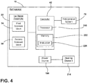
FIG. 4 is a block diagram of the refrigerator, according to one example. - For purposes of description herein the terms "upper," "lower," "right," "left," "rear," "front," "vertical," "horizontal," and derivatives thereof shall relate to the device as oriented in
FIG. 1 . However, it is to be understood that the device may assume various alternative orientations and step sequences, except where expressly specified to the contrary. It is also to be understood that the specific devices and processes illustrated in the attached drawings, and described in the following specification are simply exemplary embodiments of the inventive concepts defined in the appended claims. Hence, specific dimensions and other physical characteristics relating to the embodiments disclosed herein are not to be considered as limiting, unless the claims expressly state otherwise. - Referring to
FIGS. 1-4 ,reference numeral 10 generally designates a refrigerator including afreezer compartment 14. Amachine compartment 18 is positioned proximate to thefreezer compartment 14. Anicemaker assembly 22 is positioned within thefreezer compartment 14. Afill tube 30 extends from themachine compartment 18 into theicemaker assembly 22. Afirst solenoid valve 34 is coupled to thefill tube 30, and asecond solenoid valve 38 is coupled to thefill tube 30. The first andsecond solenoid valves machine compartment 18. Acontroller 42 is configured to open and close the first andsecond solenoid valves - Referring to
FIG. 1 , therefrigerator 10 has afresh food compartment 46 and afreezer compartment 14, however, other locations within thefreezer compartment 14 are contemplated as being suitable for theicemaker assembly 22 of the present concept. Therefrigerator 10 is illustrated as a French door bottom mount refrigerator. However, it is contemplated that therefrigerator 10 may be, for example, a bottom mount refrigerator, a top mount refrigerator, a side-by-side refrigerator, a 4-door French door refrigerator, and/or a 5-door French door refrigerator. Therefrigerator 10 includes awater dispenser 50 on adoor 54 of thefresh food compartment 46. As noted above, therefrigerator 10 further includes theicemaker assembly 22 positioned within thefreezer compartment 14. - Referring to
FIG. 2 , theicemaker assembly 22 is in theupper portion 26 of thefreezer compartment 14. Theicemaker assembly 22 includes ahousing 58 and anice tray 62 positioned in atop portion 66 of thehousing 58. As illustrated, theice tray 62 includes apower connection 70 to power ice cube formation and/or ice cube releasing functions of theice tray 62. Theicemaker assembly 22 further includes anice storage bin 74 positioned below theice tray 62. Theice storage bin 74 is configured to receive ice cubes released from theice tray 62 and store the ice cubes until the ice cubes are dispensed or otherwise retrieved by a user. - In various examples, the
machine compartment 18 is positioned proximate or directly adjacent to thefreezer compartment 14. As illustrated in the embodiment ofFIG. 2 , themachine compartment 18 is positioned behind thefreezer compartment 14. Themachine compartment 18, depicted inFIG. 2 , has a height that is substantially similar to a height of thefreezer compartment 14. However, it is contemplated that theupper portion 26 of thefreezer compartment 14 may extend a greater depth into therefrigerator 10, thereby limiting the height and/or depth of themachine compartment 18. Themachine compartment 18 houses arefrigeration system 78, including, for example, an evaporator, a condenser, and acompressor 82. - As illustrated in
FIG. 2 , thefill tube 30 includes afirst end 30A positioned within thehousing 58 of theicemaker assembly 22. Specifically, thefirst end 30A of thefill tube 30 is positioned proximate theice tray 62 within theicemaker assembly 22. Thefirst end 30A of thefill tube 30 includes anozzle 86 positioned above theice tray 62. Thenozzle 86 extends at a downward angle from atop surface 90 of thehousing 58 in a range of about 15° to about 60°. Thenozzle 86, as illustrated in the embodiment ofFIG. 2 , is coupled to thetop surface 90 of thehousing 58. It may be advantageous to couple thenozzle 86 to thehousing 58 or otherwise secure thenozzle 86 to prevent water flowing through thenozzle 86 from altering the position of thenozzle 86. It is also contemplated that thefill tube 30 may be coupled to thetop surface 90 of thehousing 58. - The
fill tube 30 extends from themachine compartment 18 into thefreezer compartment 14, and further extends into thehousing 58 of theicemaker assembly 22. Afirst portion 94 of thefill tube 30 is positioned within thehousing 58 of theicemaker assembly 22. Asecond portion 98 of thefill tube 30 is positioned outside of thehousing 58. In other words, thesecond portion 98 may be at least partially positioned within themachine compartment 18. Further, thesecond portion 98 may be at least partially positioned within thefreezer compartment 14. Additionally, thefill tube 30 includes asecond end 30B, which may be positioned within themachine compartment 18. Accordingly, thefill tube 30 has the first and second ends 30A, 30B with the first andsecond portions FIG. 2 , thefill tube 30 substantiallyvertical portions 106 positioned within the housing 28 and within thefreezer compartment 14 between arear surface 114 of thehousing 58 and adivider 118 separating thefreezer compartment 14 and themachine compartment 18. It is contemplated that thefill tube 30 may have onevertical portion 106 or more than onevertical portions 106. - Referring again to
FIG. 2 , in various examples, therear surface 114 of thehousing 58 includes a throughportion 122. The throughportion 122, as illustrated, may have a greater thickness than therear surface 114 of thehousing 58, however, it is contemplated that the throughportion 122 may be substantially flush with therear surface 114 to form a continuous surface. The throughportion 122 defines anaperture 126 for thefill tube 30 to extend through thehousing 58. Theaperture 126 may define a substantially similar cross-sectional shape and size as thefill tube 30, such that the throughportion 122 defining theaperture 126 abuts anouter surface 130 of thefill tube 30. Additionally or alternatively, the throughportion 122 may include a gasket or other similar structure to seal against theouter surface 130 of thefill tube 30, thereby preventing air in thehousing 58 from escaping to thefreezer compartment 14. The throughportion 122 is shown inFIG. 2 as being coupled to therear surface 114 of thehousing 58, however, it is contemplated that the throughportion 122 may be coupled to another surface of thehousing 58. Accordingly, it is contemplated that thefill tube 30 may extend into the housing in a different location based on the configuration of themachine compartment 18 and/or theicemaker assembly 22. Thefill tube 30 also traverses thedivider 118. Thedivider 118 may also define agap 124 for thefill tube 30 to traverse the divider 180. Thedivider 118 may form a seal about thefill tube 30 to prevent cold air from thefreezer compartment 14 escaping to themachine compartment 18. Thegap 124 may be substantially similar to the throughportion 122. Alternatively, there may be a combined throughportion 122. - The
fill tube 30 is illustrated as extending through therear surface 114 of thehousing 58. Additionally or alternatively, thefill tube 30 extends into thehousing 58 below theice tray 62. It is also contemplated that thefill tube 30 may extend into thehousing 58 above or substantially coplanar with theice tray 62. Thefirst portion 94 of thefill tube 30 positioned within thehousing 58 includes avertical portion 106. Further, thesecond portion 98 of thefill tube 30 positioned at least partially within thefreezer compartment 14 includes avertical portion 106. Thevertical portions 106 of the first andsecond portions fill tube 30 may include, for example, metal materials, metal alloy materials, and/or plastic materials. - Referring still to
FIG. 2 , thefill tube 30 is coupled to thefirst solenoid valve 34 and thesecond solenoid valve 38 within themachine compartment 18. Accordingly, the first andsecond solenoid valves second portion 98 of thefill tube 30, which extends into themachine compartment 18. The first andsecond solenoid valves second end 30B of thefill tube 30. Aninlet tube 146 is also coupled to thefirst solenoid valve 34. As illustrated, theinlet tube 146 extends from aback surface 150 of themachine compartment 18. In various examples, theback surface 150 of the machine compartment may coincide with a rearward surface 154 (FIG. 1 ) of therefrigerator 10. It is also contemplated that theinlet tube 146 may extend through theback surface 150 of themachine compartment 18 and/or therearward surface 154 of therefrigerator 10. It is further contemplated that theinlet tube 146 may extend out of another location of themachine compartment 18 and/orrefrigerator 10. Theinlet tube 146 includes aconnector 158 positioned at arear end portion 162 of theinlet tube 146. Theconnector 158 is configured to receive an external water supply line that provides water to theinlet tube 146 from a water source within a building (e.g., a house or a workplace). - The
fill tube 30 is further coupled to anoutlet tube 166. Theoutlet tube 166, as illustrated, is coupled to thesecond portion 98 of thefill tube 30 and thesecond solenoid valve 38. Theoutlet tube 166 is coupled to thefill tube 30 via a T-joint coupling 174, however, it is contemplated that other coupling members may be used without departing from the teachings herein. Theoutlet tube 166 is configured to allow water from thefill tube 30 to drain into adrain receptacle 178. Thedrain receptacle 178 is positioned within alower portion 182 of themachine compartment 18. As illustrated, thedrain receptacle 178 is positioned on thecompressor 82 and below thesecond solenoid valve 38. Thedrain receptacle 178 may be any size and/or shape container configured to receive water draining from thefill tube 30. Thedrain receptacle 178 may also be positioned in various locations based on the configuration of theicemaker assembly 22. - Referring to
FIGS. 2 and3 , thecontroller 42 is operably coupled to the first andsecond solenoid valves icemaker assembly 22. As discussed herein, the fill sequence generally supports filling theice tray 62 of theicemaker assembly 22 with water from a water supply source via interconnected tubes (e.g., thefill tube 30 and/or the inlet tube 146). As discussed herein, the drain sequence generally supports draining water from interconnected tubes between theicemaker assembly 22 and the machine compartment 18 (e.g., thefill tube 30 and/or a drain tube 190). The first andsecond solenoid valves controller 42 controls the first andsecond solenoid valves first solenoid valve 34 may be biased to the closed position. Thecontroller 42 is configured to open thefirst solenoid valve 34 to begin the fill sequence. Once in the opened position, thefirst solenoid valve 34 allows water to flow from theinlet tube 146 to thefill tube 30. The water travels through thefill tube 30, out thenozzle 86, and is inserted into theice tray 62. Accordingly, the fill sequence operates to provide water to theice tray 62. During the fill sequence, thesecond solenoid valve 38 remains in a closed position. It may be advantageous for thesecond solenoid valve 38 to be in the closed position during the fill sequence, such that water passing the T-joint coupling 174 continues through thefill tube 30 rather than diverting to thedrain tube 190. Additionally, the T-joint coupling 174 may also be configured to prevent water from entering theoutlet tube 166 during the fill sequence. - After the fill sequence is complete, the
controller 42 is configured to return thefirst solenoid valve 34 to the closed position and thereby prevent water from entering thefill tube 30. Thecontroller 42 is then configured to open thesecond solenoid valve 38. Thecontroller 42 may be configured to open thesecond solenoid valve 38 after a predetermined length of time has passed after the fill sequence is completed. In other words, thecontroller 42 may open the second solenoid valve 38 a predetermined amount of time after the fill sequence. It may be advantageous to time the opening of thesecond solenoid valve 38 so the water in thefill tube 30 is not drained prematurely thereby preventing or decreasing ice formation in theice tray 62. Once thesecond solenoid valve 38 is in an opened position, gravity operates to move water down thefill tube 30 in an opposite direction of the fill sequence, and through theoutlet tube 166. A drain sequence of theicemaker assembly 22 operates to drain remaining water in thefill tube 30 after a fill sequence. The water moves from thefill tube 30, through theoutlet tube 166, and is expelled through thesecond solenoid valve 38 into thedrain receptacle 178. In various examples, adrain tube 190 is coupled to thesecond solenoid valve 38 to direct the water from thesecond solenoid valve 38 to thedrain receptacle 178. However, the water may be expelled directly from thesecond solenoid valve 38 to thedrain receptacle 178 without thedrain tube 190. Additionally or alternatively, thefirst solenoid valve 34 is in the opened position and thesecond solenoid valve 38 is in the closed position during the fill sequence, and during the drain sequence, thesecond solenoid valve 38 is in the opened position and thefirst solenoid valve 34 is in the closed position. It is contemplated that other opening and closing sequences may be used without departing from the teachings herein. - Referring again to
FIGS. 2 and3 , the first andsecond solenoid valves electrical connection 194. Theelectrical connections 194 couple the first andsecond solenoid valves FIG. 4 ) within therefrigerator 10. Theelectrical connections 194 provide an electric current to the first andsecond solenoid valves second solenoid valves second solenoid valves second solenoid valves icemaker assembly 22 and/or therefrigerator 10. - In various examples, a
hydrophobic coating 202 is positioned on aninner surface 206 of thefill tube 30. In various examples, thehydrophobic coating 202 may be coupled to the first andsecond portions fill tube 30. Alternatively, the hydrophobic coating may be coupled to one of thefirst portion 94 or thesecond portion 98. It may be advantageous to include thehydrophobic coating 202 on the first andsecond portions fill tube 30 to prevent droplets of water from remaining on theinner surface 206 of thefill tube 30 after the fill and drain sequences. Similarly, it may be advantageous to include thehydrophobic coating 202 on thevertical portions 106 of thefill tube 30. The water droplets may freeze and interfere with subsequent fill and/or drain sequences of theicemaker assembly 22. Thehydrophobic coating 202 may further be advantageous when thefill tube 30 includes and/or is formed from plastic materials that may retain water droplets. - Referring still to
FIGS. 2 and3 , aheating element 214 is illustrated coupled to theouter surface 130 of thefill tube 30. Theheating element 214 may be a layer or coating positioned about theouter surface 130 of thefill tube 30. In various examples, theheating element 214 may be coupled to the first andsecond portions fill tube 30. Alternatively, the hydrophobic coating may be coupled to one of thefirst portion 94 or thesecond portion 98. It may be advantageous to include theheating element 214 on the first andsecond portions fill tube 30 or, more specifically, thevertical portions 106 of thefill tube 30 to melt any water that may freeze within thefill tube 30. Water that freezes within thefill tube 30 may prevent additional water from flowing through thefill tube 30 to theice tray 62 during the fill sequence. Accordingly, theheating element 214 may operate to melt ice within thefill tube 30. In such examples, it may be advantageous for thefill tube 30 to include and/or be formed from metals or metal alloys, such that thefill tube 30 is not damaged by theheating element 214. Theheating element 214 may be, for example, a thermally conductive material configured to conduct heat to thefill tube 30. - Referring to
FIGS. 3 and4 , theheating element 214 is coupled to thepower source 198. Thepower source 198 is configured to activate theheating element 214. In various examples, thecontroller 42 activates thepower source 198 which then conducts heat through theheating element 214. Thepower source 198 may be thesame power source 198 for therefrigerator 10 or may be aseparate power source 198. In various examples, thefill tube 30 may include theheating element 214, thehydrophobic coating 202, and/or a combination thereof. It is also contemplated that thefill tube 30 does not include thehydrophobic coating 202 or theheating element 214. Thecontroller 42 may also be configured to activate theheating element 214 and/or thepower source 198 before or after one of a fill sequence and a drain sequence. Additionally or alternatively, thecontroller 42 may be configured to activate theheating element 214 and/orpower source 198 after a predetermined amount of time after the completion of one of the fill sequence and/or the drain sequence. Additionally or alternatively still, thecontroller 42 may be configured to activate theheating element 214 and/orpower source 198 during one of the fill sequence and drain sequence. - Referring to
FIG. 4 , thecontroller 42 includes aprocessor 218, other control circuitry, and amemory 222. Stored in thememory 222 and executable by theprocessor 218 areinstructions 226. Thememory 222 may storevarious instructions 226 relating to various functions. For example, theinstructions 226 include at least oneinstruction 226 relating to the functions of therefrigeration system 78. Theinstructions 226 may also include at least oneinstruction 226 for starting and/or stopping the fill sequence and the drain sequence of theicemaker assembly 22. Thecontroller 42 may also be operably coupled to the first andsecond solenoid valves controller 42 is configured to open and close the first andsecond solenoid valves controller 42 may be configured to open thesecond solenoid valve 38 after a predetermined length of time from completion of the fill sequence. In such examples, thecontroller 42 is configured to open thesecond solenoid valve 38 to drain water from thefill tube 30 via theoutlet tube 166 during the drain sequence. - Use of the present concept may provide for a variety of advantages. For example, the
fill tube 30 may include thevertical portions 106 positioned within at least one of the housing 28 and thefreezer compartment 14. In such examples, water may remain in thevertical portions 106 or other locations within thefill tube 30. Theicemaker assembly 22 disclosed herein may drain water from thefill tube 30 and reduce the amount of water that may remain, and freeze, within thefill tube 30. Additionally, thefill tube 30 may include thehydrophobic coating 202 on theinner surface 206 of thefill tube 30. Thehydrophobic coating 202 may reduce water droplets that remain on theinner surface 206 of thefill tube 30. In a third example, theheating element 214 may be coupled to thefill tube 30. Theheating element 214 may conduct heat to thefill tube 30 and melt ice that may remain within thefill tube 30. Further, use of the presently disclosedicemaker assembly 22, including the first andsecond solenoid valves hydrophobic coating 202, may reduce the use of theheating element 214, which may reduce energy consumption. Additional benefits or advantages of using this device may also be realized and/or achieved. - According to at least one aspect, a refrigerator includes a freezer compartment and a machine compartment positioned proximate the freezer compartment. An icemaker assembly is positioned within the freezer compartment. A fill tube extends from the machine compartment to the icemaker assembly. A first solenoid valve is coupled to the fill tube. A second solenoid valve is coupled to the fill tube, wherein the first and second solenoid valves are positioned within the machine compartment. A controller is configured to independently open and close the first and second solenoid valves.
- According to another aspect, a drain receptacle is positioned within the machine compartment and configured to receive water from the second solenoid valve.
- According to another aspect, a substantially vertical portion of the fill tube is positioned within the freezer compartment.
- According to still another aspect, an outlet tube is coupled to the fill tube via a T-joint coupling.
- According to another aspect, the first solenoid valve is in an opened position during a fill sequence and the second solenoid valve is in a closed position during the fill sequence.
- According to another aspect, the second solenoid valve is in an opened position during a drain sequence and the first solenoid valve is in a closed position during the drain sequence.
- According to yet another aspect, the controller opens the second solenoid valve a predetermined amount of time after a fill sequence.
- According to at least one aspect, an icemaker assembly for a refrigerator includes a housing and an ice tray positioned within the housing. A fill tube includes a first portion positioned within the housing and a second portion positioned outside of the housing. An outlet tube is coupled to the second portion of the fill tube. A first solenoid valve is coupled to the fill tube, and a second solenoid valve is coupled to the fill tube, wherein the first and second solenoid valves are operable between opened and closed positions.
- According to another aspect, the first and second solenoid valves are coupled to the second portion of the fill tube.
- According to still another aspect, a hydrophobic coating is positioned on an inner surface of the fill tube.
- According to another aspect, an inlet tube is coupled to the first solenoid valve.
- According to yet another aspect, the first solenoid valve is in the closed position during a drain sequence.
- According to another aspect, a controller configured to control the first and second solenoid valves between the opened and closed positions.
- According to another aspect, the controller is configured to open the second solenoid valve a predetermined amount of time after completion of a fill sequence.
- According to another aspect, the outlet tube is coupled to the fill tube via a T-joint coupling, and further wherein the T-joint coupling is configured to prevent water from entering the outlet tube during a fill sequence.
- According to at least one aspect, an icemaker assembly for a refrigerator includes a housing and an ice tray positioned within the housing. A fill tube has first and second ends with first and second portions disposed therebetween. The first end is positioned proximate to the ice tray. The first portion of the fill tube is positioned within the housing and the second portion of the fill tube is positioned outside the housing. A solenoid valve is coupled to the second end of the fill tube. An outlet tube is coupled to the fill tube. A controller is operably coupled to the solenoid valve for controlling the same.
- According to another aspect, the fill tube includes a metal material.
- According to yet another aspect, a heating element is coupled to an outer surface of the fill tube.
- According to still another aspect, a power source is coupled to the heating element, wherein the power source is configured to activate the heating element before or after one of a fill sequence and a drain sequence.
- According to another aspect, the controller is configured to open the solenoid valve to drain water from the fill tube via the outlet tube during a drain sequence.
Claims (15)
- An icemaker assembly (22) for a refrigerator (10), comprising:a housing (58);an ice tray (62) positioned within the housing (58);a fill tube (30) having a first portion (94) positioned within the housing (58) and a second portion (98) positioned outside of the housing (58);a first solenoid valve (34) coupled to the second portion (98) of the fill tube (30);an outlet tube (166) coupled to the second portion (98) of the fill tube (30); anda second solenoid valve (38) coupled to the outlet tube (166), wherein the first and second solenoid valves (34, 38) are operable between opened and closed positions.
- The icemaker assembly (22) of claim 1, further comprising:
a controller (42) configured to control the first and second solenoid valves (34, 38) between the opened and closed positions. - The icemaker assembly (22) of claim 2, wherein the controller (42) is configured to open the second solenoid valve (38) to drain water from the fill tube (30) via the outlet tube (166) during a drain sequence.
- The icemaker assembly (22) of claims 3, wherein the controller (42) is configured to open the second solenoid valve (38) a predetermined amount of time after completion of a fill sequence.
- The icemaker assembly (22) of any of claims 1-4, further comprising:
an inlet tube (146) coupled to the first solenoid valve (34). - The icemaker assembly (22) of any of claims 1-5, wherein the first solenoid valve (34) is in the closed position during a drain sequence.
- The icemaker assembly (22) of any of claims 1-6, wherein the outlet tube (166) is coupled to the fill tube (30) via a T-joint coupling (174).
- The icemaker assembly (22) of claim 7, wherein the T-joint coupling (174) is configured to prevent water from entering the outlet tube (166) during a fill sequence.
- The icemaker assembly (22) of any of claims 1-8, wherein the second solenoid valve (38) is in the opened position during a drain sequence.
- The icemaker assembly (22) of any of claims 1-9, wherein the first solenoid valve (34) is in the opened position during a fill sequence and the second solenoid valve (38) is in the closed position during the fill sequence.
- The icemaker assembly (22) of any of claims 1-10, further comprising:
a drain receptacle (178) configured to receive water from the second solenoid valve (38). - The icemaker assembly (22) of any of claims 1-11, further comprising:
a heating element (214) coupled to an outer surface (130) of the fill tube (30). - The icemaker assembly (22) of claim 12, further comprising:
a power source (198) coupled to the heating element (214), wherein the power source (198) is configured to activate the heating element (214) before or after one of a fill sequence and a drain sequence. - The icemaker assembly (22) of any of claims 1-13, further comprising:
a hydrophobic coating (202) positioned on an inner surface (206) of the fill tube (30). - A refrigerator appliance comprising the icemaker assembly (22) of any one of the precedeing claims.
Applications Claiming Priority (1)
| Application Number | Priority Date | Filing Date | Title |
|---|---|---|---|
| US16/399,352 US11226146B2 (en) | 2019-04-30 | 2019-04-30 | Icemaker assembly |
Publications (2)
| Publication Number | Publication Date |
|---|---|
| EP3734200A1 true EP3734200A1 (en) | 2020-11-04 |
| EP3734200B1 EP3734200B1 (en) | 2023-01-11 |
Family
ID=70008401
Family Applications (1)
| Application Number | Title | Priority Date | Filing Date |
|---|---|---|---|
| EP20165721.0A Active EP3734200B1 (en) | 2019-04-30 | 2020-03-25 | Icemaker assembly |
Country Status (3)
| Country | Link |
|---|---|
| US (3) | US11226146B2 (en) |
| EP (1) | EP3734200B1 (en) |
| CN (1) | CN111854267B (en) |
Families Citing this family (1)
| Publication number | Priority date | Publication date | Assignee | Title |
|---|---|---|---|---|
| US20230304717A1 (en) * | 2022-03-22 | 2023-09-28 | Whirlpool Corporation | Water fill tube with thermally conductive filled polymer |
Citations (6)
| Publication number | Priority date | Publication date | Assignee | Title |
|---|---|---|---|---|
| US1395411A (en) * | 1920-07-31 | 1921-11-01 | Hessel Philip | Ice-machine |
| US3866434A (en) * | 1973-11-15 | 1975-02-18 | Gen Motors Corp | Meniscus control insert for automatic ice maker water fill tube |
| GB2275328A (en) * | 1993-02-19 | 1994-08-24 | Mitsubishi Electric Corp | Apparatus for automatically making ice |
| US6041607A (en) * | 1998-10-31 | 2000-03-28 | Daewoo Electronics Co., Ltd. | Refrigerator having a liquid supplying device for an ice tray |
| US20060196212A1 (en) * | 2005-03-07 | 2006-09-07 | Maytag Corp. | Water delivery system with water flow sensor for a refrigerator |
| KR100998198B1 (en) * | 2010-02-18 | 2010-12-03 | 주식회사 태성 | Circulating Transparent Ice Ice Maker |
Family Cites Families (26)
| Publication number | Priority date | Publication date | Assignee | Title |
|---|---|---|---|---|
| US2717506A (en) | 1952-12-10 | 1955-09-13 | Servel Inc | Ice maker |
| US2963885A (en) * | 1958-10-31 | 1960-12-13 | Gen Electric | Automatic ice maker |
| US3411554A (en) | 1965-09-27 | 1968-11-19 | Kelvinator Inc | Refrigerator tray filling device |
| US4274263A (en) * | 1978-04-24 | 1981-06-23 | Goushaw David W | Continuously refrigerated, automatically ejected block ice machine |
| KR100197906B1 (en) * | 1996-10-21 | 1999-06-15 | 전주범 | Automatic ice maker water dispenser in refrigerator |
| KR100572878B1 (en) * | 1999-06-08 | 2006-04-24 | 주식회사 엘지이아이 | Water Purification Flow Control Method of Filter-Type Refrigerator |
| US6895788B2 (en) * | 1999-08-30 | 2005-05-24 | Mcsm, Llc | Appliance safety valve assembly |
| KR100377771B1 (en) * | 2001-02-15 | 2003-03-29 | 주식회사 엘지이아이 | Operating structure of a pipe heater for auto ice maker in refrigerator |
| JP2002243330A (en) * | 2001-02-20 | 2002-08-28 | Fujitsu General Ltd | Refrigerator with automatic ice making device and control method thereof |
| KR100390789B1 (en) * | 2001-05-08 | 2003-07-12 | 주식회사 엘지이아이 | Apparatus for preventing ice formation of a water pipe in a refrigerator and method thereof |
| US6763845B2 (en) * | 2002-09-09 | 2004-07-20 | Javier J. Hoggard | Water freeze prevention device |
| KR100748521B1 (en) * | 2005-03-17 | 2007-08-13 | 엘지전자 주식회사 | Refrigerator with water filter |
| FR2885290B1 (en) * | 2005-05-04 | 2007-06-01 | Seb Sa | COFFEE MACHINE WITH SEVERAL INFUSION HEADS |
| KR20070044247A (en) * | 2005-10-24 | 2007-04-27 | 삼성전자주식회사 | Refrigerator |
| CN201199117Y (en) * | 2008-04-09 | 2009-02-25 | 河南新飞电器有限公司 | Refrigerator with water supply system |
| BRPI0803585B1 (en) * | 2008-10-01 | 2019-05-07 | Whirlpool S.A. | DEVICE AND PROCESS FOR FILLING A CONTAINER WITH ICE-MAKING FORMS |
| KR101548263B1 (en) * | 2008-10-02 | 2015-08-28 | 삼성전자 주식회사 | Refrigerator |
| CN102116565B (en) * | 2011-01-21 | 2013-01-09 | 合肥美的荣事达电冰箱有限公司 | Water supply device for refrigerator and refrigerator with same |
| US8919145B2 (en) | 2011-06-22 | 2014-12-30 | Whirlpool Corporation | Vertical ice maker with microchannel evaporator |
| KR101995426B1 (en) * | 2012-09-26 | 2019-07-02 | 엘지전자 주식회사 | Refrigerator and Controlling Method for the same |
| CN204085038U (en) * | 2014-07-22 | 2015-01-07 | 合肥晶弘电器有限公司 | A kind of refrigerator water system and refrigerator |
| CN104089454A (en) * | 2014-07-22 | 2014-10-08 | 合肥晶弘电器有限公司 | Refrigerator water supply system and refrigerator |
| CN107532837A (en) | 2015-05-06 | 2018-01-02 | 真实制造有限公司 | With to maintain clean condenser reverse condenser fan motor ice machine |
| CN107830668B (en) * | 2017-10-31 | 2019-08-27 | 海信容声(广东)冰箱有限公司 | A water inlet component of a refrigerator ice maker and a refrigerator |
| US10641535B2 (en) * | 2018-03-19 | 2020-05-05 | Emerson Climate Technologies, Inc. | Ice maker and method of making and harvesting ice |
| CN209743833U (en) * | 2019-03-27 | 2019-12-06 | 陕西帝通实业有限公司 | Reduce feed pipe of flow resistance |
-
2019
- 2019-04-30 US US16/399,352 patent/US11226146B2/en active Active
-
2020
- 2020-03-25 EP EP20165721.0A patent/EP3734200B1/en active Active
- 2020-04-27 CN CN202010346462.4A patent/CN111854267B/en not_active Expired - Fee Related
-
2021
- 2021-09-22 US US17/481,546 patent/US11953249B2/en active Active
-
2024
- 2024-03-19 US US18/609,016 patent/US12618596B2/en active Active
Patent Citations (6)
| Publication number | Priority date | Publication date | Assignee | Title |
|---|---|---|---|---|
| US1395411A (en) * | 1920-07-31 | 1921-11-01 | Hessel Philip | Ice-machine |
| US3866434A (en) * | 1973-11-15 | 1975-02-18 | Gen Motors Corp | Meniscus control insert for automatic ice maker water fill tube |
| GB2275328A (en) * | 1993-02-19 | 1994-08-24 | Mitsubishi Electric Corp | Apparatus for automatically making ice |
| US6041607A (en) * | 1998-10-31 | 2000-03-28 | Daewoo Electronics Co., Ltd. | Refrigerator having a liquid supplying device for an ice tray |
| US20060196212A1 (en) * | 2005-03-07 | 2006-09-07 | Maytag Corp. | Water delivery system with water flow sensor for a refrigerator |
| KR100998198B1 (en) * | 2010-02-18 | 2010-12-03 | 주식회사 태성 | Circulating Transparent Ice Ice Maker |
Also Published As
| Publication number | Publication date |
|---|---|
| EP3734200B1 (en) | 2023-01-11 |
| US20220003476A1 (en) | 2022-01-06 |
| US20240219093A1 (en) | 2024-07-04 |
| US11226146B2 (en) | 2022-01-18 |
| CN111854267B (en) | 2024-10-11 |
| US11953249B2 (en) | 2024-04-09 |
| US12618596B2 (en) | 2026-05-05 |
| US20200348065A1 (en) | 2020-11-05 |
| CN111854267A (en) | 2020-10-30 |
Similar Documents
| Publication | Publication Date | Title |
|---|---|---|
| EP3584525B1 (en) | Refrigerator | |
| EP2474798B1 (en) | Refrigerator with an ice-making device | |
| US10982892B2 (en) | Refrigerator having ice maker and refrigeration circuit therefor | |
| EP3899385B1 (en) | Ice machine | |
| US20100218518A1 (en) | Ice maker control system and method | |
| US20110302951A1 (en) | Refrigerator, ice maker for a refrigerator, and method for making ice | |
| EP3517854B1 (en) | Refrigerator and control method of a refrigerator | |
| WO2020233541A1 (en) | Refrigeration appliance having ice storage box | |
| US9091473B2 (en) | Float-type ice making assembly and related refrigeration appliance | |
| US12618596B2 (en) | Icemaker assembly | |
| CN115335651B (en) | Refrigeration appliance with ice making and dispensing system | |
| US8640488B2 (en) | Ice bin assembly | |
| KR101519877B1 (en) | Ice maker and refrigerator having the same | |
| KR100845151B1 (en) | Ice maker | |
| US10480842B2 (en) | Compact ice making system for slimline ice compartment | |
| EP2097695B1 (en) | Refrigerator | |
| KR20160148856A (en) | Refrigerator and ice making method thereof | |
| KR100565609B1 (en) | Refrigerator | |
| CN100464145C (en) | Water supply pipe of dispenser for refrigerator | |
| CN114719512B (en) | refrigerator | |
| KR100737455B1 (en) | Refrigerator and its manufacturing method |
Legal Events
| Date | Code | Title | Description |
|---|---|---|---|
| PUAI | Public reference made under article 153(3) epc to a published international application that has entered the european phase |
Free format text: ORIGINAL CODE: 0009012 |
|
| STAA | Information on the status of an ep patent application or granted ep patent |
Free format text: STATUS: THE APPLICATION HAS BEEN PUBLISHED |
|
| AK | Designated contracting states |
Kind code of ref document: A1 Designated state(s): AL AT BE BG CH CY CZ DE DK EE ES FI FR GB GR HR HU IE IS IT LI LT LU LV MC MK MT NL NO PL PT RO RS SE SI SK SM TR |
|
| AX | Request for extension of the european patent |
Extension state: BA ME |
|
| STAA | Information on the status of an ep patent application or granted ep patent |
Free format text: STATUS: REQUEST FOR EXAMINATION WAS MADE |
|
| 17P | Request for examination filed |
Effective date: 20210322 |
|
| RBV | Designated contracting states (corrected) |
Designated state(s): AL AT BE BG CH CY CZ DE DK EE ES FI FR GB GR HR HU IE IS IT LI LT LU LV MC MK MT NL NO PL PT RO RS SE SI SK SM TR |
|
| RIC1 | Information provided on ipc code assigned before grant |
Ipc: F25C 1/25 20180101AFI20220923BHEP |
|
| GRAP | Despatch of communication of intention to grant a patent |
Free format text: ORIGINAL CODE: EPIDOSNIGR1 |
|
| STAA | Information on the status of an ep patent application or granted ep patent |
Free format text: STATUS: GRANT OF PATENT IS INTENDED |
|
| INTG | Intention to grant announced |
Effective date: 20221107 |
|
| GRAS | Grant fee paid |
Free format text: ORIGINAL CODE: EPIDOSNIGR3 |
|
| GRAA | (expected) grant |
Free format text: ORIGINAL CODE: 0009210 |
|
| STAA | Information on the status of an ep patent application or granted ep patent |
Free format text: STATUS: THE PATENT HAS BEEN GRANTED |
|
| AK | Designated contracting states |
Kind code of ref document: B1 Designated state(s): AL AT BE BG CH CY CZ DE DK EE ES FI FR GB GR HR HU IE IS IT LI LT LU LV MC MK MT NL NO PL PT RO RS SE SI SK SM TR |
|
| REG | Reference to a national code |
Ref country code: GB Ref legal event code: FG4D |
|
| REG | Reference to a national code |
Ref country code: CH Ref legal event code: EP |
|
| REG | Reference to a national code |
Ref country code: DE Ref legal event code: R096 Ref document number: 602020007450 Country of ref document: DE |
|
| REG | Reference to a national code |
Ref country code: IE Ref legal event code: FG4D |
|
| REG | Reference to a national code |
Ref country code: AT Ref legal event code: REF Ref document number: 1543666 Country of ref document: AT Kind code of ref document: T Effective date: 20230215 |
|
| REG | Reference to a national code |
Ref country code: LT Ref legal event code: MG9D |
|
| REG | Reference to a national code |
Ref country code: NL Ref legal event code: MP Effective date: 20230111 |
|
| REG | Reference to a national code |
Ref country code: AT Ref legal event code: MK05 Ref document number: 1543666 Country of ref document: AT Kind code of ref document: T Effective date: 20230111 |
|
| P01 | Opt-out of the competence of the unified patent court (upc) registered |
Effective date: 20230523 |
|
| PG25 | Lapsed in a contracting state [announced via postgrant information from national office to epo] |
Ref country code: NL Free format text: LAPSE BECAUSE OF FAILURE TO SUBMIT A TRANSLATION OF THE DESCRIPTION OR TO PAY THE FEE WITHIN THE PRESCRIBED TIME-LIMIT Effective date: 20230111 |
|
| PG25 | Lapsed in a contracting state [announced via postgrant information from national office to epo] |
Ref country code: RS Free format text: LAPSE BECAUSE OF FAILURE TO SUBMIT A TRANSLATION OF THE DESCRIPTION OR TO PAY THE FEE WITHIN THE PRESCRIBED TIME-LIMIT Effective date: 20230111 Ref country code: PT Free format text: LAPSE BECAUSE OF FAILURE TO SUBMIT A TRANSLATION OF THE DESCRIPTION OR TO PAY THE FEE WITHIN THE PRESCRIBED TIME-LIMIT Effective date: 20230511 Ref country code: NO Free format text: LAPSE BECAUSE OF FAILURE TO SUBMIT A TRANSLATION OF THE DESCRIPTION OR TO PAY THE FEE WITHIN THE PRESCRIBED TIME-LIMIT Effective date: 20230411 Ref country code: LV Free format text: LAPSE BECAUSE OF FAILURE TO SUBMIT A TRANSLATION OF THE DESCRIPTION OR TO PAY THE FEE WITHIN THE PRESCRIBED TIME-LIMIT Effective date: 20230111 Ref country code: LT Free format text: LAPSE BECAUSE OF FAILURE TO SUBMIT A TRANSLATION OF THE DESCRIPTION OR TO PAY THE FEE WITHIN THE PRESCRIBED TIME-LIMIT Effective date: 20230111 Ref country code: HR Free format text: LAPSE BECAUSE OF FAILURE TO SUBMIT A TRANSLATION OF THE DESCRIPTION OR TO PAY THE FEE WITHIN THE PRESCRIBED TIME-LIMIT Effective date: 20230111 Ref country code: ES Free format text: LAPSE BECAUSE OF FAILURE TO SUBMIT A TRANSLATION OF THE DESCRIPTION OR TO PAY THE FEE WITHIN THE PRESCRIBED TIME-LIMIT Effective date: 20230111 Ref country code: AT Free format text: LAPSE BECAUSE OF FAILURE TO SUBMIT A TRANSLATION OF THE DESCRIPTION OR TO PAY THE FEE WITHIN THE PRESCRIBED TIME-LIMIT Effective date: 20230111 |
|
| PG25 | Lapsed in a contracting state [announced via postgrant information from national office to epo] |
Ref country code: SE Free format text: LAPSE BECAUSE OF FAILURE TO SUBMIT A TRANSLATION OF THE DESCRIPTION OR TO PAY THE FEE WITHIN THE PRESCRIBED TIME-LIMIT Effective date: 20230111 Ref country code: PL Free format text: LAPSE BECAUSE OF FAILURE TO SUBMIT A TRANSLATION OF THE DESCRIPTION OR TO PAY THE FEE WITHIN THE PRESCRIBED TIME-LIMIT Effective date: 20230111 Ref country code: IS Free format text: LAPSE BECAUSE OF FAILURE TO SUBMIT A TRANSLATION OF THE DESCRIPTION OR TO PAY THE FEE WITHIN THE PRESCRIBED TIME-LIMIT Effective date: 20230511 Ref country code: GR Free format text: LAPSE BECAUSE OF FAILURE TO SUBMIT A TRANSLATION OF THE DESCRIPTION OR TO PAY THE FEE WITHIN THE PRESCRIBED TIME-LIMIT Effective date: 20230412 Ref country code: FI Free format text: LAPSE BECAUSE OF FAILURE TO SUBMIT A TRANSLATION OF THE DESCRIPTION OR TO PAY THE FEE WITHIN THE PRESCRIBED TIME-LIMIT Effective date: 20230111 |
|
| REG | Reference to a national code |
Ref country code: DE Ref legal event code: R097 Ref document number: 602020007450 Country of ref document: DE |
|
| PG25 | Lapsed in a contracting state [announced via postgrant information from national office to epo] |
Ref country code: SM Free format text: LAPSE BECAUSE OF FAILURE TO SUBMIT A TRANSLATION OF THE DESCRIPTION OR TO PAY THE FEE WITHIN THE PRESCRIBED TIME-LIMIT Effective date: 20230111 Ref country code: RO Free format text: LAPSE BECAUSE OF FAILURE TO SUBMIT A TRANSLATION OF THE DESCRIPTION OR TO PAY THE FEE WITHIN THE PRESCRIBED TIME-LIMIT Effective date: 20230111 Ref country code: MC Free format text: LAPSE BECAUSE OF FAILURE TO SUBMIT A TRANSLATION OF THE DESCRIPTION OR TO PAY THE FEE WITHIN THE PRESCRIBED TIME-LIMIT Effective date: 20230111 Ref country code: EE Free format text: LAPSE BECAUSE OF FAILURE TO SUBMIT A TRANSLATION OF THE DESCRIPTION OR TO PAY THE FEE WITHIN THE PRESCRIBED TIME-LIMIT Effective date: 20230111 Ref country code: DK Free format text: LAPSE BECAUSE OF FAILURE TO SUBMIT A TRANSLATION OF THE DESCRIPTION OR TO PAY THE FEE WITHIN THE PRESCRIBED TIME-LIMIT Effective date: 20230111 Ref country code: CZ Free format text: LAPSE BECAUSE OF FAILURE TO SUBMIT A TRANSLATION OF THE DESCRIPTION OR TO PAY THE FEE WITHIN THE PRESCRIBED TIME-LIMIT Effective date: 20230111 |
|
| REG | Reference to a national code |
Ref country code: CH Ref legal event code: PL |
|
| PLBE | No opposition filed within time limit |
Free format text: ORIGINAL CODE: 0009261 |
|
| STAA | Information on the status of an ep patent application or granted ep patent |
Free format text: STATUS: NO OPPOSITION FILED WITHIN TIME LIMIT |
|
| PG25 | Lapsed in a contracting state [announced via postgrant information from national office to epo] |
Ref country code: SK Free format text: LAPSE BECAUSE OF FAILURE TO SUBMIT A TRANSLATION OF THE DESCRIPTION OR TO PAY THE FEE WITHIN THE PRESCRIBED TIME-LIMIT Effective date: 20230111 |
|
| REG | Reference to a national code |
Ref country code: BE Ref legal event code: MM Effective date: 20230331 |
|
| 26N | No opposition filed |
Effective date: 20231012 |
|
| PG25 | Lapsed in a contracting state [announced via postgrant information from national office to epo] |
Ref country code: LU Free format text: LAPSE BECAUSE OF NON-PAYMENT OF DUE FEES Effective date: 20230325 |
|
| REG | Reference to a national code |
Ref country code: IE Ref legal event code: MM4A |
|
| PG25 | Lapsed in a contracting state [announced via postgrant information from national office to epo] |
Ref country code: SI Free format text: LAPSE BECAUSE OF FAILURE TO SUBMIT A TRANSLATION OF THE DESCRIPTION OR TO PAY THE FEE WITHIN THE PRESCRIBED TIME-LIMIT Effective date: 20230111 Ref country code: LI Free format text: LAPSE BECAUSE OF NON-PAYMENT OF DUE FEES Effective date: 20230331 Ref country code: IE Free format text: LAPSE BECAUSE OF NON-PAYMENT OF DUE FEES Effective date: 20230325 Ref country code: CH Free format text: LAPSE BECAUSE OF NON-PAYMENT OF DUE FEES Effective date: 20230331 |
|
| PG25 | Lapsed in a contracting state [announced via postgrant information from national office to epo] |
Ref country code: BE Free format text: LAPSE BECAUSE OF NON-PAYMENT OF DUE FEES Effective date: 20230331 |
|
| PGFP | Annual fee paid to national office [announced via postgrant information from national office to epo] |
Ref country code: DE Payment date: 20240328 Year of fee payment: 5 Ref country code: GB Payment date: 20240319 Year of fee payment: 5 |
|
| PGFP | Annual fee paid to national office [announced via postgrant information from national office to epo] |
Ref country code: IT Payment date: 20240321 Year of fee payment: 5 Ref country code: FR Payment date: 20240326 Year of fee payment: 5 |
|
| PG25 | Lapsed in a contracting state [announced via postgrant information from national office to epo] |
Ref country code: BG Free format text: LAPSE BECAUSE OF FAILURE TO SUBMIT A TRANSLATION OF THE DESCRIPTION OR TO PAY THE FEE WITHIN THE PRESCRIBED TIME-LIMIT Effective date: 20230111 |
|
| PG25 | Lapsed in a contracting state [announced via postgrant information from national office to epo] |
Ref country code: BG Free format text: LAPSE BECAUSE OF FAILURE TO SUBMIT A TRANSLATION OF THE DESCRIPTION OR TO PAY THE FEE WITHIN THE PRESCRIBED TIME-LIMIT Effective date: 20230111 |
|
| PG25 | Lapsed in a contracting state [announced via postgrant information from national office to epo] |
Ref country code: CY Free format text: LAPSE BECAUSE OF FAILURE TO SUBMIT A TRANSLATION OF THE DESCRIPTION OR TO PAY THE FEE WITHIN THE PRESCRIBED TIME-LIMIT; INVALID AB INITIO Effective date: 20200325 |
|
| PG25 | Lapsed in a contracting state [announced via postgrant information from national office to epo] |
Ref country code: HU Free format text: LAPSE BECAUSE OF FAILURE TO SUBMIT A TRANSLATION OF THE DESCRIPTION OR TO PAY THE FEE WITHIN THE PRESCRIBED TIME-LIMIT; INVALID AB INITIO Effective date: 20200325 |
|
| REG | Reference to a national code |
Ref country code: DE Ref legal event code: R119 Ref document number: 602020007450 Country of ref document: DE |
|
| GBPC | Gb: european patent ceased through non-payment of renewal fee |
Effective date: 20250325 |
|
| PG25 | Lapsed in a contracting state [announced via postgrant information from national office to epo] |
Ref country code: TR Free format text: LAPSE BECAUSE OF FAILURE TO SUBMIT A TRANSLATION OF THE DESCRIPTION OR TO PAY THE FEE WITHIN THE PRESCRIBED TIME-LIMIT Effective date: 20230111 |
|
| PG25 | Lapsed in a contracting state [announced via postgrant information from national office to epo] |
Ref country code: DE Free format text: LAPSE BECAUSE OF NON-PAYMENT OF DUE FEES Effective date: 20251001 |
|
| PG25 | Lapsed in a contracting state [announced via postgrant information from national office to epo] |
Ref country code: GB Free format text: LAPSE BECAUSE OF NON-PAYMENT OF DUE FEES Effective date: 20250325 |
|
| PG25 | Lapsed in a contracting state [announced via postgrant information from national office to epo] |
Ref country code: FR Free format text: LAPSE BECAUSE OF NON-PAYMENT OF DUE FEES Effective date: 20250331 Ref country code: IT Free format text: LAPSE BECAUSE OF NON-PAYMENT OF DUE FEES Effective date: 20250325 |